In this tutorial we will learn how servo motors work and how to control servo motors with Arduino. Servo motors are very popular and widely used in many Arduino projects because they are easy to use and provide great position control.
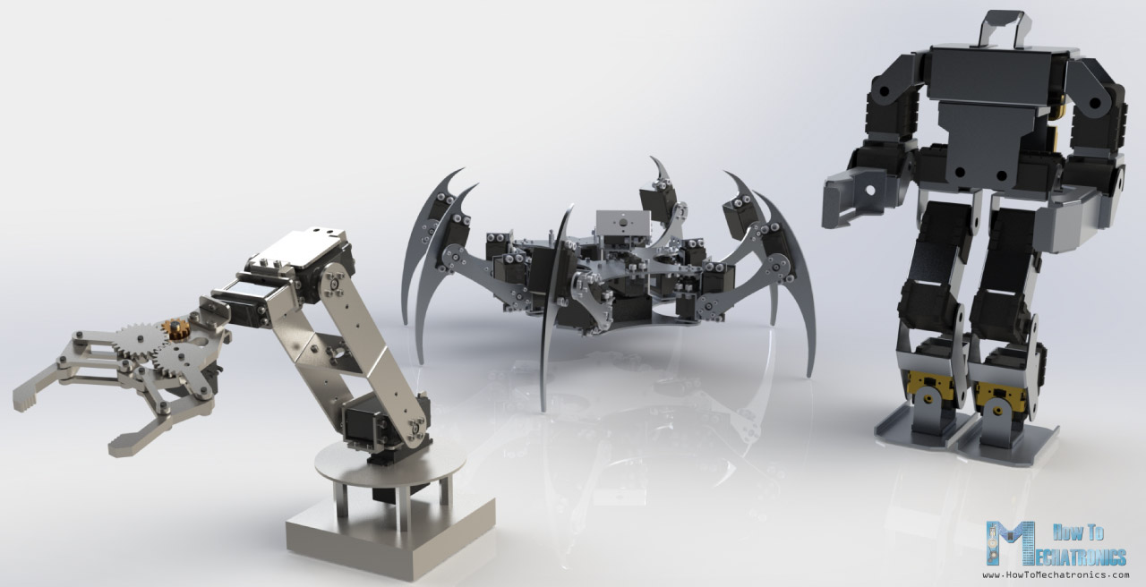
Servos are great choice for robotics projects, automation, RC models and so on. I have already used them in many of my Arduino projects and you can check out some of them here:
- DIY Arduino Robot Arm with Smartphone Control
- Arduino Ant Hexapod Robot
- DIY Arduino based RC Hovercraft
- SCARA Robot | How To Build Your Own Arduino Based Robot
- DIY Mars Perseverance Rover Replica – Arduino based Project
You can watch the following video or read the written tutorial below. It includes several examples how to use a servo motor with Arduino, wiring diagram and codes. In additional, it has a guide how to control multiple servo motors with Arduino using the PCA9685 PWM driver.
What is Servo Motor?
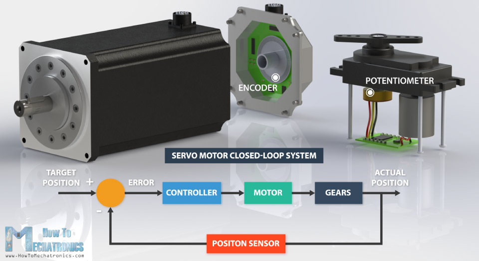
A servo motor is a closed-loop system that uses position feedback to control its motion and final position. There are many types of servo motors and their main feature is the ability to precisely control the position of their shaft.
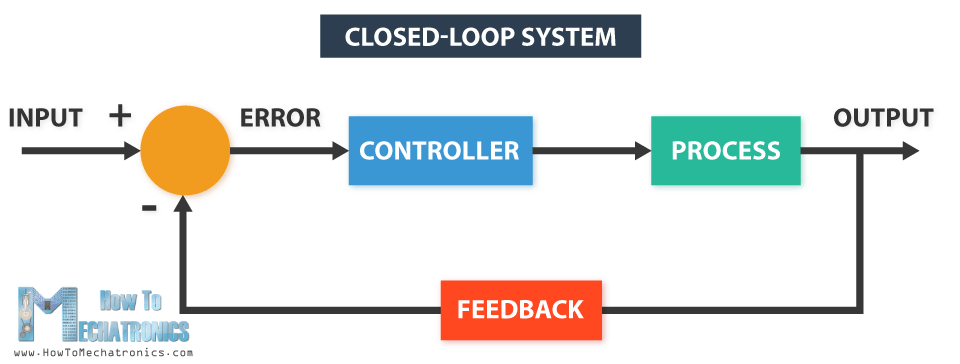
In industrial type servo motors the position feedback sensor is usually a high precision encoder, while in the smaller RC or hobby servos the position sensor is usually a simple potentiometer. The actual position captured by these devices is fed back to the error detector where it is compared to the target position. Then according to the error the controller corrects the actual position of the motor to match with the target position.
In this tutorial we will take a detailed look at the hobby servo motors. We will explain how these servos work and how to control them using Arduino.
Hobby servos are small in size actuators used for controlling RC toys cars, boats, airplanes etc. They are also used by engineering students for prototyping in robotics, creating robotic arms, biologically inspired robots, humanoid robots and so on.
How Servo Motors Work?
There are four main components inside of a hobby servo, a DC motor, a gearbox, a potentiometer and a control circuit. The DC motor is high speed and low torque but the gearbox reduces the speed to around 60 RPM and at the same time increases the torque.
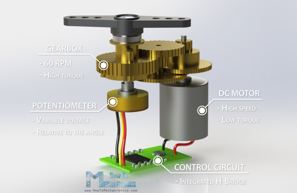
The potentiometer is attached on the final gear or the output shaft, so as the motor rotates the potentiometer rotates as well, thus producing a voltage that is related to the absolute angle of the output shaft. In the control circuit, this potentiometer voltage is compared to the voltage coming from the signal line. If needed, the controller activates an integrated H-Bridge which enables the motor to rotate in either direction until the two signals reach a difference of zero.
A servo motor is controlled by sending a series of pulses through the signal line. The frequency of the control signal should be 50Hz or a pulse should occur every 20ms. The width of pulse determines angular position of the servo and these type of servos can usually rotate 180 degrees (they have a physical limits of travel).
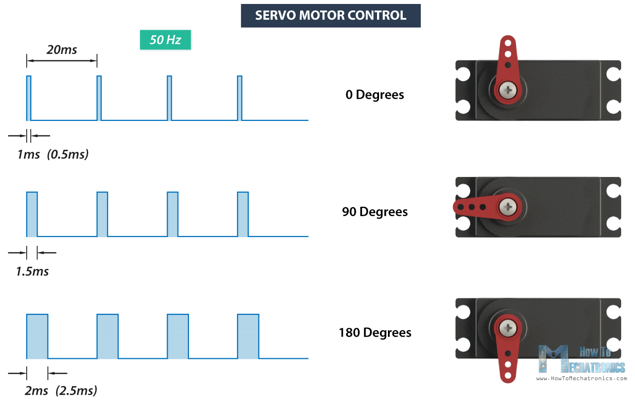
Generally pulses with 1ms duration correspond to 0 degrees position, 1.5ms duration to 90 degrees and 2ms to 180 degrees. Though the minimum and maximum duration of the pulses can sometimes vary with different brands and they can be 0.5ms for 0 degrees and 2.5ms for 180 degrees position.
Read More: Stepper Motors and Arduino – The Ultimate Guide
Popular RC / Hobby Servos for Arduino Projects
There are many different models and manufacturers of RC or hobby. The main consideration when choosing a servo motor is its torque, operating voltage, current draw and size.
Here are the two most popular servo models among makers, the SG90 Micro Servo and the MG996R.
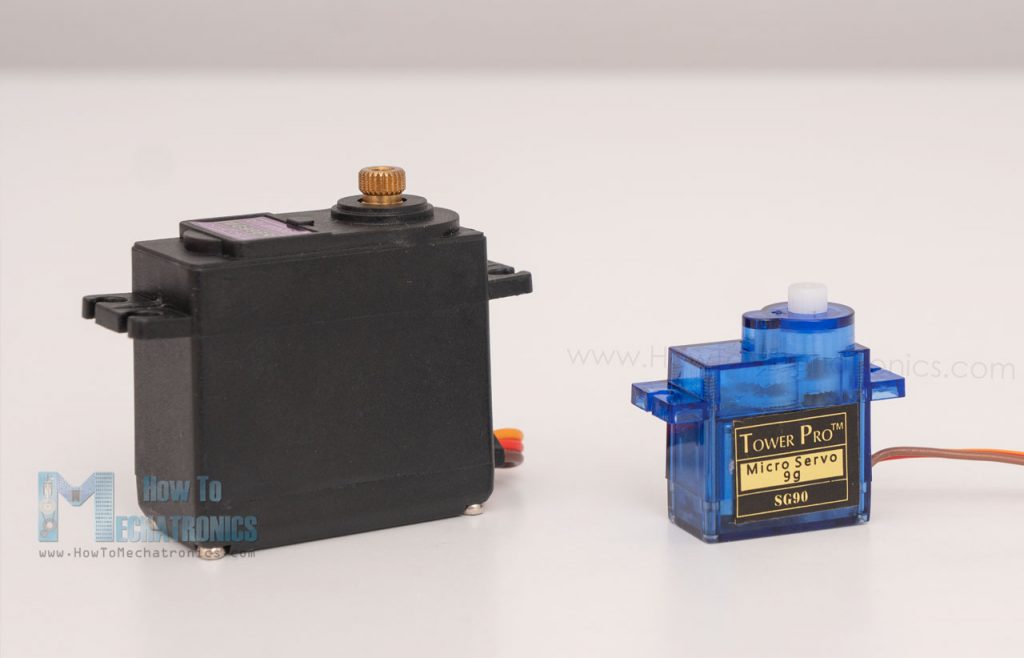
SG90 Micro Servo technical specifications:
| Stall Torque | 1.2kg·cm @4.8V, 1.6kg·cm @6V, |
| Operating Voltage | 3.5 – 6V |
| No Load Current | 100mA |
| Stall Current | 650mA |
| Max Speed | 60 degrees in 0.12s |
| Weight | 9g |
MG996R Servo technical specifications:
| Stall Torque | 11kg.cm @4.8v, 13kg.cm @6V |
| Operating Voltage | 4.8 – 7.2V |
| No Load Current | 220mA @4.8V, 250mA @6V |
| Stall Current | 650mA |
| Max Speed | 60 degrees in 0.20s |
| Weight | 55g |
Arduino Servo Motor Control
Let’s put the above said to test and make a practical example of controlling a hobby servo using Arduino. I will use the MG996R which is a high-torque servo featuring metal gearing with stall torque of 10 kg-cm. The high torque comes at a price and that’s the stall current of the servo which is 2.5A. The running current is from 500mA to 900mA and the operating voltage is from 4.8 to 7.2V.
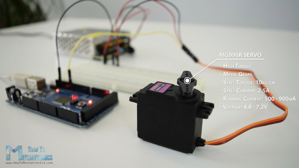
The current ratings indicate that we cannot directly connect this servo to the Arduino, but we must use a separate power supply for it.
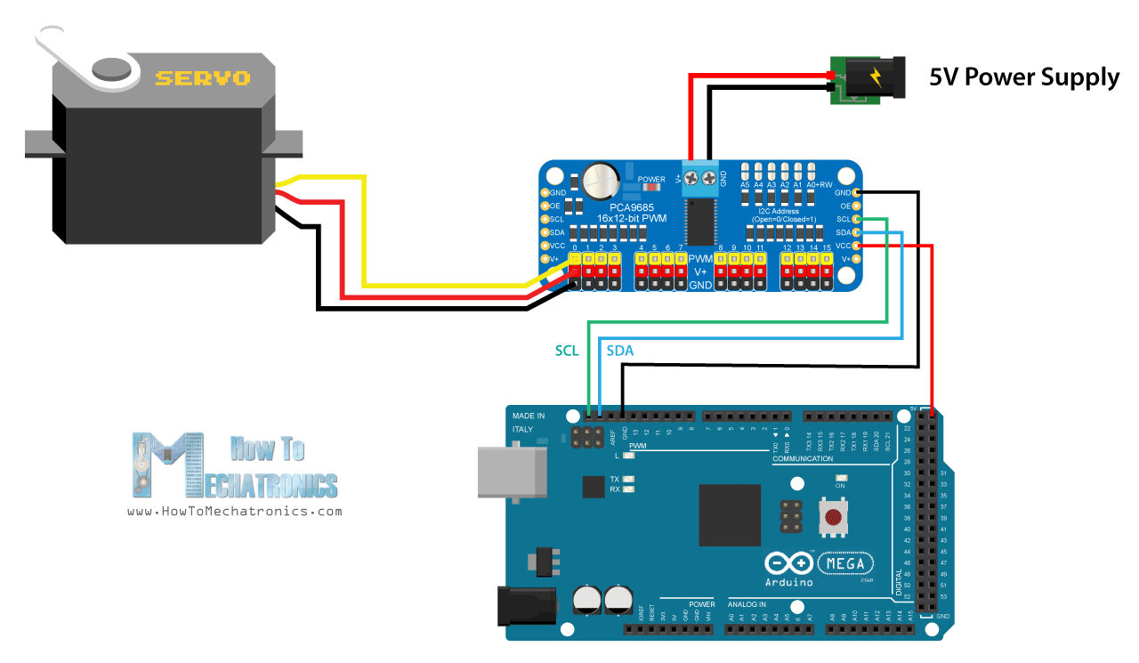
Circuit Diagram
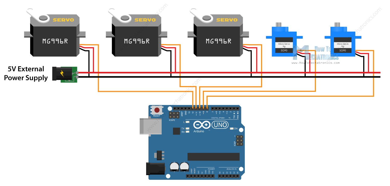
Here’s the circuit diagram for this example.
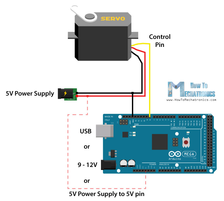
We simply need to connect the control pin of the servo to any digital pin of the Arduino board, connect the Ground and the positive wires to the external 5V power supply, and also connect the Arduino ground to the servo ground.
In case we use a smaller hobby servo, the S90 Micro Servo, it’s possible to power it directly from the 5V Arduino pin.
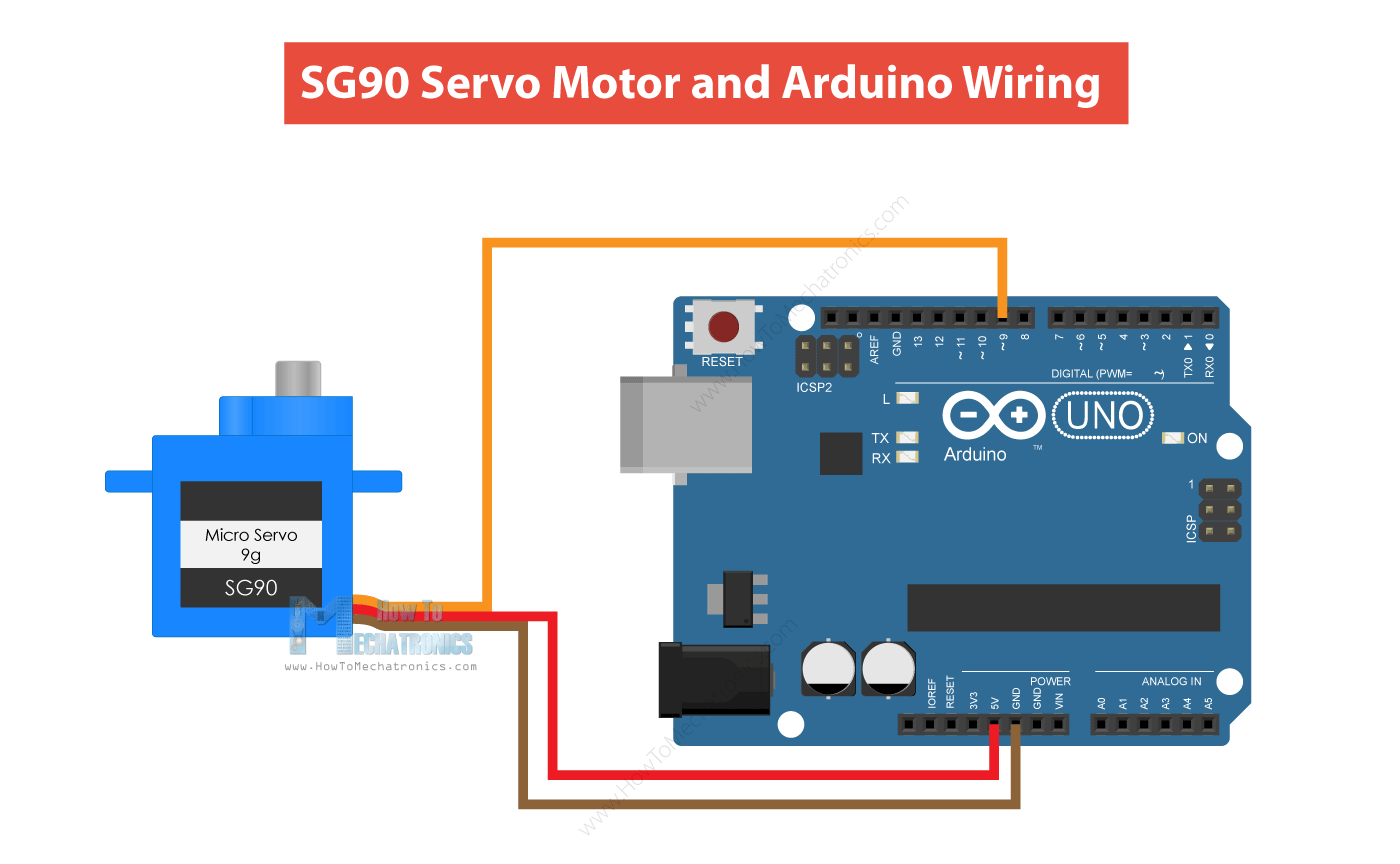
The S90 Micro Servo has lower current consumption, around 100-200mA no-load running current, but around 500-700mA stall current. On the other hand, the Arduino 5V pin can output only around 500mA if powered via USB, or up to 1A in powered via the barrel connector.
Even though it’s possible to run these 9g servo motors directly to Arduino, for more stable work I would suggest to always use an external power supply for them.
You can get the components needed for this example from the links below:
- MG996R Servo Motor …………………………. Amazon / Banggood / AliExpress
- or S90 Micro Servo ………..…………………… Amazon / Banggood / AliExpress
- Arduino Board ……………………………………. Amazon / Banggood / AliExpress
- 5V 2A DC Power Supply …………………..….. Amazon / Banggood / AliExpress
Disclosure: These are affiliate links. As an Amazon Associate I earn from qualifying purchases.
Servo Motor Control Arduino Code
Now let’s take a look at the Arduino code for controlling the servo motor. The code is very simple. We just need to define the pin to which the servo is connect, define that pin as an output, and in the loop section generate pulses with the specific duration and frequency as we explained earlier.
/*
     Servo Motor Control - 50Hz Pulse Train Generator
           by Dejan, https://howtomechatronics.com
*/

#define servoPin 9

void setup() {
  pinMode(servoPin, OUTPUT);
}

void loop() {
   // A pulse each 20ms
    digitalWrite(servoPin, HIGH);
    delayMicroseconds(1450); // Duration of the pusle in microseconds
    digitalWrite(servoPin, LOW);
    delayMicroseconds(18550); // 20ms - duration of the pusle
    // Pulses duration: 600 - 0deg; 1450 - 90deg; 2300 - 180deg
}Code language: PHP (php)
After some testing I came up with the following values for the duration of the pulses that work with my servo. Pulses with 0.6ms duration corresponded to 0 degrees position, 1.45ms to 90 degrees and 2.3ms to 180 degrees.
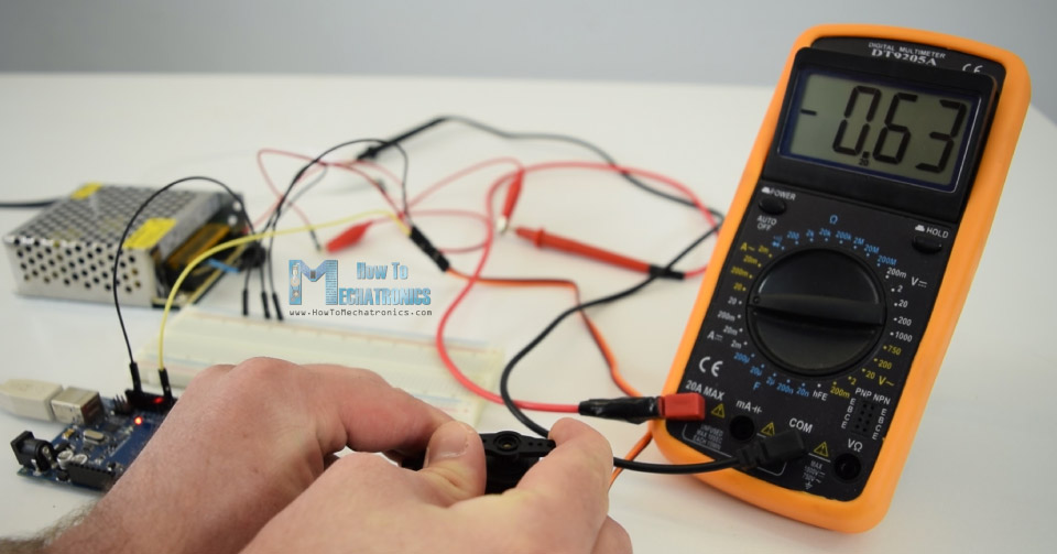
I connected a multimeter in series with the servo to check the current draw. The maximum current draw that I noticed was up to 0.63A at stall. Well that’s because this isn’t the original TowerPro MG996R servo, but a cheaper replica, which obviously has worse performance.
Nevertheless, let’s take a look at a more convenient way of controlling servos using Arduino. That’s using the Arduino servo library.
/*
     Servo Motor Control using the Arduino Servo Library
           by Dejan, https://howtomechatronics.com
*/

#include <Servo.h>

Servo myservo;  // create servo object to control a servo

void setup() {
  myservo.attach(9,600,2300);  // (pin, min, max)
}

void loop() {
  myservo.write(0);  // tell servo to go to a particular angle
  delay(1000);

  myservo.write(90);
  delay(500);

  myservo.write(135);
  delay(500);

  myservo.write(180);
  delay(1500);
}Code language: PHP (php)
Here we just need to include the library, define the servo object, and using the attach() function define the pin to which the servo is connected as well as define the minimum and maximum values of the pulses durations. Then using the write() function we simply set the position of the servo from 0 to 180 degrees.
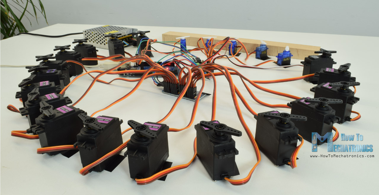
Controlling Multiple Servo Motors with Arduino
The Arduino servo library supports controlling of up to 12 servos at the same time with most the Arduino boards, and 48 servos using the Arduino Mega board. On top of that, controlling multiple servo motors with Arduino is as easy as controlling just a single one.
Here’s an example code for controlling multiple servos:
/*
     Controlling multiple servo motors with Arduino
     by Dejan, https://howtomechatronics.com
*/

#include <Servo.h>

Servo servo1;
Servo servo2;
Servo servo3;
Servo servo4;
Servo servo5;

void setup() {
  servo1.attach(8);
  servo2.attach(9);
  servo3.attach(10);
  servo4.attach(11);
  servo5.attach(12);
}

void loop() {
  // move all servos to position 0
  servo1.write(0);
  servo2.write(0);
  servo3.write(0);
  servo4.write(0);
  servo5.write(0);
  delay(2000);

  // move all servos to position 90
  servo1.write(90);
  servo2.write(90);
  servo3.write(90);
  servo4.write(90);
  servo5.write(90);
  delay(2000);

  // move all servos to position 180
  servo1.write(180);
  servo2.write(180);
  servo3.write(180);
  servo4.write(180);
  servo5.write(180);
  delay(2000);
}Code language: PHP (php)
So, we just have to create objects from the Servo class for each servo motor, and define to which Arduino pin is connected. Of course, we can set any servo to move to any position, at any time.
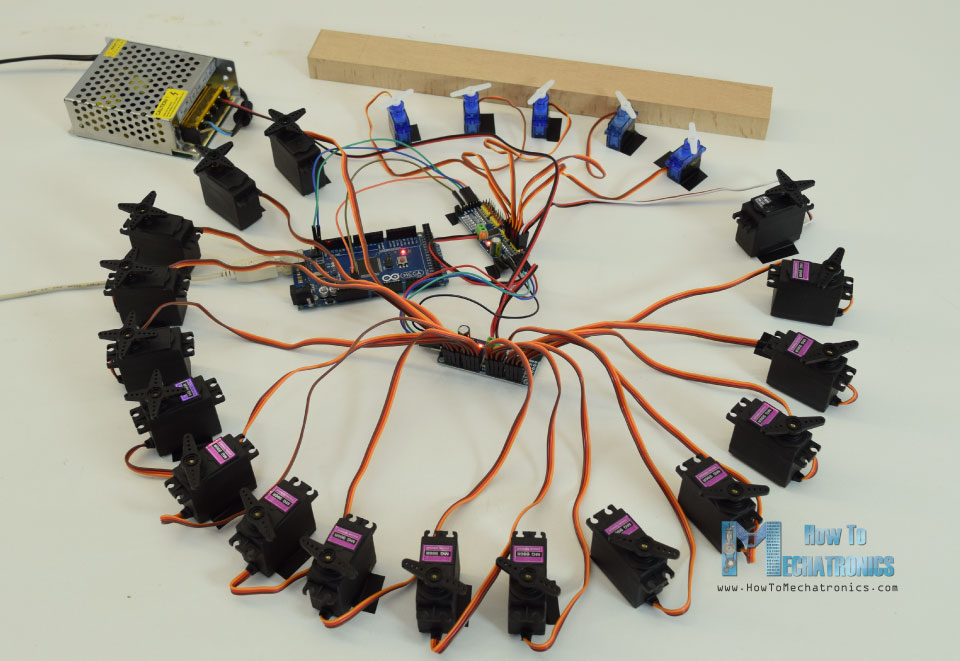
As an example you can also check my Arduino Ant Hexapod Robot project where I used an Arduino MEGA board to control 22 servo motors.
Arduino and PCA9685 PWM/ Servo Driver
There’s also another way of controlling servos with Arduino, and that’s using the PCA9685 servo driver. This is a 16-Channel 12-bit PWM and servo driver which communicates with Arduino using the I2C bus. It has a built in clock so it can drive 16 servos free running, or independently of Arduino.
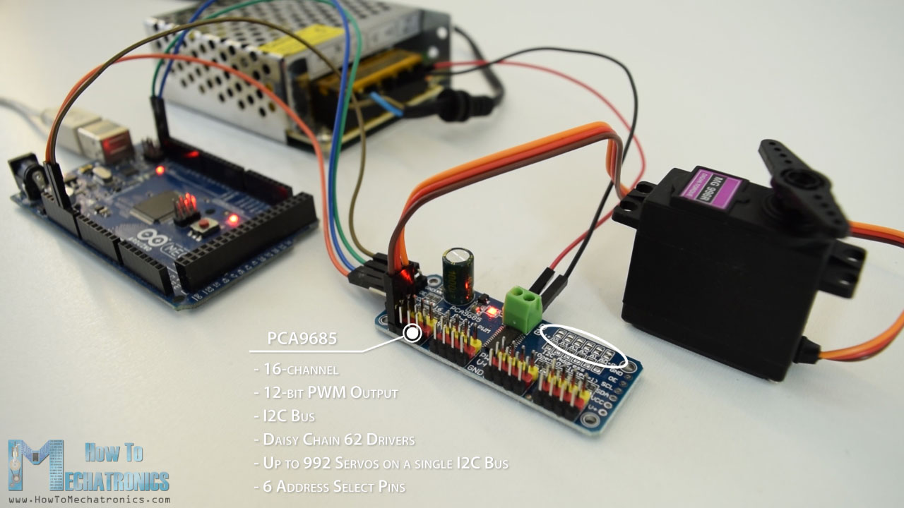
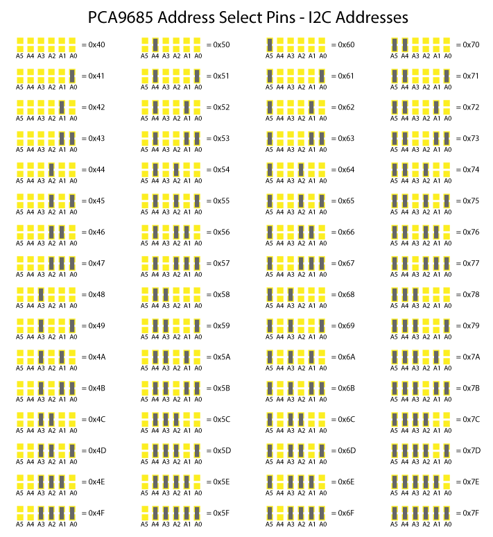
What’s even cooler we can daisy-chain up to 62 of these drivers on a single I2C bus. So theoretically we can control up to 992 servos using only the two I2C pins from the Arduino board. The 6 address select pins are used for setting different I2C addressed for each additional driver. We just need to connect the solder pads according to this table.
Here’s the circuit schematic and we can once again notice that we need a separate power supply for the servos.
You can get the components needed for this example from the links below:
- MG996R Servo Motor …………………………. Amazon / Banggood / AliExpress
- PCA9685 PWM Servo Driver ………………. Amazon / Banggood / AliExpress
- Arduino Board ……………………………………. Amazon / Banggood / AliExpress
- 5V 6A DC Power Supply …………………..….. Amazon / Banggood / AliExpress
Disclosure: These are affiliate links. As an Amazon Associate I earn from qualifying purchases.
Now let’s take a look at the Arduino code. For controlling this servo driver we will use the PCA9685 library which can be downloaded from GitHub.
Arduino and PCA9685 Code
/*
     Servo Motor Control using Arduino and PCA9685 Driver
           by Dejan, https://howtomechatronics.com

     Library: https://github.com/NachtRaveVL/PCA9685-Arduino
*/

#include <Wire.h>
#include "PCA9685.h"

PCA9685 driver;

// PCA9685 outputs = 12-bit = 4096 steps
// 2.5% of 20ms = 0.5ms ; 12.5% of 20ms = 2.5ms
// 2.5% of 4096 = 102 steps; 12.5% of 4096 = 512 steps
PCA9685_ServoEvaluator pwmServo(102, 470); // (-90deg, +90deg)

// Second Servo
// PCA9685_ServoEvaluator pwmServo2(102, 310, 505); // (0deg, 90deg, 180deg)


void setup() {
  Wire.begin();                 // Wire must be started first
  Wire.setClock(400000);        // Supported baud rates are 100kHz, 400kHz, and 1000kHz
  driver.resetDevices();        // Software resets all PCA9685 devices on Wire line

  driver.init(B000000);         // Address pins A5-A0 set to B000000
  driver.setPWMFrequency(50);   // Set frequency to 50Hz
}
void loop() {
  driver.setChannelPWM(0, pwmServo.pwmForAngle(-90));
  delay(1000);
  driver.setChannelPWM(0, pwmServo.pwmForAngle(0));
  delay(1000);
  driver.setChannelPWM(0, pwmServo.pwmForAngle(90));
  delay(1000);
}Code language: PHP (php)
So first we need to include the libraries and define the PCA9685 object. Then using the Servo_Evaluator instance define the pulses duration or the PWM output of the driver. Note that the outputs are 12-bit, or that’s a resolution of 4096 steps. So the minimum pulse duration of 0.5ms or 0 degrees position would correspond to 102 steps, and the maximum pulse duration of 2.5ms or 180 degrees position to 512 steps. But as explained earlier these values should be adjusted according your servo motor. I had value from 102 to 470 which corresponded to 0 to 180 degrees position.
In the setup section we need to define the I2C clock rate, set the driver address and set the frequency to 50Hz.
In the loop section, using the setChannelPWM() and pwmForAngle() functions we simply set the servo to the desired angle.
I connected a second servo to the driver, and as I expected, it wasn’t positioning the same as the first one, and that’s because the servos that I’m using are cheap copies and they are not so reliable. However, this isn’t a big problem because using the Servo_Evaluator instance we can set different output settings for each servo. We can also adjust the 90 degrees position in case it’s not precisely in the middle. In that way all servos will work the same and position at the exact angle.
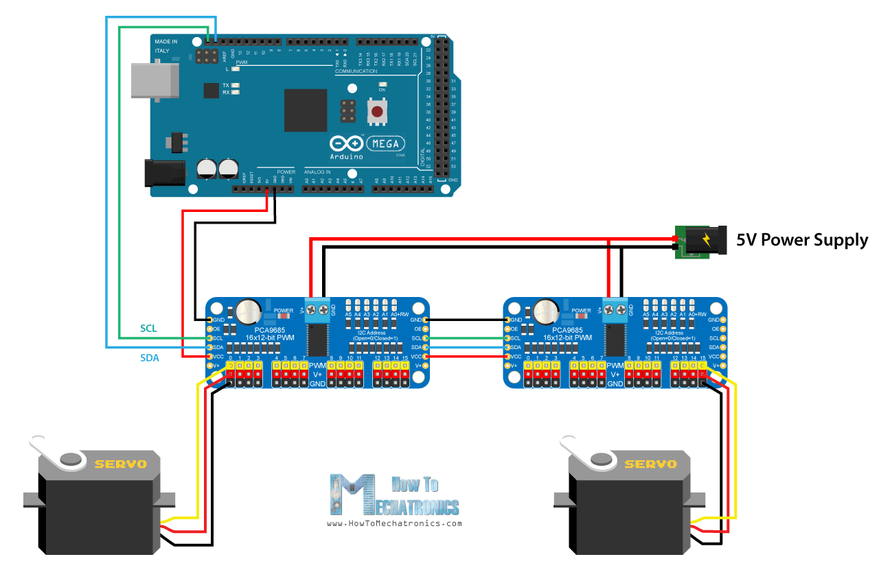
Controlling a lot of servos with Arduino and the PCA9685 drivers
We will take a look at one more example and that’s controlling a lot of servos with multiple chained PCA9685 drivers.
For that purpose we need to connect the drivers to each other and connect the appropriate address select solder pads. Here’s the circuit schematic:
Let’s take a look at the Arduino code now.
/*
     Servo Motor Control using Arduino and PCA9685 Driver
           by Dejan, https://howtomechatronics.com

     Library: https://github.com/NachtRaveVL/PCA9685-Arduino
*/

#include <Wire.h>
#include "PCA9685.h"

PCA9685 driver;

// PCA9685 outputs = 12-bit = 4096 steps
// 2.5% of 20ms = 0.5ms ; 12.5% of 20ms = 2.5ms
// 2.5% of 4096 = 102 steps; 12.5% of 4096 = 512 steps
PCA9685_ServoEvaluator pwmServo(102, 470); // (-90deg, +90deg)

// Second Servo
PCA9685_ServoEvaluator pwmServo2(102, 310, 505); // (0deg, 90deg, 180deg)


void setup() {
  Wire.begin();                 // Wire must be started first
  Wire.setClock(400000);        // Supported baud rates are 100kHz, 400kHz, and 1000kHz
  driver.resetDevices();        // Software resets all PCA9685 devices on Wire line

  driver.init(B000000);         // Address pins A5-A0 set to B000000
  driver.setPWMFrequency(50);   // Set frequency to 50Hz
}
void loop() {
  driver.setChannelPWM(0, pwmServo.pwmForAngle(-90));
  delay(1000);
  driver.setChannelPWM(0, pwmServo.pwmForAngle(0));
  delay(1000);
  driver.setChannelPWM(0, pwmServo.pwmForAngle(90));
  delay(1000);
}Code language: PHP (php)
So we should create separate PCA9685 object for each driver, define the addresses for each driver as well as set the frequency to 50Hz. Now simply using the setChannelPWM() and pwmForAngle() functions we can set any servo at any driver to position any angle we want.
Troubleshooting
Servo motor jitters and resets my Arduino board
This is a common problem with these hobby servo motors, the SG90 Micro Servo and the MG996R. The reason for this is that, as mentioned earlier, they can draw quite significant amount of current when they are at load. This can cause the Arduino board to reset, especially if you are powering the servo directly from the Arduino 5V pin.
In order to solve this issue you can use a capacitor across the GND and the 5V pin. It will act as a decouple capacitor which will provide additional current to the system at start up when the DC motor starts.
Servo motor won’t move entire range from 0 to 180 degrees
This is another common problem with these hobby servos. As we explained earlier, a pulse width of 1ms (0.5ms) corresponds to 0 degrees position, and 2ms (2.5ms) to 180 degrees. However, these values can vary from servo to servo and between different manufacturers.
In order to solve this problem, we need to adjust the pulse width we are sending to the servo motor with the Arduino. Luckily, using the Arduino Servo library we can easily adjust the pulse widths values in the attach() function.
The attach() function can take two additional parameters, and that’s the minimum and maximum pulse width in microseconds. The default values are 544 microseconds (0.544milliseconds) for minimum (0 degrees) angle, and 2400 microseconds (2.4ms). So by adjusting these values we can fine tune the moment range of the servo.
myservo.attach(9,600,2300); // (pin, min, max)Code language: JavaScript (javascript)Dimensions and 3D Model
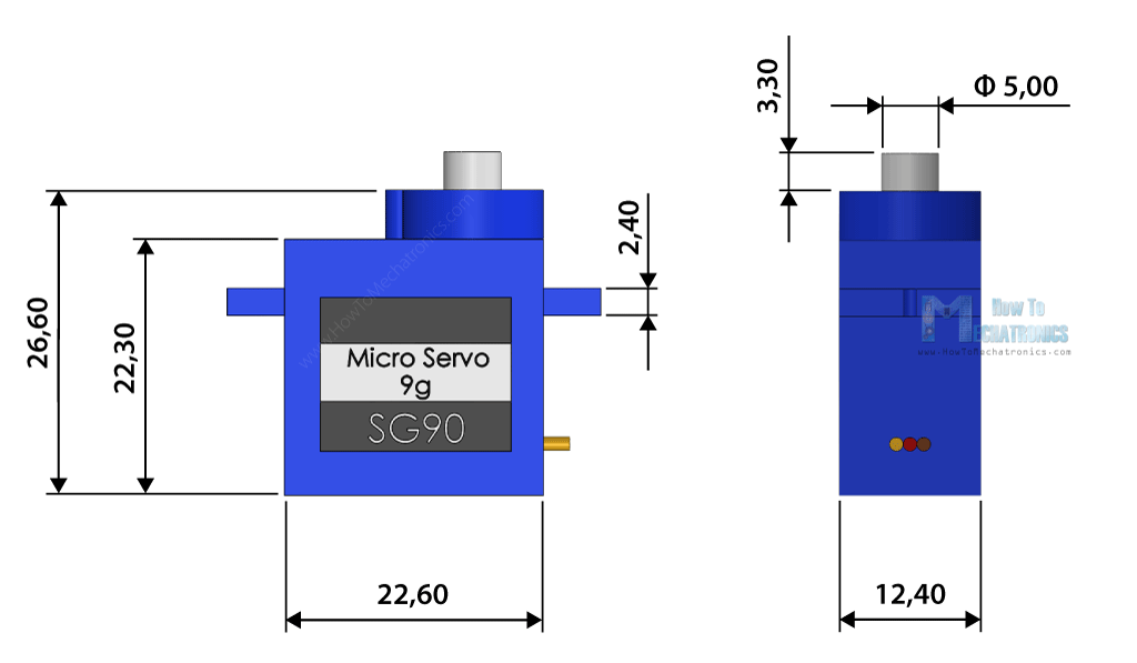
I made 3D models of the two most popular servo motors, the SG90 Micro Servo and the MG996R servo motor. You can download load them from the links below.
SG90 Micro Servo

3D Model: Download from Thangs.
Dimensions:
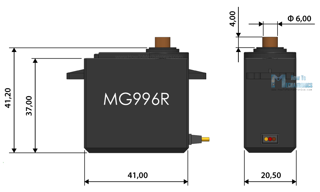
MG996R Servo Motor
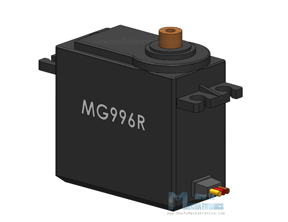
MG996R Servo Motor 3D Model: Download from Thangs.
Dimensions:
Conclusion
So, we have covered almost everything we need to know about using servo motors with Arduino. Of course, there are some many manufacturers and models of these type of hobby or RC servo motors, and each of them has its own unique features that might differ from what we explained above.
The possibilities for creating awesome robotics, automation and RC projects using motors are endless, however choosing the right model for your application is very important.
I hope you enjoyed this tutorial and learned something new. Feel free to ask any question in the comments section below, as well as make sure you can my Arduino Projects Collection.
Frequently Asked Questions (FAQs)
Using a servo motor with Arduino is quite easy. The servo motor has just 3 wires, two of which are GND and 5V for powering, and the third wire is the control line which goes to the Arduino board.
We can run servo motors directly from Arduino, but we might have power problems. If the servo motor draws more than 500mA of current, the Arduino board might lose it’s power and reset. It’s better to always use a separate power source for the servo motors.
Using the Arduino Servo library we can control up to 12 servo motors with most Arduino boards, and up to 48 servo motors with the Arduino Mega board. Of course, we need to use a dedicated power source for the servo motors.
Why is the last command of the first code having a value of:
delayMicroseconds(18550)? Is the 18550 value an error? I do not think the SG90 micro server can do more than 180 deg rotation. Could the MG996R Servo Motor do it?
/*
Servo Motor Control – 50Hz Pulse Train Generator
by Dejan, https://howtomechatronics.com
*/
#define servoPin 9
void setup() {
pinMode(servoPin, OUTPUT);
}
void loop() {
// A pulse each 20ms
digitalWrite(servoPin, HIGH);
delayMicroseconds(1450); // Duration of the pusle in microseconds
digitalWrite(servoPin, LOW);
delayMicroseconds(18550); // 20ms – duration of the pusle
// Pulses duration: 600 – 0deg; 1450 – 90deg; 2300 – 180deg
}
The 18550 it’s not an error. As explained, the frequency of the signal should be 50Hz or a pulse should occur each 20ms. 20ms is 20,000 microseconds. On the other hand the pusle duration defines the position of the servo, in this case the pulse duration is 1.45ms, or 1450 microseconds. So 20000-1450= 18550 microseconds. The pulse is 1450 microseconds HIGH, and the rest of the 20ms times is LOW, or 18550 microseconds LOW.
Hello, i have a question and i am appreciated if you can help me. The question is ,in this article, is this type of SG90 servo motor of the 180 degree? And if i use the 360 degree type,does it mean that i could not control the degree of the servo, i have read your project named ‘DIY CNC pan plotter’,and i want to figure out what’s the type of the servo motor in it.
thanks!
Hey, these are 180 degrees servos. We cannot control the position of the 360 degrees (continues rotation) servos, only their speed and direction.
This is a excellent website , i can find many usful article
good job , the way u have describe is very good
Glad you found it useful, thanks!
Dear Mechatronics,
I am writing with very quick question (to you might also seem like silly one) regarding your “How Servo Motors Work & How To Control Servos using Arduino” video on YouTube.
I am have just started working with Arduino and servos. Servos I went for ar exactly the same ones like yours in the video, which means that I also had to use external power source. Here is the challenge, I think I have used wrong powers source – because wires became hot. Please, would you mind sharing more information regarding power source you were using – and also how exacactly you have wired it up through the breadboard?
Power source I have used 220V to 5V at 15A
Bart
5V is the right power source, the amps rating doesn’t matter that are big in your case, it just means it can handle more servos working at the same time (depends on the servo current draw). The middle wire of the servo is 5V, the brown GND and the yellow is signal line.
Hello, I have also one query. I was using a 6V -7.4V Hobby king servo motor. Initially I was driving it with power source from arduino. Later I connected it with DC power supply at 7 V and I also set the current limit to max 700 mA to be at safer side but still my servo motor got destroyed. I wanted to know what was the reason and how can I correct it. Thanks
Hey, the the Arduino itself cannot power such a servo motor, it simply doesn’t provide that much power. Powering it with a separate power supply is correct, you said 7v, 700mA, which sounds reasonable and shouldn’t destroy the motor. The problem might be the servo itself, or maybe the 7V were too high and you should have tried with 6V max, but I couldn’t tell for sure.