In this Arduino tutorial we will learn how to connect and use an LCD (Liquid Crystal Display) with Arduino. LCD displays like these are very popular and broadly used in many electronics projects because they are great for displaying simple information, like sensors data, while being very affordable.
I’ve already used them in several of my Arduino projects, and you can check them out here:
- Arduino Security and Alarm System Project
- DIY Vending Machine – Arduino based Mechatronics Project
- Arduino Range Measurer and Digital Spirit Level Project
You can watch the following video or read the written tutorial below. It includes everything you need to know about using an LCD character display with Arduino, such as, LCD pinout, wiring diagram and several example codes.
What is LCD Character Display?
An LCD character display is a unique type of display that can only output individual ASCII characters with fixed size. Using these individual characters then we can form a text.
If we take a closer look at the display we can notice that there are small rectangular areas composed of 5×8 pixels grid. Each pixel can light up individually, and so we can generate characters within each grid.
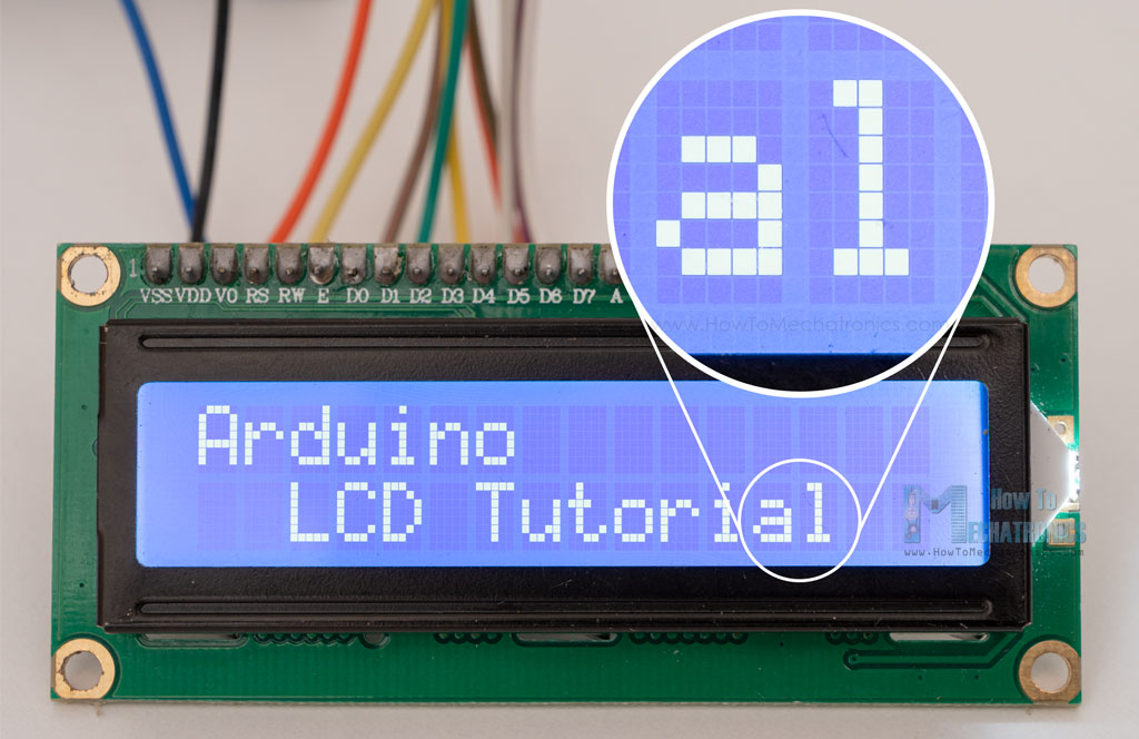
The number of the rectangular areas define the size of the LCD. The most popular LCD is the 16×2 LCD, which has two rows with 16 rectangular areas or characters. Of course, there are other sizes like 16×1, 16×4, 20×4 and so on, but they all work on the same principle. Also, these LCDs can have different background and text color.
16×2 LCD Pinout
It has 16 pins and the first one from left to right is the Ground pin. The second pin is the VCC which we connect the 5 volts pin on the Arduino Board. Next is the Vo pin on which we can attach a potentiometer for controlling the contrast of the display.
Next, The RS pin or register select pin is used for selecting whether we will send commands or data to the LCD. For example if the RS pin is set on low state or zero volts, then we are sending commands to the LCD like: set the cursor to a specific location, clear the display, turn off the display and so on. And when RS pin is set on High state or 5 volts we are sending data or characters to the LCD.
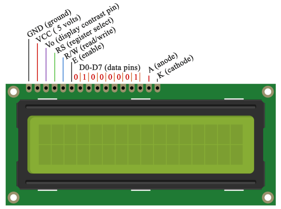
Next comes the R/W pin which selects the mode whether we will read or write to the LCD. Here the write mode is obvious and it is used for writing or sending commands and data to the LCD. The read mode is used by the LCD itself when executing the program which we don’t have a need to discuss about it in this tutorial.
Next is the E pin which enables the writing to the registers, or the next 8 data pins from D0 to D7. So through this pins we are sending the 8 bits data when we are writing to the registers or for example if we want to see the latter uppercase A on the display we will send 0100 0001 to the registers according to the ASCII table. The last two pins A and K, or anode and cathode are for the LED back light.
After all we don’t have to worry much about how the LCD works, as the Liquid Crystal Library takes care for almost everything. From the Arduino’s official website you can find and see the functions of the library which enable easy use of the LCD. We can use the Library in 4 or 8 bit mode. In this tutorial we will use it in 4 bit mode, or we will just use 4 of the 8 data pins.
How to Connect Arduino to LCD – Wiring Diagram
Here’s how we need to connect the 16×2 LCD display to an Arduino board.
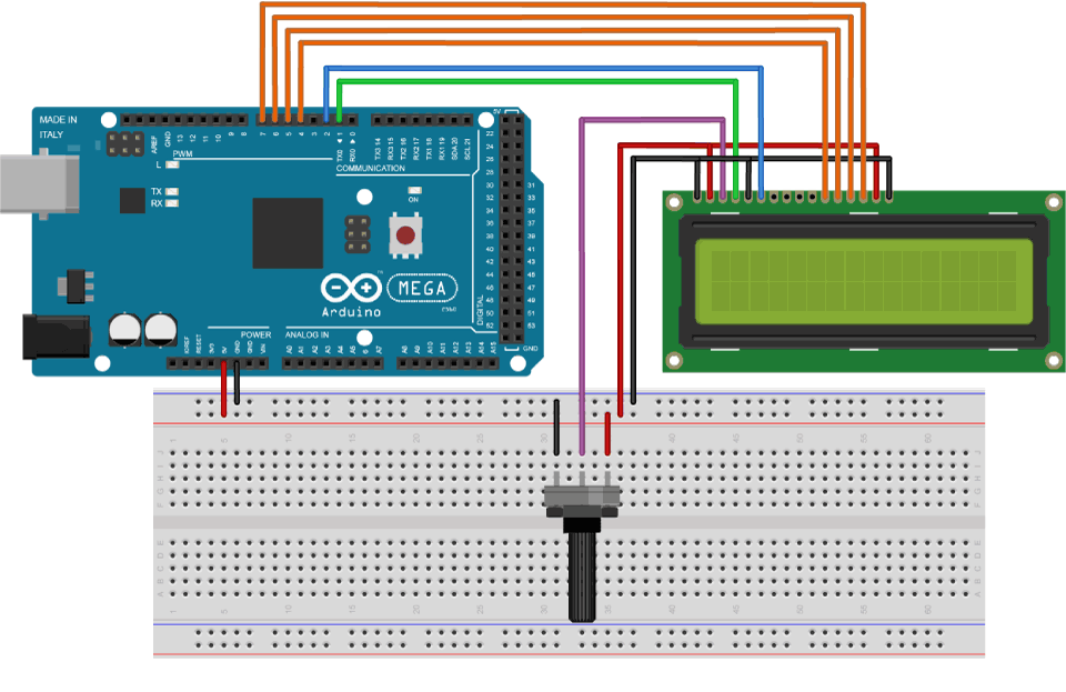
We will use just 6 digital input pins from the Arduino Board. The LCD’s registers from D4 to D7 will be connected to Arduino’s digital pins from 4 to 7. The Enable pin will be connected to pin number 2 and the RS pin will be connected to pin number 1. The R/W pin will be connected to Ground and the Vo pin will be connected to the potentiometer middle pin.
You can get these components from any of the sites below:
- 16×2 Character LCD…………………….. Amazon / Banggood / AliExpress
- Potentiometer ……………………………. Amazon / Banggood / AliExpress
- Arduino Board …………………………… Amazon / Banggood / AliExpress
- Breadboard and Jump Wires ……… Amazon / Banggood / AliExpress
Disclosure: These are affiliate links. As an Amazon Associate I earn from qualifying purchases.
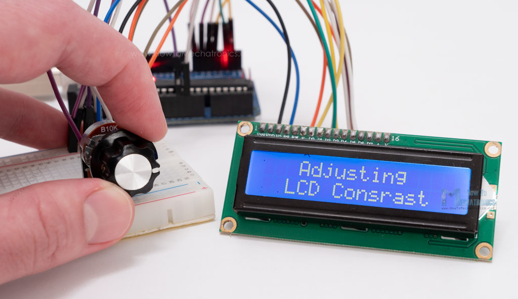
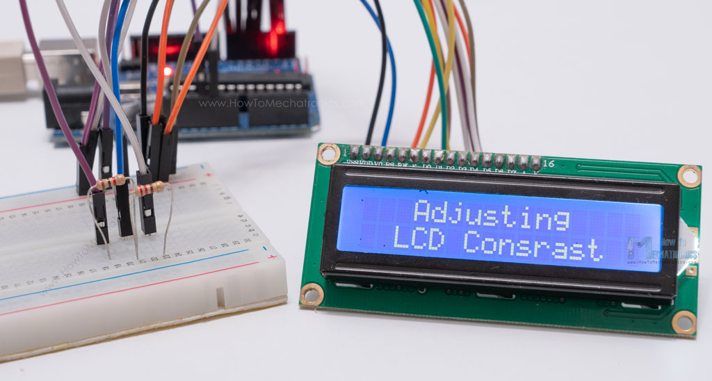
Adjusting the contrast of the LCD
We can adjust the contrast of the LCD by adjusting the voltage input at the Vo pin. We are using a potentiometer because in that way we can easily fine tune the contrast, by adjusting input voltage from 0 to 5V.
Can I use the LCD without Potentiometer?
Yes, in case we don’t have a potentiometer, we can still adjust the LCD contrast by using a voltage divider made out of two resistors. Using the voltage divider we need to set the voltage value between 0 and 5V in order to get a good contrast on the display. I found that voltage of around 1V worked worked great for my LCD. I used 1K and 220 ohm resistor to get a good contrast.
There’s also another way of adjusting the LCD contrast, and that’s by supplying a PWM signal from the Arduino to the Vo pin of the LCD. We can connect the Vo pin to any Arduino PWM capable pin, and in the setup section, we can use the following line of code:
analogWrite(11,100); // Generate PWM signal at pin D11, value of 100 (out of 255)Code language: JavaScript (javascript)It will generate PWM signal at pin D11, with value of 100 out of 255, which translated into voltage from 0 to 5V, it will be around 2V input at the Vo LCD pin.
LCD Arduino Code
Here’s a simple code through which we can explain the working principle of the Liquid Crystal library. This is the code of the first example from the video:
/*
* Arduino LCD Tutorial
*
* Crated by Dejan Nedelkovski,
* www.HowToMechatronics.com
*
*/

#include <LiquidCrystal.h> // includes the LiquidCrystal Library
LiquidCrystal lcd(1, 2, 4, 5, 6, 7); // Creates an LCD object. Parameters: (rs, enable, d4, d5, d6, d7)

void setup() {
 lcd.begin(16,2); // Initializes the interface to the LCD screen, and specifies the dimensions (width and height) of the display }
}

void loop() {
 lcd.print("Arduino"); // Prints "Arduino" on the LCD
 delay(3000); // 3 seconds delay
 lcd.setCursor(2,1); // Sets the location at which subsequent text written to the LCD will be displayed
 lcd.print("LCD Tutorial");
 delay(3000);
 lcd.clear(); // Clears the display
 lcd.blink(); //Displays the blinking LCD cursor
 delay(4000);
 lcd.setCursor(7,1);
 delay(3000);
 lcd.noBlink(); // Turns off the blinking LCD cursor
 lcd.cursor(); // Displays an underscore (line) at the position to which the next character will be written
 delay(4000);
 lcd.noCursor(); // Hides the LCD cursor
 lcd.clear(); // Clears the LCD screen
}Code language: PHP (php)
Code description:
First thing we need to do is it insert the Liquid Crystal Library. We can do that like this: Sketch > Include Library > Liquid Crystal. Then we have to create an LC object. The parameters of this object should be the numbers of the Digital Input pins of the Arduino Board respectively to the LCD’s pins as follow: (RS, Enable, D4, D5, D6, D7). In the setup we have to initialize the interface to the LCD and specify the dimensions of the display using the begin() function.
In the loop we write our main program. Using the print() function we print on the LCD.
lcd.print("Arduino"); // Prints "Arduino" on the LCDCode language: PHP (php)The setCursor() function is used for setting the location at which subsequent text written to the LCD will be displayed.
lcd.setCursor(2,1); // Sets the location at which subsequent text written to the LCD will be displayed Code language: JavaScript (javascript)The blink() function is used for displaying a blinking cursor and the noBlink() function for turning off.
lcd.blink(); //Displays the blinking LCD cursorCode language: JavaScript (javascript)The cursor() function is used for displaying underscore cursor and the noCursor() function for turning off. Using the clear() function we can clear the LCD screen.
lcd.clear(); // Clears the LCD screenCode language: JavaScript (javascript)Scrolling text example on 16×2 LCD and Arduino
In case we have a text with length greater than 16 characters, we can scroll the text using the scrollDisplayLeft() or scrollDisplayRight() function from the LiquidCrystal library.
Here’s an example code:
#include <LiquidCrystal.h>

LiquidCrystal lcd(1, 2, 4, 5, 6, 7); // Creates an LCD object. Parameters: (rs, enable, d4, d5, d6, d7)

void setup() {
  lcd.begin(16, 2);
  lcd.print("Scrolling Text Example");
}
void loop() {
  lcd.scrollDisplayLeft();
  delay(500);
}Code language: PHP (php)
We can choose whether the text will scroll left or right, using the scrollDisplayLeft() or scrollDisplayRight() functions. With the delay() function we can set the scrolling speed.
If you want more control over how the text is scrolling, you could also make the scrolling on your own using a “for” loop. Here’s an example:
#include <LiquidCrystal.h>

LiquidCrystal lcd(1, 2, 4, 5, 6, 7); // Creates an LCD object. Parameters: (rs, enable, d4, d5, d6, d7)

void setup() {
  lcd.begin(16, 2); // Initializes the interface to the LCD screen, and specifies the dimensions (width and height) of the display

}

void loop() {
  // scroll text to the right
  for (int i = 0; i <= 13; i++) {
    lcd.setCursor(i, 0); // Sets the location at which subsequent text written to the LCD will be displayed
    lcd.print("LCD");
    delay(500); // 1 second delay
    lcd.clear(); // Write a character to the LCD
  }
  // scroll text to the left
  for (int i = 12; i >= 1; i--) {
    lcd.setCursor(i, 0);
    lcd.print("LCD");
    delay(500);
    lcd.clear();
  }
}Code language: PHP (php)
How to Generate and Display Custom Characters on the LCD
In addition to the ASCII characters, with the LiquidCrystal library it is also possible to generate and display custom characters on the LCD.
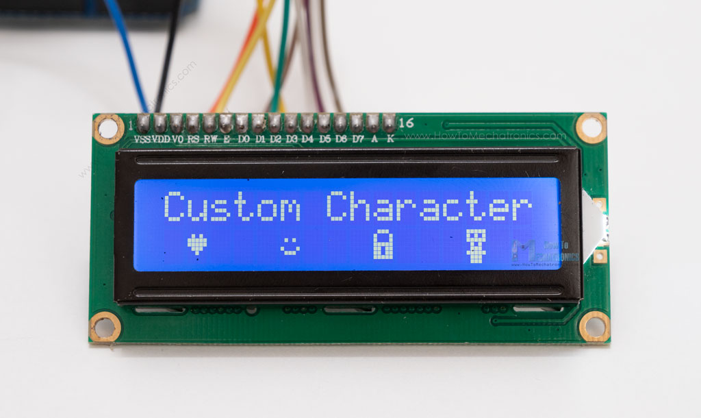
We can specify the appearance of each character by an array of 8 bytes. Here’s an example code:
#include <LiquidCrystal.h>

byte heart[8] = {  // Array of bytes
  B00000,          // B stands for binary formatter and the five numbers are the pixels
  B01010,
  B11111,
  B11111,
  B01110,
  B00100,
  B00000,
  B00000
};

byte smile[8] = {
  B00000,
  B00000,
  B01010,
  B00000,
  B10001,
  B01110,
  B00000,
  B00000
};

byte lock[8] = {
  B01110,
  B10001,
  B10001,
  B11111,
  B11011,
  B11011,
  B11111,
  B00000
};

byte character[8] = {
  B11111,
  B10101,
  B11111,
  B01010,
  B01110,
  B11111,
  B01110,
  B01110
};


LiquidCrystal lcd(1, 2, 4, 5, 6, 7); // Creates an LC object. Parameters: (rs, enable, d4, d5, d6, d7)

void setup() {
  lcd.begin(16, 2); // Initializes the interface to the LCD screen, and specifies the dimensions (width and height) of the display
  lcd.createChar(0, heart); // Create a custom character
  lcd.createChar(1, smile);
  lcd.createChar(2, lock);
  lcd.createChar(3, character);

  // Clears the LCD screen
  lcd.clear();

  // Print a message to the LCD
  lcd.print("Custom Character");
}

void loop() {
  lcd.setCursor(1, 1);
  lcd.write(byte(0));  // Display the custom character 0, the heart

  lcd.setCursor(5, 1);
  lcd.write(byte(1));

  lcd.setCursor(9, 1);
  lcd.write(byte(2));

  lcd.setCursor(13, 1);
  lcd.write(byte(3));
}Code language: PHP (php)
We can notice how we can specify the appearance of the character by changing the 0s into 1s within the 5×8 pixels grid.
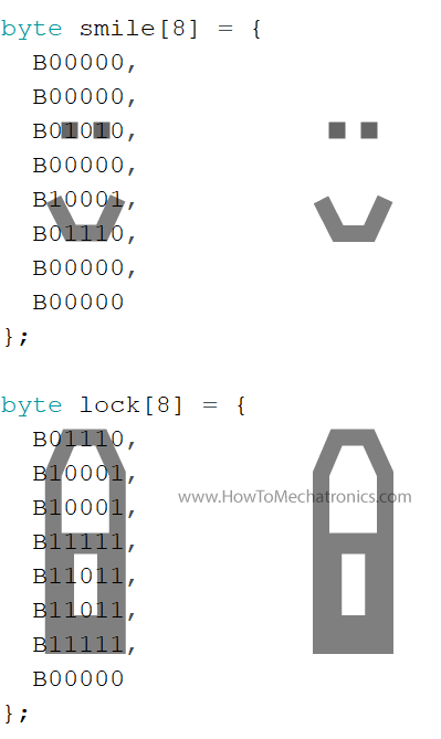
In the setup we have to create the custom character using the createChar() function.
lcd.createChar(0, heart); // Create a custom characterCode language: JavaScript (javascript)The first parameter in this function is a number between 0 and 7, or we have to reserve one of the 8 supported custom characters. The second parameter is the name of the array of bytes.
We write the custom character to the display using the write() function and as a parameter we use the number of the character.
lcd.write(byte(0)); // Display the custom character 0, or the heartCode language: JavaScript (javascript)See also: Arduino Touch Screen Tutorial | TFT LCD
Conclusion
So, we have covered pretty much everything we need to know about using an LCD with Arduino. These LCD Character displays are really handy for displaying information for many electronics project. In the examples above I used 16×2 LCD, but the same working principle applies for any other size of these character displays.
I hope you enjoyed this tutorial and learned something new. Feel free to ask any question in the comments section below and don’t forget to check out my full collection of 30+ Arduino Projects.
Hello! I know it is late but I have to ask this question, my lcd only shows blue screen I checked wires tons of times and tried to adjust potentiometer but not works. I hope you could help me
Hey, well you have already tried the recommended things when it comes to that problem, only blue screen. Very often it’s problem with the contrast, but you said you have tried with a potentiometer. Try also by making a 3.3v voltage divider using two resistors. Also the problem might be something else, maybe your LCD have a different driver on its board that might not be compatible with this example, I don’t know, maybe. Or maybe, your LCD is faulty one.
I GREATLY appreciate the help to be able to understand how to use the the LCD!
For those who don’t have a potentiometer, the potentiometer is optional, you can use ‘analogWrite()’ function:
void setup() {
some code here;
analogWrite(your VO pin, 50);
some code here too;
}
why use potentiometer, can i remove potentiometer?
Yes, you can remove it, but you will need to set two resistors as a voltage dividers to get the proper voltage for getting the proper contrast of the LCD.
how do you make the voltage divider and what are the values of the resistors?
Really appreciate your work!
Have no experience with writing code but you have made it easier to understand the basics, TY Dejan!
I’m glad to hear this. Thanks.
I made it ! finally, it is working !
But you should not connect Anode to Vcc directly, since there is a LED, so may burn it. You need a resistor of 220 Ohm, and you can increase the resistance of you want a dimmer backlight. I connected my resistor to a PMW port to control the backlight from the code.
Great, connecting the backlight control to a PMW port and a resistor is cool idea.
can we print something permanently , I mean its displayed again on the LCD after reboot the LCD ?
and never changed again until you run the programming again ?
Not really, you can print something permanently, but sure you can make a code that would display what you want even after rebooting the LCD, for example, using the EEPROM of the Arduino which can store data when the power is off.
sir, if use I2c, what the codes ?
It would be different. I don’t have that code.
avrdude: ser_open(): can’t open device “\\.\COM13”: The system cannot find the file specified.
There’s an error. How to fix this.
Check what’s your COM Port number.
Strange to use the D1 pin,
is that wanted or specific to RS LCD functionalism ?
Why put code that doe’s not compile…???
The code is working properly. You might be doing something wrong. What error do you get?
thank you so much! i have learn’t so much better with hands on and you made it perfect for me ! thanks again!!!
I’m glad to hear that. You are welcome!
I highly appreciate that your video for LCD. I like to know whether you have upload video for LCD though I2C module?. if so kindly pass me a link (URL)
Thanks. Sorry but I don’t have such a tutorial yet.