Have you ever wondered about the quality of the air you are breathing, or maybe, why you sometimes feel sleepy in the office or tired in the morning even after sleeping all night? Poor air quality can lead to many negative health effects as well as can cause tiredness, headaches, loss of concentration, increased heart rate and so on. Monitoring the quality of the air may actually be more important than you realize. So, in this tutorial we will learn how to build our own Air Quality Monitor which is capable of measuring PM2.5, CO2, VOC, Ozone, as well as temperature and humidity.
You can watch the following video or read the written tutorial below.
Overview
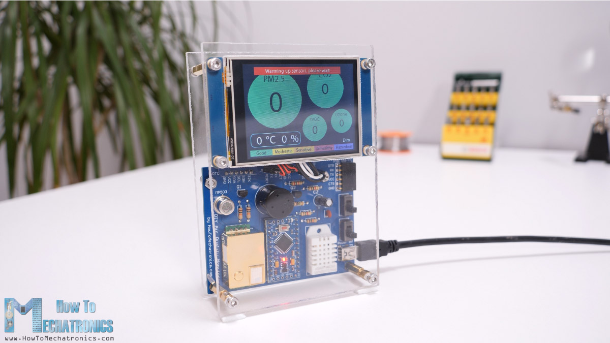
I will explain how each of air quality parameters affect us and how the sensors work. The brain of this project is an Arduino Pro Mini board which in combination with a 2.8” Nextion touch display provides a decent user interface.
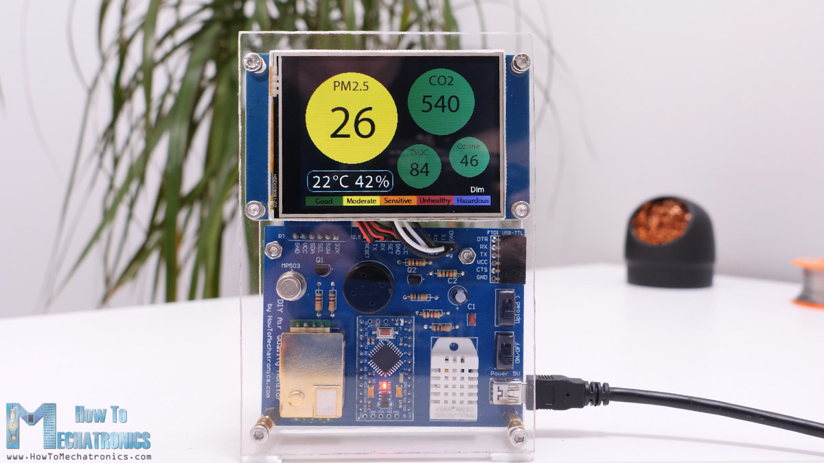
We can see the measurements from all the sensors in real time, and if we click on a particular sensor, we will get values from the last 24 hours from that sensor. There’s also a dimming function through which we can lower the brightness of the display or even turn it off completely. This is convenient, for example, if we want to track the air quality in our bedroom during the night.
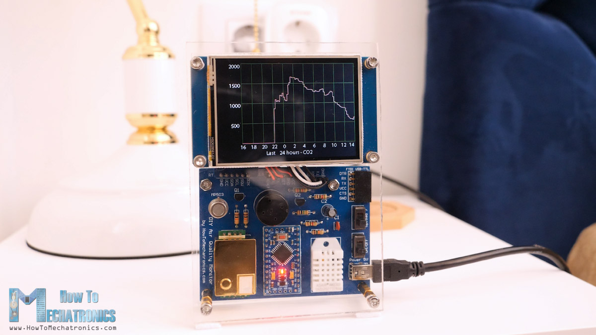
We can turn off the screen for the night, and the next day we can check the values from each sensor individually.
Nevertheless, now I will walk you through the entire process of building it and explain how everything works. At the end of this video, you will be able to build one on your own. So, let’s get started.
The PM2.5 Sensor – PMS5003
This device has four main components or air quality sensors. We are using the PMS5003 sensor for measuring PM2.5 or particulate matter in the air with diameter of around 2.5 microns. Particulates are the most harmful form of air pollution because they can penetrate deep into the lungs, blood streams and brain, causing many health problems.
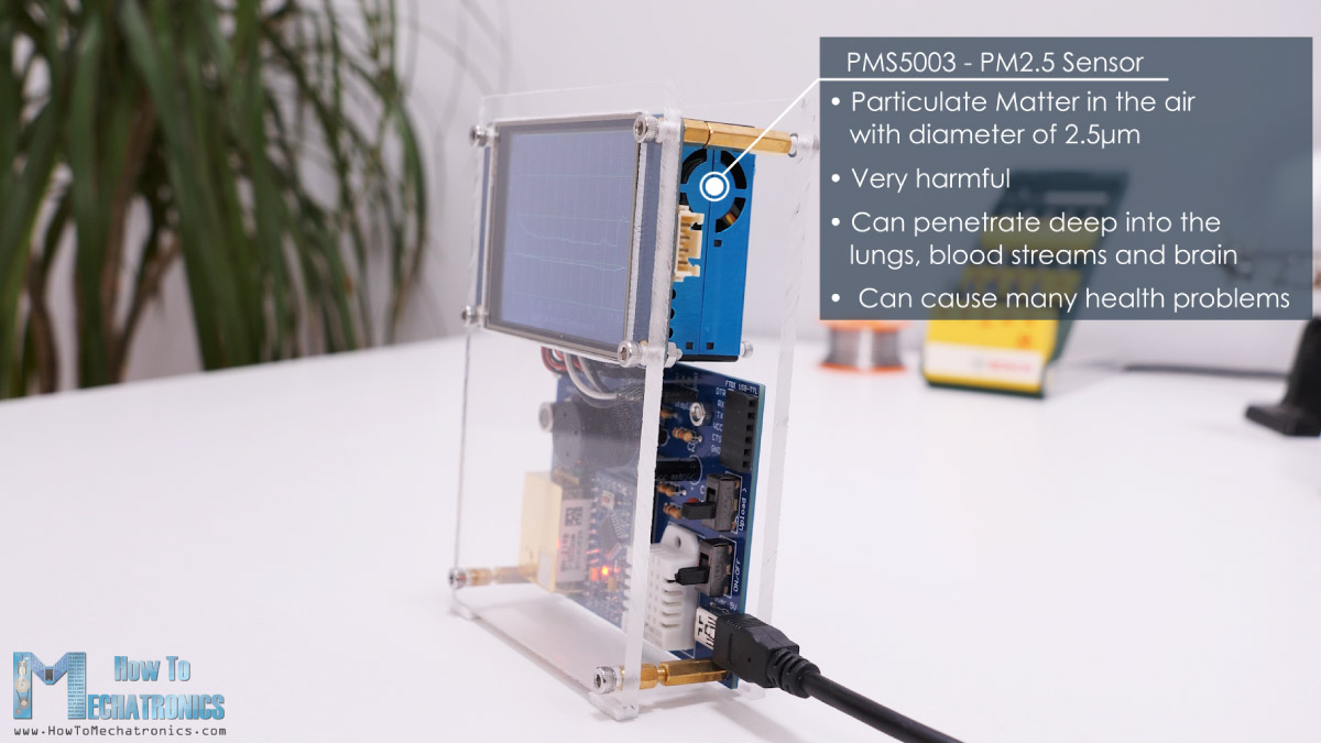
This sensor works on the principle of laser scattering. The sensor has a fan which creates a controlled airflow so the environmental particulates pass through a focused laser beam.
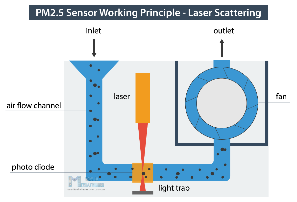
The particulates cause light scattering which is detected by a photodiode and then converted into PM concentration with the help of its microprocessor. I found the results of this sensor to be quite reliable and along PM2.5 it can also output PM1 and PM10 values.
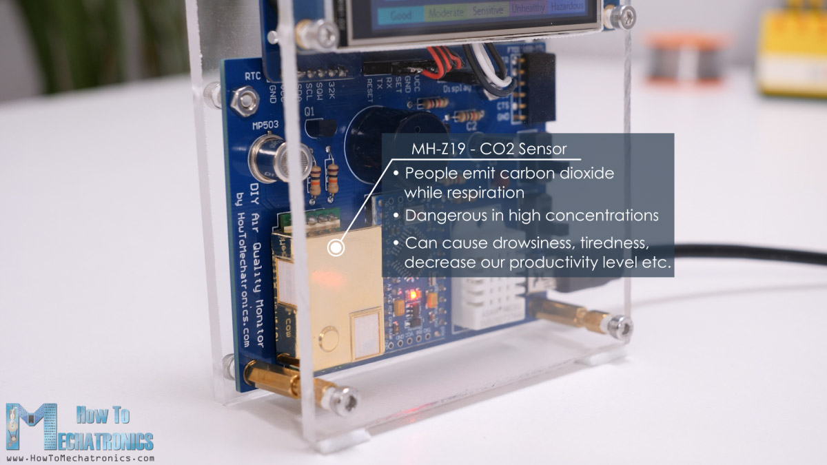
The CO2 Sensor – MH-Z19
Next, we are using the MH-Z19 sensor for measuring CO2 or carbon dioxide. As people emit carbon dioxide while respiration, the indoor concentration of CO2 can easily get very high. CO2 is not only dangerous in high concentrations, but it can also cause drowsiness, tiredness, decrease our productivity level and so on.
The sensor is using non-dispersive infrared principle for measuring CO2 in the air. An infrared source directs light through a tube which is filled with the air that we are measuring. On the other side of the infrared source, there is an optical filter and an IR detector which measures the amount of IR light that passes through.
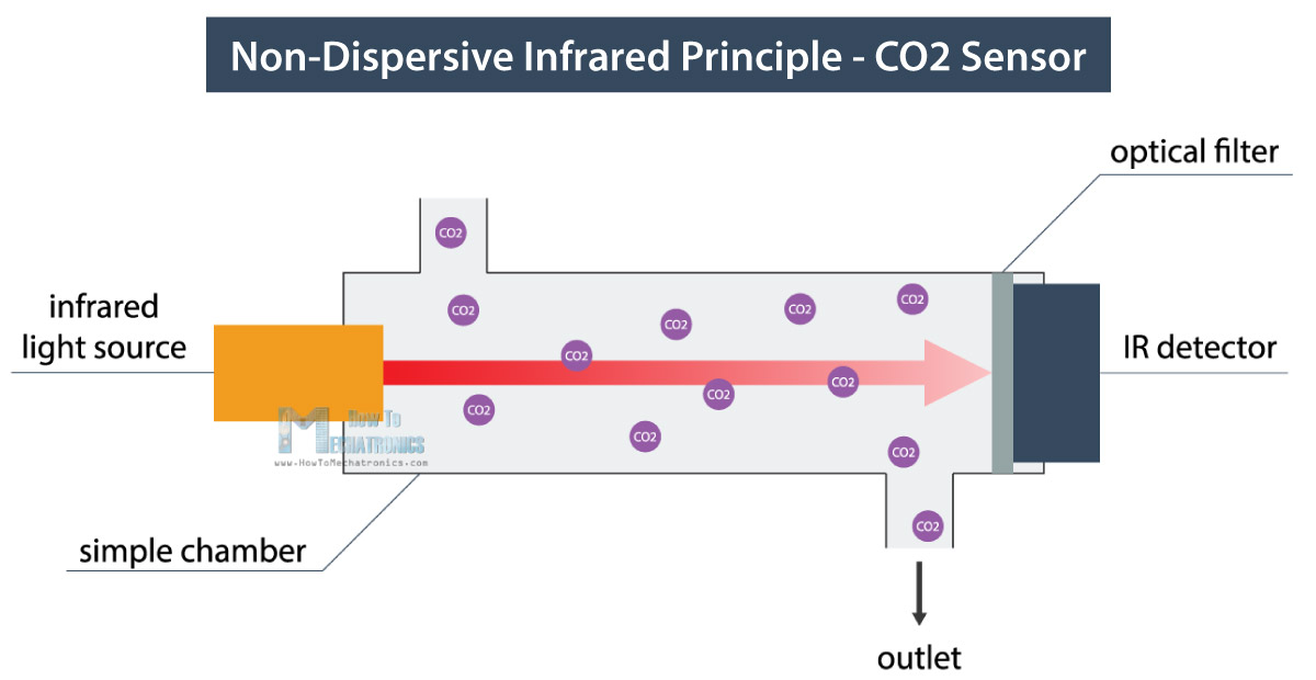
The CO2 gas molecules which are present in the air that we are measuring absorb a specific band of IR light while letting some wavelengths to pass through. So, the CO2 level is calculated according difference between the amount of light emitted and the amount of IR light received by the detector. The results from this sensor are also quite accurate.
The VOC and Ozone Sensors – MP503 and MQ-131
For measuring VOC and Ozone we are using the MP503 and the MQ131 gas sensors. These are heated metal oxide sensors and their principle of work is based on detecting change in resistance at the presence of targeted gases.
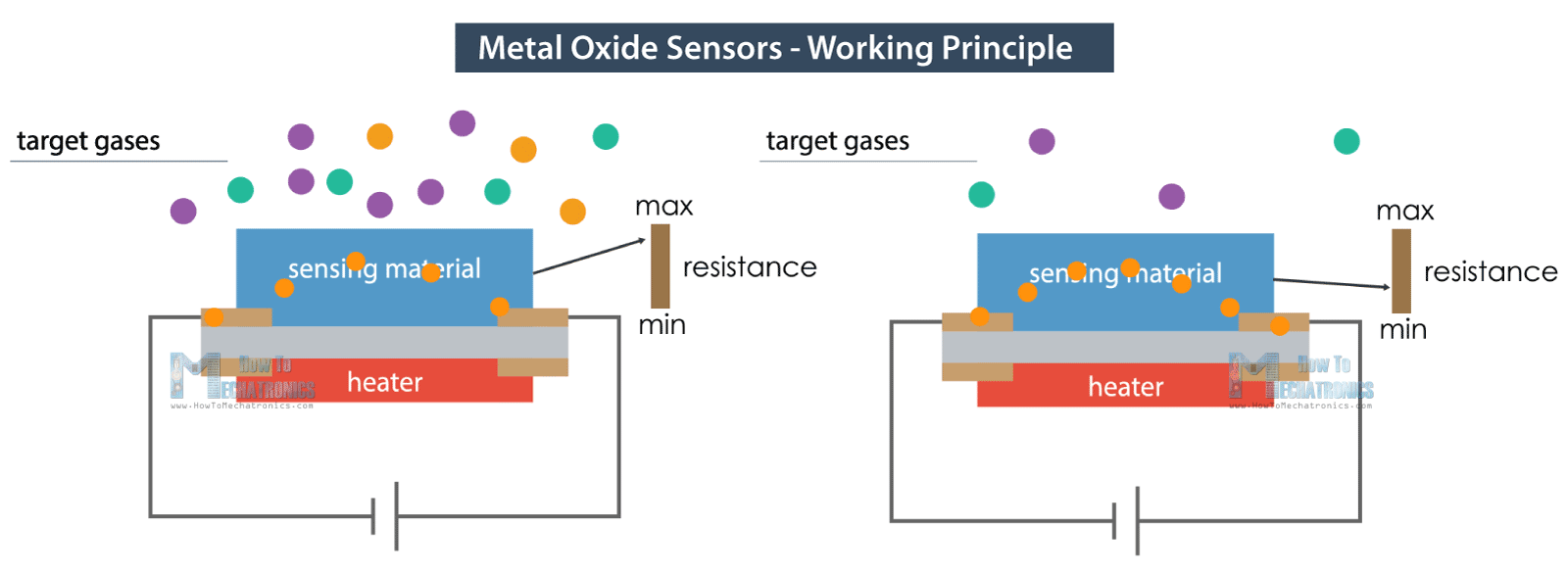
A specific electrical current pass through a metal substrate and the resistance changes according to the amount of gas present.
The target gas of the MQ131 sensor is just Ozone, which in a normal household can be generated by products like certain air purifiers, facial steamers, germicidal lamps that produce ultraviolet light and so on.
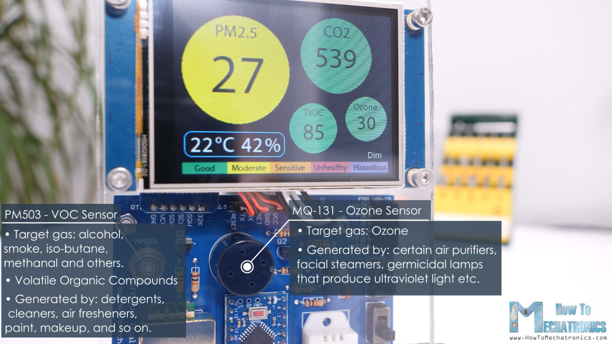
On the other hand, the MP503 sensor has multiple target gases, including alcohol, smoke, iso-butane, methanal and others. VOC stands for Volatile Organic Compounds and these are organic emission from products that we use on a daily basis like laundry detergents, cleaners, air fresheners, paint, makeup, and so on. VOCs can cause many negative health effects including headaches, irritation to eyes, skin reactions, dizziness and so on.
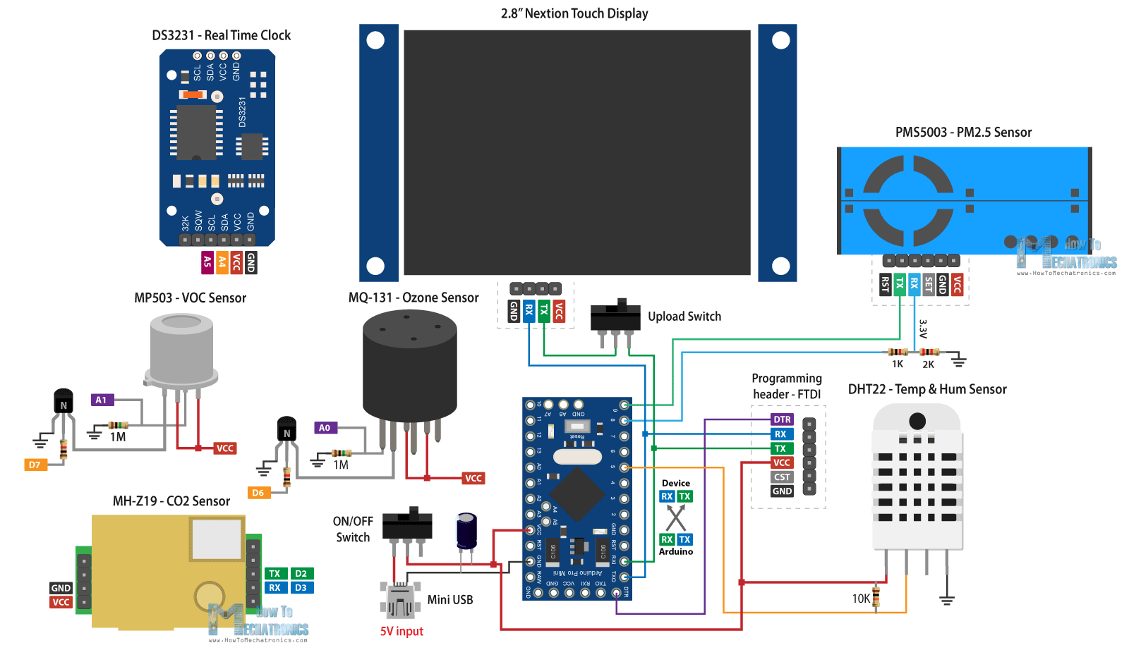
DIY Arduino Air Quality Monitor – Circuit Diagram
Nevertheless, so let’s take a look at the circuit diagram now and explain how everything needs to be connected.
You can get the components needed for this Arduino air quality monitor from the links below:
- PMS5003 PM Sensor ……………………. Amazon / Banggood / AliExpress
- MH-Z19 CO2 Sensor …………………….. Amazon / Banggood / AliExpress
- MQ-131 Ozone Sensor ………………….. Amazon / Banggood / AliExpress
- MP503 VOC Sensor ………………………. Amazon / Banggood / AliExpress
- DHT22 Temp & Hum Sensor…………. Amazon / Banggood / AliExpress
- Nextion 2.8″ Display …………………….. Amazon / Banggood / AliExpress
- DS3231 RTC …………………………………. Amazon / Banggood / AliExpress
- Arduino Pro Mini………………..…….….. Amazon / Banggood / AliExpress
- Distance / Spacer Nuts M3 …………… Amazon / Banggood / AliExpress
- Mini USB Connector ……………………. Amazon / Banggood / AliExpress
- Pin headers …………………………………. Amazon / Banggood / AliExpress
- 2 Positions switch ………………………… Amazon / Banggood / AliExpress
- Capacitors values: 0.1uF ceramic and 10uF electrolytic
- Transistors – 2N3904
- Switch
Disclosure: These are affiliate links. As an Amazon Associate I earn from qualifying purchases.
Correct resistors values: R1 = 1K, R2 = 2K, R6=100K or 1M, R7=1K
The PM2.5 sensor communicates with the Arduino through a serial interface. It works at 5V, but the receive RX logic level works at 3.3v, so therefore we need a voltage divider for it. The CO2 sensor and the Nextion display also use serial communication. For reading the VOC and the Ozone sensors we use analog inputs of the Arduino, while the DHT22 temperature and humidity sensor uses a digital pin for that purpose.
The two transistors are used for activating the sensors heaters. We are also using a Real Time Clock module for keeping track of the time when storing the sensors values, and it uses the I2C communication. The whole device is powered with 5V through a Mini USB connector.
See also: The 8 Best Arduino Starter Kits [2021 Update]
Now if we try to connect everything together, we will get quite a mess because of the many connections.
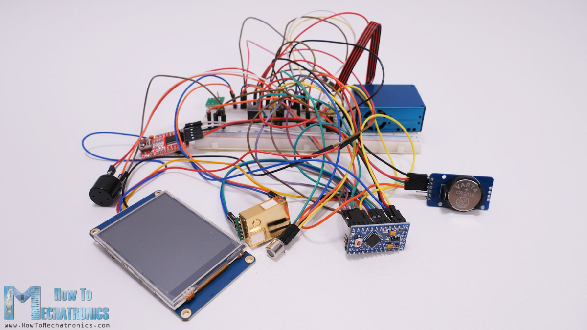
So, we definitely need a PCB for this project.
Making a PCB for the Arduino Air Quality Monitor
For making a PCB for this project, I’m going to use Altium Designer which are actually the sponsor of this video.
Altium Designer represents decades of innovation and development dedicated to creating a truly unified design environment. Striking the perfect balance between power and ease of use, Altium Designer has secured its position as the most widely-used PCB design solution on the market.
Now I will show you how I designed the PCB for this project using Altium Designer. I started with making the schematic for the project. Altium Designer has built-in libraries with basic electronic components, but even better you can search for components directly from manufacturers which makes sourcing components for your project very convenient.
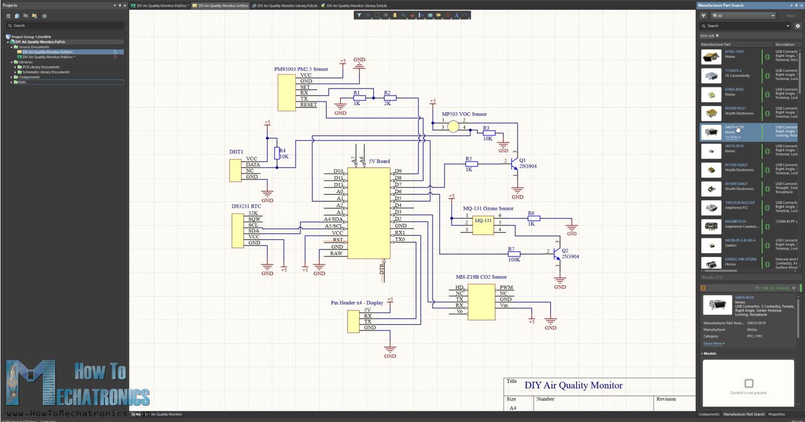
As an example, I found the Mini USB connector using this Manufacturer Part Search feature. From here you can also easily get access to data related to the components, like 3D models, footprints, dimensions etc.
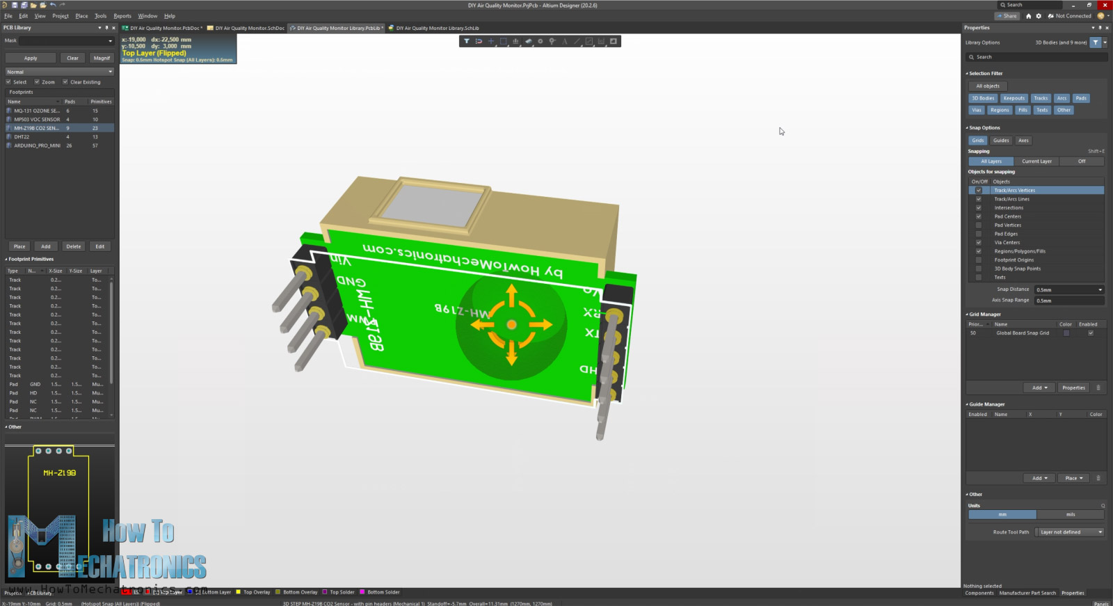
You can also create your own components libraries. I created most of the components for this project on my own, as I wanted to create my own 3D footprints for each part so that at the end, I would get the whole PCB in 3D. For creating 3D models for the PCB footprints, you can use any CAD software, save the files as .STEP files and import them in Altium Designer.
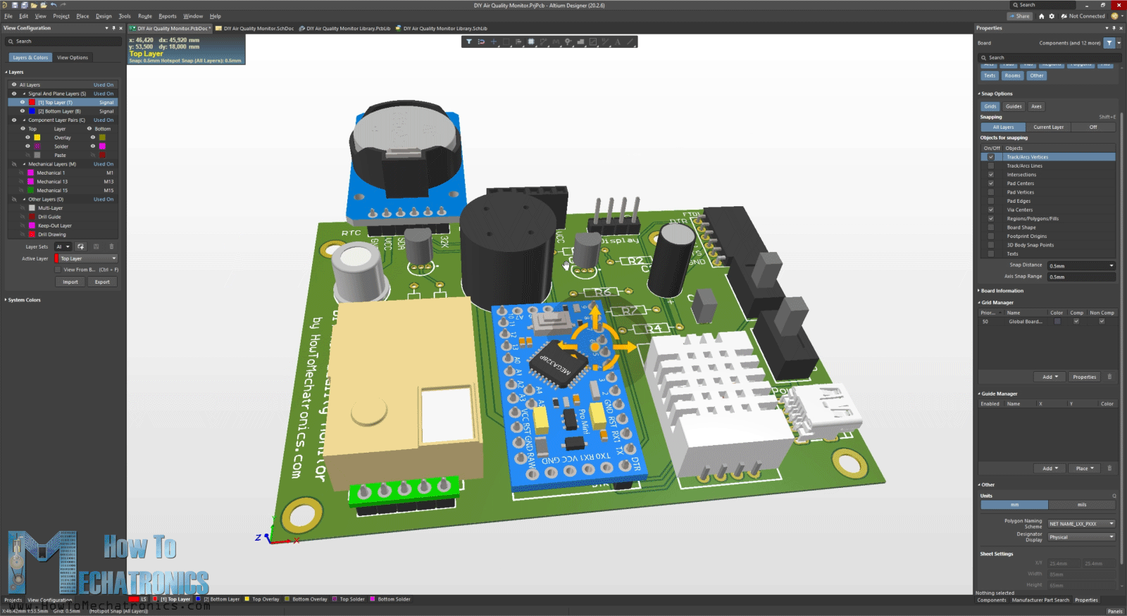
Once I finished the schematic, I generated the PCB. I arranged the components as I wanted, and with just a simple click using the Auto Route feature, the software generated all traces automatically.
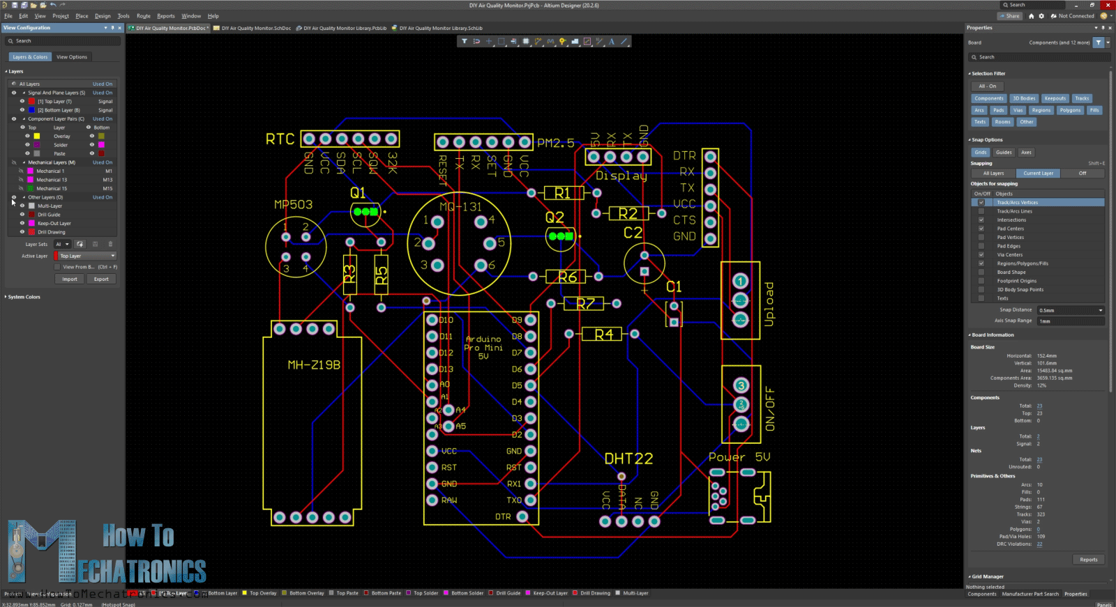
If needed, we can manually create or adjust them. Also, we can set design rules how the auto routing will make the traces, set different widths for each net and so on. At this point we also see the PCB in 3D and export a 3D file of the entire PCB assembly which will be used for designing a case for it later on.
Nevertheless, I would like to thanks Altium for sponsoring educational content like this. If you would like to find out more about this software and also try it out, you can check out the links below. You can also try the web based Altium 365 viewer for project previews and file.
Altium Designer free trial – https://www.altium.com/yt/howtomechatronics
Altium 365 viewer: https://www.altium.com/viewer
Here are the Altium Designer project files:
Altium Designer files including the project file, libraries and .STEP files of the 3D models of the electronics components:
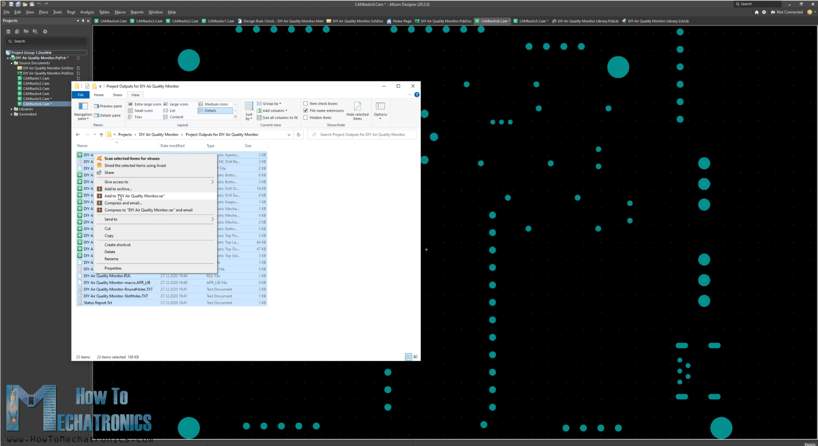
PCB Gerber file:
Ok, so once I finished the PCB, I generated the Gerber and the NC Drill files, put them into a single zip file, and so I was ready to order the PCB to be manufactured.
I ordered the PCB from JCLPCB. Here we can simply drag and drop the zip file and once uploaded we will get all visual information about our PCB.
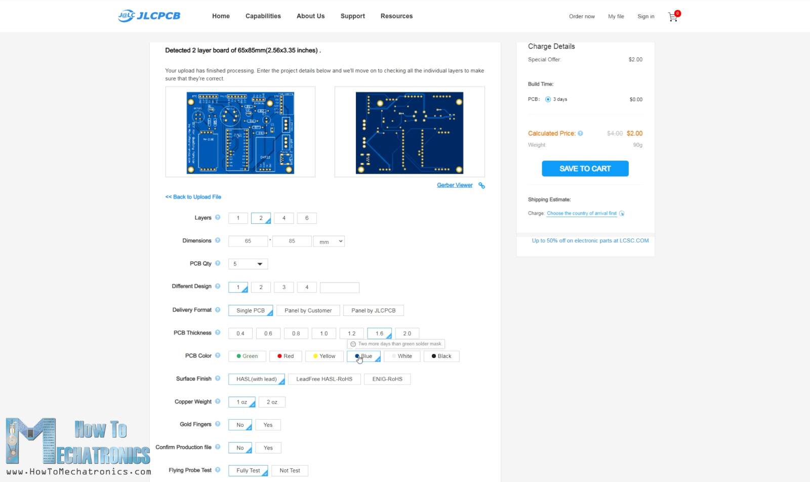
Then we can select the properties that we want and order our PCB at a reasonable price.
Assembling the PCB
After several days the PCBs have arrived. The quality of the PCB is great and everything is exactly the same as in the design.
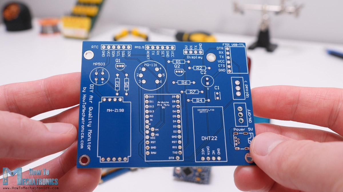
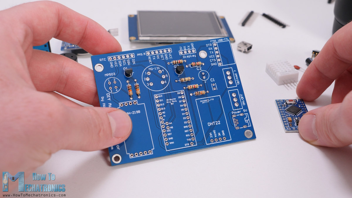
So, now we are ready to start assembling the PCB. I started by inserting and soldering the smaller components first, the resistors and the two transistors.
Then we can solder the Arduino Pro Mini board in place. However, first we need to solder the pin headers to it. Please note that we don’t need all its pins, but make sure you don’t miss the one we need like the A4, A5 and the DTR pin. Also make sure you have this exact same Arduino Pro Mini board with this layout of pins, because they can sometimes be different.
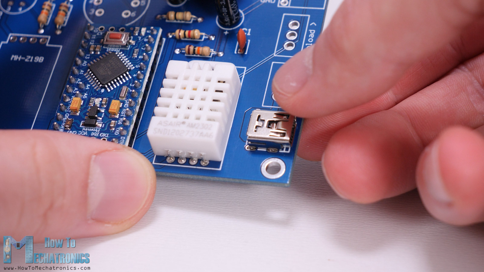
Next, we can insert the DHT22 sensor in place. For that purpose, first we need to bend its pins 90 degrees. Sometimes I also use Blu-tack adhesive for keeping the components in place when soldering.
The two capacitors used in this project are for stabilizing the power supply. The power to the board will come from a mini-USB connector to which we can connect 5V.
Right above the power supply connector we need to solder the two switches. One is for turning on and off the device, and the other is used when we want to upload a sketch to the Arduino board. Then we can insert the pin headers for the USB to UART interface, the display and the PM2.5 sensor, as well as the VOC, the Ozone and the CO2 sensors in place.
Next, for soldering the DS3231 Real Time Clock module again, first we need to bend the pins 90 degrees. Once soldered we can insert the battery which keeps track of the time even when main PCB loses power. With this the PCB is actually done, and what’s left to do now is to prepare the cables that we will use for connecting the PM2.5 sensor and the display to the PCB. I soldered male pin headers to the cable that comes with the sensor, and so I was able to easily connect it to the PCB. For connecting the display to the PCB, I soldered four wires to the back side of the display connector and then connected them to the PCB.
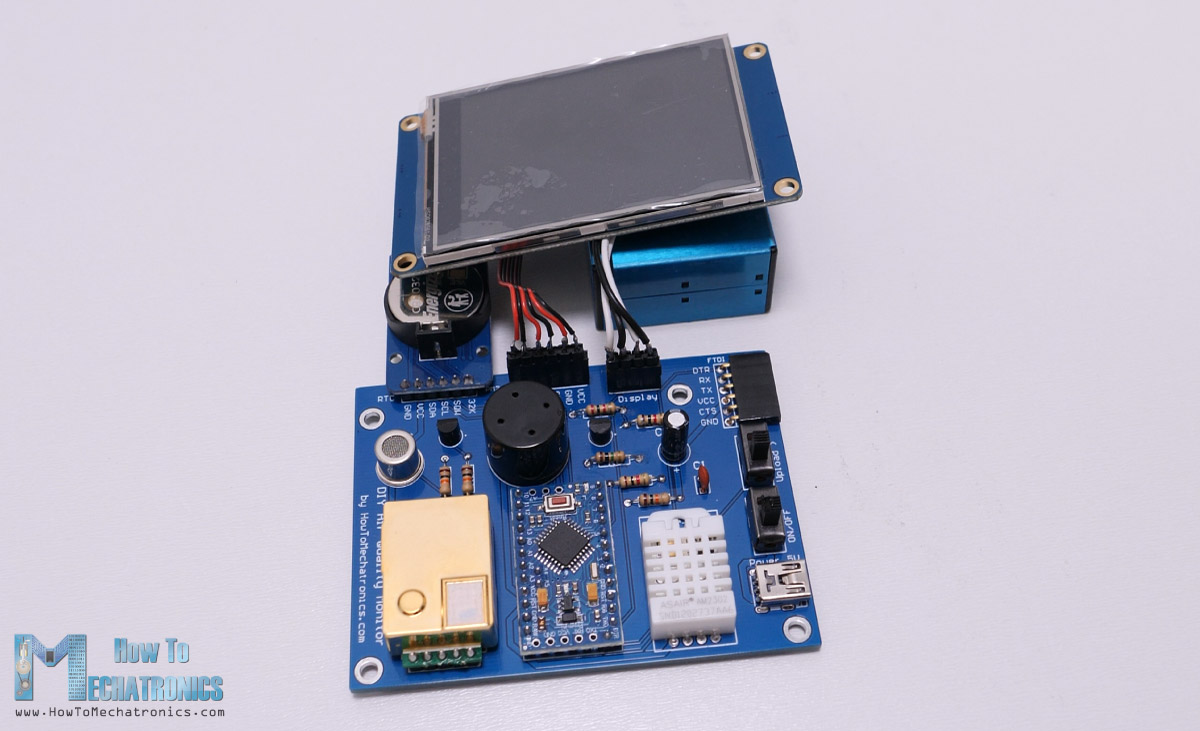
And that’s it, our Air Quality Monitor is actually done. Of course, what we need to do now is to make some kind of box or case for it. As we have the 3D model of the entire PCB assembly from Altium Designer, we can import it in a CAD software and design a case for it.
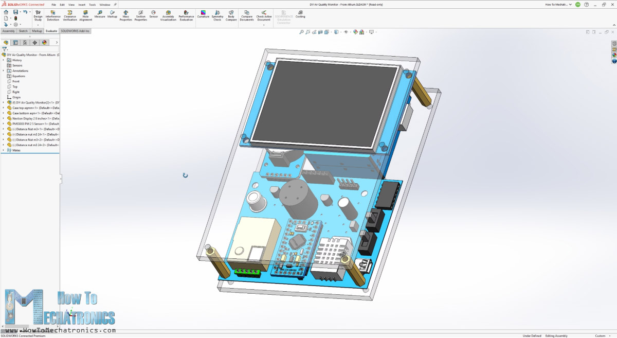
I used SOLIDWORKS for that purpose, and made the simplest case possible consisting of just two parts and few bolts and nuts. I decided to make the case using transparent acrylic because I like how the PCB and the components look exposed and it’s also a great way to show off your DIY project.
You can download this DYI Air Quality Monitor 3D model, as well as explore it in your browser on Thangs.
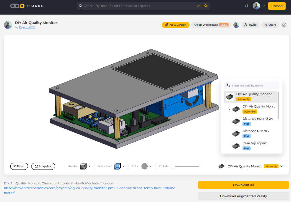
Download the 3D model at Thangs.
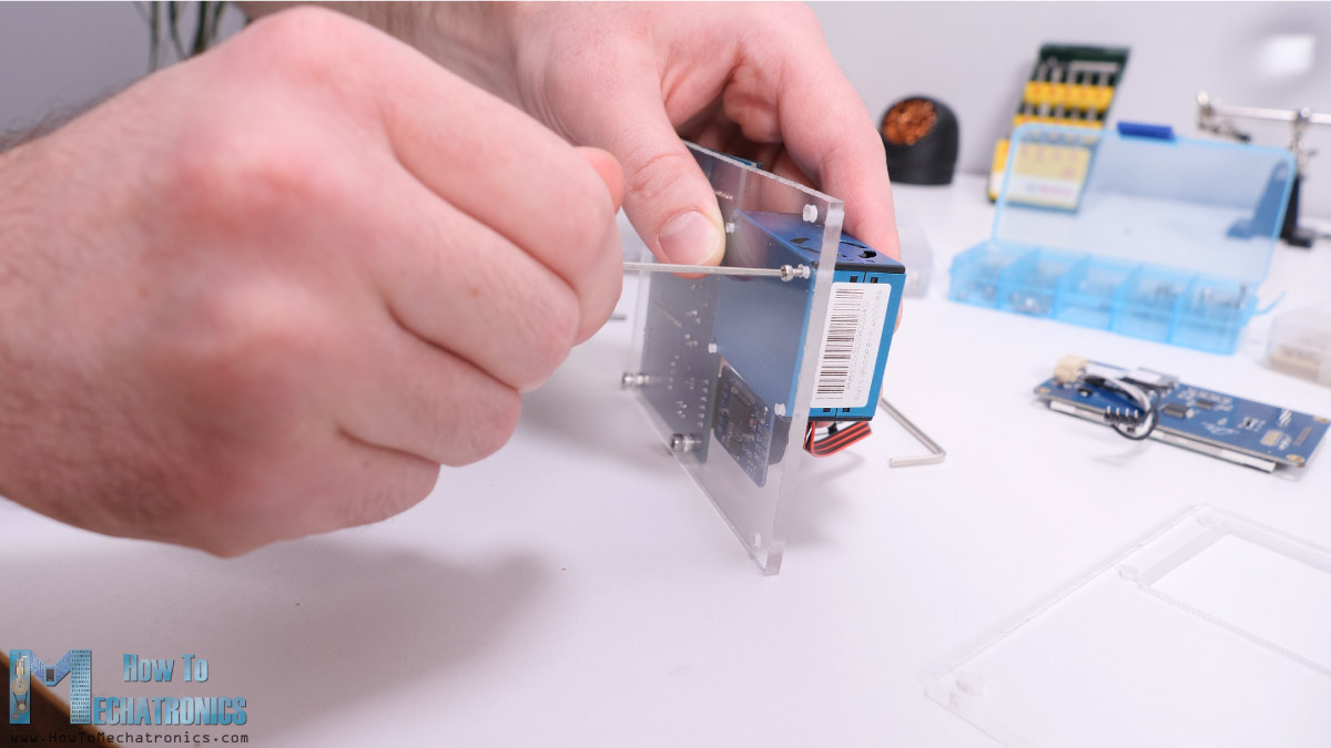
Making the Case for the Air Quality Monitor
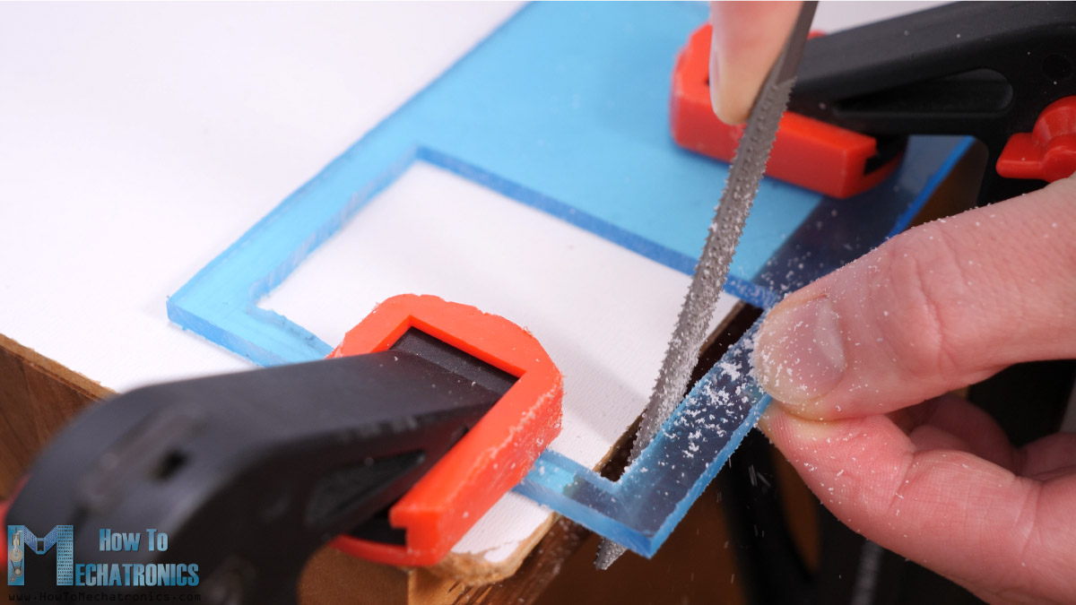
The acrylic that I will use is 4mm tick which perfectly fit with the display. As I currently don’t have a CNC machine, I cut the shapes manually using a simple metal hacksaw.
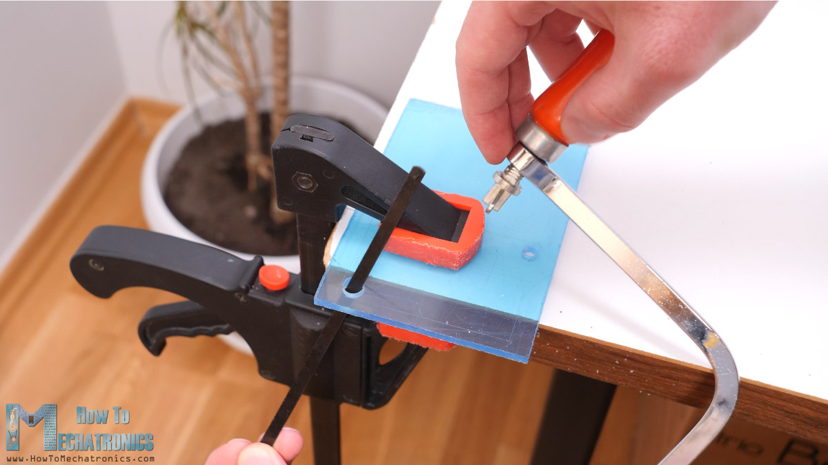
For making the opening for display, first I made two holes with a drill. Then I passed through a blade from a mini hacksaw and carefully cut the shape. Using a simple rasp, I smoothed out shape. Then using a 3mm drill I made all the holes for attaching the PCBs and connecting the two acrylic plates together.
At this point, I removed the protective foil from the acrylic which, and to be honest, that’s quite satisfying process. For attaching the PCB to the base plate, I used some M3 bolts and nuts. For attaching the PM2.5 sensor to the plate we need M2 bolts.
Next, using some distance nuts we can join the two plates together. By using one female and one male distance nut I was able to easily get the desired distance between the two plates.
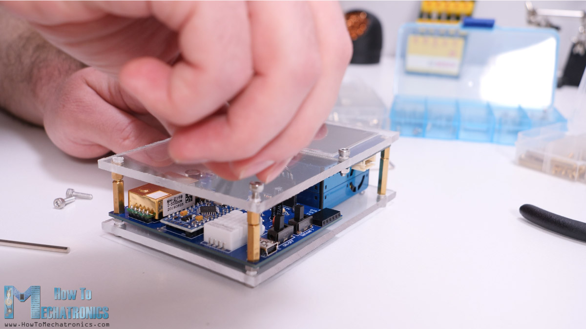
I personally really like how this case turned out, plus, it’s functional as air can easily circulate around the sensors.
Programming
All right, so now we can power up the device and upload the program. We can power the air quality monitor through the Mini USB connector and we can get the 5 volts from a 5V USB adapter, a 5V phone charger or a power bank.
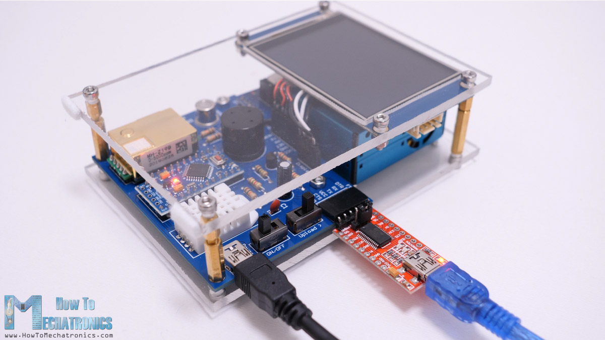
For uploading the program to the Arduino Pro Mini board, we need an USB to serial UART interface which can be connected to the programming header. Before connecting it to the computer USB, first we must turn on main power of the device, because otherwise the power coming from the computer USB which is only 500mA might not be enough to work properly. When uploading the Arduino sketch, we also need to switch the upload switch on the PCB.
Here you can download the Arduino Code and the Nextion Display Program:
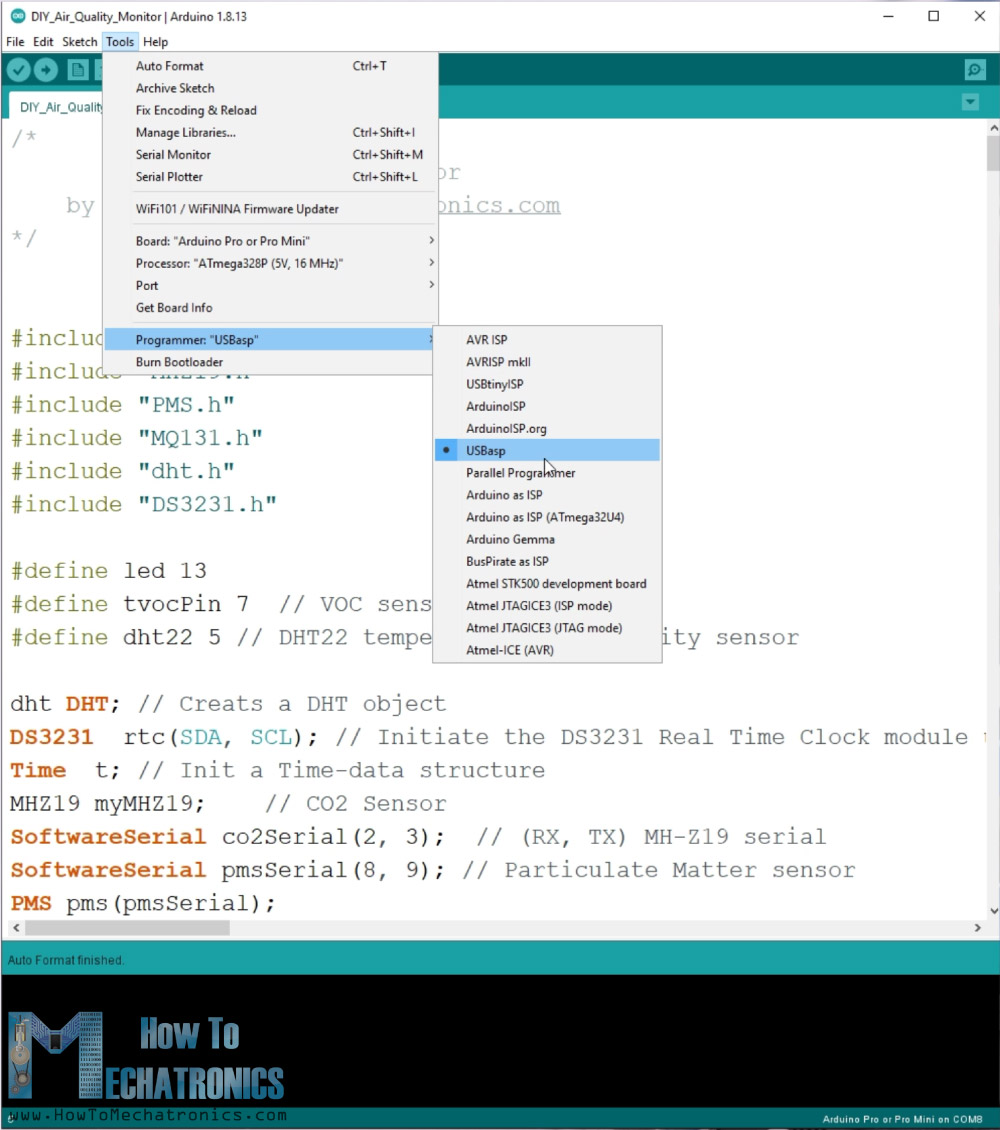
For uploading a sketch to an Arduino Pro Mini board, in the Arduino IDE first we need to select this board, select the proper version of the processor, select the port and select the programming method to “USBasp”.
Once we upload the code to the Arduino, we also need to upload a code to the Nextion display. Nextion displays have built-in ARM controller which actually controls the display on its own.
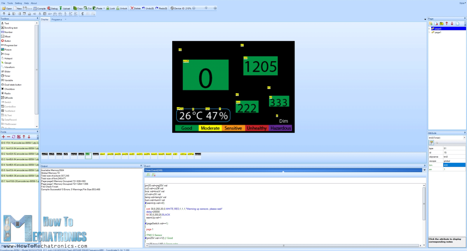
All graphics like buttons, text, images, variables and so on, are generated and controlled by the display itself. The Nextion display has a dedicated Nextion editor where we can create all these stuffs. The display and the Arduino communication with just two wires using the serial communication. The Arduino simply just sends the values from the sensor to the display and vice versa, the display sends data to the Arduino when needed.
For uploading the display program, we need a microSD card where we can save the output .TFT file from the Nextion editor.
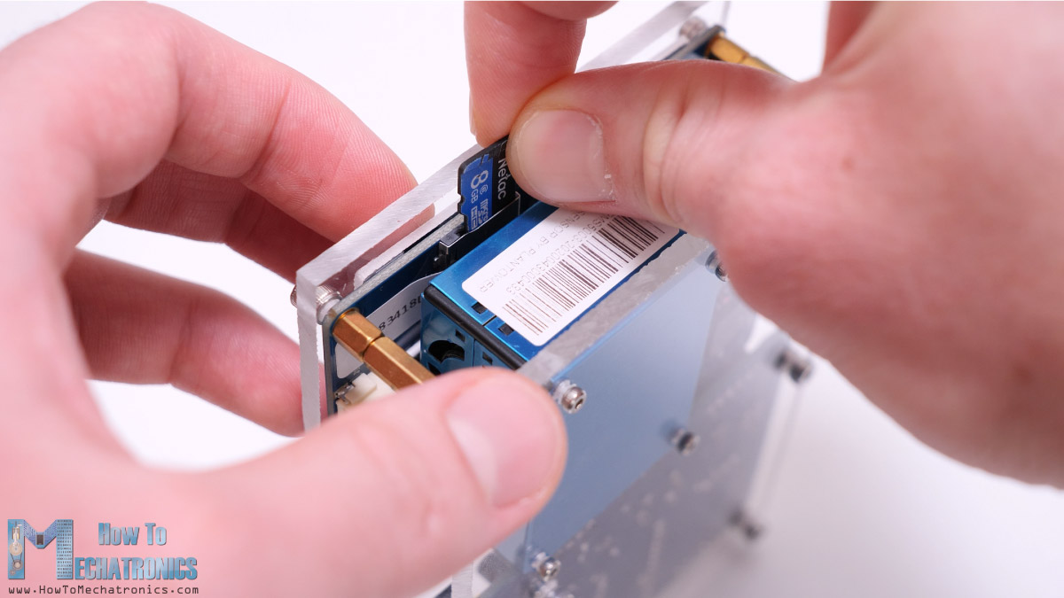
The display has a card reader where we can insert the microSD card while the power is off. Then we can power up the device and the program will be uploaded to the display. Now we just have to remove the card, switch on the power again, and our air quality monitor will start working.
Code explanation
So, we are using libraries for each sensor and which can be found on the following links, MHZ19, PMS, MQ131, DHT, DS3231. In order to better understand how we read the data from each sensor I recommend reading the libraries documentations and try out their examples.
We are also using the SoftwareSerial library because both the MH-Z19 and the PMS5003 sensors use the serial communication. The Arduino and the Nextion display also use the serial port for communication and in this case we are using the default, hardware serial.
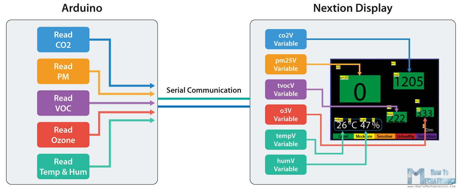
So, the Arduino reads the sensors and sends that data to the Nextion display. Here’s an example.
Serial.print("tempV.val=");
Serial.print(temp);
Serial.write(0xff);
Serial.write(0xff);
Serial.write(0xff);Code language: PHP (php)
So we have a variable at the nextion display called “tempV” and in order to update it’s value we need to send a command to the nextion as following “tempV.val=22”. So the variable name, then “.val”, then the value, let’s say 22. The first two lines of the code do that, and in order the Nextion display to accept this command or actually any command we need to send the three unique “write” commands.
In the Nextion display program, we have a timer which runs in a loop, just like the Arduino code loop, and it constantly updates the numbers on the display.
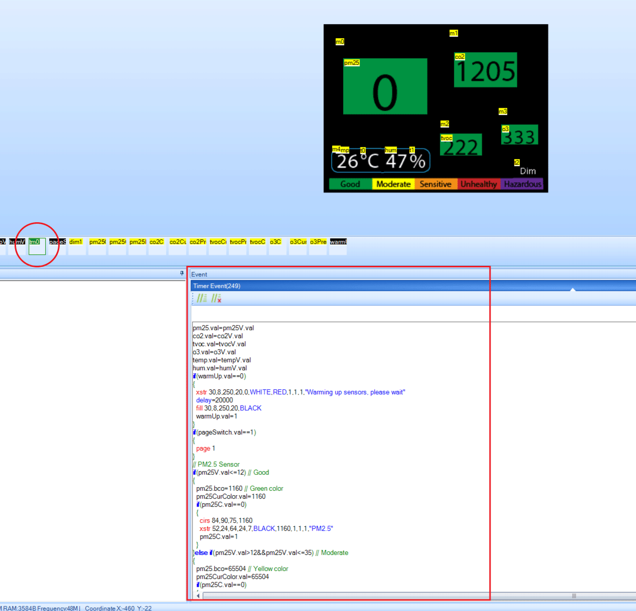
In this timer event we also have a code for changing the background color for each sensor depending on its value.
On the second page we have waveform, which gets the values from the stored values from the Arduino. Please note that you can find more info on the Arduino code itself as there is explanation in the comments of the code.
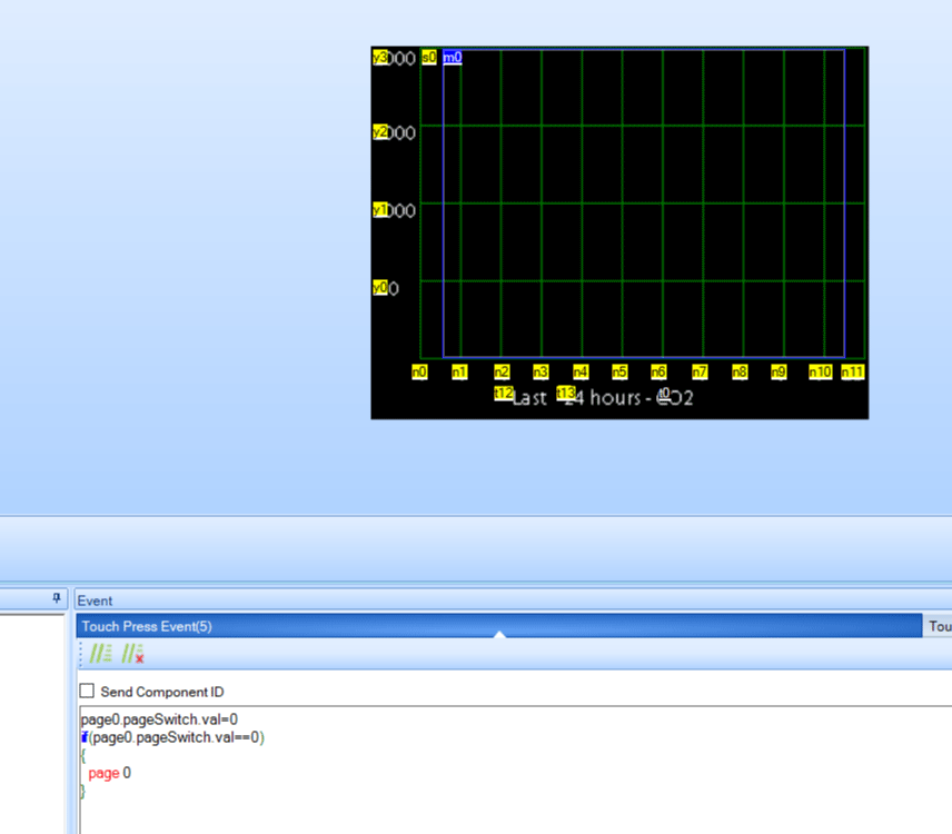
The hours and the Y-axis values also get their values from the Arduino.
On top of the waveform, as well as the numbers on the main screen, you can notice we have like transparent objects, called “Hotstops” in the Nextion editor, and they are act as buttons. If we press the hotstop on the waveform we can see in the Event section that it sends us back to “page 0”.
Overall, that’s how the program of this Arduino air quality monitor works. Of course, in order to fully understand how it works you need to learn and know how each sensor works with their libraries, as well as how the Nextion display works.
Please note that for the VOC sensor we are only reading raw data from this sensor, not ppm or ppb values. Just analog values from 0 to 1024. Higher values means there is a presence of VOC.
As for the Ozone sensor, in order to get more accurate outputs we must set the setTimeToRead() and setR0() values correctly according to the calibration example of the library. However, longer setTimeToRead means the program will be blocked while sampling and everything else will be freezed. Of course, there are ways to work this around. I would even suggest not using the ozone sensor at all unless you really need it.
I hope you enjoyed this video and learned something new. If you did please consider supporting me on Patreon. Feel free to ask any question in the comments section below and check my Arduino Projects Collection.
Hi Dejan,
Thanks for this nice project and the great files,
Can you confirm the correct resistors values for all of them ( there are so many comments regarding resistors, and each one is different, and since I’m new to Arduino, I got lost)?
I connected them as follows:
R1=2K
R2=1K
R3=10K
R4=10K
R5=1K
R6=100K
67=1K
Are those the right values??
The mini Arduino isn’t working! (IDE can’t recognize the port no matter how hard I have tried). I’m afraid that I have used the wrong values.
So either my Arduino is broken, or resistor values are wrong.
Please help!!
Hi, the values are correct, but not sure whether R1 should 1k and R2 2k. As for Arduino not being recognized, it happens sometimes. Make sure you have the Upload switch turned so that the RX and TX pins are disconnected when trying to connect the Arduino.
Two questions, same subject, the two-round sensors how do you pick orientation? I ordered the parts a few weeks back and some are here so I thought I could put some of it together. Right away I don’t see any markings for pins or even pin 1 on the mq-131 and how about the mp503? How about the PM2.5 wiring, I have 8 wires yet only 6 are on the board? Did I buy the wrong one?
Yeah, the orientation for those sensors is a bit tricky to identify. The MP503 has a small notch which should be pointing up. And as for the MQ-131, it can be set in any direction, as the pins 1 and 3 and 4 and 6 are connected to each other, basically the same connection.
The cable coming with the PM2.5 sensor has 8 wires, but you need only 6 wires. Use the same connector as it is for the sensor side, and on the other side get rid of two wires, and solder a pin header or anything so you can connect it to the board.
Thank you, Dejan! Soldering it all up now!
Hi Dejan,
Thanks for the project. The ciruict board really simplifies the assembly and makes for a nice package.
I would like to change the temp display from deg C to deg F. I can update the arduino code without problem, but I’m having trouble figuring out how to change the “C” to an “F” in the Nextion editor. I can’t find where the “C” is actually defined. Can you provide some insight into this change?
Also, to get the arduino to load properly, I had to change the processor settings to the 8 Mhz version of the ATmega 328. (Maybe it was the cheap part I bought!)
Finally, running the ozone calibration code included with the library and changing RO in the arduino code really stabilized the readings. (My reading was substantially different from RO in the code.)
Thanks again.
Hey, glad to hear it, thanks!
Well the “C” is just a “Text”, t0-variable and you can change the “C” to “F” in its attribute tab “txt” value (bottom right corner of the Nextion editor).
With the students of a secondary school, we built 8 different indoor air monitors as a project. Yours was the most attractive for the students because of its concept and especially its touch screen.We compared them for more than a week side by side with a calibrated master (TSI IAQ Q-Trak 7585). The Chinese sensors (MHZ-19, PMS5003, DHT22) in your build are cheap, present a measured value anyway, but are easily outclassed by slightly more expensive Sensirion (SHT3x, SPS30) and Senseair S8 sensors of European make. Only the latter have found their way into classrooms in the fight against Covid-19 because they proved to be sufficiently reliable.
Nevertheless, the students were most interested in your design, which could perhaps be updated with better sensors. It was an instructive and interesting building project.
Regards
Hey, I’m glad to hear this, thanks for the input!
Hi, this is a great project, and I am really happy that someone took the time and dedication to do this. I am a public health student working in remotes areas of the country. My question for you is, is there any way the data could be logged on an sd card that could be installed on the PCB instead of using a screen?
Hey, thanks! Sure it’s possible. You would need a SD card module for that purpose and modify the code accordingly. If you have experience with Arduino it should not be that hard to implement it, but still there are quite some modifications to be done.
Hi
I have built one based on what you have given. Everything works at this movement, except the 24 hrs plot. When I press any parameter, it says Please wait, stay in this main screen for ever. Do I have to run the unit for 24 hours non-stop prior to press the plot option.
Regards
Raj
Hey, make sure the “Upload” switched on down or off, and yeah, sometimes when you click it doesn’t enter the plot. The delay to enter is about 10 seconds, if it doesn’t enter try again. 🙂
Dear Dejan,
on more time: thanks for this nice project and the great files and everything, so it can be rebuilt.
As my Ozon-Sensor does not give any values at all, and a friend of mine got the exact same parts from me and built it as well: he gets values, even thogh he claims, that the values are a bit confusing and that there is too much dynamic in the values… I would like you to confirm the following:
R1 2k
R2 1k
R3 10k
R4 10k
R5 1k
R6 100k
R7 1k
What do you think: I had mixed up R6 and R7…did I grill my Ozon-Sensor?
I have checked the geating supply and that seems to work ok as the input on the transistor is also reflected on the output of those.
One more question to the Ozon-Sensor: is it correct, that it can be place in 2 ways on the PCB? Does the oriantation matter? From the specs I think it should be ok…but I am just 70% sure, just wanted to get your OK…
Thanks so much for the project again, as it gave my friend and me a great step into this metering at all, and also into the way how this can be done with cheap ready-to-use-components, which are so easy to be connected to a “brain” like you did. I also thought of an additional value, that can be given for AIR: Pressure! So the BME280 could be a good implementation, agree?
Hi there and thanks! Well I’ve mentioned at the end of the articles that the Ozone sensor might not work properly, because of the code. The code is not well optimize and not properly set to get accurate values from the Ozone sensor. I should have mentioned that in the video as well so people don’t get confused. You can check and only the example from the Ozone library, in order to get true and real values from the sensor. The library also has a details how it work on Github, https://github.com/ostaquet/Arduino-MQ131-driver.
The problem is that the library uses delays when reading the values from the Ozone sensor, and in order to get accurate results those delays are long like 50 or even 200 seconds ( you get these values with the Caliabration example from the library files). So we use smaller values like 5 to 10 seconds and that’s why we don’t get accurate results, but we have to use smaller values otherwise everything else will be frizzed for example for 200 seconds. If you don’t mind that, you can actually set the in the setup section with the “setTimeToRead(value)” function. Also you need to adjust the “setR0(value)” according the the Calibration example.
I have rebuild this project and it is great fun to do so, as everything has a great description and all downloadable files ghelped and worked fine.
Thanks for thie great project: so much fun!!
WiFi-connectivity would be a great benefit!
I will try with ESP-01…
One issue is still left: I do not get any values for Ozon?!?!
It is always 0. The sensor has no direction to build in, correct? There is no direction mark or anything else…. please confirm!
Hey, nice to hear you built it! Well yeah, the Ozone sensor reading is a bit complicated as it uses blocking (delay) function inside the library. Try to use the library example to test just the ozone sensor. In such I think you will get proper values. The code that I proved it doesn’t work the best for the Ozone sensor, that’s true.
hello have you seen my arduino nano version ?
https://www.youtube.com/watch?v=X929zjn_TPA&t=1s
thanks for sharing your project i do the mecanum robot too. But the code is a little slow when you want add some stuff.
Glad to see you build it! It looks great with that case.
Hi Dejan,
This evening, I finished the plastic enclosure of the system and everything is working perfectly! I’ve followed exactly your instructions and it works perfectly.
A huge thanks and I’m waiting for the next project ;-).
Hey, I’m glad to hear it! Cheers!
Really great project. With Wifi or BT and additionally barometric sensor for pressure it would be the killer station.
Regarding Altium Designer, looks really great however price tag is out of this world for hobbyist, unfortunately.
Hi Dejan,
LOVE this project!
I have followed your guidance and have made several of these as gifts already. I would LOVE to see a version #2 of this project with Wifi or NRF24L01 to publish MQTT data to my local broker.
I now follow you on all medias now,
Thank Again!
Hi Dejan,
this is a great project – thanks for the details you shared here.
I noticed that you mixed up the resistor values (for the analog inputs/transistors) between all your schematics
– in the first symbolic overview you used 1M resistors for the analog sensing (VOC and Ozone)
– in the Altium schematic snapshot you used a 10k sensing resistor for the VOC sensor, while the resistors R6/R7 seem to be interchanged (but still that would be 100k for the sensing resistor); also the voltage divider R1/R2 has to be vice versa in order to get 3.3V from the Arduino 5V
– in the attached schematic files, the voltage divider R1/R2 is correct, but the resistors R6/R7 are still interchanged (and now back up to 1M)
As far as is understand the datasheets
– the current limiting resistors R5/R7 for the transistors Q1/Q2 should be 1k
– the sensing resistor for the VOC-sensor according to the library on github is 1M (but the 100k seem more appropriate for the 1k-30k sensor resistance)
– the sensing resistor for the Ozone-sensor should be 10k
Can you check that with your experience?
Well, that’s actually true, the resistors values are a bit messed up across the schematics, sorry about that. However you did figure them out quite well, and your points are correct. Thanks for the input!
for the benefit of your reader, I suggest you list out the resistor value and also update your schematics.
Thanks
Yep, right, I added a note right next to the schematics with the correct values.
Hello Dejan,
Very interesting Project, however, standalone is a bit limiting.
Have you considered swapping the ProMini for an ESP 8266? or maybe even an ESP32? That would make integrating it into a current System, be it homeassistant or other, very easy!
Thank you for your time o/
Hi Dejan,
nice project. It captivaded me right away and I wanted to give it a try and build it. The thing is, I´m quite new and inexperienced with electronics and I have some questions.
What kind of capasitors are needed? I can read the value of the resistors and transistors but not of the capasitors.
I´m in the procces of gathering all the needed parts and would come back to you, if I have some other questions, if you´re ok with it.
Best regards and thank you for this very usefull and intresting project,
Christian
Hey, glad to hear it, thanks! I updated the article in the parts list section, please check it out now. I hope you will have fun building one. As for the electronics, I think you should be fine as if you connect everything as explained everything will be fine. On the other hand, keep it in mind that it can be a bit hard to understand how everything works, especially the programing part, as to be honest it’s actually not that well optimized. Cheers!
Dejan,
Great project. But your download links do not seem to be working. Specifically the Arduino code, the Solidworks file and the Altium Designer files. All I get with each of them is a 4k invalid .RAR file. Your help would be appreciated as I have just finished ordering all the parts and sensors for my build.
Regards..Ian
Hey, thanks! Try to use different web browser to download the files. I’ve just checked and they work fine.
Hi Dejan!
Awesome project, thank you!
Could you help me understand why you used two transistors in the project? How do they activate the sensor heater?
Why out of the RX signal of the PMS5003 PM Sensor there are two resistors, 1K and 2K, but the RX seems to pass only out of the 1K resistor, is it the 2K a pull-down resistor?
Thank you for your help!
Hey, thanks! The resistors for activating the heaters of the two sensors (connected to the base of the transistors) are used for limiting the transistor base current. On the other hand, the two resistors at the PMS5003 Sensor are used as voltage divider. The PM sensor RX pin operate at 3.3V, so with the two resistors we make a voltage divider which drops the 5V coming from the Arduino to 3.3V.
Hi Dejan,
Great project. I have everything on order except the passive components. I cannot locate a complete bill of materials on this project page. Capacitor values, resistors, transistors, header pins, switches and usb connector. Can you please point me to the complete BOM?
Thanks! Cant wait to assemble and start using this!
Hey, thanks! I have updated the article in the parts list section, please take a look now.
Hi,
Nice project.
The Amazon link for the arduino pro mini is different.
The banggood version looks correct.
Hey, thanks! Well yeah, that one is a bit different, but you can still use it as the pins that we need and use in this project are all on the same place.
Nice project. Ever thought of changing the arduino pro mini to maybe an ESP32?
Then you could ditch the rtc, the switches and usb connector. It would also probably be faster at refreshing the data and also have wifi (so ntp time and you could upload data somewhere).
Hi Dejan,
I like this project so much even from the Arduino robot arm with smart phone control
this is my second project or third I think. Can we use NRF24L01 module make it send massage when are away. By the way I’m 13 years old it can crazy. I wish you will answer soonly.With my greeting kirubel.
Hey, glad you like it. Well sure you can make any modification, you can use NRF24L01 for wireless transmitting of data.
There is a wire missing on the schematic diagram shown above. There should be a connection from pin 6 on the MQ-131 to the A0 input of the Arduino.
Well they are indicated with D6 and A0 in the diagram. I didn’t draw all the lines because it would have been a mess and harder to see things.
Thank you so much for this article! – It was exactly something I was considering to make in the near future. Few days ago I made a copy of your cnc foam cutter – looking forward to making this project as well!
Nice to hear that, thanks!
Hi Dejan,
nice that you publish a project again, I always wait with excitement for the next projects, I will definitely build your completely new project,
Please stay healthy
Greetings Wolfgang Rupp from Germany
Hey,
Glad to hear it, thank you!
Stay healthy too, cheers!
Can this air quality monitor send data to mobile app through wireless network?
This would be amazing upgrade! Hope that he makes it and add instructions here as well.
You could if you replace the Arduino with an ESP8266 or ESP32 device. They are Arduino compatible and have built in WiFi. Not sure about the pinouts off the top of my head though.
This project is so cool! Any chance for an additional integration with Home Assistant? 🙂
This project no.
you can try with esp8266 and arduino framework on it.
I think with a little work, you can do it.
Well we would have to add a wireless module to it. In the current configuration that’s not possible.