In this project we will learn how to make an Arduino based DIY vending machine. I will show you the entire process of build it, starting from cutting and assembling the MDF boards, to connecting all electronic parts together and writing the Arduino code.
You can watch the following video or read the written tutorial below.
Overview
The vending machine features four discharging units controlled via four continuous rotation servo motors, a carrier system controlled via stepper motors, an LCD, four buttons for selecting an item and a coin detector.

You might be thinking now that the item carrier is not so useful for this vending machine, and yes, you are probably right. But my idea here was to make this project more interesting or a bit more complex so you can learn more new stuff. I think this project idea can be great for electronics or mechatronics students considering building one as their final year project, as well as for any Arduino enthusiasts.
Building the vending machine
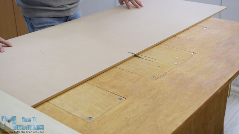
I started by cutting the 8 mm tick MDF board to size.
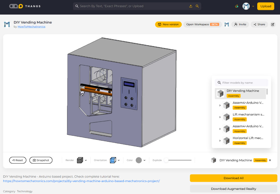
I previously made a 3D model of the machine from where I got all measurements.
You can find and download this 3D model, as well as explore it in your browser on Thangs.
For cutting the MDF I used a circular saw. Actually this is a homemade workbench featuring a circular saw, a router and a jigsaw, made by my partner Marija and there is a DIY video for it on her YouTube channel Creativity Hero.
After cutting all panels using the circular saw I continued with making the openings in some of the panels using the inverted jigsaw.
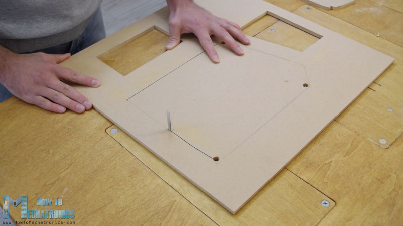
Actually a jigsaw can be even used for the previous step in case you don’t have a circular saw. I also used the Jigsaw for cutting the smaller parts which had several cuts. However, note that these are dangerous machines so you need to be very careful when using them.
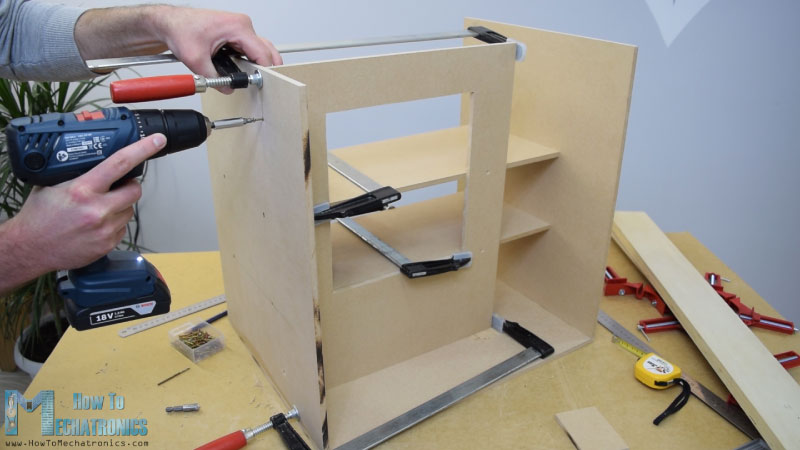
Once I had all MDF parts ready, I started assembling them using some wood glue and screws. For fastening the panels I used 90 degrees angle clamps. Using a cordless drill I first made pilot holes, then made counter sinks and screwed the 3 mm screws in place. I used the same method for assembling all panels and for some of them I also used some F clamps.
Rail system
At this point of the assembly I will continue with making the rail system. For that purpose I’m using aluminum tubes which I cut them to size using a metal hand saw. The diameter of the tube for the horizontal rail is 16 mm, while for the vertical rail the diameter is 20 mm. On a solid 18 mm wood boards I made slots for the tubes using Forstner bit and then attached the tubes to them.
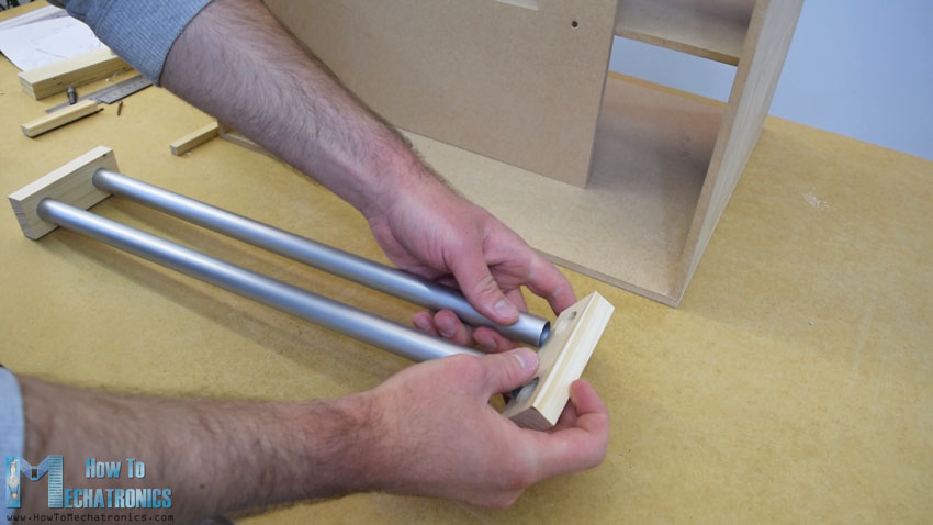
The horizontal rail is made out of two 27 cm long tubes, while the vertical rail is made out of three 45 cm long tubes.
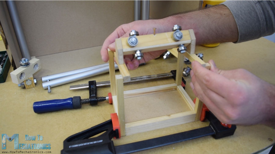
Next are the sliders and here’s how I made them. I used 21 by 21 cm wood board on which I made 8 mm holes.
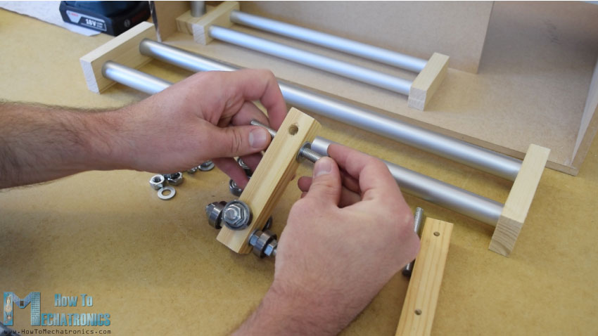
Then I inserted 8 mm threaded rods through these holes and using washers and nuts I secured the 22 mm bearings. As for the horizontal slider, I used the same method but with smaller bearings of 16 mm in outer diameter.
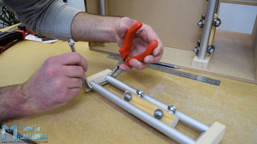
After I inserted the slider in between the tube rails I noticed that it was a bit loose. For solving this problem I had to reduce the distance between the two rails. So first I expanded the tube slots, then made perpendicular slots through the tubes, and finally using a threaded rod fastened the two tube rails closer to each other. After this the sliders were no longer loose and they worked properly.
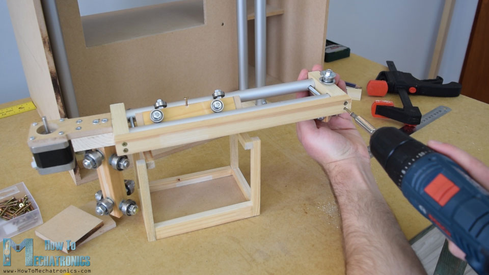
However, at this point I had to disassemble the rails in order to add the other elements to it. First I added a 5mm bolt on the left side of the rails on which I will attach a pulley for the horizontal timing belt, as well as two more bearings which will slide on the left vertical rail.
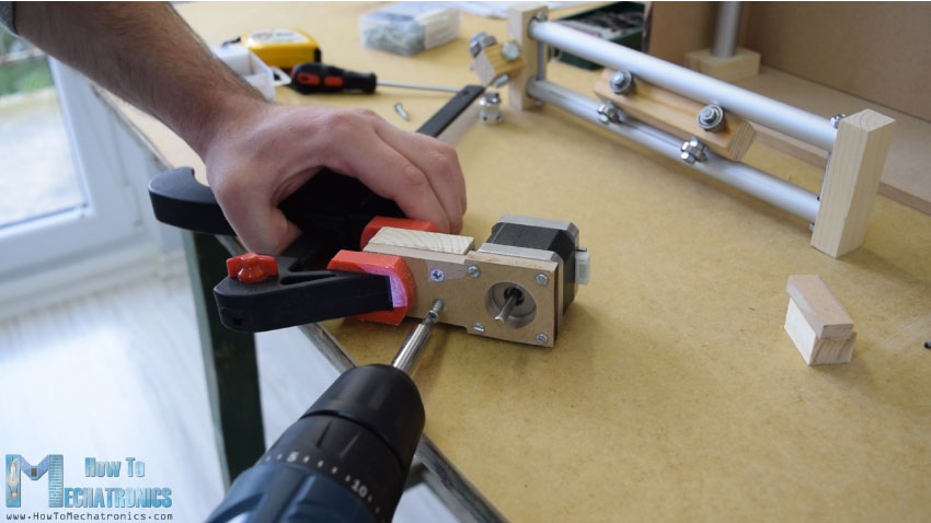
On the other right side of the rail I had to attach the stepper motor for the horizontal movement. First I fastened the motor on an 8 mm MDF board, then added a supporting piece of wood to it, and also secured the slotted part to it. Finally I attached this whole assembly onto the vertical slider using a wood glue and two screws.
Next, I continued with adding the container on the horizontal slider. For that purpose I used some small pieces of wood which I joint them together using a wood glue. Once I was done with this I was ready to assemble the rail system. I used some epoxy in the rail slots and added an additional wood board to the side of the rails to make the whole rail system stiffer.
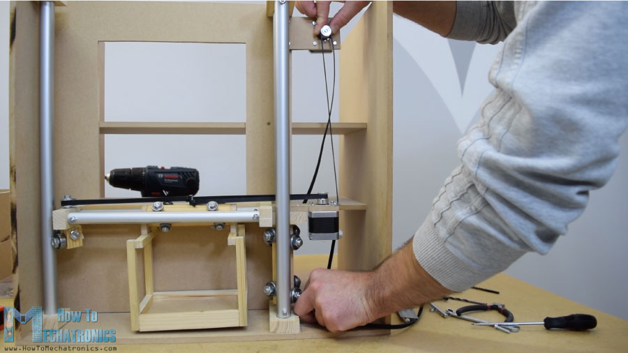
In the next step, I inserted the assembly in between the vertical rails and secured them in place as well. The final result of the sliders and the rails system turned out working excellent.
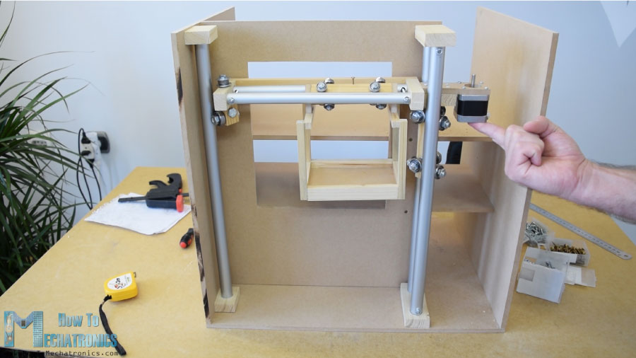
I continued with installing the horizontal timing belt. I measured the length I needed, cut it to size, and secured it to the slider using a zip tie. As for the vertical slider, I attached the stepper motor on the top of the machine using a piece of MDF and some bolts. At the bottom, I attached the pulley and in a similar way installed the timing belt.
Discharge units
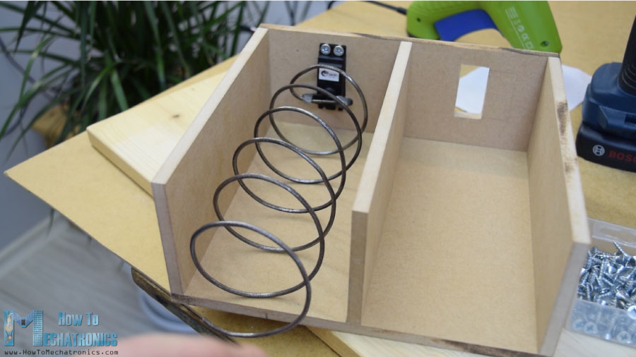
Next, I moved on to the item discharging unit. I made a helical coil out of 3 mm tick metal wire by wrapping it around a 7cm in diameter spray paint can.
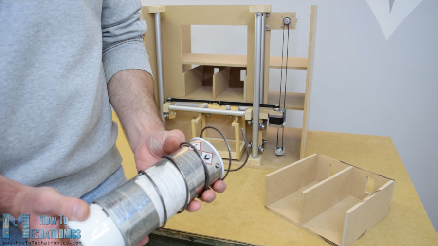
After that using a glue gun I secured it to a continuous rotation servo motor.
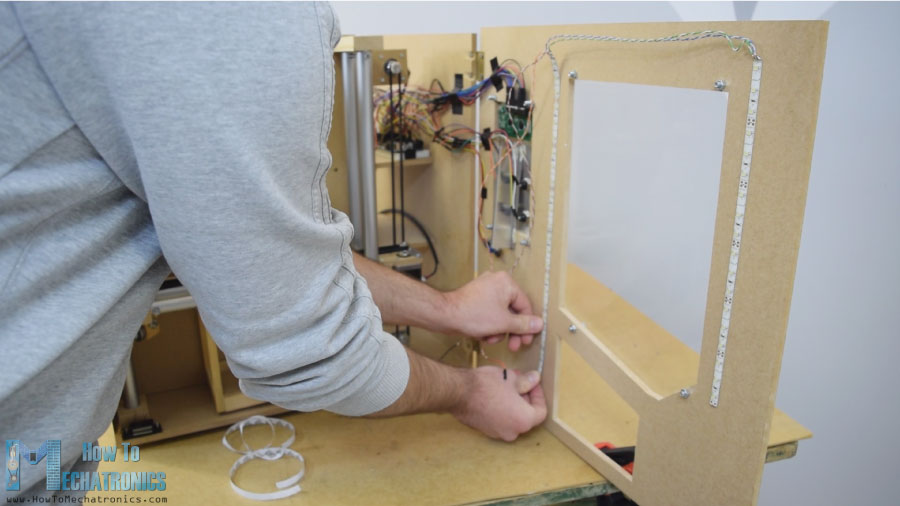
Front panel
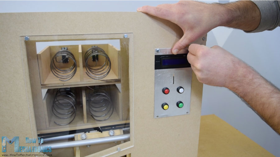
Next is the front door panel which I attached to the vending machine using simple hinges, and for locking it I used a magnetic door catcher. Then I used a 5mm tick acrylic to cover the big front opening, while for the smaller opening on the right side I used a very tin aluminum plate. Here I made 4 holes for the buttons, as well as openings for the coins and the LCD display. I used a drill and a hack saw for making them. Once I attached the electronics parts to the aluminum plate, I attached then to the front door panel using 5 mm bolts.
For positioning the carrier to its starting position I installed two micro switches and for the coins I glued a guide which will guide the coin to slide to the bottom of the machine.
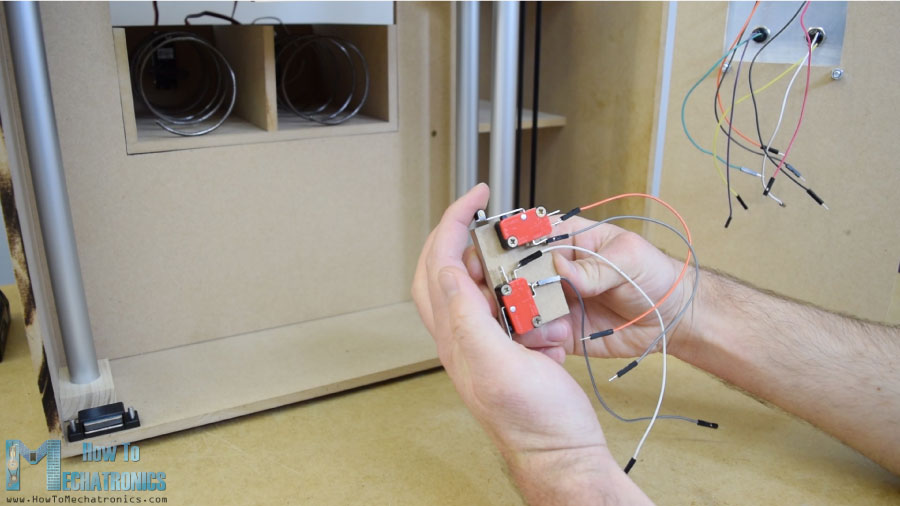
The coin detector is a simple infrared proximity sensor, so when a coin will pass near it, the sensor will give us a positive feedback.
Circuit Schematic
Next comes the fun part, connecting all electronics components to the Arduino board. Here’s the complete circuit schematic for this DIY vending machine project.
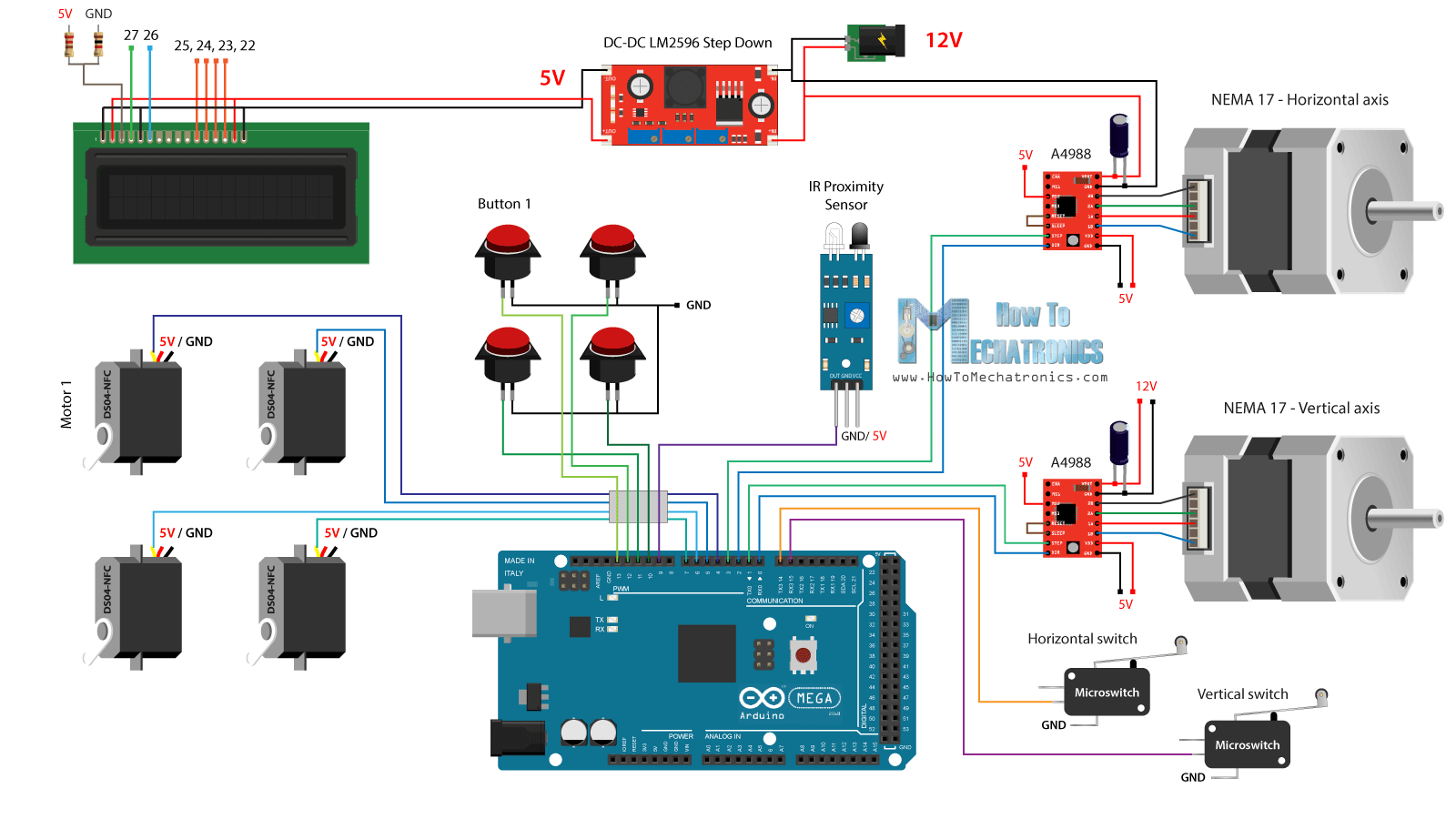
So we need 12V power supply, with at least 2 amps. We need the 12V for the two stepper motors, as well as the LED strip lights which I will later attach on the front door. However, for all other components we need 5V so therefore I used a buck convertor to step down the 12V to 5V. The DS04-NFC continuous rotation servo motors are powered with 5V and controlled via PWM signals coming from the Arduino board, while the stepper motors are controlled via the A4988 drivers. The four buttons and the two micro switches are connected to Ground and the Arduino digital pins, so using the internal pull up resistors of the Arduino board we can easily detect when they are pressed.
You can get the components needed for this Arduino Tutorial from the links below:
- DC-DC LM2596 Buck Converter ………….. Amazon / Banggood / AliExpress
- 16×2 LCD ………………………………………………….. Amazon / Banggood / AliExpress
- 360 Degree Continuous Servo Motor … Amazon / Banggood / AliExpress
- Stepper Motor NEMA 17 ………………………. Amazon / Banggood / AliExpress
- A4988 Stepper Motor Driver ………………. Amazon / Banggood / AliExpress
- IR Proximity Sensor ……………………………….. Amazon / Banggood / AliExpress
- Buttons ……………………………………………………. Amazon / Banggood / AliExpress
- Micro Limit Switch …………………………………. Amazon / Banggood / AliExpress
- Arduino Board ………………………………………… Amazon / Banggood / AliExpress
Disclosure: These are affiliate links. As an Amazon Associate I earn from qualifying purchases.
I connected the electronics components using some jump wires. It became a little messy with that much wires but everything worked properly. At the end I attached two LED light strips on the door panel to illuminate in inner of the vending machine.
Arduino Code
What’s left now is to program the Arduino and here’s the code that I made for this project. Below this there is a description of the code.
/*     DIY Vending Machine - Arduino based Mechatronics Project

    by Dejan Nedelkovski, www.HowToMechatronics.com

*/

#include <LiquidCrystal.h> // includes the LiquidCrystal Library
#include <Servo.h>

LiquidCrystal lcd(27, 26, 25, 24, 23, 22); // Creates an LC object. Parameters: (rs, enable, d4, d5, d6, d7)
Servo servo1, servo2, servo3, servo4;   // DS04-NFC motors

// Stepper motors pins
#define dirPinVertical 0
#define stepPinVertical 1
#define dirPinHorizontal 2
#define stepPinHorizontal 3

#define coinDetector 9

#define button1 13
#define button2 12
#define button3 11
#define button4 10

#define microSwitchV 15
#define microSwitchH 14

int buttonPressed;

void setup() {
  lcd.begin(16, 2); // Initializes the interface to the LCD screen, and specifies the dimensions (width and height) of the display

  servo1.attach(4);
  servo2.attach(5);
  servo3.attach(6);
  servo4.attach(7);

  pinMode(dirPinVertical, OUTPUT);
  pinMode(stepPinVertical, OUTPUT);
  pinMode(dirPinHorizontal, OUTPUT);
  pinMode(stepPinHorizontal, OUTPUT);

  pinMode(coinDetector, INPUT);

  // Activating the digital pins pull up resistors
  pinMode(button1, INPUT_PULLUP);
  pinMode(button2, INPUT_PULLUP);
  pinMode(button3, INPUT_PULLUP);
  pinMode(button4, INPUT_PULLUP);

  pinMode(microSwitchV, INPUT_PULLUP);
  pinMode(microSwitchH, INPUT_PULLUP);

  // Vertical starting position
  digitalWrite(dirPinVertical, HIGH); // Set the stepper to move in a particular direction
  while (true) {
    if (digitalRead(microSwitchV) == LOW) { // If the micro switch is pressed, move the platfor a little bit up and exit the while loop
      moveUp(70);
      break;
    }
    // Move the carrier up until the micro switch is pressed
    digitalWrite(stepPinVertical, HIGH);
    delayMicroseconds(300);
    digitalWrite(stepPinVertical, LOW);
    delayMicroseconds(300);
  }
  // Horizontal starting position
  digitalWrite(dirPinHorizontal, LOW);
  while (true) {
    if (digitalRead(microSwitchH) == LOW) {
      moveLeft(350);
      break;
    }
    digitalWrite(stepPinHorizontal, HIGH);
    delayMicroseconds(300);
    digitalWrite(stepPinHorizontal, LOW);
    delayMicroseconds(300);
  }
}
void loop() {
  // Print "Insert a coin!" on the LCD
  lcd.clear();
  lcd.setCursor(0, 0);
  lcd.print("Insert a coin!");

  // Wait until a coin is detected
  while (true) {
    if (digitalRead(coinDetector) == LOW) { // If a coin is detected, exit the from the while loop
      break;
    }
  }

  delay(10);
  lcd.clear();
  lcd.setCursor(0, 0);
  lcd.print("Select your item");
  lcd.setCursor(0, 1);
  lcd.print(" 1, 2, 3 or 4?");

  // Wait until a button is pressed
  while (true) {
    if (digitalRead(button1) == LOW) {
      buttonPressed = 1;
      break;
    }
    if (digitalRead(button2) == LOW) {
      buttonPressed = 2;
      break;
    }
    if (digitalRead(button3) == LOW) {
      buttonPressed = 3;
      break;
    }
    if (digitalRead(button4) == LOW) {
      buttonPressed = 4;
      break;
    }
  }

  // Print "Delivering..."
  lcd.clear();
  lcd.setCursor(0, 0);
  lcd.print("Delivering...");

  // Depending on the pressed button, move the carrier to that position and discharge the selected item
  switch (buttonPressed) {
    case 1:
      // Move the container to location 1
      moveUp(4900); // Move up 4900 steps (Note: the stepper motor is set in Quarter set resolution)
      delay(200);
      moveLeft(1700); // Move left 1700 steps
      delay(300);
      // Rotate the helical coil, discharge the selected item
      servo1.writeMicroseconds(2000); // rotate
      delay(950);
      servo1.writeMicroseconds(1500);  // stop
      delay(500);
      // Move the container back to starting position
      moveRight(1700);
      delay(200);
      moveDown(4900);
      break;

     case 2:
      // Move the container to location 2
      moveUp(4900);
      delay(200);
      // Rotate the helix, push the selected item
      servo2.writeMicroseconds(2000); // rotate
      delay(950);
      servo2.writeMicroseconds(1500);  // stop
      delay(500);
      moveDown(4900);
      break;

      case 3:
      // Move the container to location 3
      moveUp(2200);
      delay(200);
      moveLeft(1700);
      delay(300);
      // Rotate the helix, push the selected item
      servo3.writeMicroseconds(2000); // rotate
      delay(950);
      servo3.writeMicroseconds(1500);  // stop
      delay(500);
      // Move the container back to starting position
      moveRight(1700);
      delay(200);
      moveDown(2200);
      break;

      case 4:
      // Move the container to location 4
      moveUp(2200); // Move verticaly 4800 steps
      delay(200);
      // Rotate the helix, push the selected item
      servo4.writeMicroseconds(2000); // rotate
      delay(950);
      servo4.writeMicroseconds(1500);  // stop
      delay(500);
      moveDown(2200);
      break;
  }

  lcd.clear(); // Clears the display
  lcd.setCursor(0, 0);
  lcd.print("Item delivered!"); // Prints on the LCD
  delay(2000);
}

// == Custom functions ==

void moveUp (int steps) {
  digitalWrite(dirPinVertical, LOW);
  for (int x = 0; x < steps; x++) {
    digitalWrite(stepPinVertical, HIGH);
    delayMicroseconds(300);
    digitalWrite(stepPinVertical, LOW);
    delayMicroseconds(300);
  }
}
void moveDown (int steps) {
  digitalWrite(dirPinVertical, HIGH);
  for (int x = 0; x < steps; x++) {
    digitalWrite(stepPinVertical, HIGH);
    delayMicroseconds(300);
    digitalWrite(stepPinVertical, LOW);
    delayMicroseconds(300);
  }
}
void moveLeft (int steps) {
  digitalWrite(dirPinHorizontal, HIGH);
  for (int x = 0; x < steps; x++) {
    digitalWrite(stepPinHorizontal, HIGH);
    delayMicroseconds(300);
    digitalWrite(stepPinHorizontal, LOW);
    delayMicroseconds(300);
  }
}
void moveRight (int steps) {
  digitalWrite(dirPinHorizontal, LOW);
  for (int x = 0; x < steps; x++) {
    digitalWrite(stepPinHorizontal, HIGH);
    delayMicroseconds(300);
    digitalWrite(stepPinHorizontal, LOW);
    delayMicroseconds(300);
  }
}Code language: PHP (php)
Source code explanation
First we need to include the Servo and the LiquidCrystal libraries, define the LCD pins, the four servo motors, the stepper motors pins, the coin detector as well as the four buttons and the two micro switches.
In the setup section we set the pin modes for each of the mentioned pins above. We can note that for the buttons and the micro switches pins we activated the internal pull up resistors. This means that the logic level at these pins will be HIGH all the time, and once we press them, the logic level will drop to LOW.
Before we enter the main loop, we also set the carrier to its starting position which is defined by the two micro switches. So with the while loop we keep moving the carrier to its starting position and once the two micro switches will be pressed, the motors will stop and move to the desired starting position.
// Vertical starting position
  digitalWrite(dirPinVertical, HIGH); // Set the stepper to move in a particular direction
  while (true) {
    if (digitalRead(microSwitchV) == LOW) { // If the micro switch is pressed, move the platfor a little bit up and exit the while loop
      moveUp(70);
      break;
    }
    // Move the carrier up until the micro switch is pressed
    digitalWrite(stepPinVertical, HIGH);
    delayMicroseconds(300);
    digitalWrite(stepPinVertical, LOW);
    delayMicroseconds(300);
  }
  // Horizontal starting position
  digitalWrite(dirPinHorizontal, LOW);
  while (true) {
    if (digitalRead(microSwitchH) == LOW) {
      moveLeft(350);
      break;
    }
    digitalWrite(stepPinHorizontal, HIGH);
    delayMicroseconds(300);
    digitalWrite(stepPinHorizontal, LOW);
    delayMicroseconds(300);
  }Code language: JavaScript (javascript)
In the main program, with start by printing on the LCD the message “Insert a coin”. Then we get stuck in the while loop. Once the insert a coin and it pass near the proximity sensor the logic state at the coin detector pin will drop to LOW and in that case we will get out of the while loop using the break statement.
// Wait until a coin is detected
  while (true) {
    if (digitalRead(coinDetector) == LOW) { // If a coin is detected, exit the from the while loop
      break;
    }
  }Code language: JavaScript (javascript)
Then we print the message “Select your item” and we get stuck in another while loop.
// Wait until a button is pressed
  while (true) {
    if (digitalRead(button1) == LOW) {
      buttonPressed = 1;
      break;
    }
    if (digitalRead(button2) == LOW) {
      buttonPressed = 2;
      break;
    }
    if (digitalRead(button3) == LOW) {
      buttonPressed = 3;
      break;
    }
    if (digitalRead(button4) == LOW) {
      buttonPressed = 4;
      break;
    }
  }Code language: JavaScript (javascript)
This while loop waits for us to press any of the four buttons, and once we do that we get out of it and print the message “Delivering”.
Now depending on the pressed button, we execute once of the cases in the switch statement. In case we have pressed the first button, the carrier will start moving up using the custom made “moveUp()” function.
switch (buttonPressed) {
    case 1:
      // Move the container to location 1
      moveUp(4900); // Move up 4900 steps (Note: the stepper motor is set in Quarter set resolution)
      delay(200);
      moveLeft(1700); // Move left 1700 steps
      delay(300);
      // Rotate the helical coil, discharge the selected item
      servo1.writeMicroseconds(2000); // rotate
      delay(950);
      servo1.writeMicroseconds(1500);  // stop
      delay(500);
      // Move the container back to starting position
      moveRight(1700);
      delay(200);
      moveDown(4900);
      break;
}Code language: JavaScript (javascript)
If we take a look at this function we can see that it simply sets the stepper motor to move in a particular direction, and makes the amount of steps that we entered as argument.
void moveUp (int steps) {
  digitalWrite(dirPinVertical, LOW);
  for (int x = 0; x < steps; x++) {
    digitalWrite(stepPinVertical, HIGH);
    delayMicroseconds(300);
    digitalWrite(stepPinVertical, LOW);
    delayMicroseconds(300);
  }
}Code language: JavaScript (javascript)
We can note here that I set the A4988 stepper driver to work in quarter step resolution, and with some tastings I concluded that I needed 4900 steps in order the carrier to get to the upper position. In a similar way we move the carrier to the left until it reaches the location number 1.
Right after that we rotate the continuous rotation motor for 950 milliseconds so that the helical coil make a full cycle.
// Rotate the helical coil, discharge the selected item
      servo1.writeMicroseconds(2000); // rotate
      delay(950);
      servo1.writeMicroseconds(1500);  // stopCode language: JavaScript (javascript)
Note here that these values can sometimes vary and depends on the motor itself. Using the moveRight() and moveDown() custom functions, we bring the carrier back to the starting position. In the same way we can discharge any the four items.
At the end we just print the message “Item delivered”.
So it’s that simple, and I hope you enjoyed this video and learned something new. Feel free to ask any question in the comments section below and check my Arduino Projects Collection.
#include // includes the LiquidCrystal Library
#include
LiquidCrystal lcd(1, 2, 4, 5, 6, 7); // Creates an LC object. Parameters: (rs, enable, d4,
#define coinDetector 9
#define button1 A1
#define button2 A2
#define button3 A3
#define button4 A4
int buttonPressed;
void setup() {
lcd.begin(16, 2); // Initializes the interface to the LCD screen, and specifies the dimensions (width and height) of the display
servo1.attach(11);
servo2.attach(13);
servo3.attach(9);
servo4.attach(10);
Serial.begin (9600);
pinMode(coinDetector, INPUT);
// Activating the digital pins pull up resistors
pinMode(button1, INPUT_PULLUP);
pinMode(button2, INPUT_PULLUP);
pinMode(button3, INPUT_PULLUP);
pinMode(button4, INPUT_PULLUP);
pinMode(8, OUTPUT);
}
void loop() {
// Print “Insert a coin!” on the LCD
lcd.clear();
lcd.setCursor(0, 0);
lcd.print(“Insert Dollar”);
lcd.setCursor(0, 1);
lcd.print(“—————-“);
// Wait until a coin is detected
while (true) {
if (digitalRead(coinDetector) == LOW) // If a coin is detected, exit the from the while loop
break;
delay (10);
lcd.clear();
lcd.setCursor(0, 0);
lcd.print(“Select your item”);
lcd.setCursor(0, 1);
lcd.print(” 1, 2, 3 or 4?”);
// Wait until a button is pressed
while (true) {
if (digitalRead(button1) == LOW) {
buttonPressed = 1;
break;
}
if (digitalRead(button2) == LOW) {
buttonPressed = 2;
break;
}
if (digitalRead(button3) == LOW) {
buttonPressed = 3;
break;
}
if (digitalRead(button4) == LOW) {
buttonPressed = 4;
break;
}
}
// Print “Delivering…”
lcd.clear();
lcd.setCursor(0, 0);
lcd.print(“Dispensing…”);
// Depending on the pressed button, move the carrier to that position and discharge the selected item
switch (buttonPressed) {
case 1:
// Rotate the helical coil, discharge the selected item
servo1.writeMicroseconds(2000); // rotate
delay(950);
servo1.writeMicroseconds(1500); // stop
delay(500);
// Move the container back to starting position
case 2:
// Move the container to location 2
servo2.writeMicroseconds(2000); // rotate
delay(950);
servo2.writeMicroseconds(1500); // stop
delay(500);
case 3:
// Move the container to location 3
// Rotate the helix, push the selected item
servo3.writeMicroseconds(2000); // rotate
delay(950);
servo3.writeMicroseconds(1500); // stop
delay(500);
// Move the container back to starting position
break;
case 4:
// Rotate the helix, push the selected item
servo4.writeMicroseconds(2000); // rotate
delay(950);
servo4.writeMicroseconds(1500); // stop
delay(500);
break;
}
lcd.clear(); // Clears the display
lcd.setCursor(0, 0);
lcd.print(“Item delivered!”); // Prints on the LCD
lcd.setCursor(0, 1);
lcd.print(“Thank You !!!”);
delay(2000);
}
}
This is the code I put for mine and the screen goes crazy. It is the same as yours except I changed some of the pins to be useable with an uno, and deleted the stepper parts. I do not know what went wrong, PLS Help!!!
Hi dejan .Do you give 5V to all of components likes servo and IR sensor and LCD from DC -DC LM2596 or need a 5V adapter or can i give 5V from Arduino mega ?
Hey, you should use the 5V coming from the DC-DC converter for all 5V connections, like the servos, the LCD, the IR sensor, the driver 5V pins as well as you can power the Arduino with those 5V by connecting to the its 5V pin, instead 12V for the Arduino through the power jack.
All things are ok .But when i give power ,2 nema motor work but they don’t rotate like the code..they rotate in only 1 direction and the carrier can’t run .I use Nema 17 1.05A ? Do you think what problem with them ? Do i must buy new nema 17 1.5A or 2A
Hi, I am struggling to make the metal coils? How did you bend the wire and get it to hold its shape?
Thanks
Hey, well as shown in the video, I used a simple spray paint can and wrapped a wire around it. The thing is that the wire needs to be a bit soft, so it can be bend and stay in that position. If you have a strong wire with strong elastic characteristics you might have a problem because the wire will tend to get to its original shape.
Why my lcd is blank ,it is jst showing 16* 2 white boxes ??
Hey, it seems you have a problem with the contrast of the LCD. Try to adjust the voltage on the contrast pin, by using the correct voltage divider, correct resistor values.
Dear Dean I have question about servomotors for this project which is great 🙂
I’m using this S3003 360deg.
My questions are in the comments of the code
servo1.writeMicroseconds(2000); // is this speed for rotation? what is the maximum how do this work?
delay(1539); // is this the time for how long will rotation last?
servo1.writeMicroseconds(1494); // stop for my one servo… for other servo the same brand is other number like 1500 Why?
delay(500);
I can’t make constantly the servo to turn exactly 360 deg every tme… after 2th or 3th turn, it turns 380deg. than 385deg after a while it turns 360deg. again Why is that happening? Is it code, is it electricity… btw the servo is hocked up to external power supply 5v 1.5A brown wire Arduinoground +power supply ground, red wire to 5v power supply, orange to pin9
Hey, well the problem is that these servos are not that reliable and precise. The values used in the writeMicroseconds() generate specific PWM signals. These signals are received by the servo control board and according to them the servo motors rotates. So these values always vary because just like I said, these servos are not that reliable. The delay time is the time how long the rotation will last, that’s true, and if the servos were good and precise, each time the servos should have turned the same degrees. So I guess there’s not much you can do about that.
Hello, Dejan, I am done 🙂
https://youtu.be/FMGZEpP-sgs
Hey, nice work. I’m so glad to see that you were able to make the project. Cheers!
Thank you for all your projects shared!! I don’t have solidworks but fusion360, so can I open the solidworks files thru this program?
You can open the STEP file with Fusion360.
Hey man! Great project!
Can i connect the motors or the lcd to any pins or do they have to be some especific pins?
Hey, thanks! You can connect them any pins, but you will have to define them in the code appropriately.
Im working on this project right now, and was just wondering where did you get the coin guide for the vending machine?
I made it out of sheet metal, you just need to bend it couple of times.
Is it ok to use a 20 tooth GT2 timing belt instead of an 80 tooth? That is the only one I have been able to find so far.
Thanks!
Well the point of the 80 tooth pulley is to reduce the rotational speed. Using smaller pulley will increase the rotational speed so you will have to reduce it in the code.
Is the type of servo motor meaningful (DS04-NFC)? Because I try using Tower Pro MG995 360 degree, but it seem like the motor not act like the desired what actually in the video.
If your servo is 360 degree than it should work the same way. Try to adjust the values a little bit to fit your need.
Hello! I am doing this project at school to introduce students to my school and other schools, but I do not have the program that you used to make the wooden structure with the measurements, could you send me these measures by email?
Thank you,
Best regards
Hey, you can open the STEP file using Fusion 360.
Hi,
I am currently up to building this project and see you use an LED strip to illuminate the machine. What LED strip did you use and if possible could you please include link so I can purchase it.
Thanks
Hi, I am not Dejan, but I used 25 cm cold white LED strip, purchased in local electro shop, so I have not a link on my strip exactly, but I think it does not matter.
Hi, did you have to set somehow trimmer on A4988 because of current? Or just let it be?
Hello, I am a student from Philippines. May i know how can i rotate the servo motor in continuous rotation just like what you did in here? Or can i buy it without opening the servo motor.
Hey, that motor is a different type, it’s continuous rotation or 360 degrees servo. There is a link to it inn the parts list above.
Hi,
I am following your tutorial for a school project this year. I am struggling to find the 16mm and 20mm thick aluminium tube. Where would I be able to purchase this and also where can I find some acrylic.
Thanks
Kieren
Hey, check your local hardware store, the tube doesn’t have to be aluminium, it can be some other material as well.
I have repair it. Servos must have a separate source, and LCD must be powered by arduino 5V GND and the wires must reach everywhere.
Would it be possible to code the machine so it needs 2 or 3 coins to dispense, instead of 1? What would you have to modify in the code to do so?
Sure, it’s possible. You will have to modify the part of the code where we read the IR sensor, the while loop, add some counters and make some logic there for the numbers of coins.
I have got a problem Dejan. When I turn it all on, some servos just clicking instead of normal working and LCD display writes crap or nothing shows, or shows what i want (insert a coin, delivering, etc.), but shines really weak? I do it EXACTLY like you. Do you know what I need to do? Please help, my final year exam is approaching slowly but surely…
Hi. I am building a vending machine similar to yours and I purchased the same continuous rotation servos. When they turn the seem to stop and make a humming noise. Would you be able to help with this? Thanks
Hey, try to adjust the writeMicroseconds() value for the stop.
Hi, I actually solved this damn problem! 😀 The problem was, because
The Chinese have left the potentiometer instead of replacing it with two equal resistors, so the potentiometer is set to a certain position and therefore the servo clicks on one side and turns normally on the other. So you need to play with delayMicroseconds (x); Dejan has, for example, 2000 ms, but I changed it to about 1580 ms, 1500 ms is stopped. It’s not the fastest, but it works as it should. You need to play with the times in the delayMicroseconds () command;
Dejan, thank you very much for this tutorial. Me & my daughter are building this vending machine as a project. We are both somewhat new to electronics & robotics. Could you please clarify/explain the LCD wiring? Where exactly do these wires attach back to?
Thank you very much.
Hey, the LCD is wired as shown in the circuit diagram. If you need more details, you should check my other detailed tutorial on how to connect and use that LCD with Arduino.
Must be microswitches two? It is not enough one? Just modify slightly a program and do it with one microswitch? Or why must be there 2 microswitches, is there some problem? I just need know because I’m just doing this part.
Well if you are building the exact mechanism you will need 2 microswitches. because the a stepper motor does’t have idea about it’s position at start up. It can be anywhere, so that’s why we move it to its initial position, and from there on we keep counting the steps.
OK, thank you very much for your answer. 🙂 Now I only have two:
1) I used NEMA17 12V 1.5A instead of 2A. Do you think that it is a big problem?
2) What everything did you power via 5V GND on the output of step-down module? Did you power something via Arduino? Was there some troubles with it?
Thank you so much.
You can use the 1.5A NEMA17, you should not have a problem. The step-down module is used because the Arduino itself doesn’t have enough power to power the servos. So you can attach everything to the step-down module 5V, including the Arduino 5V (you power the Arduino through that 5V pin).
Can I use coin acceptor instead of IR sensor if so any change in the code should be done . I am not using stepper motors instead I am removing them from my model .Explain why servon.Microsecond(2000) was used while rotating servomotor.Thanks it is a great project and I want learn Arduino after seeing this
Sure you can modify the project in a lot of ways, but for everything you will need to adapt the code. That’s continuous rotation servo motor and that’s how they are controlled, using that function. They are not like regular servo motors that rotate 180 degrees.
Could you tell me the size and number of bearings, screws, bolts, and pulleys used in this work? 3D modeling is a little hard to figure out…
Bearings are 608z, screws are 3mm, bolts M8 and the pulley is GT2 with 80 tooth, you could use this one: https://www.thingiverse.com/thing:339928
You are very innovative. Amazing project – I’m going to build it with my son on his winter holiday.
I’ll send you a pic when I’m done.
one tip – you can convert the 3d model to 3mf – everyone with Windows 10 has MS 3DBuiled now preinstalled… It is a very simple 3d software to work with – no need to be an expert + post conversion all the dimension are kept.
Thank you!
Thank you and thanks for the remark, I will consider it. Have fun building one. 🙂
Hi, Dejan, I’m here again with two questions. First is stepper motors, I bought NEMA 17, but 1.5A, you used 2A, how big is this problem, can I use my actual 1.5A NEMA17 stepper motors, or I need to buy new 2A?
And the second one is how you attached the spring to the servo motor? I appreciate your answers. 🙂
Great Project Dejan. Working with my 8th grader to build this same project, and learning as we go. New to Arduino & programming. We already have some of the hardware components and will get the rest from your recommended links. My question is: where do we get the dimensions of all the wood/metal components and do you have a schematic to put them together. thanks,
Dimensions are in .STEP file, just open it in any program that can open it. https://fileinfo.com/extension/step
I open it in Autodesk Inventor and find out what the dimensions are. But I give you advice: If you want to do it with MDF, choose thicker desks then 8 mm, because of holes for the screws. For example I start to do this project with 16 mm MDF. Just have to recalculate the dimensions.
Thanks for the input!
I could use an arduino uno too right?
Sure, you can use Arduino UNO.
Great project. Can I use matrix keyboard on this project instead of buttons?
Thanks! Sure you could use matrix keyboard.
how many IR avoidance sensor do i need to this project?
I appreciated if someone replies. thanks
I used only one IR senor for detecting the coin when it passes down the guide.
On the diagram it requires 2 capacitors attached between the stepper motor drivers and the stepper motors. What capacitance is required for these?
You can use caps with values around 10-100uF.
Hi!
What kind of 12V power supply did you use?
I used 12V 2A DC adapter.
I love this site! Building a vending machine with my two young kids thanks to you. Dumb question….the 12V 2A DC Adapter you used…is that just a normal adaptor that plugs into the wall and you cut off the other end and connected the wires from that directly to the breadboard for 12 V and the step-down chip to supply 5 V? Or was it some kind of adaptor chip? Thanks!
P.S. I bought all the supplies from your links to try to support you.
Thank you and thanks for the support! Yes, the 12V DC Adapter is just normal adapter. You can either simply cut off the end of the cable and use the positive and negative terminals of the adapter as indicated in the circuit diagram, or you can use a Female power jack so that you don’t have to cut the adapter cable.
OH, I see, dimensions is in the downloadable CAD files , sory for my unnecessary asking 😀
Hello, can I borrow your project on my school work? I mean, create this machine yourself according to your plans and borrow the arduino code? If so, can I ask what are the dimensions of that case? By the way, this is a wonderful project!
Hey, sure you can use the code for such a purpose. Don’t forget to give me credit. Cheers 🙂
So, I’m doing this as a project for school. I can’t open the Solidworks file you’ve provided because I’m using the 2016 educational version.
If you could add a link to one I’d be able to open, I’d really appreciate that.
Thanks!
Try the .step file.
Hello, we are students and we are doing this projekt. Our only problem is that we can not open the messurees and we need them urgently. What can we do? Can you say it here please!
We will be eternetly thankfull
Hey, you should be able to open the STEP file with Fusion 360 and get the dimensions from there.