In this Arduino Tutorial we will learn how to control a Stepper Motor using the A4988 Stepper Driver. You can watch the following video or read the written tutorial below.
There’s also another more comprehensive tutorial on how to control stepper motors with Arduino and the A4988, DRV8825 and the TMC2208 stepper motor driver.
Overview
The A4988 is a microstepping driver for controlling bipolar stepper motors which has built-in translator for easy operation. This means that we can control the stepper motor with just 2 pins from our controller, or one for controlling the rotation direction and the other for controlling the steps.
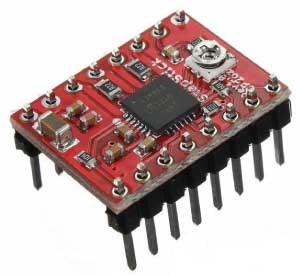
The Driver provides five different step resolutions: full-step, haft-step, quarter-step, eight-step and sixteenth-step. Also, it has a potentiometer for adjusting the current output, over-temperature thermal shutdown and crossover-current protection.
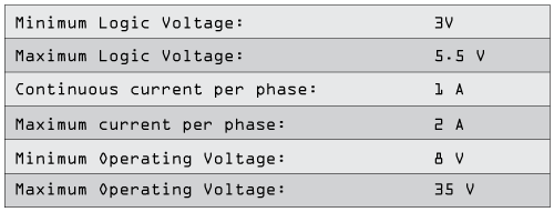
Its logic voltage is from 3 to 5.5 V and the maximum current per phase is 2A if good addition cooling is provided or 1A continuous current per phase without heat sink or cooling.
A4988 Stepper Driver Pinout
Now let’s close look at the pinout of the driver and hook it up with the stepper motor and the controller. So we will start with the 2 pins on the button right side for powering the driver, the VDD and Ground pins that we need to connect them to a power supply of 3 to 5.5 V and in our case that will be our controller, the Arduino Board which will provide 5 V. The following 4 pins are for connecting the motor. The 1A and 1B pins will be connected to one coil of the motor and the 2A and 2B pins to the other coil of the motor. For powering the motor we use the next 2 pins, Ground and VMOT that we need to connect them to Power Supply from 8 to 35 V and also we need to use decoupling capacitor with at least 47 µF for protecting the driver board from voltage spikes.
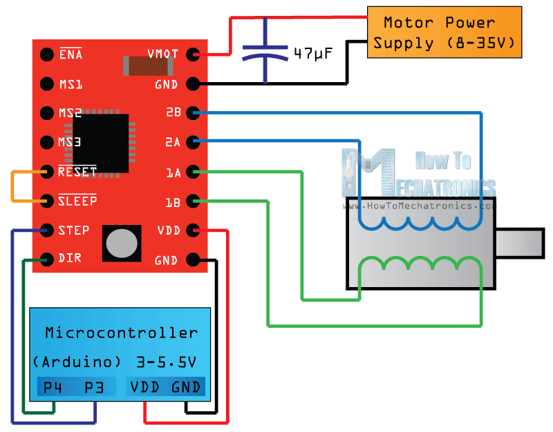
The next two 2 pins, Step and Direction are the pins that we actually use for controlling the motor movements. The Direction pin controls the rotation direction of the motor and we need to connect it to one of the digital pins on our microcontroller, or in our case I will connect it to the pin number 4 of my Arduino Board.
With the Step pin we control the mirosteps of the motor and with each pulse sent to this pin the motor moves one step. So that means that we don’t need any complex programming, phase sequence tables, frequency control lines and so on, because the built-in translator of the A4988 Driver takes care of everything. Here we also need to mention that these 2 pins are not pulled to any voltage internally, so we should not leave them floating in our program.
Next is the SLEEP Pin and a logic low puts the board in sleep mode for minimizing power consumption when the motor is not in use.
Next, the RESET pin sets the translator to a predefined Home state. This Home state or Home Microstep Position can be seen from these Figures from the A4988 Datasheet. So these are the initial positions from where the motor starts and they are different depending on the microstep resolution. If the input state to this pin is a logic low all the STEP inputs will be ignored. The Reset pin is a floating pin so if we don’t have intention of controlling it with in our program we need to connect it to the SLEEP pin in order to bring it high and enable the board.
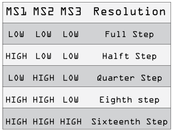
The next 3 pins (MS1, MS2 and MS3) are for selecting one of the five step resolutions according to the above truth table. These pins have internal pull-down resistors so if we leave them disconnected, the board will operate in full step mode.
The last one, the ENABLE pin is used for turning on or off the FET outputs. So a logic high will keep the outputs disabled.
Components needed for this Arduino Tutorial
You can get the components from any of the sites below:
- Stepper Motor (NEMA17)……….. Amazon / Banggood / AliExpress
- A4988 Stepper Driver…………….. Amazon / Banggood / AliExpress
- 12V 2A Adapter………………………. Amazon / Banggood / AliExpress
- Power Jack……………………………… Amazon / Banggood / AliExpress
- Arduino Board ………………………… Amazon / Banggood / AliExpress
- Breadboard and Jump Wires ……. Amazon / Banggood / AliExpress
Disclosure: These are affiliate links. As an Amazon Associate I earn from qualifying purchases.
Circuit Schematics
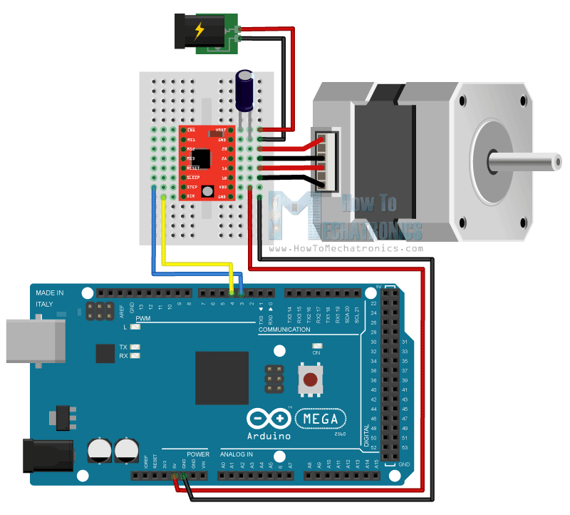
Here’s the complete circuit schematics. I will use the drive in Full Step Mode so I will leave the 3 MS pins disconnected and just connect the Direction and the Step pins of the drive to the pins number 3 and 4 on the Arduino Board and as well the Ground and the 5 V pins for powering the board. Also I will use a 100µF capacitor for decoupling and 12V, 1.5A adapter for powering the motor. I will use a NEMA 17 bipolar Stepper Motor and its wires A and C will be connected to the pins 1A and 1B and the B and D wires to the 2A and 2B pins.
A4988 Current Limiting
Before we connect the motor we should adjust the current limiting of the driver so that we are sure that the current is within the current limits of the motor. We can do that by adjusting the reference voltage using the potentiometer on the board and considering this equation:
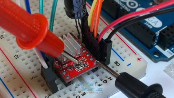
However this equation is not always correct as there are different manufactures of the A4988 driver board. Here’s a demonstration of my case: I adjusted the potentiometer and measured 0.6V reference voltage. So the current limiting should be that value of 0.6*2, equal 1.2 A.
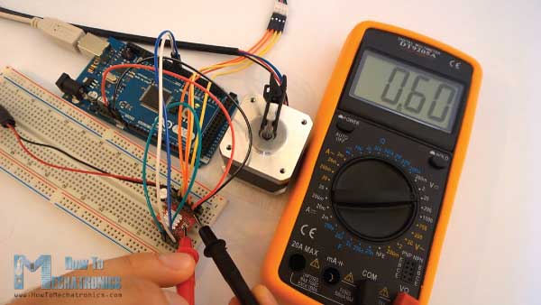
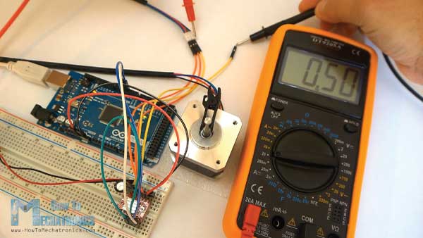
Now because I am using the Driver in Full Step Mode and according to the A4988 Datasheet in this mode the winding current could reach only 70% of the current limit, the 1.2A*0.7 would equal 0.84A. In order to check this I uploaded a simple code that sends continuous logic high to the Step pin (so that we can better notice the current) and connected my meter in series with one winding of the motor and powered it up. What I got was 0.5A which means that the equation wasn’t correct for my case.
Arduino and A4988 Code
Here’s an example code. First we have to define the Step and Direction pins. In our case they are the pins number 3 and 4 on the Arduino Board and they are named stepPin and dirPin and the setup section we have to define them as an outputs.
/*     Simple Stepper Motor Control Exaple Code
 *
 *  by Dejan Nedelkovski, www.HowToMechatronics.com
 *
 */

// defines pins numbers
const int stepPin = 3;
const int dirPin = 4;

void setup() {
  // Sets the two pins as Outputs
  pinMode(stepPin,OUTPUT);
  pinMode(dirPin,OUTPUT);
}
void loop() {
  digitalWrite(dirPin,HIGH); // Enables the motor to move in a particular direction
  // Makes 200 pulses for making one full cycle rotation
  for(int x = 0; x < 200; x++) {
    digitalWrite(stepPin,HIGH);
    delayMicroseconds(500);
    digitalWrite(stepPin,LOW);
    delayMicroseconds(500);
  }
  delay(1000); // One second delay

  digitalWrite(dirPin,LOW); //Changes the rotations direction
  // Makes 400 pulses for making two full cycle rotation
  for(int x = 0; x < 400; x++) {
    digitalWrite(stepPin,HIGH);
    delayMicroseconds(500);
    digitalWrite(stepPin,LOW);
    delayMicroseconds(500);
  }
  delay(1000);
}
Code language: JavaScript (javascript)
In the loop section first we will set the Direction pin on high state that will enable the motor to move in a particular direction. Now using this for loop we will make the motor make one full cycle rotation. As the driver is set on Full Step Mode and our Stepper Motor has 1.8 degrees step angle, or 200 steps, we need to send 200 pulses into the Step Pin to make one full cycle rotation. So the for loop will have 200 iterations and each time it will set the Step pin on high and then low state for making the pulses. Between each digitalWrite we need add some delay from which the speed of the motor will depend.
After this full cycle rotation we will make one second delay, then change the direction of rotation by setting the dirPin on a low state and now make 2 full cycle rotations with this loop of 400 iterations. At the end there is one more second delay. Now let’s upload the code and see how it will work.
I made one more example for this tutorial, where I control the speed of the motor using a potentiometer. Here’s the source code of that example:
/*     Simple Stepper Motor Control Exaple Code
 *
 *  by Dejan Nedelkovski, www.HowToMechatronics.com
 *
 */

// Defines pins numbers
const int stepPin = 3;
const int dirPin = 4;

int customDelay,customDelayMapped; // Defines variables

void setup() {
  // Sets the two pins as Outputs
  pinMode(stepPin,OUTPUT);
  pinMode(dirPin,OUTPUT);

  digitalWrite(dirPin,HIGH); //Enables the motor to move in a particular direction
}
void loop() {

  customDelayMapped = speedUp(); // Gets custom delay values from the custom speedUp function
  // Makes pules with custom delay, depending on the Potentiometer, from which the speed of the motor depends
  digitalWrite(stepPin, HIGH);
  delayMicroseconds(customDelayMapped);
  digitalWrite(stepPin, LOW);
  delayMicroseconds(customDelayMapped);
}
// Function for reading the Potentiometer
int speedUp() {
  int customDelay = analogRead(A0); // Reads the potentiometer
  int newCustom = map(customDelay, 0, 1023, 300,4000); // Convrests the read values of the potentiometer from 0 to 1023 into desireded delay values (300 to 4000)
  return newCustom;
}Code language: JavaScript (javascript)
so i can that Pins MS1 – MS3 connect to the Arduino output pins? for example P7-P9, no need pulldown resistor?
thnks
The MS pins have internal pull-down resistors.
Hi, I connected everything correctly and uploaded the right code, but nothing is happening. Any ideas of what right be wrong? I am using an 11v volt external power supply and a 100uf decoupling capacitor.
Uptade: So now the motor is making this weird buzzing noise and vibrating a tiny bit but not moving like there’s not enough voltage. What voltage is your power supply? Would 12v be sufficient?
Thanks
Very late to reply to this, but check your motor wires. If they don’t match the phases into the driver board, you will get buzzing, vibration, and no rotation. I had a motor whose plugs did not match the pin pairs of the driver – motor connectors. Check your wire pairs for continuity, and you may need to rearrange them if continuous pairs are not adjacent into the driver pins.
Hey Dejan,
Just wanted to say thanks for all the great projects and content you make. I’m a high school instructor and have been teaching robotics for a couple of years (Computer Science is my main area). Anyway, I’ve got some of my 2nd and 3rd level students creating some of your projects and they’ve been really well received so far (Strain Wave Generator, Color Candy Sorter).
Really awesome work!
Hey, I’m so glad to hear that. Thanks!
Dejan, this has helped so much!!
I do have a question:
I am hoping to trigger my stepper on linear actuator to turn on, move one direction, then reverse and come back to original start location. I want to use a micro switch to trigger the process.
Is this done all with code? Will I need to configure pins different from what this tutorial shows?
Thanks again!!
Well I guess you would need few “if” statements to tell the stepper what to do when the micro switch is triggered. The pins configuration for the driver will be all the same, you just need to define the micro switch trigger as digital input and use the “if” statements to tell the stepper what to do.
I’ve been working on your 4988 board/arduino system for controlling a stepper motor. I have the arduino/4988 board and motor connected as per your drawing. My problem is the code you published won’t load into the arduino. It hangs up at the last line: delayMicroseconds(500);
It says that a” ; is expected before Microseconds.”
What is the cure for this? I’ve tried everything I can think of with no luck.
Thanks, I find your projects well written.
Hey, I’ve just check the codes and they work fine. It seems like your error comes from missing the “;” character at the end of some line.
Hello Dejan,
I am trying to run three stepper motor wth Arduino mega 2560. my goal is to run all three motors together but the number of steps would be different. I’ve tried using Adafruit Motor Shield V2, A4988 driver and also by directly connecting to Arduino, but so far all motors are not running simultaneously and with shield, they run together but just one step at a time and it takes a long time to reach my desired steps. can you just share how can I solve this?
My stepper Motor: Saia UCD10N28R, Step Angle 7.5, Rated Voltage 6V, Coil resistance 24Ohm, Steps/Rev 48
Aim: max 1200Steps of stepper motors time needed should be less than 5 sec (all three together)
Hey, I would suggest to try the AccelStepper library, it has really good functions to control multiple stepper motors. You can check some of my other tutorial/ projects where I used this library, for example the camera slider, the wire bending machine, etc.
Great theoretical and practical explanations. Easy to understand and follow. You would be a good lecturer. Best
Thanks, I’m glad you found it useful!
To add (in case you find it useful for a future project). I’ve just implemented a dual current limit which works really well. This allows you to run a high current for moving, (so you can accelerate a mass quickly etc) and a low current for braking.
I am using this on a linear stage in a small robotics project, with out the dual current limit I would be forced to run at a current limit set by the thermal performance of the chip/heatsink. There are many ways to implement the switchable limit, but for many projects having the the high peak current and a low hold current is thermally/performance beneficial.
Thanks again
Rob,
Hi, thanks for the interesting write up. A quick (maybe silly) question – does the motor brake when you are not toggling the step input? Ie, is current still flowing through the windings?
If this is the case (i think it must be) does the sleep input pin allow you to release the motor?
Cheers!
Hey, thanks! Yes, that’s right, the current is still flowing through the windings when the motor is not moving, it holds its position. And yes, the sleep or enable pins can be used for releasing the motor.
Great, thank you Dejan!
Hey, great video! Could I power this with enough AA batteries in order to create 12V? If I use batteries do I still need a capacitor? And also, could I add a resistance and create the 5V for the boards with these same batteries?
Thanks!
Hey, no you cannot really power NEMA 17 stepper with AA batteries. This stepper can draw up to 1A of current. You could use Li-ion 18650 batteries or Li-PO batteries.
Very useful for my Picaxe projects. You explain in a clear, concise manner. Many thanks for the effort of producing this how to guide.
Thanks!
Hi.
Great tutorial! I followed and have everything working. Would you mind explaining how to convert this into 1/16 microsteps using the MS Pins? What code needs to be added? Thank you for your help!
Hey thanks! For 1/16 micro steps resolution you just need to connect HIGH or 5V to the three MS pins, just like seen on the MS truth table in the article.
Hello Dejan,
Trying to control a stepper motor with a manual pulse generator (hand wheel type). Is this possible with the A4988? If so, any help in this direction would be greatly appreciated. Thanks.
Well as you have probably noticed the A4988 has a STEP pins, which of triggered from Low to High it moves the motor a step. So if you make such a generator that generates that type of pulses you should be able to manually control the steps.
Hello sir. How about if the stepper motor is connected to a belt and the positons (steps and direction) are controlled using push buttons? Is it possible? If it is possible, can you give me some pointers or things to remember? I am developing an automated arbiter of the game of the generals (if you are familiar with this game) and an stepper motor is needed to position the robotic arm in 8 rows of the board.
It’s possible for sure. You just assign a what the stepper should do when the particular button is pressed. You can see the commands from the explained code above (change direction, make the stepper move one step, multiple steps etc), so you just need to implement them appropriately when a particular button is pressed.
Excellent Tutorial !!! I do have a question though. For my application, I have the motor go back and forth about 1/4 revolution and I repeat this 5000 times and then I want it to stop.
I can stop it in the code, but the motor is locked in position and keeps getting hotter the longer it is plugged in. Is there a way in code to release or disengage the motor so that it doesn’t keep getting hotter?
In order the motor to stay in play you need to keep the motor active all the time. You could try to lower the current draw of the motor by adjusting the potentiometer on the A4988 driver, and in that way lower the motor heat.
Hello Mr Nedelkovski,
My name is Hristo, from Plovdiv, Bulgaria. My experience in mechatronics is too short, but this
matter is very interesting for me.
I have watched your video “How To Control a Stepper Motor with A4988 Driver and Arduino”
and made successful attempt with one stepper motor. Your program code is so simple and
understandable. Can I rotate 2 or 3 steppers “simultaneously” with any similar way?
Best wishes from Hristo
Check my DIY Camera Slider project where I use the AccelStepper library for controlling 3 steppers simultaneously.
The information you provide is excellent, not only here, but all the projects you publish. I am looking at driving 4 separate stepper motors with an Arduino mega, however the LCD uses all of the available PWM pins, do the STEP and DIR pins have to be PWM pins, or can I use any of the digital pins (like pins 22-53)? I noticed all the stepper libraries I have found need to use PWM pins to work.
Thanks for the great work!
Thanks! Well the STEP and DIR pins actually don’t need to be connected to PWM pins in order to be able to control the motor with the A4988 driver. However, there might be some libraries that use them for controlling the stepper.
love…. Thanks alot homie.
Great guide! I am about to build my own CNC 2D plotter using DVD drives motors + A4988. Do I have to make some preset of X and Y axis position? I am afraid about damaging stepper motors. Could it happen that motor wants to move in X-axis but it is already at the end of range = damaged motor? Do I need end stops to prevent this? Thanks!
End stops are definitely recommended have for such an application.
How do you wire the 12V 2A power supply to the breadboard? Do you cut the wire then insert the positive and negative ends? All I can see in the pictures/video is two red and black wires but never how they are connected to the power supplier. I purchased the same power supplier that you provided through the link above.
Yes, that’s how I did it, cut the wires and soldered two jumper wires to it for easier connection to the breadboard. However don’t have to do that, just get a 12V Adapter Jack. I should’have added a link to it earlier, but updated it now.
By the way, thanks for the support!
Hello and nice work! I i try this tut but with little differences(32μF cap and 9V battery).
I upload the code and i can hear the steps (500 microseconds) but the motor dont turn.the circuit is correct. Is it possible that the 4 wires of the motor are not like your schematic?
Your battery might not have enough power to drive the motor.
Hello Dejan
I want to do this work by these device. can you tell me the datasheet of stepper motor (or model that used to rotate 2 Kg plate that work in this project)and voltage and amper of adapter?? because I am beginner. Thanks alot
What happens if i put 9V instead of 12V?
It should work as long the power supply has enough power. It’s already stated that the operating voltage of the driver is from 8V to 35V.
I tried the same circuit with NEMA 17. The Stepper is not rotating but just making some noises. With slight pressure tangential to the shaft it is making a microstep movement.I used set a 3 HW 9Volt batteries as external power source to the stepper at VMot and Gnd. What should be done?
The problem is the battery, it doesn’t have enough power. You should use an DC adapter power supply rated at least 2A.
hi everybody
I have a question
The model of my stepmotor is 23Hs and in its datasheet write that it need to 12 V and 3 Amper current. Now we should connect 12V ,3 A adapter???
That’s correct, but your wont’t be able to use the A4988 driver as 3A is too high for it.
I’m using 17hd1402-01n model step motor.and I also using your codes the above.but when I try to use delay time as 500ms my motor never turn any direction .it is only vibrating.if I set delay time to 1000ms my motor turning . I want to ask you,why my motor don’t turn below 1000ms delay time?I also using a4988 .what is the actual problem.is it step motor or what ?
thanks and best regards
Well it seems that the motor doesn’t have enough power to start rotating with that small steps. Check your power supply amps rating, make sure it has enough power for driving the motor.
Hi buddy
Thank you for your practical tutorial and video. i have done the same procedure but i have a uni-polar 5 wire stepping motor and it just vibrate instead of rotating. i can feel just small movements in motor.
could you help me with that?
Try increasing the delay time between the steps. It seems like the motor doesn’t get enough power.
Hi,
I’m planning on using this with an Arduino UNO, however, the A4988 stepper driver says it’s compatible with Arduino Mega2560. Does this work with an arduino UNO?
Thank you in advance.
Sure, it’s compatible with Arduino UNO as well.
Hello Dejan,
thank you for your reply.
So it is not a problem to connect the power supply through one of the driver? The second stepper is getting enought power through the arduino and the driver number one? Which pins would you use on the microcontroller? P3/P4 and VDD/GND is for driver number 1. Certainly i could use P5/P6 for driver number 2. But is there a second pair of VDD and GND pin?
Thank you so much!
Great tutorial, thanks for publishing!
I would like to run two steppers with one arduino and 2 A4988 but with one power supply. Could you please tell how to insert a second stepper?
Thank you so much!
Best regards
Markus
Thanks!
Well it should be much of a problem. You just need to add another driver and connect it the same way as the first one. Also modify the code is similar way.
You can use the same power supply for the motors but just make sure it has enough power to power both motors.
Hello Dejan,
thank you for your reply.
So it is not a problem to connect the power supply through one of the driver? The second stepper is getting enought power through the arduino and the driver number one? Which pins would you use on the microcontroller? P3/P4 and VDD/GND is for driver number 1. Certainly i could use P5/P6 for driver number 2. But is there a second pair of VDD and GND pin?
Thank you so much!
Does anyone know where I can get library files for A4988 to use in Diptrace PCB artwork program. Thanks
Really good tutorial – showing how to adjust current limits. One should be cautious not to make a short circuit between GND and VDD – like I did. That cost me an Arduino Nano….
Thanks. Yeah, that’s true, you should be cautious about it, I should have mentioned that in the video. I’m sorry to hear that about your Arduino.
Hi Dejan.
Being new to arduino could you please explain for me. In the first example I assume the motor is driven at ‘full speed’ all the time. Then in your second example you alter the speed of the motor using a potentiometer. My question is I want the motor to work at a slow speed all the time, can the potentiometer be replaced by a determined resistor or can it be controlled by a extra line of code in the initial sketch?
Hi there. Well in my example the speed of the motor is controlled by adjusting the delay time between the steps of the motor, or if you that a look at the code that’s the following line:
delayMicroseconds(500);
So all you have to do is set this value according to your need.
Just found your website and the answers to what has has been puzzling me regarding stepper motors. I would like to say thank you for such a well presented precise explanation of how things work and more importantly what is going on in the background, not only have you shared your knowledge but you have also took the time to answer questions. This should be used as a bench mark of how other internet websites/forums should be. THANK YOU for taking the time to teach others !!
I’m so happy to hear this, thank you!
Hi Dejan, thanks for your useful tutorial.
I’ve got a question, is it possible to control 2 stepper motors at the same time by using 2 drivers? The motor rotation is not the same, for example, I want the first motor to rotate 400 steps CW and the others 800 CCW starting at the same time.
I’ve already tried to write the code for it, but it the motor doesn’t rotate together, motor B will only starting to rotate after motor A finish rotating.
Thanks for your help!!
Sure it’s possible to drive the motors the way you described you just need to make the right code for that.
Hi Dejan!
First of all, thank you for sharing your tutorial. It is very usefull.
I have a question with the script in wich i have to use a potentiometer, ¿Is there a way to measure the motor rpm? i mean, i want to know how many revolutions per minute is the motor when i set the potentiometer to a particular state.
Thanks a lot!
Well you will need an encoder for measuring the rpm of the motor. Or you could calculate the rpm if you measure the time the arduino needs to execute the 200 steps (full cycle).
Dejan, great tutorial. Do you mind answering as to what the difference is between this driver and the one used for the 28bjy-48-stepper? Are they interchangeable or each stepper needs to have their own driver board? The one used in that video is much cheaper”
Thanks,
Mark
Thanks. Sure there is a difference between the drivers. Even if you just look at the basic stats of the drivers you can notice a big difference. Just because one is cheaper doesn’t mean it has lower performances.
Hi Dejan,
Thank you for this great tutorial. I have two questions: in the video, the circuitry diagram (the one that looked like a Fritzing image) does not show that the Sleep and Step pins are connected. Yet it appears as if they are at the end of the video? Could you clarify for me which is the correct circuit?
And secondly, more importantly, I am finding that my stepper motor, an FSM0815-KD95, is getting extremely hot. After checking the voltage of the 1A-2B driver pins, I found that even when my code was simply looping “digitalWrite(stepPin, LOW);” two of the pins are still receiving voltage. Is there anyway that I can make the voltage of all pins 0 while the motor is not running? That way it will not overheat.
Hi there and thanks!
“Step” pin is connected to Arduino, of course, because it gives controls the steps of the motor.
“Sleep” pin is connected to the “Reset” pin of the driver.
The motor supply voltage of the A4988 driver is 8 – 35 V accross the VMOT and GND, so your motor might not be suitable for this driver.
Great tutorial and thanks. I am up and running thanks to you.
My only issue is that my NEMA 17 running on an A4988 controller and Uno board is that it will only run one direction. Changing the code does nothing. I can get a direction change by switching the wires around at the controller, but not by changing the code.
I am very new at this so hopefully it’s something simple.
That’s strange. Currently I don’t have anything on mind to say about it. It could be a drivers fault…
Dejan,
thank you very much, but, can you please better explain that part about current limiting? I have source 12V 1500mA (motor same as you), what should i measure and what to change? I don’t understand it, thank you
what type of capacitor should i be using because you said to use a 47 microfered capacitor but the diagram said to use a 100 microfered.what capacitor should i use
motor: [link]
cheers
Well it should be used at least 47uF.
My 47uF blew on 12V. 100uF works.
Thanks for the remarK!
Hi Dejan,
Thank you for sharing this tutorial.
Just wondering; you used a NEMA 17 42BYGHW609 (the ‘get one’ link refers to this type)? It is rated at 3.4 V and 1.68 A.
Now, the A4988 has a minimum operating voltage of 8 V. Actually, you prescribe a 12 V, 1.5 A power source. Does this not lead to any conflicts?
Cheers, Olaf
Yes the 8V – 35 V are the Motor Supply Voltage so you can connect any adapter you want within that range. The driver will take care of the driving the stepper with the appropriate voltage.
Hi Dejan Nedelkovski, congratulation and thank you for sharing this tutorial.
According the Delay control the speed of the stepper motor in your code, you wrote a delay (500 microseconds). your mapping delay for the potentiometer is between (300; 4000).
My question … Where did you found these values and their limits ?
Thank you for your answer
Jimmy
Hi there. Well I made tested them. For example If I set the delay time lower then 250, i think, the stepper wouldn’t start at all. The lowest delay time (fastest speed) I managed to try was like 90, but with higher delay at the start, more then 300, then lowering with the potentiometer to 90.
Also you could find more details about this, the timing, in the datasheet of the stepper driver.
Thank you for the Reply and sharing this tutorial.
Best Regard.
Respected sir,
Myself Manas Bose, Sir I am working on a project, where I have to control a stepper motor step control with the help of a potentiometer, and arduino the sir I have wrote a skech with the help of a friend attached herewith, it is working fine.
Sir now I want to make this thing wireless, sir I want to use 2 arduino and 2 xbee, on sending side a arduino, xbee, and a potentiometer will be there. On receiving side a arduino, xbee and a stepper motor will be there. Earlier one setup I made with servo motor.
Sir, I and my friend don’t have adequate knowledge of c ++, I hereby request u to kindly help
In the coding, or at least if u can throw some light on it.
Hope to be favored please
Thanking you
Manas
#include
int current_position = 0;
const char direction_pin = 2;
const char step_pin = 3;
const char pot_pin = 1; //analog input 1
void setup()
{
pinMode(direction_pin, OUTPUT);
pinMode(step_pin, OUTPUT);
pinMode(pot_pin, INPUT);
}
void loop()
{
int readvalue = analogRead(pot_pin);
readvalue = map(readvalue,0,1023,0,1151);
if (readvalue > current_position)
{
step_motor_forward();
current_position += 1;
}
else if (readvalue < current_position)
{
step_motor_back();
current_position -= 1;
}
}//end of loop
void step_motor_forward()
{
digitalWrite(direction_pin, LOW);
digitalWrite(step_pin, HIGH);
digitalWrite(step_pin, LOW);
}
void step_motor_back()
{
digitalWrite(direction_pin, HIGH);
digitalWrite(step_pin, HIGH);
digitalWrite(step_pin, LOW);
}
I don’t have any tutorial for the Xbee so I can’t help you much with that.
Hello, nice tutorial. May I ask what is the difference to drive the motor in Full Step Mode and microstep mode and how to change between the modes?
Check my Stepper Motor – How It Works article in order to understand the difference of the modes. And as for this driver, selecting different modes is already explained in the post itself.
I have a cuestion , can regulate the speed of UN NEMA 17 with 4 letters of my computer, for example letter a = 0 speed, b= 25 %, c =50 % d= 100, i don want use potentiometer
Sure you can, but you have to make a program for that. You could use the Arduino Serial Port to send these signals or use Processing IDE in order to make even cooler interface.
can you help me? im a confused i dont know where to star, i have this materials, Testing A4988 + NEMA17 + Arduino, i dont have idea how to regulate the speed
I think that is more dificult to have the control of the motor bipolar u.u that motor cd and you have a razon i need to use a serial port
Respected sir,
I have seen your video on How to control a stepper motor it is a good and nice
tutorial.
sir I have question, sir I want to control a stepper motor’s rotation angle from
0 to 360 and 360 to 0,with a potentiometer. sir there is an example skech in the Arduino software, called
stepper motorknob. sir in that example skech four control inputs are there,
by using A4988 driver board that skech is not going to run the motor.
sir please throw some light on this.
or can u suggest some skech on this without using library
thanking you
Manas
Well I don’t have such a code. But here’s a tip how you make that: map the potentiometer values from 0 to the number of steps the stepper motors needs to make a full 360 cycle.
Thanks for this tutorial, I have used your information to successfully get my A4988 board & stepper motor project working. It saved me a lot of time! But I did have to change the stepper wiring, the illustration shows the wires straight through from the motor into the A4988 board, but I had to cross them over. My stepper is a NEMA 17HS3001-20B it has 4 wires and similar looking connections on the motor. Would it be worth adding a warning about this in the next version of your page?
I’m glad to hear you’ve found it useful! Well there many different manufactures of these motors so each of them might have different order of the pins. So therefor, before connecting, you should always check datasheet of the motor.
Gracias, excelente tutorial, sin ningún problema.
Saludos cordiales
Hi, I’m building a rubiks cube solving robot using a A4988 driver and bipolar stepper motor for each face of the cube so this article is perfect for me! I’m documenting the project on twitter, see @robertfriberg
Question: I saw a different tutorial where the grounds between the power and logic circuits are connected. It seems you don’t connect the grounds. What’s the difference?
Well, you don’t have to connect them together as they are already connected. The two GND pins of the A4988 board are already internally connected together.
Great tutorial! I got everything to work with the potentiometer after playing around with it for a bit. Now I want to add another motor/potentiometer to the same Arduino board. I tried copying everything you had in potentiometer code and just renamed and add a few variables. I was successfully flashed my code to my Arduino Uno but when I changed one potentiometer both motor speeds would change at the same time. I can’t figure out how to get each motor to work independently. Any suggestions?
It got to be the code. In the tutorial example with the potentiometer value we change the delay time between the steps. So you need to make separate delay variables for both motors. You could achieve that if you make separate custom functions outside the main “loop” for both motors so that they have separate delay variables and then you just have to call those custom functions in the main “loop” to be executed.
Did you get me?
I think I got ya. Here’s what I have. Still learning Arduino code. I the stepper motors don’t want to work independently.
void loop() {
customDelayMappedFeed = speedUpFeed(); // Gets custom delay values from the custom speedUp function
// Makes pules with custom delay, depending on the Potentiometer, from which the speed of the motor depend
digitalWrite(stepPinFeed, HIGH);
delayMicroseconds(customDelayMappedFeed);
digitalWrite(stepPinFeed, LOW);
delayMicroseconds(customDelayMappedFeed);
customDelayMappedCut = speedUpCut(); // Gets custom delay values from the custom speedUp function
// Makes pules with custom delay, depending on the Potentiometer, from which the speed of the motor depend
digitalWrite(stepPinCut, HIGH);
delayMicroseconds(customDelayMappedCut);
digitalWrite(stepPinCut, LOW);
delayMicroseconds(customDelayMappedCut);
}
// Function for reading the Potentiometer
int speedUpFeed() {
int customDelayFeed = analogRead(A0); // Reads the potentiometer
int newCustomFeed = map(customDelayFeed, 0, 1023, 300, 4000); // Convrests the read values of the potentiometer from 0 to 1023 into desireded delay values (300 to 4000)
return newCustomFeed;
}
// Function for reading the Potentiometer
int speedUpCut() {
int customDelayCut = analogRead(A1); // Reads the potentiometer
int newCustomCut = map(customDelayCut, 0, 1023, 300, 4000); // Convrests the read values of the potentiometer from 0 to 1023 into desireded delay values (300 to 4000)
return newCustomCut;
}
Hi Nick,
I did the same but it seems like the first pot delay time is added to the second pot delay time.
How did you deal with that?
I can’t seem to fined any updates to your post.
Hello again, in your code with the potentiometer, in your function you have the following code : int newCustom = map(customDelay, 0, 1023, 300,4000); // Convrests the read values of the potentiometer from 0 to 1023 into desireded delay values (300 to 4000). My question is, How exactly you found the desirable delay values ? My motor is an Nema 17 stepper motor . Thanks in advance (I’m trying to control 3 motors wireless in my project 🙂 )
Hello I’m trying to control a stepper motor with a joystick, a DRV8825 and an arduino uno. I used your tutorial with the potentiometer, but I have some difficulties with the speed . In your tutorial you have only one direction and your values are from 0 to 1023. I want to devide the potentiometer for RIGHT and LEFT direction, any suggestions on how to do that? Also, the speed on my motor is slower than your tutorial(When the motor turns clockwise and anticlockwise). Thanks in advance, still your tutorial was very helpfull.
Well you should adjust the delay time between the steps that will suit your driver and stepper capabilities and match your desired speed. As for the potentiometer you should use the map() function and try to map the values you get from the potentiometers into the suitable delay times, as well, probably with an “if” statement, for half of the values make the “dir” variable positive or negative.
Thanks for the reply, I manage to fix it and it runs smoothly. Thanks again for a wanderfull tutorial !
Hi’
Thanks for this tutorial. I’ve been trying for weeks to run 3 steppers on a Uno with a motor shield and A4988’s. I’ve had no success at all and thinking I had fried everything, bought full replacements, with the same results. Thanks to your tutorial I’ve at last managed to get a positive result. I’ve also now been able to test all the A4988s, my 2 Uno boards and the steppers. Interestingly, I didn’t fry anything! I’ll now need to think about how to test the shields.
Thanks again, Ralph
I’m glad to hear you found it helpful!
Hi there. Joining others. Really comprehensive and useful and worth all congrats. Bookmarked!
Thanks!
Hello Dejan,
Thanks for great tut. I followed your tut same. But result is like on the video. After I connecting stepper’s wires to a4988 its like vibrating. Its like affecting kind of magnetic field. It is strange. After I connect the arduino result is like on the video. What can be the problem.
https://www.youtube.com/watch?v=QeQ7apxoEZs
Thanks.
Hi there,
As I can notice the stepper might be skipping steps. Try to increase the delay time between the steps. What power supply do you use?
Now its working! I did everything same. How its possible. I am using 12v for powering the stepper 5v for logic. But i was not shure about which coil cables which. I had tried all the combinations. But now its working… Great!.
Thank you so much.
Difference was, I earlier took logic power from another source. Now I am taking it from Arduino. For who encountering same problem.
Cheers!
Good to hear it solved your problem!
HI, thanks for the good tutorial. I am using the code you wrote with the potentiometer. However, even when I change
digitalWrite(dirPin,HIGH); //Enables the motor to move in a particular direction
TO
digitalWrite(dirPin,LOW); //Enables the motor to move in a particular direction
The motor keeps going in the same direction – any idea why?
thanks
Well that’s strange. Try reconnect the driver exactly as explained and try the code again. There’s nothing else you can do, because the DIR pin of the driver is meant for that. Either is LOW or HIGH and the motor should move in different direction.
Hello
I have a question, could you show the scheme with the potentiometer?
I don´t know how conect this.
thaks a lot
Andres
You can find more details about that on my Arduino Analog Inputs Tutorial:
https://howtomechatronics.com/tutorials/arduino/analog-inputs/
Thanks!, great tutorial!!!
Yep, thanks!
Please help with matlab and a4988 as I have been trying to Abd unsuccessful.
I haven’t tried that combination. Sorry I can’t assist you with that.