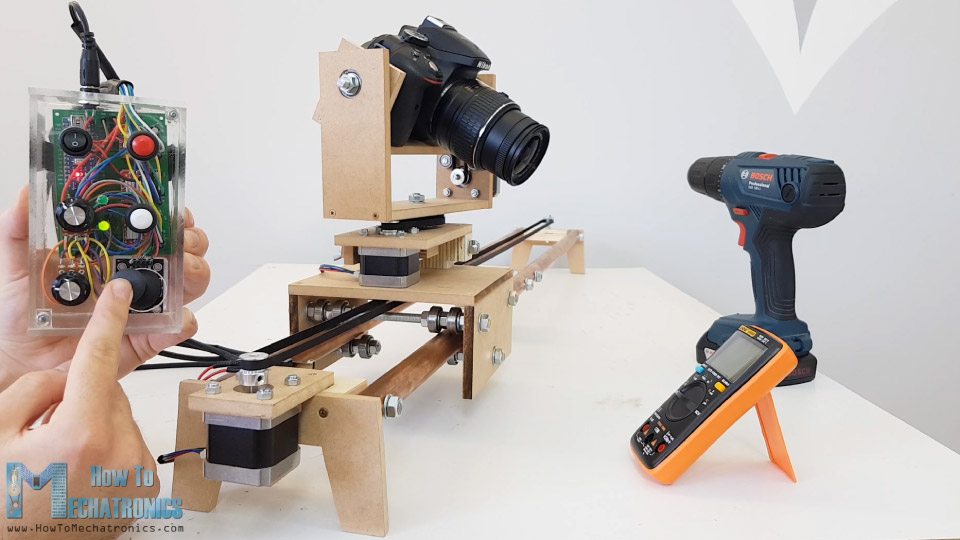
In this tutorial we will learn how make a motorized camera slider with pan and tilt head. This Arduino based project is 100% DIY, built with cheap materials like MDF and plywood and controlled using Arduino, three stepper motors, some buttons and a joystick attached on a custom designed PCB. Despite this, the end result is quite impressive, with super-smooth camera moves enabling us to get professional looking cinematic shots.
You can watch the following video or read the written tutorial below.
Overview
Using the controller we can either manually move the camera around or we can set start and end points and then the camera will automatically move from one to the other position. Also using the supporting arm we can mount the slider even on a smaller tripod, at any angle we want and still get a stable movements.
To begin with, I designed the slider using a 3D modeling software.
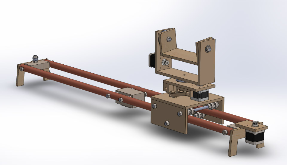
You can find and download this 3D model and get all dimensions from the 3D model below, as well as explore it in your browser on Thangs.
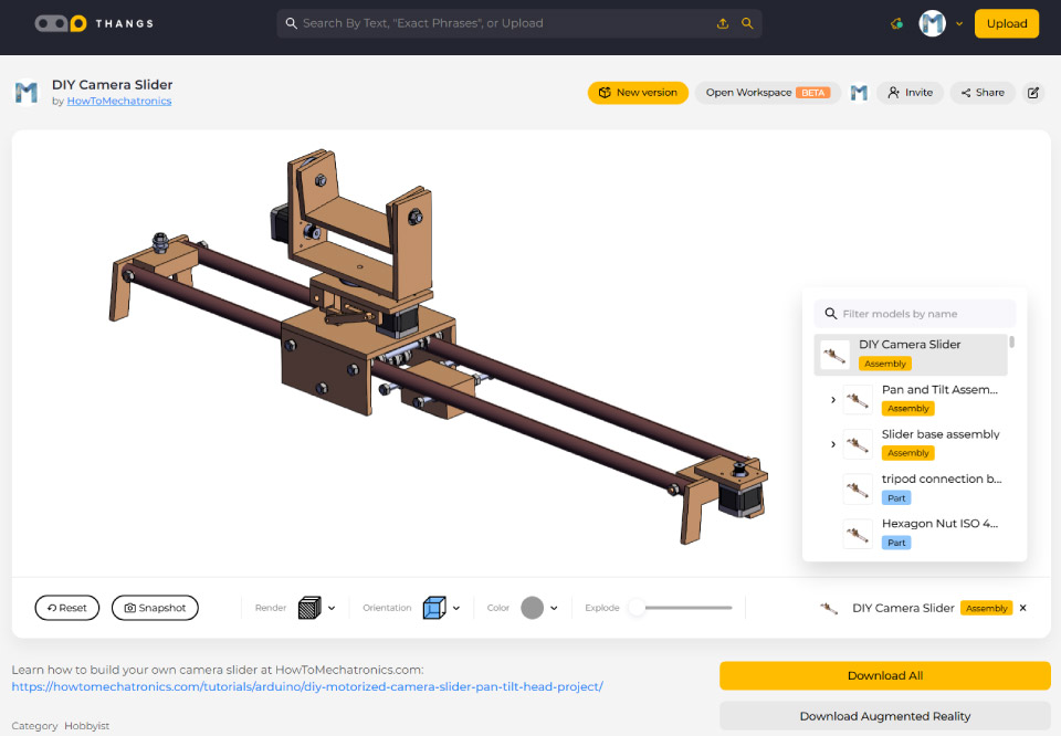
Download the assembly 3D model from Thangs.
3D Printed GT2 pulley link:
Building the camera slider
So I started with making the slider rails for which I used 22mm tick copper pipe. I decided to make the slider 1 meter long so I cut two pieces to 1 meter of length. Copper pipes can easily oxidize so therefore we need to polish them with a metal polish. In my case, I didn’t have one so I used a toothpaste for that purpose.
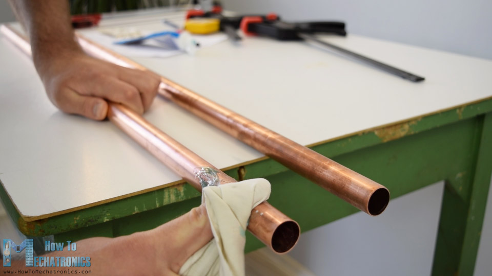
This wasn’t the perfect solution bit still I could notice a difference and got the pipes a bit cleaner.
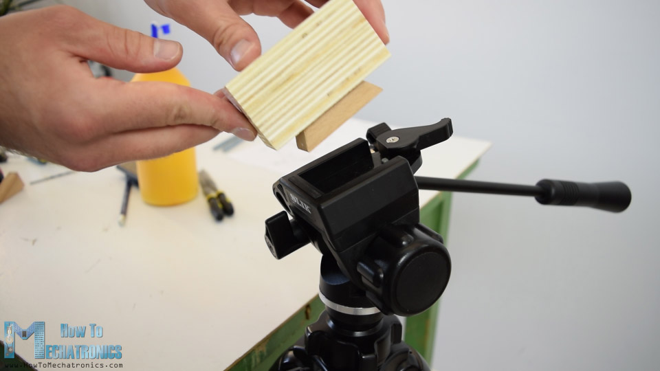
Then I moved on with making the wooden base on which the two pipes will be attached and also it will serve for mounting the slider onto a tripod. Using a circular saw I cut two pieces of 21mm tick plywood and glued them together in order to get a single ticker piece. Then using a solid wood I made a replica of my tripod mounting plate and attached it to the plywood piece using a wood glue and a screw. Now the slider base can be easily mounted on the tripod.
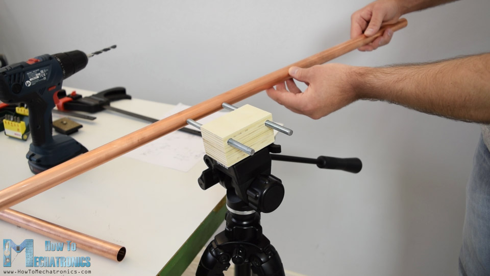
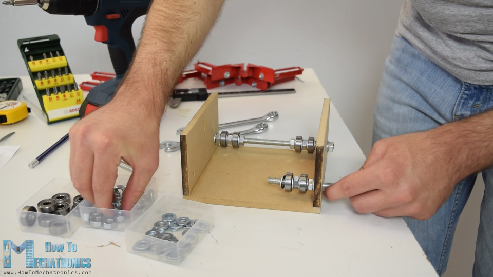
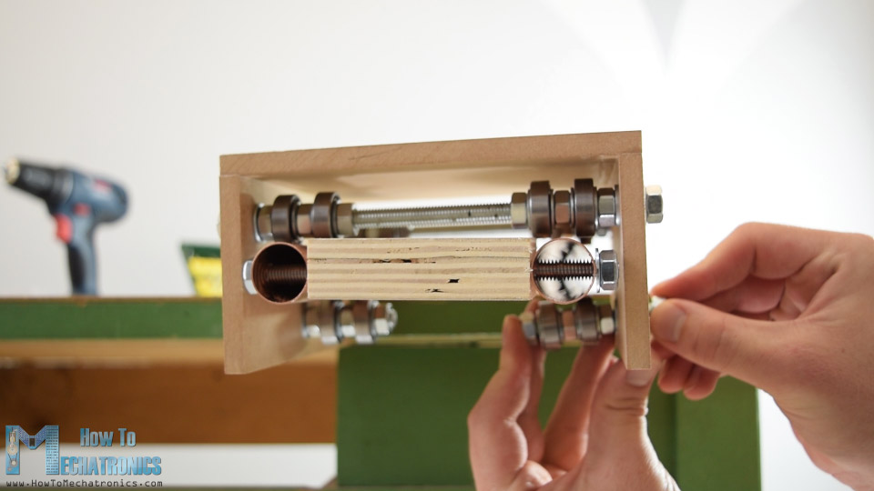
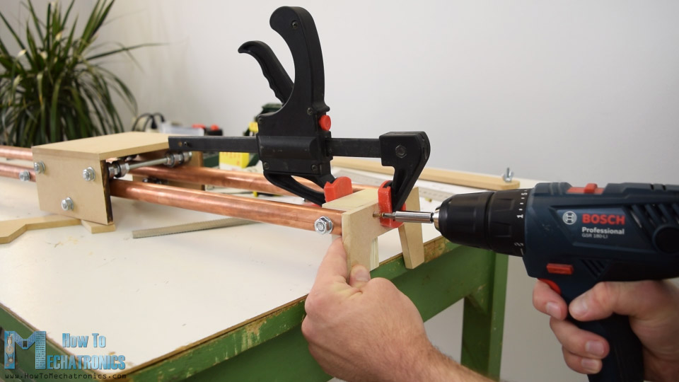
I will mount the slider rails to the base using 8mm threaded rods so I made two holes in the base and inserted the 138mm long rods which I previously cut them to size. Next I had to drill 8mm tick holes in the pipes which can actually be a little tricky.
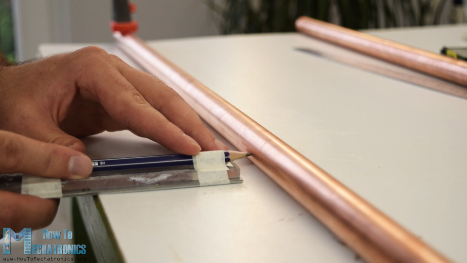
For that purpose I made a simple jig where I raised the pencil to a height of 11mm or that’s half of the pipe diameter. Then I secured the pipe on a flat surface and using the jig marked the pipe from both sides. This enables to get precisely alighted holes from both sides. So first I marked the drilling points with a sharp screw tip and then drilled them progressively using 2, 4, 6 and 8mm drill bit.
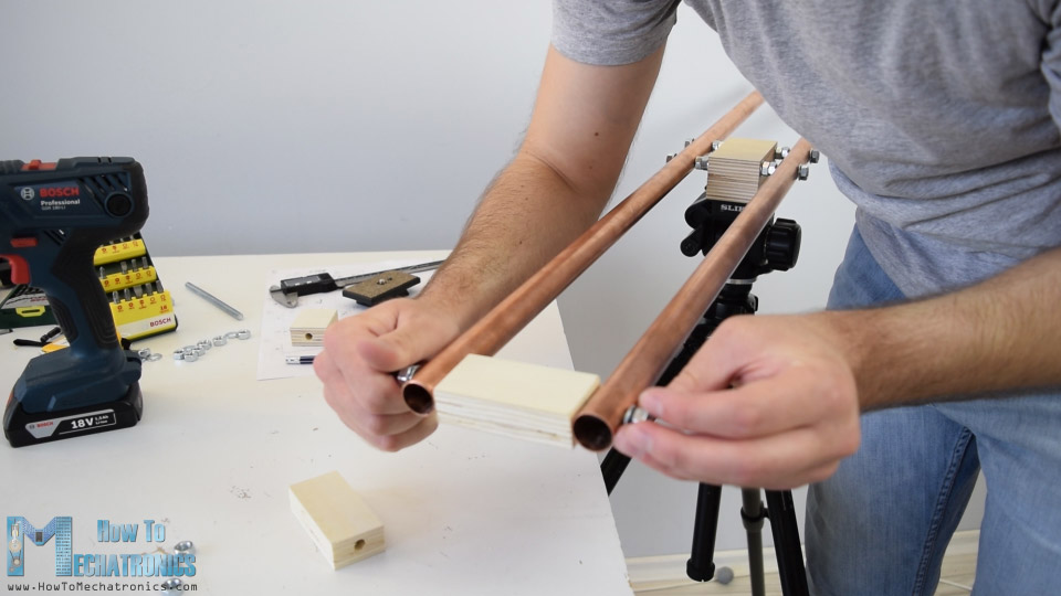
After that I inserted the rails through the threaded rods and using some washers and nuts I secured them to the slider base. In a similar way, using a piece of plywood and a threaded rod I fixed the ends of the rails.
Next is the sliding platform. Again I used a circular saw for cutting the 8mm tick MDF board to size according to the 3D model. I also made some 8mm hole for the threaded rods on which the bearing are going to be attached. For assembling the platform I used a wood glue and some screws. Using a cordless drill, first, I made pilot holes, then made the counter sinks and screwed the 3mm screws in place.
Once the panels were secured I continued with assembling the bearing system. The bearings that I’m using are 608Z with outer diameter of 22mm. Two washers and a nut between two bearings make enough distance between them thus enabling good contact with the 22mm rails.
In order to make the platform more secure when using the slider at an angle, in similar way, I inserted two more sets of bearings at the bottom side of the platform. At the end the sliding platform turned out to work perfectly.
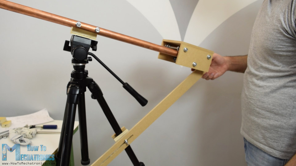
Here we can notice that now when moving the platform along the slider on my small, not heavy duty tripod, the head cannot hold the weight of the platform so I had to make a supporting arm in order to stabilize the slider. So using two pieces of wood and some nuts and bolts I made a simple clamp which can be fastened to the one of the tripod legs.
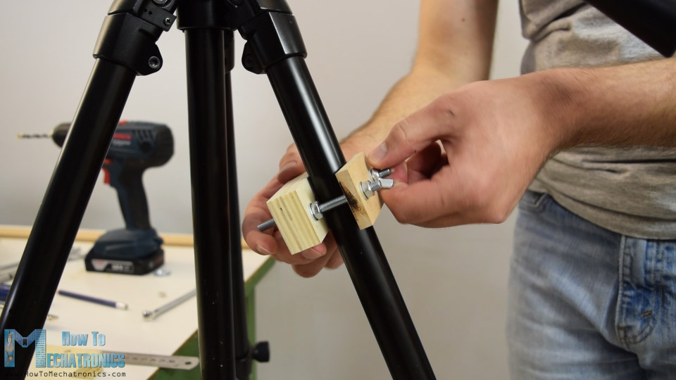
The clamp has a bolt on which the supporting arm can be fastened. Next I had to make a slot on supporting arm in order to be able to position the slider at different angle. I made the slot by simply drilling many 6mm holes close to each other, and then using a rasp made a fine straight lines. This supporting system ended up working perfectly.
I continued this build with adding legs to the slider, in case you don’t want or need to use a tripod. I made them out of 8mm MDF. Using a hand saw and a rasp I easily got the desired shape of the legs. Then using some little glue and two nuts I secured them to the ends of the slider.
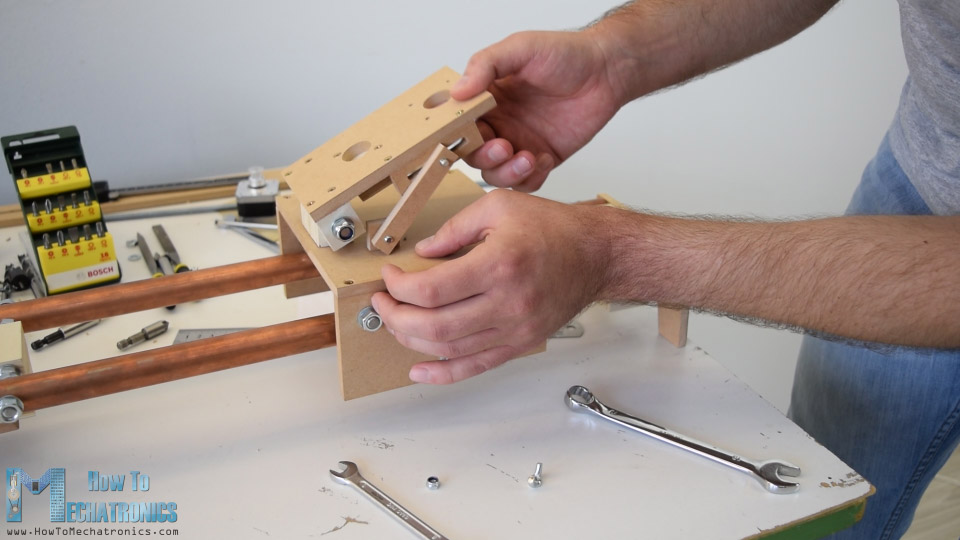
The next stage is building the pan and tilt system which will be attached on the top of the sliding platform. Using the circular saw, I cut all needed pieces, with the dimensions taken from the 3D model. I used few pieces of plywood for making the hinge mechanism of the leveling platform for the camera when the slider is set at an angle, as well as some MDF boards on which I made appropriate holes for the motor and the bearings for panning system.
I moved on with installing the stepper motor and the timing belt for the sliding platform. On one side of the platform I secured the stepper motor with a piece of MDF board and some screws and bolts. And on the other side of the slider I secured an idler pulley so now I can install the timing belt. Using two bolts and zip ties I easily secured the timing belt to the sliding platform.
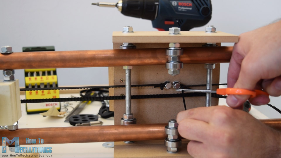
With this step the sliding mechanism was completely done.
I continued with making the upper parts of pan and tilt system. According to the 3D model, I made all appropriate holes for the stepper motor and the bearings, and glued and screwed everything together.
A friend of mine 3D printed 2 80 tooth pulleys for me. In this way I got 5 times speed reduction relative to the 16 tooth pulley attached on the stepper motor.
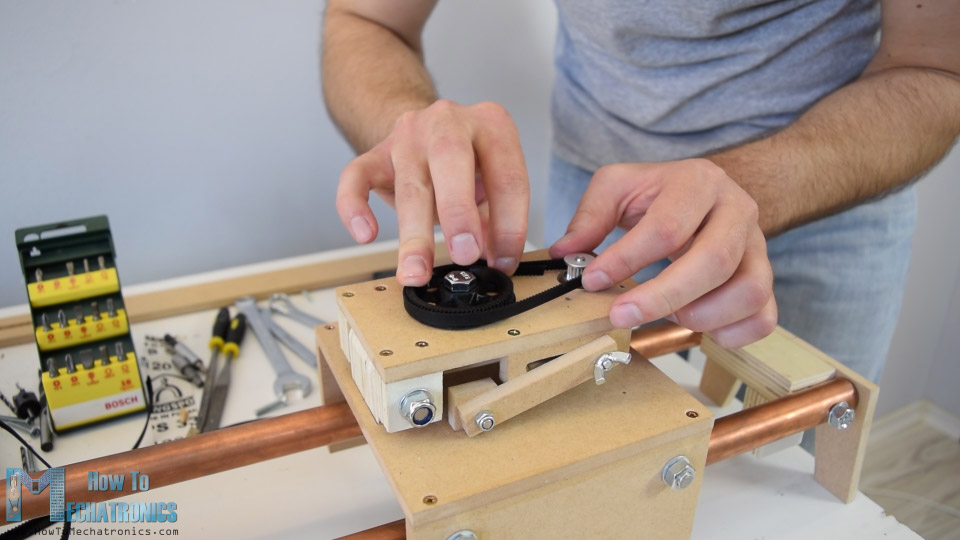
Now I needed to make a closed loop timing belt according to my setup, so I measured how much length of belt I needed, cut it and then simply glued it with a CA glue and added a piece of tape on top of it. The CA glue does a great job with rubber so the closed loop belt work without a problem.
Next I started the final assembly of the pan and tilt system. First I secured the tilt motor using some bolts and then added the two bearings in place while securing them in the slots with some epoxy. Then I secured the tilt platform on the pan platform using some 8mm bolts and at the same time I attached the 80 tooth pulley to it together with the timing belt.
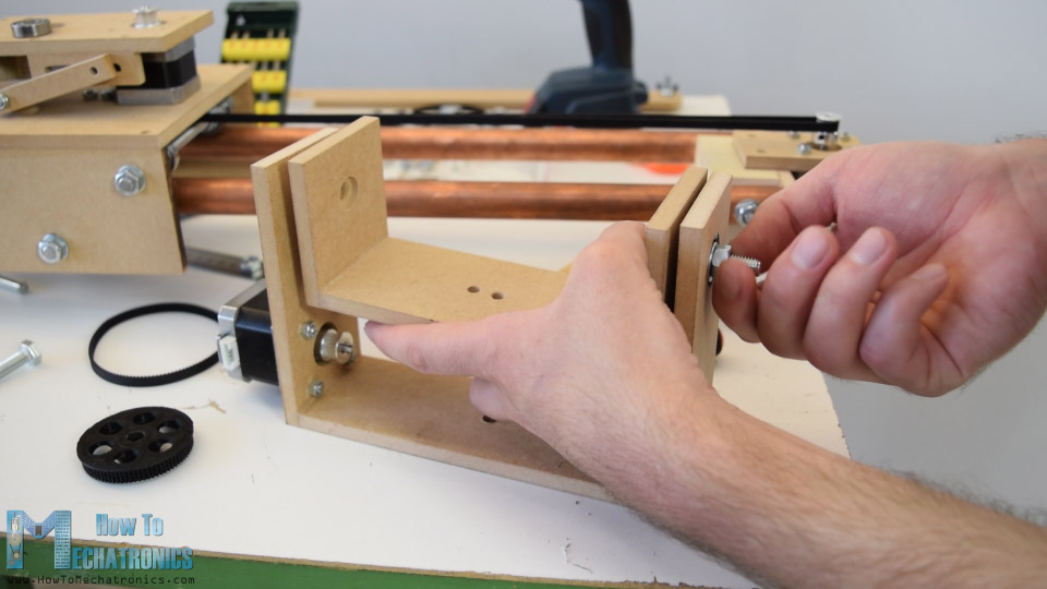
Here I noticed that the belt was a bit loose but I added a small bearing in the place where the stepper motor bolt goes to act as a belt tensioner. This thing worked out and so now the belt had enough tension to work properly.
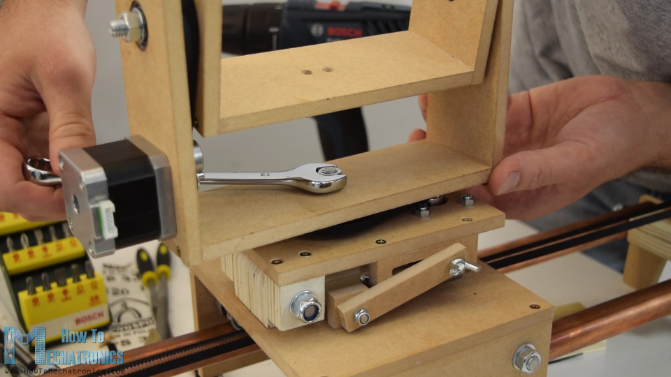
Next I secured the pan motor and added bearings the top side of the leveling platform, as well as the on bottom side. Then I inserted a bolt through them, add a thrust bearing, the 80 tooth pulley and the timing belt, and on top of them add the previously assembled tilt head. Finally I secured it using a bolt and that’s it, with this step the construction of the slider is completed.
Circuit Diagram
Ok, next comes the fun part or installing the electronics components. Here’s the circuit diagram of this DIY camera slider project.
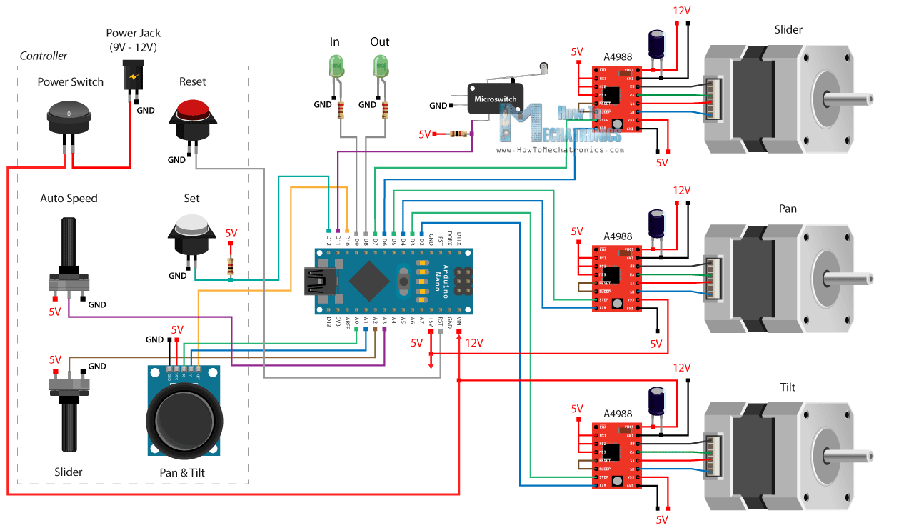
So the three NEMA 17 stepper motors are controlled via the three A4988 stepper drivers. For controlling the slider movement we use a potentiometer connected to an analog input of the Arduino, and for controlling the pan and tilt head we use a joystick module which actually consist of two potentiometers, so it is connected to two analog inputs. There’s also another potentiometer used for setting the speed of the automatic movement from the in and out positions. These in and out position are set with the help of push button. This push button has a pull up resistor and it’s connected to a digital pin of the Arduino board. There also a reset push button, a power switch and a power jack, as well as a limit switch for the slider and two LEDs for indicating the in and out status. We can power this project with either 9 or 12V.
You can get the components needed for this project from the links below:
- Stepper Motor (NEMA17)………. Amazon / Banggood / AliExpress
- A4988 Stepper Driver……………. Amazon / Banggood / AliExpress
- 12V 2A Adapter…………………..…. Amazon / Banggood / AliExpress
- Joystick ………………………………… Amazon / Banggood / AliExpress
- Power Jack…………….………….…… Amazon / Banggood / AliExpress
- Arduino Board ……………………… Amazon / Banggood / AliExpress
Disclosure: These are affiliate links. As an Amazon Associate I earn from qualifying purchases.
PCB Design
Next, according the circuit diagram I designed a custom PCB in order to keep the electronics components organized.
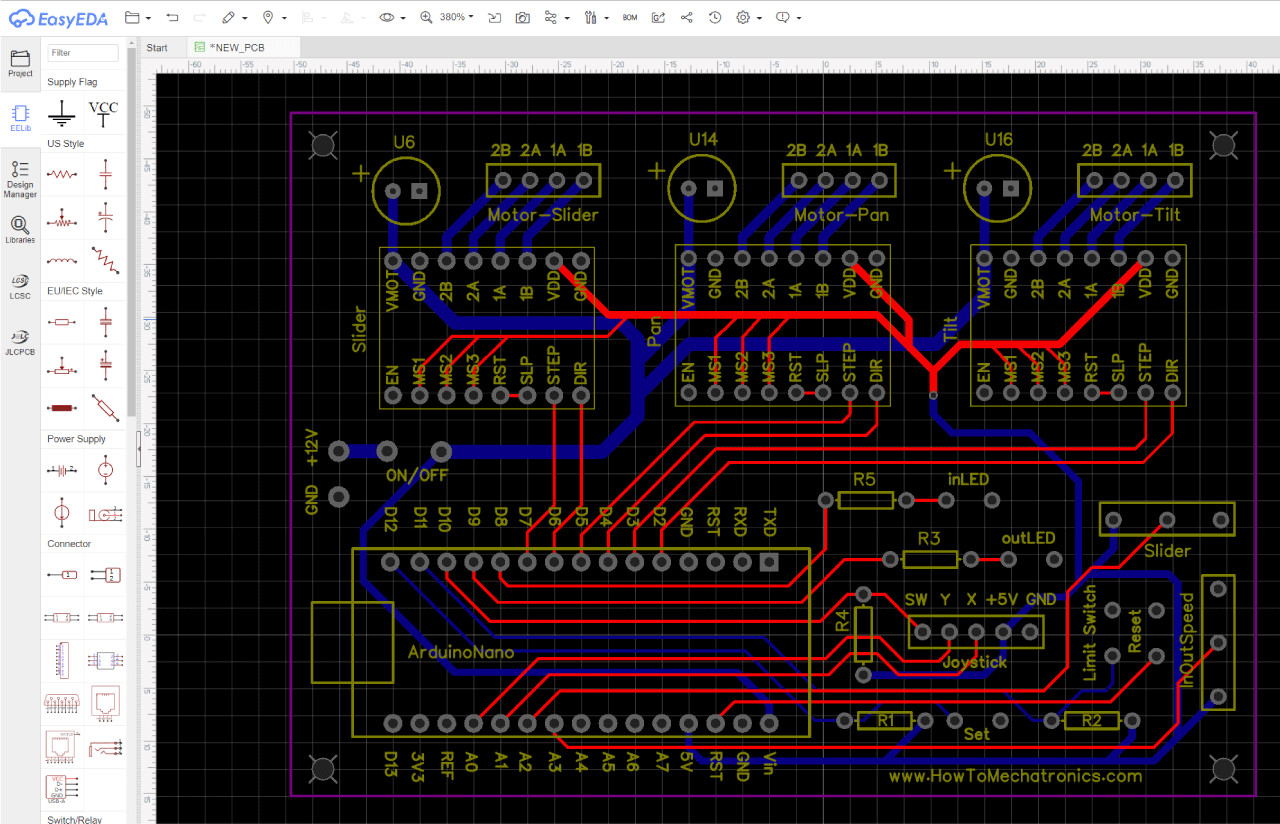
I did that using the EasyEDA free online circuit design software. The circuit had quite a few connections, so I used both the top and bottom layer and managed to get functional and good looking PCB. Once finished with this step I generated the Gerber file need for manufacturing the PCB. Then I ordered the PCB from JLCPCB, which is actually the sponsor of this tutorial.
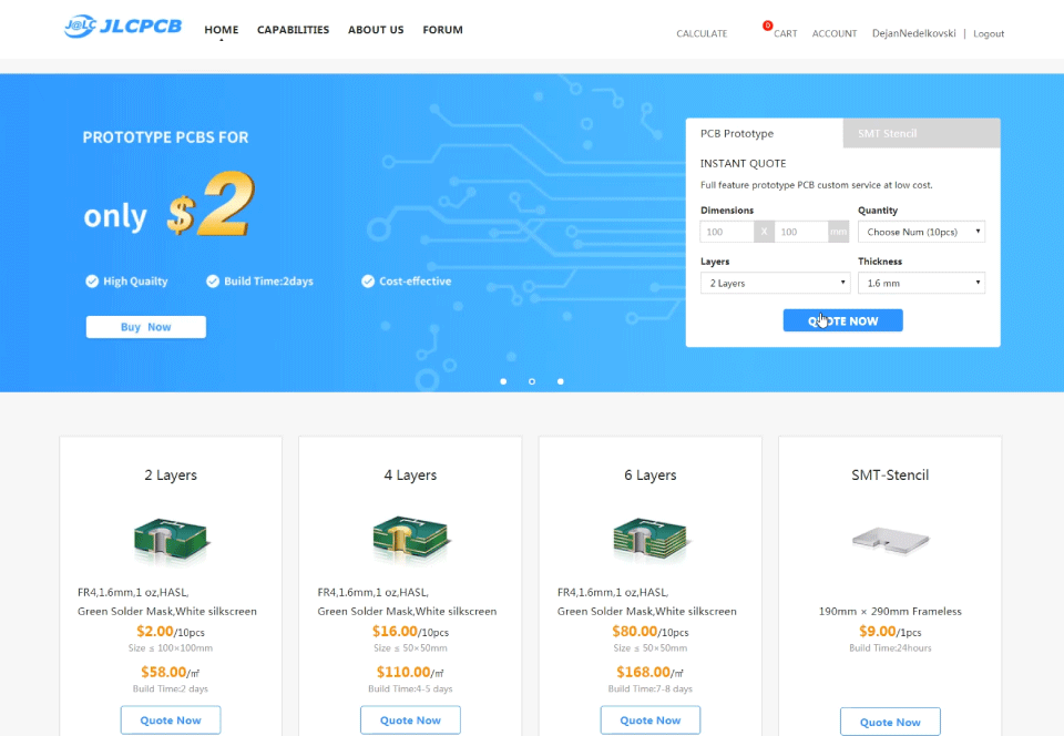
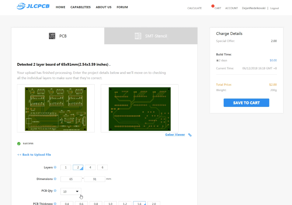
Here we can simply upload the Gerber file and once uploaded we can again review our PCB in the Gerber viewer. If everything is all right then we can go on, select the properties that we want for our PCB, and then we can order our PCB at a reasonable price. Note that if it’s your first order from JLCPCB, you can get up to 10 PCBs for only 2 dollars.
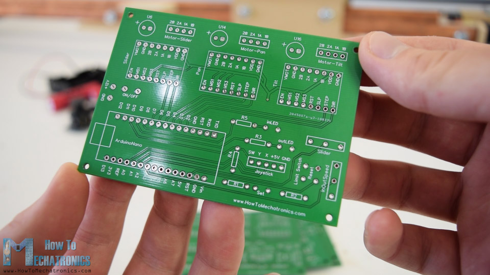
Nevertheless, after a week the PCBs have arrived. The quality of the PCBs is great and I must admit that it is quite satisfying to have your own PCB design manufactured.
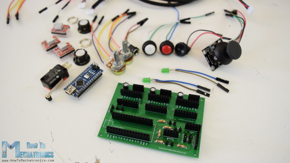
Assembling the electronics
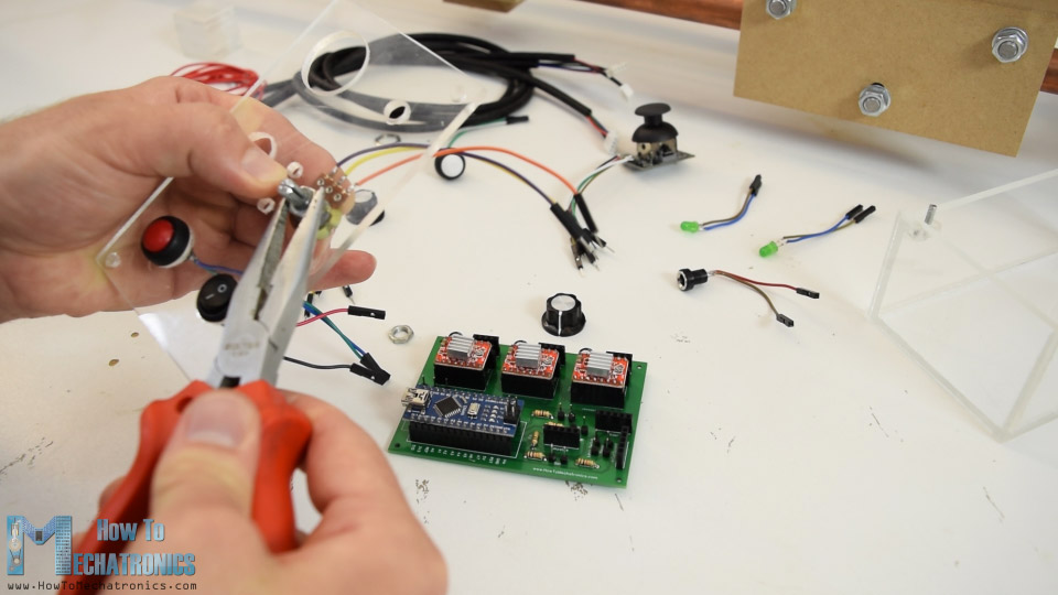
Ok, so next I moved on with assembling the electronics components. I started by soldering pin headers PCB. This enables easier connecting and disconnecting of the components when needed. I actually used pin headers for everything except the capacitors and the resistors which I soldered directly on the PCB. Therefore I continued with soldering jumper wires to all of the electronics components.
In this way I can easily mount the components on the controller case and at the same time connect them to the PCB.
As for the controller case, I decided to make it out of 4mm tick transparent acrylic because I wanted the beauty of all electronics components to be visible. I used a circular saw to cut the panels for case to size. Then using a drill and Forstner bits I made the opening on the front panel for the buttons, the potentiometers, power switch and the joystick. After that using a 5 minutes epoxy I assembled the case, and as for the top I inserted and glued two bolts through which the front panel can be inserted and secured using nuts on top of it.
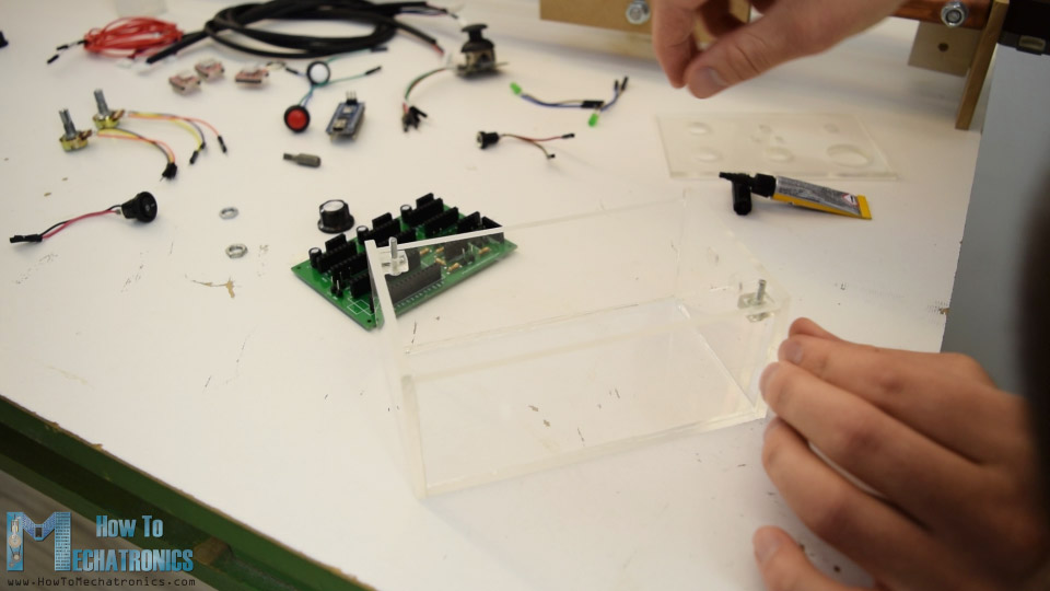
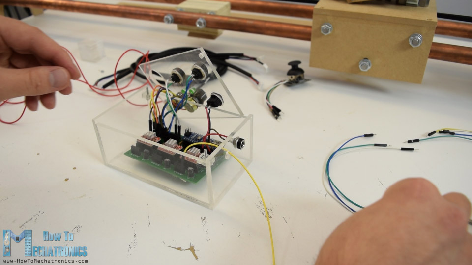
Finally I started assembling the electronics by inserting the Arduino board and the A4988 stepper drivers onto the PCB. Then I continued with inserting and securing the buttons and the other components on the front panel.
Once I had them secured I connected the components to the appropriate pin headers on the PCB. On the side panel of the case I added the power jack, and then inserted the PCB into the case. On the same panel there is also a hole through which I put jumper wires for connecting the drivers with the stepper motors, as well as the limit switch which I placed it at the end of the slider.
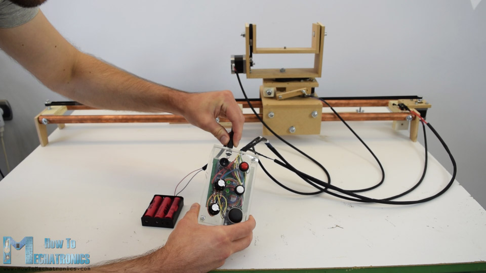
Using some heat-shrink tubing I organized the jumper wires coming out of the controller case and finally, what was left to do is to connect the controller with the three stepper motors and the limit switch.
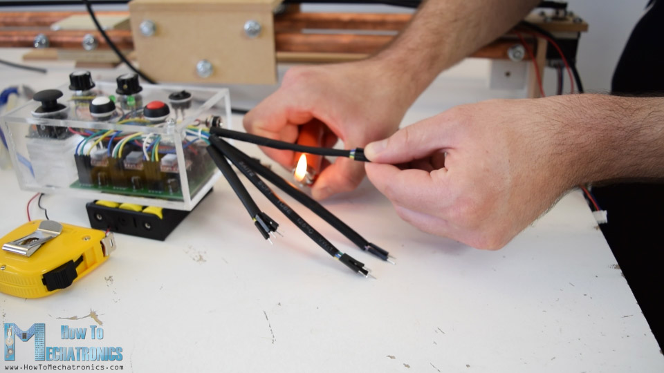
As for powering the slider I used three 3.7V Li-ion batteries connected in series producing around 11V. And that’s it, the slider is done and works perfectly.
DIY Camera Slider Arduino Code
Now what’s left in this tutorial is to take a look at the Arduino code and explain how the program works. As the code is a bit longer, for better understanding, I will post the source code of the program in sections with description for each section. And at the end of this article I will post the complete source code.
The program is based on the AccelStepper library by Mike McCauley. This is an incredible library which enables easy control of multiple stepper motors at the same time. So once we include this library and the MultiStepper.h library which is part of it, we need to define all Arduino pins that going to be used, define the instances for the steppers, as well as some variables need for the program below.
#include <AccelStepper.h>
#include <MultiStepper.h>

#define JoyX A0       // Joystick X pin
#define JoyY A1       // Joystick Y pin
#define slider A2     // Slider potentiometer
#define inOutPot A3   // In and Out speed potentiometer
#define JoySwitch 10  // Joystick switch connected
#define InOutSet 12   // Set Button
#define limitSwitch 11
#define inLED 8
#define outLED 9

// Define the stepper motors and the pins the will use
AccelStepper stepper1(1, 7, 6); // (Type:driver, STEP, DIR)
AccelStepper stepper2(1, 5, 4);
AccelStepper stepper3(1, 3, 2);

MultiStepper StepperControl;  // Create instance of MultiStepper

long gotoposition[3]; // An array to store the In or Out position for each stepper motor

int JoyXPos = 0;
int JoyYPos = 0;
int sliderPos = 0;
int currentSpeed = 100;
int inOutSpeed = 100;

int XInPoint = 0;
int YInPoint = 0;
int ZInPoint = 0;
int XOutPoint = 0;
int YOutPoint = 0;
int ZOutPoint = 0;
int InandOut = 0;Code language: PHP (php)
In the setup section we set the initial speed values for the steppers, define some pin modes, as well as add the three steppers to the multi stepper control instance called “StepperControl”. Using the while loops we move the slider to the initial position, or it moves until it press the limit switch and then it moves back 200 steps in order to release the limit switch.
void setup() {
  // Set initial seed values for the steppers
  stepper1.setMaxSpeed(3000);
  stepper1.setSpeed(200);
  stepper2.setMaxSpeed(3000);
  stepper2.setSpeed(200);
  stepper3.setMaxSpeed(3000);
  stepper3.setSpeed(200);
  pinMode(JoySwitch, INPUT_PULLUP);
  pinMode(InOutSet, INPUT_PULLUP);
  pinMode(limitSwitch, INPUT_PULLUP);
  pinMode(inLED, OUTPUT);
  pinMode(outLED, OUTPUT);

  // Create instances for MultiStepper - Adding the 3 steppers to the StepperControl instance for multi control
  StepperControl.addStepper(stepper1);
  StepperControl.addStepper(stepper2);
  StepperControl.addStepper(stepper3);

  // Move the slider to the initial position - homing
  while (digitalRead(limitSwitch) != 0) {
    stepper1.setSpeed(3000);
    stepper1.runSpeed();
    stepper1.setCurrentPosition(0); // When limit switch pressed set position to 0 steps
  }
  delay(20);
  // Move 200 steps back from the limit switch
  while (stepper1.currentPosition() != -200) {
    stepper1.setSpeed(-3000);
    stepper1.run();
  }
}Code language: JavaScript (javascript)
In the loop section we start by checking whether the slider has reached the limit positions, or that’s the limit switch or 80cm on the other side of it.
// Limiting the movement - Do nothing if limit switch pressed or distance traveled in other direction greater then 80cm
  while (digitalRead(limitSwitch) == 0 || stepper1.currentPosition() < -64800) {}Code language: JavaScript (javascript)
With the next if statement we increase the Pan and Tilt speeds with each press of the joystick switch.
// If Joystick pressed increase the Pan and Tilt speeds
  if (digitalRead(JoySwitch) == 0) {
    currentSpeed = currentSpeed + 50;
    delay(200);
  }Code language: JavaScript (javascript)
Then we check whether we have pushed the Set button, which is used for setting the IN and OUT positions. With the first push of the button we store the IN positions of stepper motors and also light up the IN LED.
switch (InandOut) {
      case 0:   // Set IN position
        InandOut = 1;
        XInPoint = stepper1.currentPosition(); // Set the IN position for steppers 1
        YInPoint = stepper2.currentPosition(); // Set the IN position for steppers 2
        ZInPoint = stepper3.currentPosition(); // Set the IN position for steppers 3
        digitalWrite(inLED, HIGH); // Light up inLed
        break;Code language: JavaScript (javascript)
In the same way, with the second push we store the OUT positions and light up the OUT LED.
case 1: // Set OUT position
        InandOut = 2;
        XOutPoint = stepper1.currentPosition(); //  Set the OUT Points for both steppers
        YOutPoint = stepper2.currentPosition();
        ZOutPoint = stepper3.currentPosition();
        digitalWrite(outLED, HIGH);
        break;Code language: JavaScript (javascript)
Then with the next push of the button, we read the value of the auto speed potentiometer which is use to set the maximum speed of the motors. Also we put the IN positions into the “gotoposition” array which is used in the moveTo() function which calculates the required speed for all steppers separately. Then using the runSpeedToPosition() function the slider automatic moves to In position.
case 2: // Move to IN position / go to case 3
        InandOut = 3;
        inOutSpeed = analogRead(inOutPot); // Auto speed potentiometer
        // Place the IN position into the Array
        gotoposition[0] = XInPoint;
        gotoposition[1] = YInPoint;
        gotoposition[2] = ZInPoint;
        stepper1.setMaxSpeed(inOutSpeed);
        stepper2.setMaxSpeed(inOutSpeed);
        stepper3.setMaxSpeed(inOutSpeed);
        StepperControl.moveTo(gotoposition); // Calculates the required speed for all motors
        StepperControl.runSpeedToPosition(); // Blocks until all steppers are in position
        delay(200);
        break;Code language: JavaScript (javascript)
In exactly the same way, in case number 3 or with another push of the button, we move the slider to the OUT position.
case 3: // Move to OUT position / go back to case 2
        InandOut = 2;
        inOutSpeed = analogRead(inOutPot);
        // Place the OUT position into the Array
        gotoposition[0] = XOutPoint;
        gotoposition[1] = YOutPoint;
        gotoposition[2] = ZOutPoint;
        stepper1.setMaxSpeed(inOutSpeed);
        stepper2.setMaxSpeed(inOutSpeed);
        stepper3.setMaxSpeed(inOutSpeed);
        StepperControl.moveTo(gotoposition); // Calculates the required speed for all motors
        StepperControl.runSpeedToPosition(); // Blocks until all are in position
        delay(200);
        break;Code language: JavaScript (javascript)
In case we hold the Set button pushed for longer than half a second the 4th case statement will be executed, which resets the IN and OUT position so we can set new ones.
Next is the joystick Pan and Tilt control. The analog value we are getting from the joystick is from 0 to 1024, or when it rests in the middle the values is around 500. So if we move the joystick to left and the analog value is greater than 600, we will set the speed of the particular motor to positive, and opposite, of we move the joystick right, we will set the speed of the motor to negative, which means it will rotate the opposite way.
// Joystick X - Pan movement
  JoyXPos = analogRead(JoyX);
  // if Joystick is moved left, move stepper 2 or pan to left
  if (JoyXPos > 600) {
    stepper2.setSpeed(currentSpeed);
  }
  // if Joystick is moved right, move stepper 2 or pan to right
  else if (JoyXPos < 400) {
    stepper2.setSpeed(-currentSpeed);
  }
  // if Joystick stays in middle, no movement
  else {
    stepper2.setSpeed(0);
  }Code language: JavaScript (javascript)
In case it stays in the middle, the speed is set to 0. This method is used for both axis of the joystick as well as the slider potentiometer. Actually, in the case of the potentiometer we use its analog value to also increase the speed of the motor as we further turn the potentiometer.
// Slider potentiometer
  sliderPos = analogRead(slider);
  // If potentiometer is turned left, move slider left
  if (sliderPos > 600) {
    sliderPos = map(sliderPos, 600, 1024, 0, 3000);
    stepper1.setSpeed(sliderPos); // Increase speed as turning
  }
  // If potentiometer is turned right, move slider right
  else if (sliderPos < 400 ) {
    sliderPos = map(sliderPos, 400, 0, 0, 3000);
    stepper1.setSpeed(-sliderPos); // Increase speed as turning
  }
  // If potentiometer in middle, no movement
  else {
    stepper1.setSpeed(0);
  }Code language: JavaScript (javascript)
Lastly, we call the runSpeed() functions for each of the three stepper motors and that executes the above commands, or rotates the motors appropriately.
// Execute the above commands - run the stepper motors
  stepper1.runSpeed();
  stepper2.runSpeed();
  stepper3.runSpeed();Code language: JavaScript (javascript)
Here’s the complete source code:
/*
  DIY Camera Slider with Pan and Tilt Head
  by Dejan Nedelkovski
  www.HowToMechatronics.com

  Library - AccelStepper by Mike McCauley:
  http://www.airspayce.com/mikem/arduino/AccelStepper/index.html

*/

#include <AccelStepper.h>
#include <MultiStepper.h>

#define JoyX A0       // Joystick X pin
#define JoyY A1       // Joystick Y pin
#define slider A2     // Slider potentiometer
#define inOutPot A3   // In and Out speed potentiometer
#define JoySwitch 10  // Joystick switch connected
#define InOutSet 12   // Set Button
#define limitSwitch 11
#define inLED 8
#define outLED 9

// Define the stepper motors and the pins the will use
AccelStepper stepper1(1, 7, 6); // (Type:driver, STEP, DIR)
AccelStepper stepper2(1, 5, 4);
AccelStepper stepper3(1, 3, 2);

MultiStepper StepperControl;  // Create instance of MultiStepper

long gotoposition[3]; // An array to store the In or Out position for each stepper motor

int JoyXPos = 0;
int JoyYPos = 0;
int sliderPos = 0;
int currentSpeed = 100;
int inOutSpeed = 100;

int XInPoint = 0;
int YInPoint = 0;
int ZInPoint = 0;
int XOutPoint = 0;
int YOutPoint = 0;
int ZOutPoint = 0;
int InandOut = 0;

void setup() {
  // Set initial seed values for the steppers
  stepper1.setMaxSpeed(3000);
  stepper1.setSpeed(200);
  stepper2.setMaxSpeed(3000);
  stepper2.setSpeed(200);
  stepper3.setMaxSpeed(3000);
  stepper3.setSpeed(200);
  pinMode(JoySwitch, INPUT_PULLUP);
  pinMode(InOutSet, INPUT_PULLUP);
  pinMode(limitSwitch, INPUT_PULLUP);
  pinMode(inLED, OUTPUT);
  pinMode(outLED, OUTPUT);

  // Create instances for MultiStepper - Adding the 3 steppers to the StepperControl instance for multi control
  StepperControl.addStepper(stepper1);
  StepperControl.addStepper(stepper2);
  StepperControl.addStepper(stepper3);

  // Move the slider to the initial position - homing
  while (digitalRead(limitSwitch) != 0) {
    stepper1.setSpeed(3000);
    stepper1.runSpeed();
    stepper1.setCurrentPosition(0); // When limit switch pressed set position to 0 steps
  }
  delay(20);
  // Move 200 steps back from the limit switch
  while (stepper1.currentPosition() != -200) {
    stepper1.setSpeed(-3000);
    stepper1.run();
  }

}

void loop() {
  // Limiting the movement - Do nothing if limit switch pressed or distance traveled in other direction greater then 80cm
  while (digitalRead(limitSwitch) == 0 || stepper1.currentPosition() < -64800) {}

  // If Joystick pressed increase the Pan and Tilt speeds
  if (digitalRead(JoySwitch) == 0) {
    currentSpeed = currentSpeed + 50;
    delay(200);
  }
  // If Set button is pressed - toggle between the switch cases
  if (digitalRead(InOutSet) == 0) {
    delay(500);
    // If we hold set button pressed longer then half a second, reset the in and out positions
    if (digitalRead(InOutSet) == 0) {
      InandOut = 4;
    }
    switch (InandOut) {
      case 0:   // Set IN position
        InandOut = 1;
        XInPoint = stepper1.currentPosition(); // Set the IN position for steppers 1
        YInPoint = stepper2.currentPosition(); // Set the IN position for steppers 2
        ZInPoint = stepper3.currentPosition(); // Set the IN position for steppers 3
        digitalWrite(inLED, HIGH); // Light up inLed
        break;

      case 1: // Set OUT position
        InandOut = 2;
        XOutPoint = stepper1.currentPosition(); //  Set the OUT Points for both steppers
        YOutPoint = stepper2.currentPosition();
        ZOutPoint = stepper3.currentPosition();
        digitalWrite(outLED, HIGH);
        break;

      case 2: // Move to IN position / go to case 3
        InandOut = 3;
        inOutSpeed = analogRead(inOutPot); // Auto speed potentiometer
        // Place the IN position into the Array
        gotoposition[0] = XInPoint;
        gotoposition[1] = YInPoint;
        gotoposition[2] = ZInPoint;
        stepper1.setMaxSpeed(inOutSpeed);
        stepper2.setMaxSpeed(inOutSpeed);
        stepper3.setMaxSpeed(inOutSpeed);
        StepperControl.moveTo(gotoposition); // Calculates the required speed for all motors
        StepperControl.runSpeedToPosition(); // Blocks until all steppers are in position
        delay(200);
        break;

      case 3: // Move to OUT position / go back to case 2
        InandOut = 2;
        inOutSpeed = analogRead(inOutPot);
        // Place the OUT position into the Array
        gotoposition[0] = XOutPoint;
        gotoposition[1] = YOutPoint;
        gotoposition[2] = ZOutPoint;
        stepper1.setMaxSpeed(inOutSpeed);
        stepper2.setMaxSpeed(inOutSpeed);
        stepper3.setMaxSpeed(inOutSpeed);
        StepperControl.moveTo(gotoposition); // Calculates the required speed for all motors
        StepperControl.runSpeedToPosition(); // Blocks until all are in position
        delay(200);
        break;

      case 4: // If Set button is held longer then half a second go back to case 0
        InandOut = 0;
        digitalWrite(inLED, LOW);
        digitalWrite(outLED, LOW);
        delay(1000);
        break;
    }
  }

  // Joystick X - Pan movement
  JoyXPos = analogRead(JoyX);
  // if Joystick is moved left, move stepper 2 or pan to left
  if (JoyXPos > 600) {
    stepper2.setSpeed(currentSpeed);
  }
  // if Joystick is moved right, move stepper 2 or pan to right
  else if (JoyXPos < 400) {
    stepper2.setSpeed(-currentSpeed);
  }
  // if Joystick stays in middle, no movement
  else {
    stepper2.setSpeed(0);
  }

  //Joystick Y - Tilt movement
  JoyYPos = analogRead(JoyY);
  if (JoyYPos > 600) {
    stepper3.setSpeed(currentSpeed);
  }
  else if (JoyYPos < 400) {
    stepper3.setSpeed(-currentSpeed);
  }
  else {
    stepper3.setSpeed(0);
  }

  // Slider potentiometer
  sliderPos = analogRead(slider);
  // If potentiometer is turned left, move slider left
  if (sliderPos > 600) {
    sliderPos = map(sliderPos, 600, 1024, 0, 3000);
    stepper1.setSpeed(sliderPos); // Increase speed as turning
  }
  // If potentiometer is turned right, move slider right
  else if (sliderPos < 400 ) {
    sliderPos = map(sliderPos, 400, 0, 0, 3000);
    stepper1.setSpeed(-sliderPos); // Increase speed as turning
  }
  // If potentiometer in middle, no movement
  else {
    stepper1.setSpeed(0);
  }
  // Execute the above commands - run the stepper motors
  stepper1.runSpeed();
  stepper2.runSpeed();
  stepper3.runSpeed();
}Code language: PHP (php)
So that would be all, I hope you enjoyed this Arduino project and learned something new. Feel free to ask any question in the comments section below and check my Arduino Projects Collection.
I finally got it working and i like it a lot but with one caveat; there’s no acceleration or deceleration of the movement so it just jarrs to a stop at the end of the cycle and shakes the whole assembly which looks very bad on film. Any chance you have some code that would allow it to “ease in and out” of the movements? Thanks.
Hey, nice to hear you made it. Well the AccelStepper library has acceleration and deceleration capabilities but only when moving a single motor at a time. When using the MultiStepper library which is needed for the more complex movements when the 2 or 3 motors move at the same time, then acceleration and deceleration is not available.
There might be another way to achieve this, maybe another library but at this time I don’t know and cannot provide any help with it.
Hi Dejan,
i use the TMC Steppers with 256 microstepping. How can i speed up the slider, wich settings i have to change in the code?
Thank you
OK i found the problem. I don’t connect GND on the Arduino. Now it works.
I’m trying to replicate the control system. I have already scrapped three arduino. Somehow the control does what it wants with me. Once a motor moves, the next time i switch it on you can turn it freely on the shaft. I despair 🙁
Does the aduiono clone works also or do i need original one?
Hey, you can use clones, of course they work. Do you use the PCB from JLCPCB or you are making the connections on a breadboard or something? I mean, there can be many things that could go wrong. Try to provide some additional info so we can try to figure it out what is going on.
Hi Dejan, thank you for reply. I make my own PCB by milling. All on one side. Find my layout on EasyEDA
https://easyeda.com/editor#id=|cbc850db453b41ad8cbc4e4d47ec1a03
The problem actually is that i grill every A4988 i insert in the PCB.
May i not put the circuit into operation without motors? I want to check the Vref. I put the driver in an other test circuit to adjust the vref to 0,4V.
When i put the driver in the sliders pcb the vref rise up to 0,7V without motor pluged in.
After this, when i try the driver in my test circuit, i must realised that it is broken.
🙁 At this moment i grillt about 10 drivers 🙁
Hi again
I have found out that it is the arduino code that is to slow for my arduino board, I can see that the motors are moving very very slow, I have tried many things but when i made a loop in the program like this:
pan:
stepper2.setSpeed(-3000);
stepper2.runSpeed();
goto pan;
Then it moves fast in that direction.
I have bought the Arduino Nano at Banggood.com, but it is obviously too slow.
Br Steen
Well yeah, the code is not really optimized. Try to remove all Serial.print() functions from the code, the slow down the code significantly.
I have the same problem with speed. Thought of trying with a Teensy to see if that solves the problem.
Steen, Have you found a solution?
Hi
It is a very fine camera slider You have build!
I have also build one, but i have a problem. When the slider starts up it move to one side until limit switch is activated and then it moves 200 step the other way, thats good, but after that nothing happens. i can’t tilt, pan or moving slider. I have now tryid with 2 differnt pcb, motor driver, motor, joystick, arduino board ??
Can it be the Arduino board it is not a original one.
Can it be the size of the potentiometer og resistors?
Please help.
Hey, thanks! Several people have already reported this similar problem. I have already doubled check the current PCB and everything looks fine to me. Maybe it is something with the code but I really cannot say anything specific.
Hopefully someone who had similar problem and managed to solve it, will tell us about it. At this moment I really cannot give you any advice, sorry about that.
Hello,
Thank you for this great tutorial.
I’m a newbie and I have a question :
if I use 3 motor (12V, 2A), do I need a power source 12V 6A ; or 12V 2A ?
I don’t know if I have to add intensity.
Thank you for your help.
Hey, yes that’s right. However, these stepper motors are rated 2A but they usually consume around 1A to 1.5A. Also the driver has a knob though which you can control the current limit, or you can also set the motor to consume even less, for example 0.5A or so.
Hello!
Your project is amazing, thank you so much for the very detailed work. I built my version of it and i’m trying to adapt it for my needs. im great with all the mechanical and electrical and BASIC coding but i can’t seem to do what i want. I would like to raise the slider speed by a lot since im using it over a great distance and also i would like to limit the rotation of the pan to 360 because i don’t want my cables to tangle around the axel. can you help me with that? or maybe point me the right direction.
Hey, thank you! Well you could increase the speed by increasing the value for the speed with the setSpeed() function. Though I have found that sometimes setting higher value would mean nothing if the Arduino is not able to execute the steps that fast. I guess the problem is that the code is not really that good or optimized. In such a case, you could try lower stepping resolution, that will increase the speed but you would lose the smoothness.
As for limiting the pan rotation, maybe you could use the currentPosition() function through which you can get how many steps the motors have made in a particular direction, and using a simple “if” statement confine the movement of the pan if the value is greater then the number of steps that make around 180 degrees in the particular direction, or something like that.
if we are using set position button
is it real that when we pressed the initial pos, then we need to move the camera manually using our hand to reach end pos? then after that we pressed the set button again to set the end point and the camera slider will go back and forth
Hi !
Great project ! I was amazed by the idea of doing it myself.
However, after recieving the PCB, it looks like it just doesnt work. Wired everything correctly I think. I have power on both controller & motor inputs on the A4899 but the whole thing doesn’t behave as expected.
What is working : When powered up, the slide motor keeps running. Reset button will work
What is not working : everything else. Tuning potentiometers won’t affect speed. The second button won’t do anything. The joystick won’t have the other motors working and clicking the stop sensor won’t stop the motor.
Is that a problem that someone ever had and solved to your knowledge ?
Tried using different arduinos no improvement 🙁
Hey, thanks! Somebody else above has reported this same behavior. I took a look at the PCB and I can see that everything looks good. It might be something wrong with the code. The thing that the slide motor runs when powered up, is that it is looking for it’s home position, and that happens when the limit switch button is pressed (take a look at the Setup section of the Arduino code, the while loops waits until the limit switch is pressed). So make sure connected the limit switch properly, try the other way NC or NO.
Hi,
Only one question…i am new to Projects like Yours…do i have to connect all gnd s, i mean the grounds from the Parts to finally End in „-„?
Well yeah, all GNDs should be connected together.
Thank you for fast response.
Hello Dejan, this is a very interesting project thank you for the work you have done publishing it.
I am an “old” newbie, trying to improve my skill.
I have reached a point where I have carefully assembled your PCB, which was turned around very quickly, the included library file and your sketch have uploaded ok but when I apply the power the red led on the Nano lights, but the Slider motor spins continuously and the other two appear to be locked. Touching the limit SW or any button does not alter anything.
Please is it possible to suggest where and how to start trouble shooting.
Many thanks for any help.
William.
Hey, thanks! Well you could start with checking whether the Slider potentiometer is connected and working properly. If the Slider motor is spinning continuously it means you are getting a wrong value from the potentiometer (when the potentiometer is set in the middle you should receive value around 512, you can check what value you are getting using the Serial.println function and print the analog input on the serial monitor). The other two motors with have the same problem, check whether you are getting correct values from the joystick, whether it’s connected properly.
hi dejan,
I am make your slider project. it works well but the vibration in the motors shakes the camera. motors do not run smoothly. They work like it’s not in 1/16 step. I used your pcb and did everything properly. I updated the potentiometer and joystick values I used. Also the speed of these motors is very slow? With a value of 3000, he makes a lap in 6 seconds.
Hey, well make sure it’s really set to 1/16 step or also you could try to use DRV8825 drivers. Also the problem might be that you program is slow, I mean in case you have added some code in the program. So the Arduino is not able to go fast through the code, and so the stepper makes the steps slower and that’s why buzzing occurs. Try to reduce the code, also you could try to use higher baud rate maybe, if using serial port for printing something, or if there are some Serial.println() lines make sure you remove/ comment them because they are slow functions.
Hey, can I use TMC2208 instead of A4988?
Everything is ok.
But when I replace one A4988 with a TMC2208 the Motor doesnt work then…
What is the Problem?
Hello,
nice desing. I’ve ordered all parts. But I use the DRV8825 drivers instead of the one you listed. Those should work but when I connect everything like in the picture provided, the motors sometimes work but the driver get extremlely hot and then die.
I tried different connection methodes but nothing will work. Do you have maybe an idea?
Thanks
Hey, try to limit the current the drivers can use with the small potentiometer on top of the drivers. You could limit it to around 0.5/0.6A so they won’t overheat. The DRV8825 drivers should work the same as the A4988 drivers. Just make sure you match the step resolution by connecting the appropriate resolution selecting pins.
Can i make the project without the pcb or it will affect the code and the project
Sure, you can make the project without the PCB. If you connect everything as described in the circuit diagram, it won’t affect the code and everything will work exactly the same.
the potentiometer is a 1K Ohm?
Hi,
great Slider!!!
I have only 4,7K Pots… is it ok???
Thanks!
Hey, thanks! Yes sure, 4.7k pots are ok.
Thank you for this beautifully described and presented project which I am about to start on. Before I start, I was looking for a list of components. Everything is pretty obvious (thank you!) except I cannot find values for the *resistors* (from the video looks like 10k ohms 5%) and *capacitors* – have I missed something?
I’d also like to check if the pcb file online is the latest version.
Very many thanks for this super project!
Thank you! Yes the resistors can be 10K for the pull-up resistors, while 220 or 330 ohms for the LEDs. The capacitors can be anything from 10 to 100uF (16-36V).
The PCB is the latest version.
Have fun building it!
The resistors is 1/4 watt or 1 watt?
Thank you
They are 1/4 watts.
Hi. It is a very interesting project. I tried to do it but when I use the pan and tilt with the joystick at very slow speeds the movement is not fluid. Do you know how I can solve it?.
Thanks greetings.
Hey, make sure you have selected the highest stepping resolution of 1/16 or 1/32 if using the DRV8825 stepper driver.
Hey, how do i set the resolution? :/
Hey, the resolution of the stepper driver is set to 16th step resolution. The three MS pins are already connected on the PCB to 5 volts, so with this PCB you cannot select different resolution.
Hello Dejan, would the slider setup also work with alu or stainless steel tubes? And what if 22mm is unavailable? Is 20 or 25mm workable?
kind regards
Geert
Hello,
An excellent project!
I’m curious, how silent are the motors at work?
If I’ll use this to film an interview, would the noise be haired?
Thanks in advance.
Hey thanks! The motors are noisy, so it they won’t be suitable for such an use.
If you use the TMC2208 drivers instead of the 4988, the motors will be super silent (yes I saw the date)
Hello Dejan, Amazing stuff you got there.
Ive been searching for a month now on how to adapt such system so that I can control it with bluetooth. could you please point me in the right direction ?
Thanks! Well well the code working principle would be the same, just the input variables would need to come from the Bluetooth module. You can see such examples on my other Bluetooth related tutorials, for example the Wireless controlled robot car project. You see there, we send commands from a smartphone, via the Bluetooth, and then we can use those commands to do whatever we want with the Arduino.
Hello Dejan, a big “Bravo” for sharing this.
Do you think the Nema 17 high torque 60Ncm can deal with à 3kg camera in pan & tilt ? Even if the camera is really well equilibrated to avoid excessive strength when rotating and maintaining ?
Thank-you.
Thanks! Well 60Ncm means it lift around 6kg at 1 cm distance. But then we also have speed reduction and that increase the torque. So I would say it should be able to deal with that 3kg camera.
Dejan,
Great set of tutorials. Over the holiday I decided to experiment with the camera slider. I made a DIY slider a few years ago and always wanted to add some motorized movement. I had a few mishaps along the way, like installing one of the the stepper drivers backwards and burning up the driver as well as the Arduino Nano. Now I have everything working…sort of. I adjusted the overall distance of the slider after hitting the limit switch to 96cm ” stepper1.currentPosition() 50cm from the limit switch position AND/OR an “OUT” >15cm from the “IN” the slider somehow resets the values and moves back towards the limit switch. Most times hitting it without stopping.
When I autorun shorter distances from the limit switch AND <15cm between "IN"/"OUT" the slider works great. ie. short camera moves
It's like there is a limit on the currentPosition or gotoposition array values when it calculates the motor steps.
Hi Dejan,
thank you so much for sharing this fantastic project!
I am currently adapting it for my needs and was wondering how you determined the needed stepper torque. I’d like to use lighter NEMA17 stepper motors for pan and tilt, because they basically only rotate the camera around its own center axis and the big 80 teeth cogs decrease the speed by factor 4. So maybe 26 N/cm would be enough?
Could it be calculated this way?
(26 N/cm holding torque * 100) / 0,8 mm pulley radius = 3250g
best, Philip
Thanks! Well yeah, your calculation seems good.
Hello Dejan,
Also, what values for the resistors and capacitors did you use? I see conflicting values in the comments…
kind regards
Geert
Hello Dejan,
What ohm range did you use for the potentiometers?
kind regards
Geert
Hey,
I turn on the power to the board, the motors are “twitching”. I pressed the set/reset buttons; the motors will stop, but start “twitching” again. I even reprogrammed the Nano and it successfully upload, checked soldering points on the board, stepper motors are corrected (nothing is overheating), and checked all connections to the board and everything is good. What could be causing the motors to “twitched?”
Thank you.
Hey, did you check the current limit on your drivers? Also you might have connected wrongly the four wires of the motors to the drivers.
OK, here’s what I did:
-Tested each driver individually; all did the same “twitching” thing.
-Replaced all the resistors with the ones you used in the video (was using 5 band resistors with the wrong ohms)
-Checked all soldering points for shorts; no damage.
-Checked all the switches and buttons; all have continuity.
-Replaced the joystick (ordered 5 in all); same “twitching”
-Checked the polarity of the capacitors (100uf/16v); all corrected.
-Even reprogrammed the Nano; Done uploading.
-Checked the pots (one is 100K for slider/one is 250K for Autospeed); when I turn the Slider pot, the motor responds but does turn. (Note: I have not assemble the motors to the Slider, so they are just sitting on my workbench “twitching” as I turn the Slider pot with no rotation).
-Mircoswitch works perfectly
-Used different motors and all three did the same thing.
On your diagram, I’m only seeing 4 resistors, but on the PCB there is five (R4 is the one I don’t know what value of resistor goes there so I put a 1K ohm)
I’m stomped on this, Dejan. If you have an email, I can take pictures (or even video) of what I’m doing. I guessing maybe its the wrong size motors.
Thanks.
Update. Sorry, the motor DOESN’T turn when the Slider pot is used.
Hi,
Can we add a few more positions.
Hey, sure that’s possible, but that function needs to be added to the code.
Hello Dejan,
Like the project a lot, fantastic job you did, gathering stuff to build it myself now.
Just one question, do you think it’s possible to add an LCD (20×4 for instance) to see what settings you are applying to the stepper motors? If possible, how would you do it?
kind regards,
Geert
Hey Geert, thanks!
Well yes it’s possible to add LCD and make some kind of menu system to choose settings and enter values from the LCD using potentiometers and buttons. But of course, it all has to be programmed appropriately. I’m not sure if I can give you any tips as it requires quite some coding.
Hey dejan,
I want to make this for my science project at school, could you please share the 3d file for the wheel?
Thanks for the idea.
Thanks in advance for the response.
There is a link to it in the article above, at the 3D model section.
Excellent project. I’ll try it like a gift to my girlfriend in her birthday, could you help me with the specifications of the motors… I would like make it with a wireless control.
Thanks! The motors are NEMA 17 stepper motors controlled with the A4988 drivers. All details are explained above in the Arduino and in the video.
Great project. Downloaded the Solidworks files but I don’t see the larger gears. Not in the folder and their errored and missing in Solidworks itself.
Can you upload the complete file or at least the gear you had 3d printed so we have the same ratio used in your code?
Thanks! I added a link to the GT2 Pulley.
Hello, This is an excellent project, I am compiling a list of parts, but I am unable to locate the link to the 80 tooth pulley, I am using Google Chrome, not sure where the link is.
Is it possible to help please.
What make of joystick did you use the few I have looked at have a very short spindle.
Many thanks William.
Hey William, thank you! The link for the tooth pulley is located right below the 3D model download files. I also updated the part list and added the joystick that I used.
Hey Dejan, Hope you are well genius!
Brilliant work. Im trying to follow this. Have no idea about any of this. I am pure winging it. A few questions:
What is connected with the a4988 with the 12v power supply?
can i use other motor drivers such as TMC2130?
can the start and stop function include long exposure time-lapse as in shoot move shoot?
Would be grateful to hear back.
Thanks.
Hey, thanks! Yes, I think you could use the TMC2130. The steppers need 12V so 12V power supply is connected to the A4988 driver and it has a bypass capacitor next to in order to avoid voltage spikes or keep the voltage stable. On the other hand, for the logic operation the A4988 needs, 5V so 5V coming from the Arduino are connected to the 5V pin on the driver. You can check my other detailed tutorial for the A4988 driver if you need a bit more details how it works.
And sure, you could program the Arduino to do whatever you want. I didn’t make such a function for long exposure time-lapses, but you could code your own.
Great project. I’m very interested in making one.
Can I ask if the Arduino code here accommodates for the slider moving between its In and Out position in a continuous loop?
For example, frame up the In position and Out position, then set the speed and let the slider go back and fourth between these two positions until it is manually stopped or reset.
This would be perfect for capturing interview scenarios. Thank you.
Thanks! Well I didn’t make such a function, but if you know some coding you could program that. I mean, you can upload any program with more functions to your Arduino.
Very nice thanks for sharing your effort.
I plan to make it for 4-6motor for more advanced 6axis Crane type slider smth like hydra scope etc.
I Wonder can i just add more motors into The Code and replace one potentiometer with second joystick and add another joystick.
Will use arduino mega with reprap expansion shield:)
Could you help me for now replace The potentiometer with the joystick in the Code and add support for 4 motors? With two joysticks?
Thank You very much.
Martin
Thank you! Well sure you can expand the project in such a way, but keep it might that would require quite some modifications. Actually if you know how to code, that won’t be a problem at all. At this moment I cannot help you much with that.
I lovve the whole project, and I tried to look at the measurements for all of it, but can not access the 2 files that you placed in for all the details, I was wondering if you had a PDF with the plans, or something that did not require 3D modelling to see..
I would really like to build this set up, but just can not access the measurements for all of the parts..
Thank you! I’m sorry but I don’t have PDF with the parts measurements. Actually you can open the STEP file and get the correct measurements using Autodesk Fusion 360 which can be installed for free.
I was wondering if there was a way to add 2 more steppers to this design? It looks like 3 uses all the digital pins, but I’d like to add focus and zoom control. I understand the circuit would need to be changed, but does it even work? I know I have 4/5 hooked up in RAMPS board, but I like the custom idea of this.
Sure you can use 2 more steps. Yes, there are such a RAMPS boards, and that’s not problem. Though 5 steppers would take 10 digital pins, so you are left 4 more digital pins, if using Arduino nano.
Hey there,
first of all great job and great tutorial! I really love this project. Do you think it´s possible to add a Timelapse Mode (motor step–> wait Xseconds or maby trigger a Camera–> motor step…) ? I think there is a Problem with hight exposure times when you take pictures while the slider is still moving.
Hi there and thanks! Sure that’s possible, you just have to program that.
Hi great project … What is the value of the pots you used aswell as the caps acoss the stepper motors please.
Thanks! Well for the pots you can use anything between 10k and 100k. As for the caps you can use anything around 100uF.
Great tutorial ! I’ll try to make my own version of it, but I am a little bit confused of the parts used … where can I full list of the parts and specs of them?
Thanks again for the tutorial!
Thanks! Well you should use the circuit diagram as a guide for the required components.
Hello Dejan,
I followed all your tutorial step by step but at the end I dont have 12V in entry but only few mV !
I am using 220 ohms resistance for the leds, 1k for the pull-up resistances and 10 uF / 50V capacitors.
Could you give me any tips to solve this problem ? The Arduino card isn’t even running …
Thanks a lot !
Did you make the project using the PCB from JLCPCB? Take a good look at the positive and negative input terminals. Initially there was an error in the PCB design but a I already updated the PCB, not sure whether you have ordered the PCB earlier. In case you have have the one with the error, you can use an utility knife to isolate (cut off) the positive (+) pin out of the copper plate area of the PCB, and then use wire to connect the +12 pin to the on/off pins.
Hi Dejan, I ordered my boards from JLCPCB on the 12th of July 2018 using your layout. Was the PCB corrected before this date? I’m about to start building it now. Many thanks.
Hey, I’m not quite sure about the date. Please take a good look at your PCBs before you start. Check the pins that I have mentioned in the above comments. Sorry about this inconvenience.
Hello
That’s a great job, a perfect DIY
It is almost more than one year since I have started following you on youtube.
I tried to find an “About me” section on your website, but I couldn’t find anything. I personally prefer to read about the great guys like you who encourage others to start doing the projects themselves and support them through the time.
So that would be so nice if you just provide a brief story about yourself, I’m waiting to see that on your website.
Thanks for your awesome projects, I wish you more success
P.S: sorry if my grammar is not good
Thanks, I will consider you suggestion. 🙂
Sir can you provide Gerber file?
Check the PCB design section of the article, the link is up there.
Mhh I did everything in the video.. But if I try to connect the pcp with the power supply, short circuit.. Or it get really really hot.
Am I doing something wrong?
Hi.
It’s a amazing work what u have put here. I am gona make it soon.
Just a question can A4988 Driver can handle higher torque motor rated nema 17.
My camera right is heavy (around 3.7kg) so wana make sure smooth vertical/ angular lift.
Thanks.
Thanks! Well the current rating that the A4988 can handle is 2A at max, or you could use DRV8825 which has a current rating of 2.5A. However, 3.7kg is quite heavy so to be honest I’m not sure whether the nema 17 or these drivers would be able to do the job properly for vertical/ angular lifts.
Can you tell me wich resistors you used? ive tried 10k
The resistors for the LEDs are either 220 or 330 ohms, and the other, pull-up resistors are 1k.
Hey, great tutorial, since i want to do this build myself i need the dimensions, but i don’t own the programm needed for the files, is there a way to convert them to .pdf files?
Hey, thanks! I’ve updated the post and added a COLLADA file of the project, which can actually be opened with SketchUp free 3D modeling software.
Thansk for sharing that wonderful project. I finally open your collada file in SketchUp 2015 but the dimensions are far out fitting with reality. What can I do to rescale prolerly ?
Thanks! Well I originally designed this project in Solidworks and then converted the file to collada file so it can be open using SketchUp. I guess the conversion didn’t make the right dimensions. I’m not sure what I can do about that.
Hello there
A very successful project
There will be a few responsibilities in the pcb drawing motor slider – there is only one connection at the a4988 connection (1a, 2a, 2b), and four connections at the motor-pan there is a lack of pcb design? how many capacitors in farad?
Thanks! That’s right, the connection for the slider A4988 driver should be the same as for the pan and tilt drivers, with 4 connections (1a,1b,2a,2b). I used 100uF capacitors. Now post and the project files are updated.
isnt 100uF too much?
Probably yes, you could use smaller values.
What a cool project! The photography really is smooth and gives an interesting appearance. The tutorial and video are impeccable – very well done! It’s very rare to find such detail in a tutorial.
Thank you!
Your whole code on the bottom of this page isnt visible.
it does stop abrupt.
could you please post or send me the whole code.
Hey, thanks for the remark. I’ve just updated the post, please take a look now, the whole code is now available.