In this tutorial we will learn how to make an Arduino based Wireless Weather Station. You can watch the following video or read the written tutorial below.
Overview
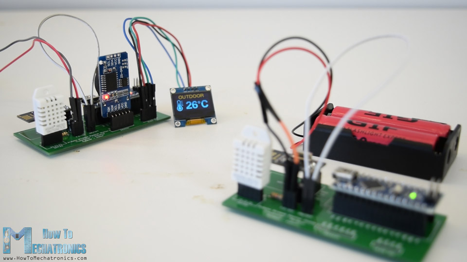
The outdoor temperature and humidity are measured using the DHT22 sensor and this data is wirelessly sent to the indoor unit using the NRF24L01 transceiver modules. At the indoor unit, there is also another DHT22 sensor for measuring the indoor temperature and humidity, as well as a DS3231 Real Time Clock module which can keep track of the time even if the Arduino loses power. All of these data is printed on a 0.96” OLED display.
Arduino Wireless Weather Station Circuit Diagram
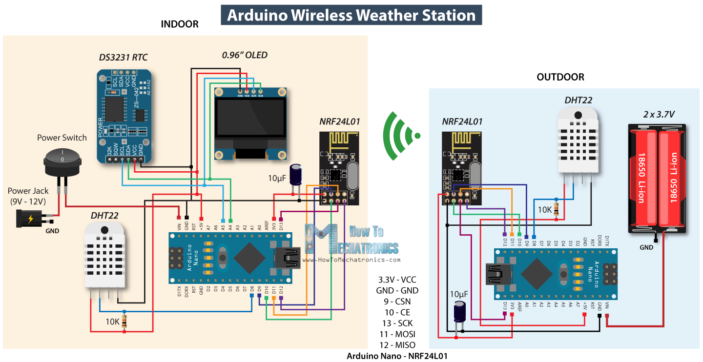
Let’s take a look at the circuit diagram and how this project works. Note that I already have detailed tutorials on how each of these modules work, so for more details you can check them: NRF24L01 Tutorial, DHT22 Tutorial, DS3231 Tutorial .
You can get the components needed for this project from the links below:
- NRF24L01 Transceiver Module………. Amazon / Banggood / AliExpress
- DHT22 Sensor…………….…………………… Amazon / Banggood / AliExpress
- DS3231 Real Time Clock………………….. Amazon / Banggood / AliExpress
- Arduino Nano ………………………….…….. Amazon / Banggood / AliExpress
Disclosure: These are affiliate links. As an Amazon Associate I earn from qualifying purchases.
Both the real time clock module and the OLED display use the I2C protocol for communication with the Arduino so they are connected to the I2C pins or the analog pins number 4 and 5 on the Arduino Nano board. Right next to the NRF24L01 transceiver module there is a capacitor to keep the power supply to it more stable. There is also a pull-up resistor connected to the DHT22 data pin in order the sensor to work properly.
As for the power supply I used 12V DC power adapter for the indoor unit, and on the other side, for powering the outdoor unit I used two Li-on batteries producing around 7.5V. With this configuration the outdoor unit could run for around 10 days before the batteries discharge, because we transmit data periodically and in the meantime we put the Arduino to sleep mode, where the power consumption is only around 7mA.
Custom design PCB
In order to keep the electronics components organized, according to the circuit diagram I designed a custom PCB using the EasyEDA free online circuit design software. We can note that the same PCB can be used for both the indoor and the outdoor unit, only the Arduino board should be programmed differently.
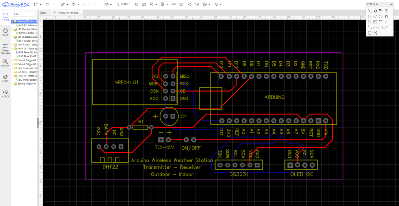
Once we finish the design here, we can simply export the Gerber file which is used for manufacturing the PCB. You can check the EasyEDA project files of Arduino wireless weather station here.
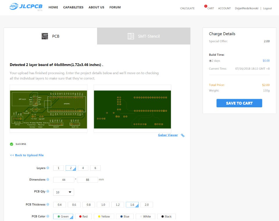
Then we can order our PCB from JLCPCB, which is actually the sponsor of this video.
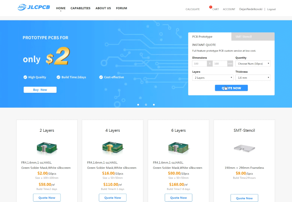
Here we can simply drag and drop the Gerber file and once uploaded we can review our PCB in the Gerber viewer. If everything is all right then we can go on, select the properties that we want for our PCB, and then we can order our PCB at a reasonable price. Note that if it’s your first order from JLCPCB, you can get up to 10 PCBs for only $2.
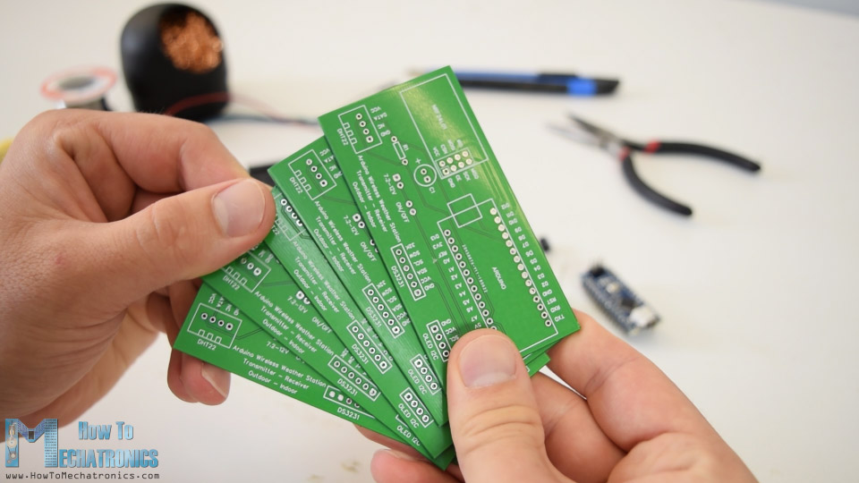
Nevertheless, after several days the PCBs have arrived. The quality of the PCBs is great and everything is exactly the same as in the design.
I started assembling the electronics components of this project by soldering pin headers on to the PCB. In this way we can easily connect and disconnect the components when needed.
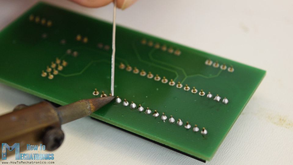
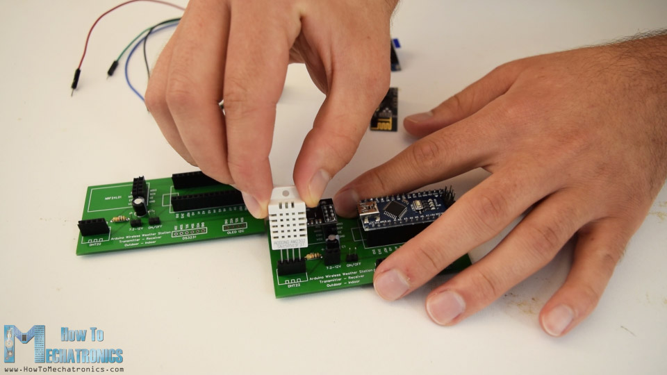
Then I also inserted and soldered the capacitor and the pull-up resistor. With this step done, now we can simply attach the components onto the pin headers of the PCB.
Next, I moved on with making the cases for the project. For that purpose I used 8mm tick MDF board and using a circular saw, I cut all pieces to size.
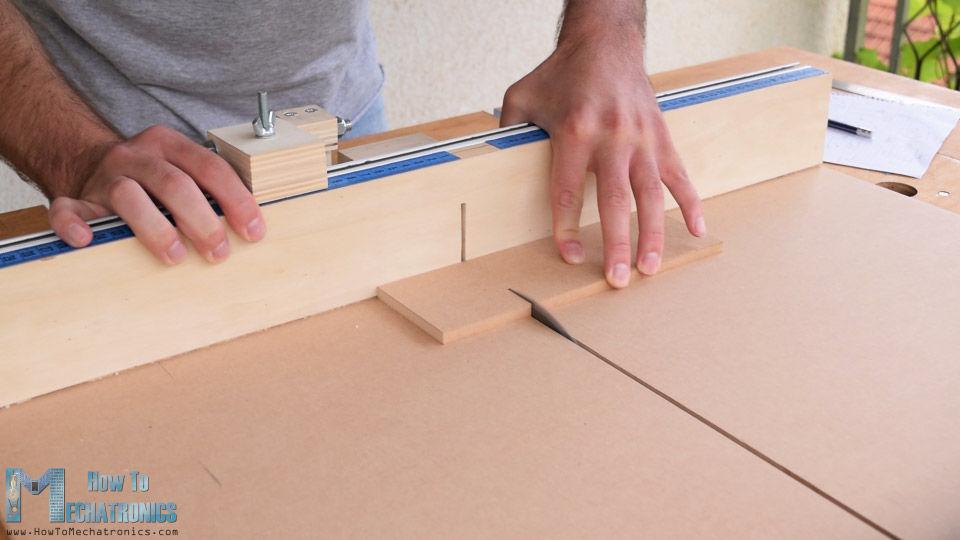
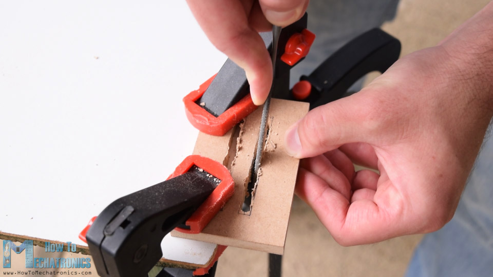
In order to have accurate temperature and humidity measurements the sides of the cases have to allow air to enter the case. So, using a drill and a rasp I made several slots on the side panels on both the indoor and outdoor units.
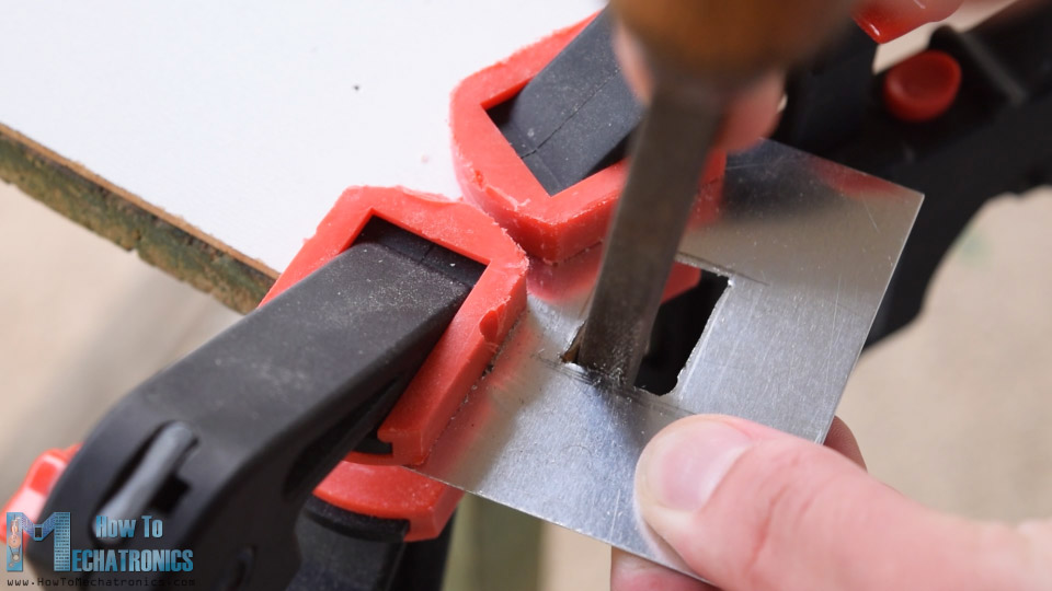
I also made a slot for the OLED display on the front panel, as well as, cut a small piece of aluminum to size which I will later attach on the front panel as a decoration.
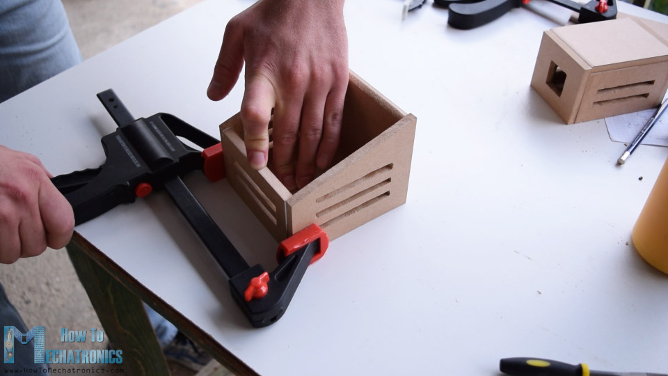
For assembling the cases I used a wood glue and some clamps, as well as some screws.
I painted the cases using a spray paint. I used white paint for the outdoor unit and black one for the indoor unit. After the paint dried out, I simply inserted the PCBs into the cases.
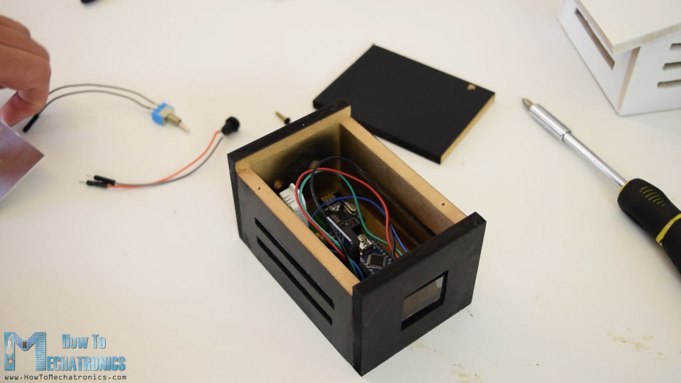
At the back side of the indoor unit I inserted a power jack and a power switch, and at the outdoor unit I used a simple jumper wire as a power switch.
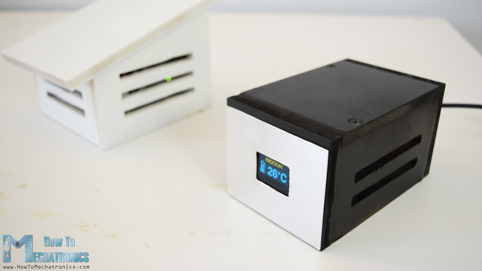
And that’s it, our Arduino wireless weather station is now working, but what’s left in this video is to take a look how the program works.
Arduino Wireless Weather Station Code
Arduino weather station outdoor unit code:
/*
  Arduino Wireless Communication Tutorial
      Outdoor unit - Transmitter

  by Dejan Nedelkovski, www.HowToMechatronics.com

Libraries:
NRF24L01 - TMRh20/RF24, https://github.com/tmrh20/RF24/
DHT22 - DHTlib, https://github.com/RobTillaart/Arduino/tree/master/libraries/DHTlib
LowPower - https://github.com/rocketscream/Low-Power
*/
#include <SPI.h>
#include <nRF24L01.h>
#include <RF24.h>
#include <dht.h>
#include <LowPower.h>

#define dataPin 8 // DHT22 data pin
dht DHT; // Creates a DHT object

RF24 radio(10, 9); // CE, CSN
const byte address[6] = "00001";

char thChar[32] = "";
String thString = "";

void setup() {
  radio.begin();
  radio.openWritingPipe(address);
  radio.setPALevel(RF24_PA_MIN);
  radio.stopListening();

}
void loop() {
  int readData = DHT.read22(dataPin); // Reads the data from the sensor
  int t = DHT.temperature; // Gets the values of the temperature
  int h = DHT.humidity; // Gets the values of the humidity
  thString = String(t) + String(h);
  thString.toCharArray(thChar, 12);
  // Sent the data wirelessly to the indoor unit
  for (int i = 0; i <= 3; i++) {           // Send the data 3 times
    radio.write(&thChar, sizeof(thChar));
    delay(50);
  }
  // Sleep for 2 minutes, 15*8 = 120s
  for (int sleepCounter = 15; sleepCounter > 0; sleepCounter--)
  {
    LowPower.powerDown(SLEEP_8S, ADC_OFF, BOD_OFF);
  }
}Code language: PHP (php)
Description: The outdoor unit is the transmitter of the wireless communication, so here first we need to include the RF24 library, the DHT library, as well as the LowPower library which is used for putting the Arduino to sleep mode.
After defining their instances, the pins to which the modules are connected and some variables, in the setup section we need to initialize the wireless communication address. Then in the loop section, first we read the data from the DHT22 sensor or that’s the temperature and humidity. Initially these values are integers and separated, so I convert them into a single String variable, put them in the character array, and using the radio.write() function, sent this data to the indoor unit. Using the for loop we send the data 3 times in order to be sure that the receiver will get data in case the controller is busy at the time of sending.
At the end we put the Arduino to sleep mode for a particular period of time in order to minimize the power consumption.
Arduino weather station indoor unit code:
/*
  Arduino Wireless Communication Tutorial
        Indoor unit  - Receiver

  by Dejan Nedelkovski, www.HowToMechatronics.com
 Libraries:
 DS3231 - http://www.rinkydinkelectronics.com/library.php?id=73
 U8G2 - https://github.com/olikraus/u8g2
*/
#include <SPI.h>
#include <nRF24L01.h>
#include <RF24.h>
#include <dht.h>
#include <DS3231.h>
#include <U8g2lib.h>
#include <Wire.h>

#define dataPin 8 // DHT22 sensor
dht DHT; // Creats a DHT object
DS3231  rtc(SDA, SCL);
U8G2_SSD1306_128X64_NONAME_1_HW_I2C u8g2(U8G2_R0, /* reset=*/ U8X8_PIN_NONE);

RF24 radio(10, 9); // CE, CSN
const byte address[6] = "00001";

char text[6] = "";
int readDHT22, t, h;
String inTemp, inHum, outTemp, outHum;
String rtcTime, rtcDate;
int draw_state = 0;
unsigned long previousMillis = 0;
long interval = 3000;

#define Temperature_20Icon_width 27
#define Temperature_20Icon_height 47
static const unsigned char Temperature_20Icon_bits[] U8X8_PROGMEM = {
  0x00, 0x00, 0x00, 0x00, 0x00, 0x3f, 0x00, 0x00, 0x80, 0x7f, 0x00, 0x00,
  0xc0, 0xe1, 0x00, 0x00, 0xe0, 0xc0, 0x01, 0x00, 0x60, 0x80, 0xf9, 0x03,
  0x60, 0x80, 0x01, 0x00, 0x60, 0x80, 0x01, 0x00, 0x60, 0x80, 0x79, 0x00,
  0x60, 0x80, 0x01, 0x00, 0x60, 0x80, 0x01, 0x00, 0x60, 0x80, 0xf9, 0x03,
  0x60, 0x80, 0x01, 0x00, 0x60, 0x80, 0x01, 0x00, 0x60, 0x8c, 0x79, 0x00,
  0x60, 0x9e, 0x01, 0x00, 0x60, 0x9e, 0x01, 0x00, 0x60, 0x9e, 0xf9, 0x03,
  0x60, 0x9e, 0x01, 0x00, 0x60, 0x9e, 0x01, 0x00, 0x60, 0x9e, 0x79, 0x00,
  0x60, 0x9e, 0x01, 0x00, 0x60, 0x9e, 0x01, 0x00, 0x60, 0x9e, 0xf9, 0x03,
  0x60, 0x9e, 0x01, 0x00, 0x60, 0x9e, 0x01, 0x00, 0x60, 0x9e, 0x01, 0x00,
  0x70, 0x9e, 0x03, 0x00, 0x38, 0x1e, 0x07, 0x00, 0x18, 0x3e, 0x0e, 0x00,
  0x1c, 0x3f, 0x0c, 0x00, 0x0c, 0x7f, 0x18, 0x00, 0x8c, 0xff, 0x18, 0x00,
  0x8e, 0xff, 0x38, 0x00, 0xc6, 0xff, 0x31, 0x00, 0xc6, 0xff, 0x31, 0x00,
  0xc6, 0xff, 0x31, 0x00, 0x8e, 0xff, 0x38, 0x00, 0x8c, 0xff, 0x18, 0x00,
  0x0c, 0x7f, 0x1c, 0x00, 0x3c, 0x1c, 0x0e, 0x00, 0x78, 0x00, 0x06, 0x00,
  0xe0, 0x80, 0x07, 0x00, 0xe0, 0xff, 0x03, 0x00, 0x80, 0xff, 0x00, 0x00,
  0x00, 0x1c, 0x00, 0x00, 0x00, 0x00, 0x00, 0x00
};


#define Humidity_20Icon_width 27
#define Humidity_20Icon_height 47
static const unsigned char Humidity_20Icon_bits[] U8X8_PROGMEM = {
  0x00, 0x00, 0x00, 0x00, 0x00, 0x70, 0x00, 0x00, 0x00, 0x70, 0x00, 0x00,
  0x00, 0x70, 0x00, 0x00, 0x00, 0xf8, 0x00, 0x00, 0x00, 0xdc, 0x00, 0x00,
  0x00, 0xdc, 0x01, 0x00, 0x00, 0x8e, 0x01, 0x00, 0x00, 0x86, 0x03, 0x00,
  0x00, 0x06, 0x03, 0x00, 0x00, 0x03, 0x07, 0x00, 0x80, 0x03, 0x06, 0x00,
  0x80, 0x01, 0x0c, 0x00, 0xc0, 0x01, 0x1c, 0x00, 0xc0, 0x00, 0x18, 0x00,
  0xe0, 0x00, 0x38, 0x00, 0x60, 0x00, 0x30, 0x00, 0x70, 0x00, 0x70, 0x00,
  0x30, 0x00, 0xe0, 0x00, 0x38, 0x00, 0xc0, 0x00, 0x18, 0x00, 0xc0, 0x01,
  0x1c, 0x00, 0x80, 0x01, 0x0c, 0x00, 0x80, 0x03, 0x0e, 0x00, 0x80, 0x03,
  0x06, 0x00, 0x00, 0x03, 0x06, 0x00, 0x00, 0x03, 0x07, 0x00, 0x00, 0x07,
  0x03, 0x00, 0x00, 0x06, 0x03, 0x00, 0x00, 0x06, 0x03, 0x00, 0x00, 0x06,
  0x63, 0x00, 0x00, 0x06, 0x63, 0x00, 0x00, 0x06, 0x63, 0x00, 0x00, 0x06,
  0xe3, 0x00, 0x00, 0x06, 0xc7, 0x00, 0x00, 0x06, 0xc6, 0x01, 0x00, 0x07,
  0x86, 0x03, 0x00, 0x03, 0x0e, 0x1f, 0x00, 0x03, 0x0e, 0x1e, 0x80, 0x01,
  0x1c, 0x00, 0xc0, 0x01, 0x38, 0x00, 0xe0, 0x00, 0x78, 0x00, 0x70, 0x00,
  0xf0, 0x00, 0x38, 0x00, 0xe0, 0x07, 0x1f, 0x00, 0x80, 0xff, 0x0f, 0x00,
  0x00, 0xff, 0x03, 0x00, 0x00, 0x00, 0x00, 0x00
};

void setup() {
  radio.begin();
  radio.openReadingPipe(0, address);
  radio.setPALevel(RF24_PA_MIN);
  radio.startListening();
  u8g2.begin();
  rtc.begin();
}
void loop() {
  if (radio.available()) {
    radio.read(&text, sizeof(text)); // Read incoming data
    outTemp = String(text[0]) + String(text[1]) + char(176) + "C"; // Outdoor Temperature
    outHum = String(text[2]) + String(text[3]) + "%"; // Outdoor Humidity
  }

  unsigned long currentMillis = millis();
  if (currentMillis - previousMillis > interval) {
    previousMillis = currentMillis;
    u8g2.firstPage();
    do {
      switch (draw_state ) {
        case 0: drawDate(); break;
        case 1: drawInTemperature(); break;
        case 2: drawInHumidity(); break;
        case 3: drawOutTemperature(); break;
        case 4: drawOutHumidity(); break;
      }
    } while ( u8g2.nextPage() );
    draw_state++;
    if (draw_state > 4) {
      draw_state = 0;
    }
  }
}

void drawDate() {
  String dowa = rtc.getDOWStr();
  dowa.remove(3);
  rtcDate = dowa + " " + rtc.getDateStr();
  u8g2.setFont(u8g2_font_timB14_tr);
  u8g2.setCursor(0, 15);
  rtcTime = rtc.getTimeStr(); // DS3231 RTC time
  rtcTime.remove(5);
  u8g2.print(rtcDate);
  u8g2.setFont(u8g2_font_fub30_tf);
  u8g2.setCursor(8, 58);
  u8g2.print(rtcTime);
}

void drawInTemperature() {
  readDHT22 = DHT.read22(dataPin); // Reads the data from the sensor
  t = DHT.temperature; // Gets the values of the temperature
  inTemp = String(t) + char(176) + "C";
  u8g2.setFont(u8g2_font_helvR14_tr);
  u8g2.setCursor(24, 15);
  u8g2.print("INDOOR");
  u8g2.setFont(u8g2_font_fub30_tf);
  u8g2.setCursor(36, 58);
  u8g2.print(inTemp);
  u8g2.drawXBMP( 0, 17, Temperature_20Icon_width, Temperature_20Icon_height, Temperature_20Icon_bits);
}

void drawInHumidity() {
  h = DHT.humidity; // Gets the values of the humidity
  inHum = String(h) + "%";
  u8g2.setFont(u8g2_font_helvR14_tr);
  u8g2.setCursor(24, 15);
  u8g2.print("INDOOR");
  u8g2.setFont(u8g2_font_fub30_tf);
  u8g2.setCursor(36, 58);
  u8g2.print(inHum);
  u8g2.drawXBMP( 0, 17, Humidity_20Icon_width, Humidity_20Icon_height, Humidity_20Icon_bits);
}

void drawOutTemperature() {
  u8g2.setFont(u8g2_font_helvR14_tr);
  u8g2.setCursor(12, 15);
  u8g2.print("OUTDOOR");
  u8g2.setFont(u8g2_font_fub30_tf);
  u8g2.setCursor(36, 58);
  u8g2.print(outTemp);
  u8g2.drawXBMP( 0, 17, Temperature_20Icon_width, Temperature_20Icon_height, Temperature_20Icon_bits);
}
void drawOutHumidity() {
  u8g2.setFont(u8g2_font_helvR14_tr);
  u8g2.setCursor(12, 15);
  u8g2.print("OUTDOOR");
  u8g2.setFont(u8g2_font_fub30_tf);
  u8g2.setCursor(36, 58);
  u8g2.print(outHum);
  u8g2.drawXBMP( 0, 17, Humidity_20Icon_width, Humidity_20Icon_height, Humidity_20Icon_bits);
}Code language: PHP (php)
Description: On the other side, at the indoor unit or the receiver, we need to include two more libraries, one for the DS3231 real time clock module and one for the OLED display, the U8G2 library. In the same way as previously, we need to define the instances, the pins and some variables need for the program below. Also here we need to define the temperature and humidity icons as bitmaps.
Temperature icon bitmap:
#define Temperature_20Icon_width 27
#define Temperature_20Icon_height 47
static const unsigned char Temperature_20Icon_bits[] U8X8_PROGMEM = {
0x00, 0x00, 0x00, 0x00, 0x00, 0x3f, 0x00, 0x00, 0x80, 0x7f, 0x00, 0x00,
0xc0, 0xe1, 0x00, 0x00, 0xe0, 0xc0, 0x01, 0x00, 0x60, 0x80, 0xf9, 0x03,
0x60, 0x80, 0x01, 0x00, 0x60, 0x80, 0x01, 0x00, 0x60, 0x80, 0x79, 0x00,
0x60, 0x80, 0x01, 0x00, 0x60, 0x80, 0x01, 0x00, 0x60, 0x80, 0xf9, 0x03,
0x60, 0x80, 0x01, 0x00, 0x60, 0x80, 0x01, 0x00, 0x60, 0x8c, 0x79, 0x00,
0x60, 0x9e, 0x01, 0x00, 0x60, 0x9e, 0x01, 0x00, 0x60, 0x9e, 0xf9, 0x03,
0x60, 0x9e, 0x01, 0x00, 0x60, 0x9e, 0x01, 0x00, 0x60, 0x9e, 0x79, 0x00,
0x60, 0x9e, 0x01, 0x00, 0x60, 0x9e, 0x01, 0x00, 0x60, 0x9e, 0xf9, 0x03,
0x60, 0x9e, 0x01, 0x00, 0x60, 0x9e, 0x01, 0x00, 0x60, 0x9e, 0x01, 0x00,
0x70, 0x9e, 0x03, 0x00, 0x38, 0x1e, 0x07, 0x00, 0x18, 0x3e, 0x0e, 0x00,
0x1c, 0x3f, 0x0c, 0x00, 0x0c, 0x7f, 0x18, 0x00, 0x8c, 0xff, 0x18, 0x00,
0x8e, 0xff, 0x38, 0x00, 0xc6, 0xff, 0x31, 0x00, 0xc6, 0xff, 0x31, 0x00,
0xc6, 0xff, 0x31, 0x00, 0x8e, 0xff, 0x38, 0x00, 0x8c, 0xff, 0x18, 0x00,
0x0c, 0x7f, 0x1c, 0x00, 0x3c, 0x1c, 0x0e, 0x00, 0x78, 0x00, 0x06, 0x00,
0xe0, 0x80, 0x07, 0x00, 0xe0, 0xff, 0x03, 0x00, 0x80, 0xff, 0x00, 0x00,
0x00, 0x1c, 0x00, 0x00, 0x00, 0x00, 0x00, 0x00
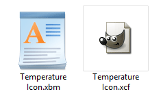
};Code language: PHP (php)For this purpose we can use GIMP, an open source image editor, through which we can draw anything and then export it as bitmap(.xbm).
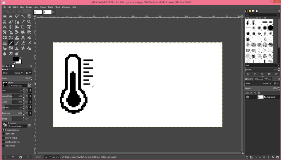
Then we can open this file using a notepad and from there we can copy the bitmap into the Arduino code.
Note that here we can define the bitmap as constant using the PROGMEM variable modifier, and it that way the bitmap will be stored in the flash memory instead of the SRAM of the Arduino board.
static const unsigned char Temperature_20Icon_bits[] U8X8_PROGMEM // Save in the Flash memory
static unsigned char Temperature_20Icon_bits[] // Save in the SRAM
In the setup section we need to initialize the wireless communication as well as initialize the OLED display and the real time clock module.
Then in the loop section we constantly check whether there is an incoming data available to be read via the NRF24L01 modules. If true, using the radio.read() function we read it, and store the first two characters into the temperature String variable, and the next two characters into the humidity String variable.
Then we use the millis() function in order to display the various data on the display at intervals defined with the interval variable which I set it to 3 seconds. We are using the millis() function because in this way the rest of the code can be repeatedly executed, while in case we use the delay() function, the program waits for that period so in that way we would probably miss the incoming data from the outdoor unit.
Next, using the firstPage() and nextPage() function of the U8G2 library we print the five different screens which are defined with the custom functions.
The drawDate() custom function gets the date and time information from the real time clock module and prints it on the display appropriately. The drawInTemperature() function reads the indoor temperature and prints it appropriately on the display. In fact, the same method is used for printing all of the screens on the display.
So that would be all, I hope you enjoyed this Arduino project and learned something new. Feel free to ask any question in the comments section below.
Must say that this project taught me a whole host of things being new and very green about these things ,I am a retired joiner carpenter so the building of the boxes etc was easy for me . Next step I learned about PCBs of this site it was easy to order my very first PCBs Learned about Gerber files
Then the biggest problem programming, for you newies out there if you buy as I did cheap clone arduino nano look on line or youtube about setting these up, this was a week of pulling hair shouting at the screen and lots of swearing found one video on youtube 5 Most common Arduino Nano Clone Problems and their Solutions This is a great vid for wooden heads like me . So if like me you are brand new at this sort of thing keep pegging away at it you will get there in the end MANY THANKS
Hello I am currently working on this project because this would be a perfect addition to my small workbench but I keep getting the same error code.
“Arduino: 1.8.7 (Windows 10), Board: “Arduino Nano, ATmega328P”
Arduino_Wireless_Weather_Station_Indoor_Reciever:15:21: error: U8g2lib.h: No such file or directory
compilation terminated.
exit status 1
U8g2lib.h: No such file or directory
Invalid library found in C:\Users\Jim\Documents\Arduino\libraries\u8g2: no headers files (.h) found in C:\Users\Jim\Documents\Arduino\libraries\u8g2
This report would have more information with
“Show verbose output during compilation”
option enabled in File -> Preferences.
I have downloaded and loaded the exact U8G2 library you specify in this How-To but as you can see the program refuses to recognize it even though it has been installed correctly in the Libraries folder. Would you have any advise. I really want this to work. Thank you
Hello,
thanks for the code. Everything is working fine except that the outdoor temperature and humidity don’t change. The DHT22 Sensor is working fine. Could it be that there is a problem with the sending/receiving the data right ? Do you know what it could be in the code maybe.
Well yeah, I guess the radio communication is the problem. Try to more simple code to test whether the communication works properly, for example, try to codes form my basic NRF24L01 module tutorial.
Hello,
the thing is that it shows the outside temperature and humidity but it just shows it once and if the temperature or humidity changes in the outside unit it doesn’t show the changing on the display.
Do you know how i can solve this problem ?
good day sir
i am using dht11, does it work with these setting? thus it hav the same library?
thankss much
Yes, DHT11 should work the same as DHT22.
How could I adjust the code to use a 16×2 LCD screen? Any help would be appreciated
Hello, great tutorial! quick question how would i use a 16×2 lcd without i2c instead of Oled? thanks
Thanks and sure you can use that LCD, but you would need to adjust the code appropriately.
Could you please give me an example? Ive used 16×2 LCD before but not with NRF24l01 and im pretty confused. It says on the arduino projects list that you can use this screen so I assumed the appropriate adjustments would be provided?
Hello, how to set date and time to RTC ?
Uncomment the set functions in the setup section of code.
I thought this would be a great idea as I always wanted my own weather station and decided to give it a try.
I followed your instructions regarding the electronic side of things and tested each part as I went.
However, when trying to upload the script into the Nano or my Uno it refuses to recognise the “dht.h.” file even though I located it and placed it in the same folder as the script. Has anyone else had this problem or is there a route to solve it
Hey, it’s a problem with the library for sure. Make sure you download and install it correctly into your Arduino libraries directory. I could notice that the link I included for the library on GitHub doesn’t have a download button now. You need to go two steps back, “Arduino/libraries/DHTlib/”. So here at the Arduino page the download button will appear, so download all Libraries and copy the DHT library folder into your Arduino libraries directory. I hope this will work thinks out.