In this tutorial we will learn how to build an Arduino wireless network, composed of multiple NR24L01 transceiver modules. You can watch the following video or read the written tutorial below.
Overview
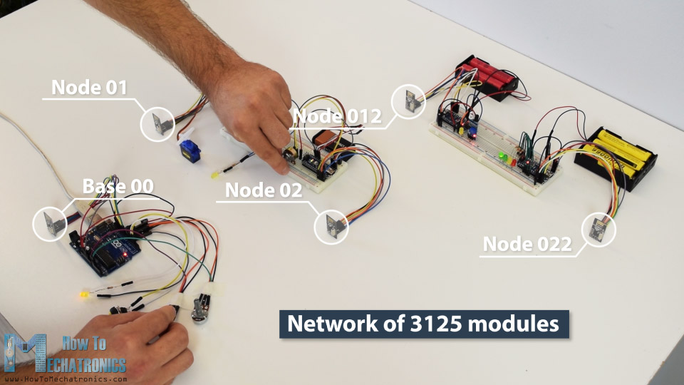
As an example I made a network of 5 nodes and each of them can communicate with any node in the network and at the same time they can work as both transmitters and receivers. This example is actually set up in a way that explains how to make a much larger network, or to be precise, we can have a total of 3125 modules communicating to each other on a single RF channel. So let’s take a look how it works.
In my previous tutorials we have already learned how to make a wireless communication between two Arduino boards using the NRF24L01 modules and the RF24 library. Now in addition to this library, we will use the RF24Network library, which enables in an easy way to build an Arduino wireless network with many boards communicating to each other. Here’s how the network topology works.
Multiple NRF24L01 modules communication
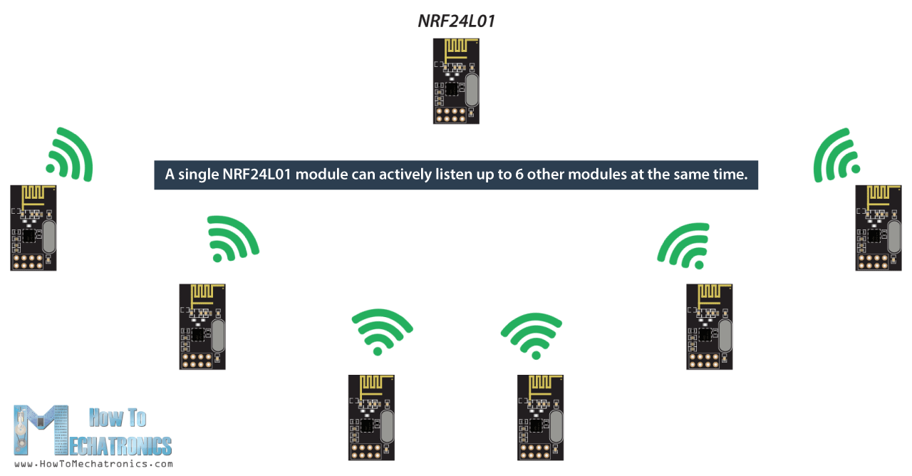
A single NRF24L01 module can actively listen up to 6 other modules at the same time.
This ability is utilized by the RF24Network library to generate a network arranged in a tree topology, where one node is the base, and all other nodes are children of either that node or of another. Each node can have up to 5 children, and this can go 5 levels deep, which means we can create a network of total 3125 nodes. Each node must be defined with a 15-bit address, which precisely describes the position of the node within the tree.
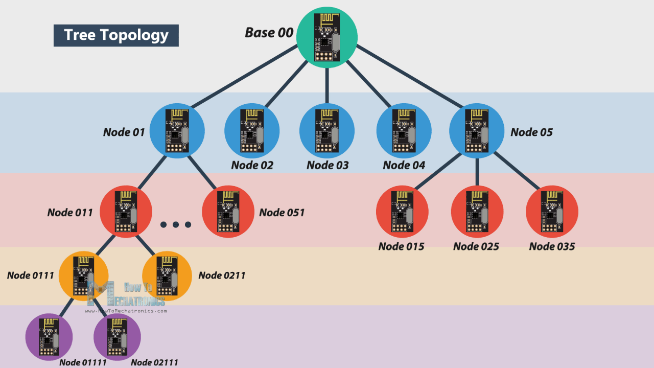
We can actually define the addresses of the nodes in octal format. So, the address of the master or the base is 00, the base children addresses are 01 to 05, the 01 node children addresses are 011 to 051 and so on.
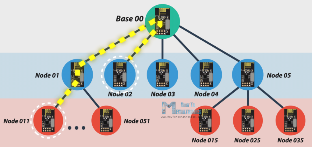
Note that if node 011 wants to talk to the node 02, the communication will have to go through the node 01 and the base node 00, so these two nodes must be active all the time in order the communication to be successful.
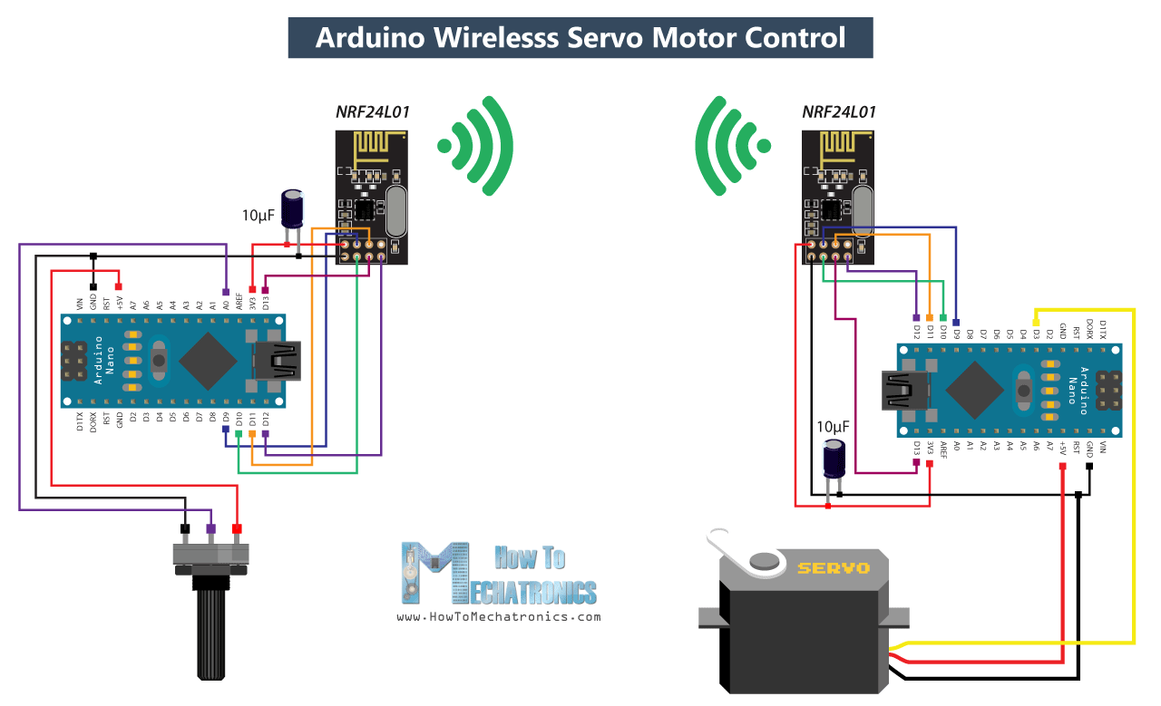
Arduino Wireless Servo Motor Control using the RF24Network Library
Before we explain the main example of this tutorial, for better understanding how the library works let’s make a simpler example of two Arduino boards communicating to each other. Here’s the circuit diagram for this example.
You can get the components needed for this Arduino Tutorial from the links below:
- NRF24L01 Transceiver Module……….. Amazon / Banggood / AliExpress
- Servo Motor …………………………………… Amazon / Banggood / AliExpress
- Potentiometer ……………………………….. Amazon / Banggood / AliExpress
- Arduino Nano ……………………………….. Amazon / Banggood / AliExpress
Disclosure: These are affiliate links. As an Amazon Associate I earn from qualifying purchases.
So using the potentiometer at the first Arduino we will control the servo motor at the second Arduino. Let’s take a look at the source codes now.
Here’s the code at the potentiometer side:
/*
  Arduino Wireless Network - Multiple NRF24L01 Tutorial
 == Example 01 - Servo Control / Node 00 - Potentiometer ==
  by Dejan, www.HowToMechatronics.com
  Libraries:
  nRF24/RF24, https://github.com/nRF24/RF24
  nRF24/RF24Network, https://github.com/nRF24/RF24Network
*/
#include <RF24.h>
#include <RF24Network.h>
#include <SPI.h>

RF24 radio(10, 9);               // nRF24L01 (CE,CSN)
RF24Network network(radio);      // Include the radio in the network
const uint16_t this_node = 00;   // Address of this node in Octal format ( 04,031, etc)
const uint16_t node01 = 01;

void setup() {
  SPI.begin();
  radio.begin();
  network.begin(90, this_node);  //(channel, node address)
}

void loop() {
  network.update();
  unsigned long potValue = analogRead(A0);  // Read the potentiometer value
  unsigned long angleValue = map(potValue, 0, 1023, 0, 180); // Convert the value to 0-180
  RF24NetworkHeader header(node01);     // (Address where the data is going)
  bool ok = network.write(header, &angleValue, sizeof(angleValue)); // Send the data
}Code language: PHP (php)
First we need to include both libraries RF24 and RF24Network, as well as the SPI library. Then we need to create the RF24 object, and include it into the RF24Network object. Here we need define the addresses of the nodes in octal format, or 00 for this node, and 01 for the other node at the servo side.
In the setup section we need to initialize the network, by setting the channel and the address of this node.
In the loop section we constantly need to call the update() function through which all action in the network happens. Then we read the value of the potentiometer and convert it into a value from 0 to 180 which is suitable for the servo control. Then we create a network header where we assign the address of the node where the data is going. At the end, using the write() function we send the data to the other node. So here the first parameter contains the addresses information, the second parameter points which data will be send, and the third parameter is the size of the data.
Here’s the code at the servo side:
/*
  Arduino Wireless Network - Multiple NRF24L01 Tutorial
  == Example 01 - Servo Control / Node 01 - Servo motor ==
*/
#include <RF24.h>
#include <RF24Network.h>
#include <SPI.h>
#include <Servo.h>

RF24 radio(10, 9);               // nRF24L01 (CE,CSN)
RF24Network network(radio);      // Include the radio in the network
const uint16_t this_node = 01;   // Address of our node in Octal format ( 04,031, etc)

Servo myservo;  // create servo object to control a servo

void setup() {
  SPI.begin();
  radio.begin();
  network.begin(90, this_node); //(channel, node address)
  myservo.attach(3);   // (servo pin)
}

void loop() {
  network.update();
  while ( network.available() ) {     // Is there any incoming data?
    RF24NetworkHeader header;
    unsigned long incomingData;
    network.read(header, &incomingData, sizeof(incomingData)); // Read the incoming data
    myservo.write(incomingData);  // tell servo to go to a particular angle
  }
}Code language: PHP (php)
On the other side, at the servo motor, we need to define the libraries and the objects in the same way as explained earlier. Here the address of this node in octal format is 01. After defining the servo motor, in the loop section, using the while() loop and the available() function we constantly check whether there is any incoming data. If true, we create a network header through which the data will be accepted and also a variable where the data will be stored. Then using the read() function we read the data, and store it into the incomingData variable. At the end we use this data to move the servo motor according to the potentiometer from the other node.
Arduino Wireless Network with Multiple NRF24L01 Modules
After understanding this example we can move on with the main example of this tutorial and build a wireless network of 5 Arduinos communicating to each other. Here’s a block diagram of the example.
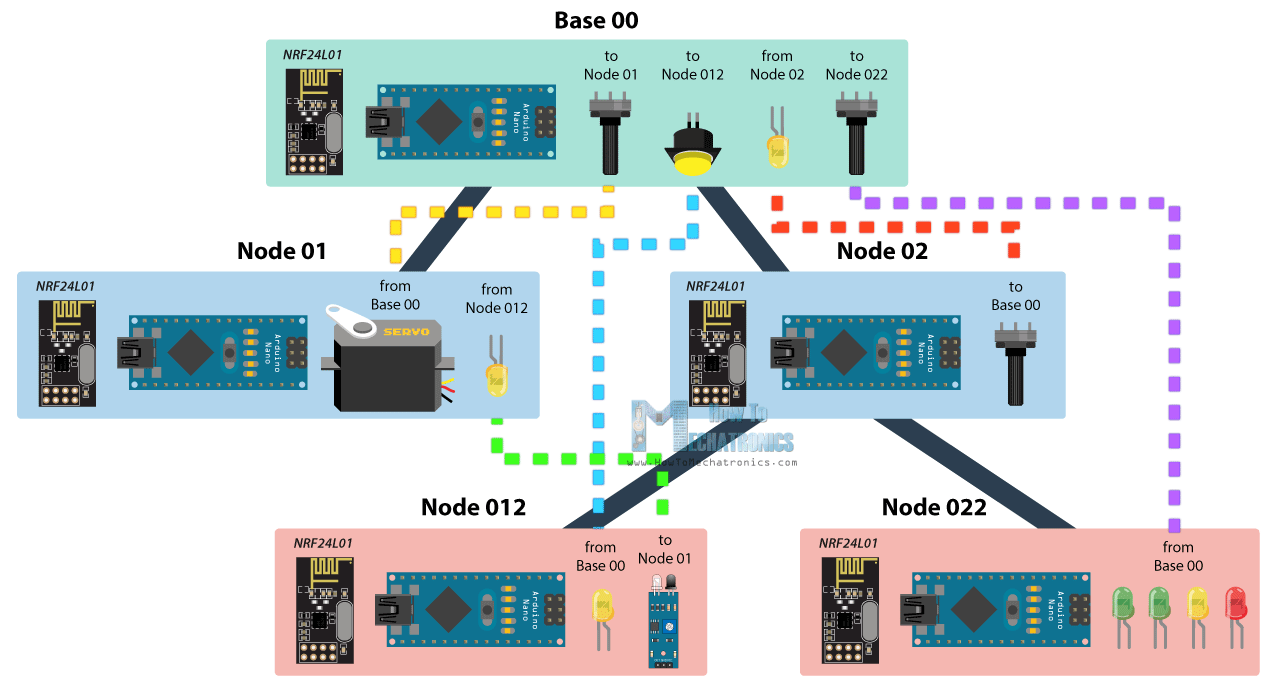
So from the base, using a potentiometer we will control the servo motor at the node 01, with the second potentiometer we will control the LEDs at the node 022, using the button we will control the LED at node 012, and the LED here at the base will be control using the potentiometer at node 02. Also using the infrared sensor at the node 012 we will control the LED at node 01. So we can notice that this example explains how to both transmit and receive data at the same time, as well as how to communicate with nodes from different branches. Let’s take a look at the Arduino codes now.
Related: DIY Arduino RC Transmitter
Base 00 source code
/*
  Arduino Wireless Network - Multiple NRF24L01 Tutorial
          == Base/ Master Node 00==
  by Dejan, www.HowToMechatronics.com
  Libraries:
  nRF24/RF24, https://github.com/nRF24/RF24
  nRF24/RF24Network, https://github.com/nRF24/RF24Network
*/

#include <RF24Network.h>
#include <RF24.h>
#include <SPI.h>

#define button 2
#define led 3

RF24 radio(10, 9);               // nRF24L01 (CE,CSN)
RF24Network network(radio);      // Include the radio in the network
const uint16_t this_node = 00;   // Address of this node in Octal format ( 04,031, etc)
const uint16_t node01 = 01;      // Address of the other node in Octal format
const uint16_t node012 = 012;
const uint16_t node022 = 022;

void setup() {
  SPI.begin();
  radio.begin();
  network.begin(90, this_node);  //(channel, node address)
  radio.setDataRate(RF24_2MBPS);
  pinMode(button, INPUT_PULLUP);
  pinMode(led, OUTPUT);
}

void loop() {
  network.update();
  //===== Receiving =====//
  while ( network.available() ) {     // Is there any incoming data?
    RF24NetworkHeader header;
    unsigned long incomingData;
    network.read(header, &incomingData, sizeof(incomingData)); // Read the incoming data
    analogWrite(led, incomingData);    // PWM output to LED 01 (dimming)
  }
  //===== Sending =====//
  // Servo control at Node 01
  unsigned long potValue = analogRead(A0);
  unsigned long angleValue = map(potValue, 0, 1023, 0, 180); // Suitable for servo control
  RF24NetworkHeader header2(node01);     // (Address where the data is going)
  bool ok = network.write(header2, &angleValue, sizeof(angleValue)); // Send the data

  // LED Control at Node 012
  unsigned long buttonState = digitalRead(button);
  RF24NetworkHeader header4(node012);    // (Address where the data is going)
  bool ok3 = network.write(header4, &buttonState, sizeof(buttonState)); // Send the data

  // LEDs control at Node 022
  unsigned long pot2Value = analogRead(A1);
  RF24NetworkHeader header3(node022);    // (Address where the data is going)
  bool ok2 = network.write(header3, &pot2Value, sizeof(pot2Value)); // Send the data
}Code language: PHP (php)
So at the base or the master node we need to define the libraries and the objects as explained earlier, and also define all other nodes to which the master will send data. In the loop section we start by constantly checking whether there is any incoming data. If so, we read the data, store it into the incomingData variable and use it to control the LED brightness. This data is actually coming from the potentiometer from node 02. If we take a look at its code, we can notice that setup is pretty much the same. The important thing is to assign the right address to where we want to send data. In this case, that’s the master 00. So after reading the potentiometer value and converting it into suitable PWM value from 0 to 255, we send this data to the master. We can notice here that I used the millis() function send the data at intervals of 10 milliseconds.
Node 02 source code
/*
  Arduino Wireless Network - Multiple NRF24L01 Tutorial
        == Node 02 (Child of Master node 00) ==
*/

#include <RF24Network.h>
#include <RF24.h>
#include <SPI.h>

RF24 radio(10, 9);               // nRF24L01 (CE,CSN)
RF24Network network(radio);      // Include the radio in the network
const uint16_t this_node = 02;   // Address of our node in Octal format ( 04,031, etc)
const uint16_t master00 = 00;    // Address of the other node in Octal format

const unsigned long interval = 10;  //ms  // How often to send data to the other unit
unsigned long last_sent;            // When did we last send?

void setup() {
  SPI.begin();
  radio.begin();
  network.begin(90, this_node);  //(channel, node address)
  radio.setDataRate(RF24_2MBPS);
}

void loop() {
  network.update();
  //===== Sending =====//
  unsigned long now = millis();
  if (now - last_sent >= interval) {   // If it's time to send a data, send it!
    last_sent = now;
    unsigned long potValue = analogRead(A0);
    unsigned long ledBrightness = map(potValue, 0, 1023, 0, 255);
    RF24NetworkHeader header(master00);   // (Address where the data is going)
    bool ok = network.write(header, &ledBrightness, sizeof(ledBrightness)); // Send the data
  }
}Code language: PHP (php)
Next, from the master, we send the potentiometer data to the node 01 for controlling the servo motor.
Node 01 source code
/*
  Arduino Wireless Network - Multiple NRF24L01 Tutorial
        == Node 02 (Child of Master node 00) ==
*/

#include <RF24Network.h>
#include <RF24.h>
#include <SPI.h>
#include <Servo.h>

#define led 2

RF24 radio(10, 9);               // nRF24L01 (CE,CSN)
RF24Network network(radio);      // Include the radio in the network
const uint16_t this_node = 01;   // Address of our node in Octal format ( 04,031, etc)
const uint16_t master00 = 00;    // Address of the other node in Octal format

Servo myservo;  // create servo object to control a servo

void setup() {
  SPI.begin();
  radio.begin();
  network.begin(90, this_node); //(channel, node address)
  radio.setDataRate(RF24_2MBPS);
  myservo.attach(3);   // (servo pin)
  pinMode(led, OUTPUT);
}

void loop() {
  network.update();
  //===== Receiving =====//
  while ( network.available() ) {     // Is there any incoming data?
    RF24NetworkHeader header;
    unsigned long incomingData;
    network.read(header, &incomingData, sizeof(incomingData)); // Read the incoming data
    if (header.from_node == 0) {    // If data comes from Node 02
      myservo.write(incomingData);  // tell servo to go to a particular angle
    }
    if (header.from_node == 10) {    // If data comes from Node 012
      digitalWrite(led, !incomingData);  // Turn on or off the LED 02
    }
  }
}Code language: PHP (php)
The node 01 is actually receiving data from two different nodes, one for the servo control and the other for the LED control which comes from the infrared sensor from the node 012.
Node 012 source code
/*
  Arduino Wireless Network - Multiple NRF24L01 Tutorial
            == Node 012 (child of Node 02)==
*/

#include <RF24Network.h>
#include <RF24.h>
#include <SPI.h>

#define led 2
#define IR 3

RF24 radio(10, 9);               // nRF24L01 (CE,CSN)
RF24Network network(radio);      // Include the radio in the network
const uint16_t this_node = 012;  // Address of our node in Octal format ( 04,031, etc)
const uint16_t node01 = 01;    // Address of the other node in Octal format

void setup() {
  SPI.begin();
  radio.begin();
  network.begin(90, this_node);  //(channel, node address)
  radio.setDataRate(RF24_2MBPS);
  pinMode(led, OUTPUT);
  pinMode(IR, INPUT);
}

void loop() {
  network.update();
  //===== Receiving =====//
  while ( network.available() ) {     // Is there any incoming data?
    RF24NetworkHeader header;
    unsigned long buttonState;
    network.read(header, &buttonState, sizeof(buttonState)); // Read the incoming data
    digitalWrite(led, !buttonState); // Turn on or off the LED
  }
  //===== Sending =====//
  unsigned long irV = digitalRead(IR); // Read IR sensor
  RF24NetworkHeader header8(node01);
  bool ok = network.write(header8, &irV, sizeof(irV)); // Send the data
}Code language: PHP (php)
In such a case, we use the header.from_node attribute in order get information from which node does the data come from. In case the incoming data is from the master, we use it to control the servo, and in case the incoming data is from the node 012, we use it to control the LED.
At the node 012 we have both transmitting and receiving. The infrared sensor controls the previously mentioned LED at node 01 and the LED here is control from the button at the master.
Node 022 source code
/*
  Arduino Wireless Network - Multiple NRF24L01 Tutorial
            == Node 022 (child of Node 02)==
*/

#include <RF24Network.h>
#include <RF24.h>
#include <SPI.h>

#define led1 2
#define led2 3
#define led3 4
#define led4 5

RF24 radio(10, 9);               // nRF24L01 (CE,CSN)
RF24Network network(radio);      // Include the radio in the network
const uint16_t this_node = 022;  // Address of our node in Octal format ( 04,031, etc)
const uint16_t master00 = 00;    // Address of the other node in Octal format

void setup() {
  SPI.begin();
  radio.begin();
  network.begin(90, this_node);  //(channel, node address)
  radio.setDataRate(RF24_2MBPS);
  pinMode(led1, OUTPUT);
  pinMode(led2, OUTPUT);
  pinMode(led3, OUTPUT);
  pinMode(led4, OUTPUT);
}

void loop() {
  network.update();
  //===== Receiving =====//
  while ( network.available() ) {     // Is there any incoming data?
    RF24NetworkHeader header;
    unsigned long potValue;
    network.read(header, &potValue, sizeof(potValue)); // Read the incoming data
    // Turn on the LEDs as depending on the incoming value from the potentiometer
    if (potValue > 240) {
      digitalWrite(led1, HIGH);
    } else {
      digitalWrite(led1, LOW);
    }
    if (potValue > 480) {
      digitalWrite(led2, HIGH);
    } else {
      digitalWrite(led2, LOW);
    }
    if (potValue > 720) {
      digitalWrite(led3, HIGH);
    } else {
      digitalWrite(led3, LOW);
    }
    if (potValue > 960) {
      digitalWrite(led4, HIGH);
    } else {
      digitalWrite(led4, LOW);
    }
  }
}Code language: PHP (php)
Finally, the LEDs at node 022 are controlled using the data coming from the other potentiometer at the master.
So, to sum up, if everything is connected properly, and all of the nodes are active all the time, our job boils down to just precisely addressing the nodes and all the heavy work behind is carried out by the incredible RF24Network library.
So that would be all, I hope you enjoyed this Arduino project and learned something new. Feel free to ask any question in the comments section below.
Hello, Dejan!
This is a really interesting project! I’m a HS Computer Science Teacher. My students and I are going to try to leverage the knowledge from this project to create a small network of wireless LED strips that our school’s Drill Team can use in a “lights out” show. Should be fun!
One question: Did you design a PCB for this project, and if you did, is it available on either the JLCPCB or EasyEDA websites? I tried searching, but couldn’t hit on the right search terms to find it (if it’s there)!
Thanks!
Hey,
I hope the students will have fun and learn something new here.
No, I don’t have a PCB for this project, I did it just using breadboards, just like shown in the video example.
Cheers,
Dejan
Pedro Boyce,
Nice work, learning a lot, wishing you all the best keep moving forward love your site.
Hello,
It´s a really cool project. Good work. Thank you for your all tutorials.
I am also trying now to do the same project but with different sensors. The Sensors will be mounted on the machine and i want to create a GUI on my computer that can i monitor the machine while it’s working and visualize all the parameters that i measure.
So my question is if i can read and transfer all the Data at the same time in a quite fast time so that i can monitor the machine the whole working time.
Thank’s.
Hey, thanks. Well I think you should be able to do that, though I’m not quite sure how fast that would be and how fast you need that to be. Cheers! 🙂
Dejan,
Thank you for this tutorial. Plenty of information and just the right amount to make you think about what is happening. Your multiple example worked for me perfectly. Then I modified it slightly and was happy to see that a child doesn’t act as a pass-through node from the master to a grandchild, but re-transmits allowing you to effectively extend the range of the nRF24L01. This will be particularly useful as I have been looking for a way to transmit data from one corner of our wooded property to the other…a distance of about 1 km. Further, bi-directional comms with networking is much simpler than the old “openReadingPipe, stopListening,” etc. method. Interestingly, I find that I cannot get an I2C OLED (Adafruit libraries) to work on a receiving Node, but an I2C LED will work OK. However, that same OLED works fine in a standard nRF24L01 application.
Very nice work. I have recently been forced to retire due to my disability and these tutorials are great. I have lots of time on my hands and I appreciate how you lay things out, easy to follow and precise.
I for one, appreciate you.
Darrel
I’m glad you found them helpful. Have fun learning new things!
Hi Dejan,
First of all thanks for this website I’ve learned so much! I’m planning on a project where I can control two RC vehicles with one controller (much like the DIY Arduino RC Transmitter project). Is there a way to talk to each receiver individually by using a physical switch to choose between them? For example, when the switch is one way it talks to vehicle A and when switched the other way it talks to vehicle B. I’m still very much a novice so any help would be greatly appreciated
Hey James, thanks! Well you can probably do that. With the method explained in this tutorial we can see that we can select to which node we will talk, we just need to set the appropriate address. So yeah, you could use a simple switch to change the address. For example, if switch is active or HIGH, set address 01, or if switch is not active or LOW set address 02.
Your site is very nice and the explanation is very cleer. thank
Thanks!
It´s a really cool project. I implemented it to read 40 nodes and it works great. thank you
Hello Carlos,
As far as I know, NRF24 just can connect up to 6 nodes at the same time. Could you help to share your experience about how to implement for 40 nodes?
hi i am trying to implement this code for my project.
i am building a wireless energy meter for wind and solar. using 2 transmitters and one receiver. i dont fully understand code as yet.
but the code you have used for sending, can it be used to send data from 2 sensors?
so one sensor for amps and one sensor for volts? (both on the same transmitter)
Hey, yes, you can send the data from the two sensors to the receiver. You just have to use the write function two times, or make a data pack which have multiple variables in this case the values from the two sensors. Check my DIY Arduino based RC Transmitter to see such an example of sending multiple variables in a single data pack.
Hi,
nicely done! I have a question, what do i need to do, in order to send the same signal to multiple receivers at the same time?
Hey, thanks! You can see such a case in the Base 00 example code. You just have to create different header with the specific address to where you want to send the data, and simply using the write function send the same data to all headers.
if (header.from_node == 0) { // If data comes from Node 02
↑↑Should be Node 00.↑↑
if (header.from_node == 10) { // If data comes from Node 012
12 Oct = 10 Dec.
Hi How to Mechatronic, first of all, AWESOME !
Could you just explain why at 7:40 we have to write header.from_node == 10 to receive the information from the Node 12 ? ( I have actually to receive 5 informations at the master but can’t understand the logic behind the numbers you use).
Thanks again very much for your video, this is awesome !
Hey, thanks! To be honest, I’m not quite sure why is so. I mean I took a look at the code and it’s true, it should be 12 because we receive the data from that node. It might be a typo.
because 12 in octal is 10 in decimal
Yeah, i got it. Thank you!
Hello,
it’s an interesting project. I have a question, why have you chosen to use the nRF24 network, instead of ESP modules and wireless network?
I am planning a similar system, mainly for control (small payload), I have chosen MQTT as the main protocol because there is bandwidth available in the wifi network, but most of the sensor could do their work by sending just a few integers and others can use Bluetooth for the additional stream (audio), so I do not need wifi, except on the user interface node which would have a web server control and configuration access (probably Raspberry Pi, and in its case it would be ethernet connection). The concern about the nRF was that there are not so many options for elevated security available, except a pairing sequence as a part of confirmation and a hope that no one can guess the content and structure of the payload.
Thanks! Well this is just a tutorial explaining how to use the nRF24 network, in case someone want to use it. I haven’t made any detailed comparisons with other methods so I can’t tell you much about about it.
I’d think the most common reason to go with the NRF is that it uses about 1/10th the power of the esp8266, which would be important in battery or solar setups, so long as you used a low power microcontroller with it.
hello there folks… yeah – I think I must agree… the power consumption of that 8266 is really large by comparison…
thanks- Dejan… I really appreciate all your effort…
Please carry on….!!