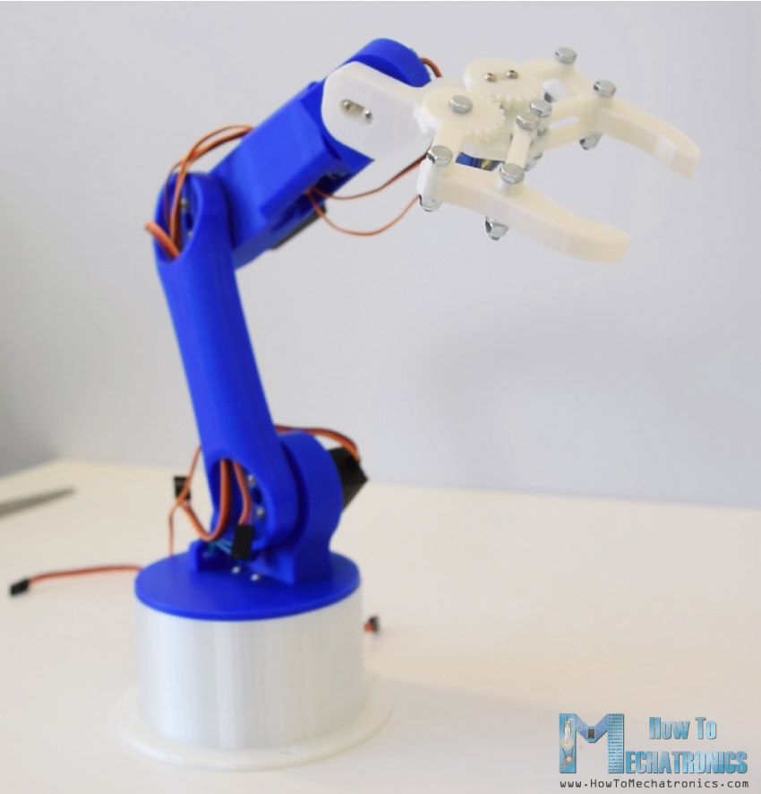
In this tutorial we will learn how to make an Arduino Robot Arm which can be wirelessly controlled and programmed using a custom-build Android application. I will show you the entire process of building it, starting from designing and 3D printing the robot parts, connecting the electronic components and programming the Arduino, to developing our own Android application for controlling the Robot Arm.
You can watch the following video or read the written tutorial below.
Overview
Using the sliders in the app we can manually control the movement of each servo or axis of the robot arm. Also using the “Save” button we can record each position or step and then the robot arm can automatically run and repeat these steps. With the same button we can pause the automatic operation as well as reset or delete all steps so that we can record new ones.
Arduino Robot Arm 3D Model
To begin with, I designed the Robot Arm using Solidworks 3D modeling software. The arm has 5 degrees of freedom.
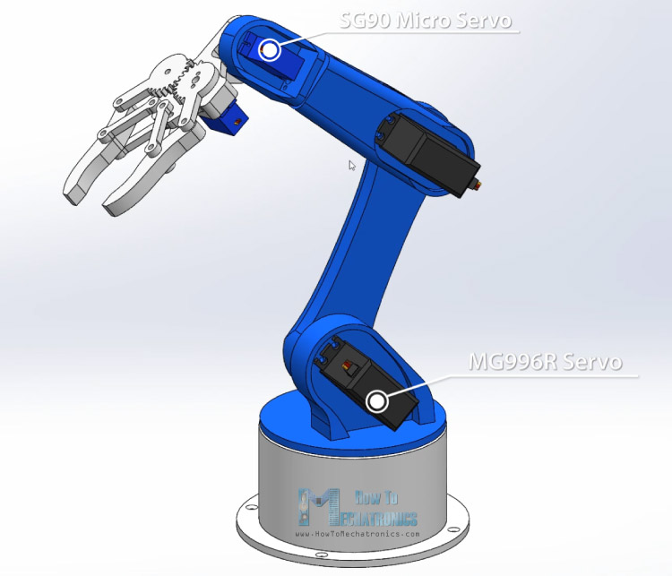
For the first 3 axis, the waist, the shoulder and the elbow, I used the MG996R servos, and for the other 2 axis, the wrist roll and wrist pitch, as well as the gripper I used the smaller SG90 micro servos.
You can get this 3D model, as well as the STL files for 3D Printing from Cults3D.
3D Printing the Robot Arm
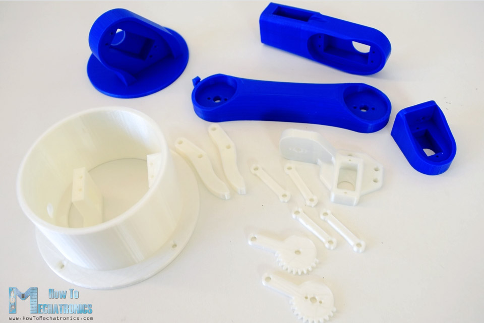
Using my new 3D Printer, Creality CR-10, I 3D printed all of the parts for the Arduino robot arm.
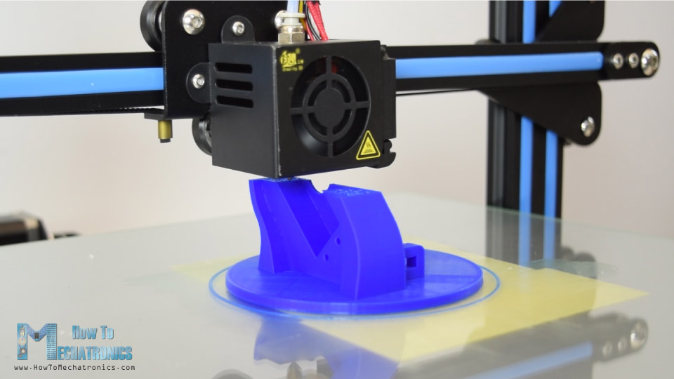
I had all of the parts for the Arduino Robot Arm ready in just several hours.
Read more: Top 15 Must-Have 3D Printer Accessories and Tools
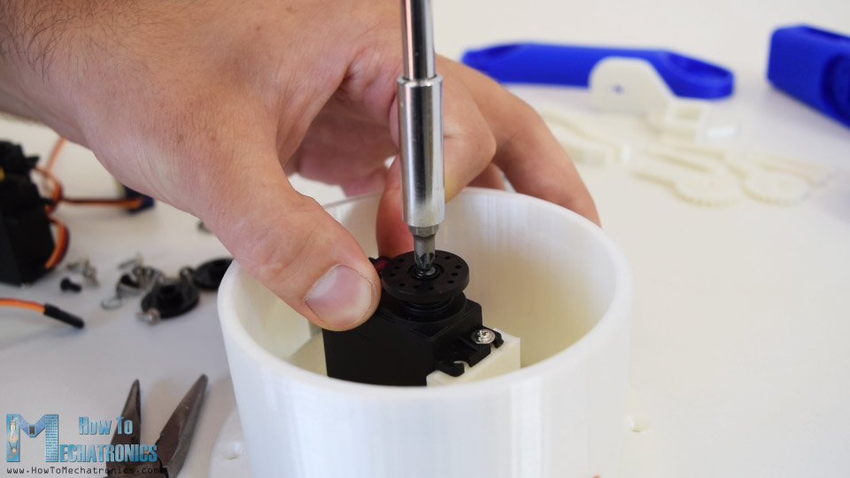
Assembling the Robot Arm
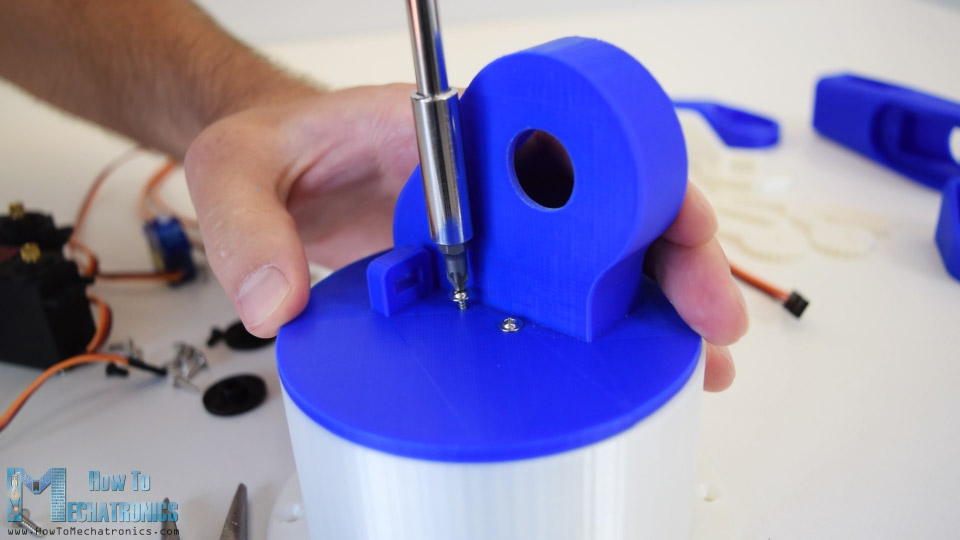
Ok, so at this point we are ready to assemble the robot arm. I started with the base on which I attached the first servo motor using the screws included in its package. Then on the output shaft of the servo I secured a round horn a bolt.
And on top of it I placed the upper part and secured it using two screws.
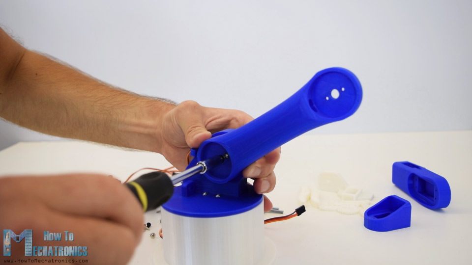
Here again first goes servo, then the round horn onto the next part, and then they are secured to each other using the bolt on the output shaft.
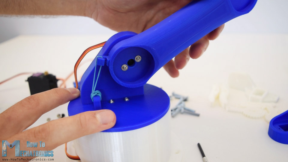
We can notice here that at the shoulder axis it is good idea to include some kind of spring or in my case I used a rubber band to give some help to the servo because this servo carries the whole weight of the rest of the arm as well as the payload.
In similar way I continued to assemble the rest of the robot arm. As for the gripper mechanism I used some 4 millimeters bolts and nuts to assembly it.
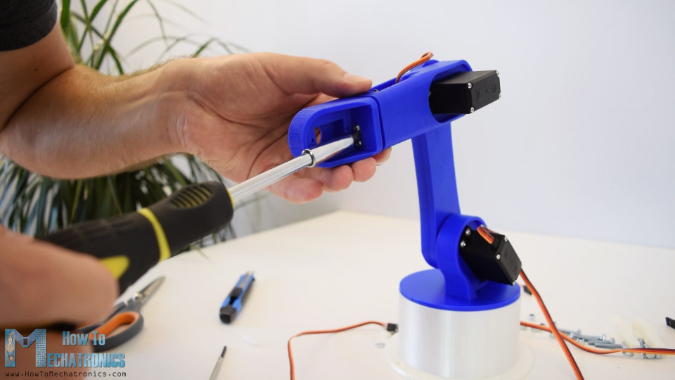
Finally I attached the gripper mechanism onto the last servo and the Arduino robot arm was completed.
Arduino Robot Arm Circuit Diagram
The next stage is connecting the electronics. The circuit diagram of this project is actually quite simple. We just need an Arduino board and a HC-05 Bluetooth module for communication with the smartphone. The control pins of the six servo motors are connected to six digital pins of the Arduino board.
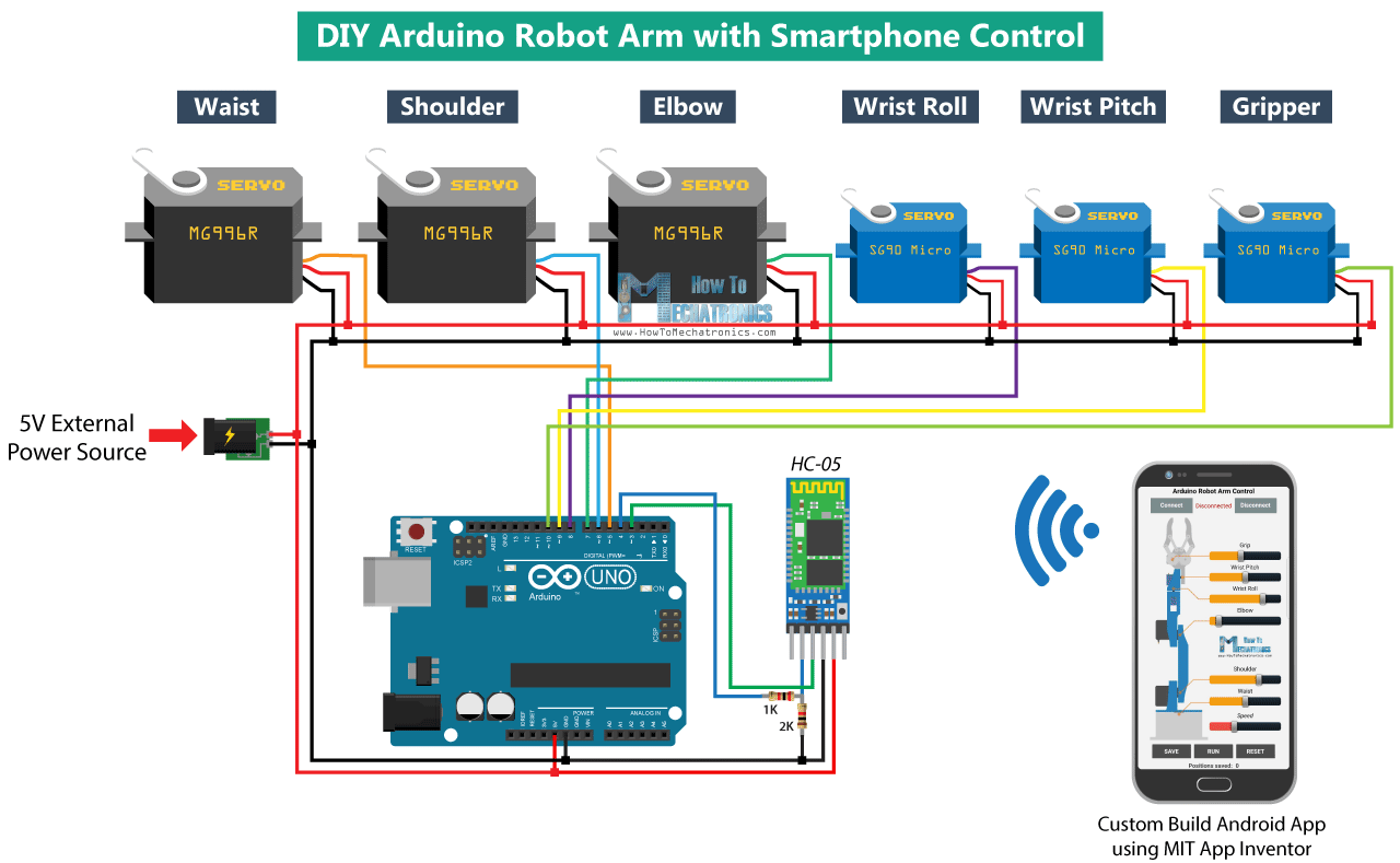
For powering the servos we need 5V, but this must come from an external power source because the Arduino is not able to handle the amount of current that all of them can draw. The power source must be able to handle at least 2A of current. So once we have connected everything together we can move on to programing the Arduino and make the Android app.
You can get the components needed for this example from the links below:
- MG996R Servo Motor……………………….…. Amazon / Banggood / AliExpress
- SG90 Micro Servo Motor ……..…….….……. Amazon / Banggood / AliExpress
- HC-05 Bluetooth Module ………………….… Amazon / Banggood / AliExpress
- Arduino Board ……………………………………. Amazon / Banggood / AliExpress
- 5V 2A DC Power Supply ………………….….. Amazon / Banggood / AliExpress
Disclosure: These are affiliate links. As an Amazon Associate I earn from qualifying purchases.
Arduino Robot Arm Code
As the code is a bit longer, for better understanding, I will post the source code of the program in sections with description for each section. And at the end of this article I will post the complete source code.
So first we need to include the SoftwareSerial library for the serial communication of the Bluetooth module as well as the servo library. Both of these libraries are included with the Arduino IDE so you don’t have to install them externally. Then we need to define the six servos, the HC-05 Bluetooth module and some variables for storing the current and previous position of the servos, as well as arrays for storing the positions or the steps for the automatic mode.
#include <SoftwareSerial.h>
#include <Servo.h>

Servo servo01;
Servo servo02;
Servo servo03;
Servo servo04;
Servo servo05;
Servo servo06;

SoftwareSerial Bluetooth(3, 4); // Arduino(RX, TX) - HC-05 Bluetooth (TX, RX)

int servo1Pos, servo2Pos, servo3Pos, servo4Pos, servo5Pos, servo6Pos; // current position
int servo1PPos, servo2PPos, servo3PPos, servo4PPos, servo5PPos, servo6PPos; // previous position
int servo01SP[50], servo02SP[50], servo03SP[50], servo04SP[50], servo05SP[50], servo06SP[50]; // for storing positions/steps
int speedDelay = 20;
int index = 0;
String dataIn = "";Code language: PHP (php)
In the setup section we need to initialize the servos and the Bluetooth module and move the robot arm to its initial position. We do that using the write() function which simply moves the servo to any position from 0 to 180 degrees.
void setup() {
  servo01.attach(5);
  servo02.attach(6);
  servo03.attach(7);
  servo04.attach(8);
  servo05.attach(9);
  servo06.attach(10);
  Bluetooth.begin(38400); // Default baud rate of the Bluetooth module
  Bluetooth.setTimeout(1);
  delay(20);
  // Robot arm initial position
  servo1PPos = 90;
  servo01.write(servo1PPos);
  servo2PPos = 150;
  servo02.write(servo2PPos);
  servo3PPos = 35;
  servo03.write(servo3PPos);
  servo4PPos = 140;
  servo04.write(servo4PPos);
  servo5PPos = 85;
  servo05.write(servo5PPos);
  servo6PPos = 80;
  servo06.write(servo6PPos);
}Code language: JavaScript (javascript)
Next, in the loop section, using the Bluetooth.available() function , we constantly check whether there is any incoming data from the Smartphone. If true, using the readString() function we read the data as string an store it into the dataIn variable. Depending on the arrived data we will tell robot arm what to do.
// Check for incoming data
  if (Bluetooth.available() > 0) {
    dataIn = Bluetooth.readString();  // Read the data as stringCode language: JavaScript (javascript)
Control Android App
Let’s take a look at the Android app now and see what kind of data it is actually sending to the Arduino.
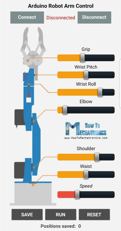
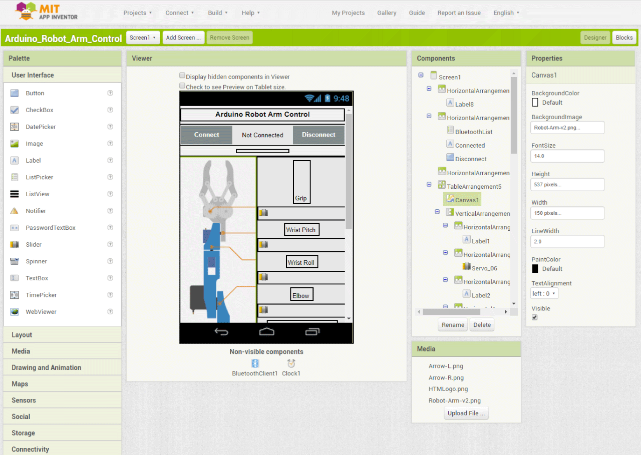
I made the app using the MIT App Inventor online application and here’s how it works. At the top we have two buttons for connecting the smartphone to the HC-05 Bluetooth module. Then on the left side we have an image of the robot arm, and on the right side we have the six slider for controlling the servos and one slider for the speed control.
Each slider have different initial, minimum and maximum value that suits the robot arm joints. At the bottom of the app, we have three button, SAVE, RUN and RESET through which we can program the robot arm to run automatically. There is also a label below which shows the number of steps we have saved. Nevertheless, for more details how to build apps like this using the MIT App Inventor you can check my other detailed tutorial for it.
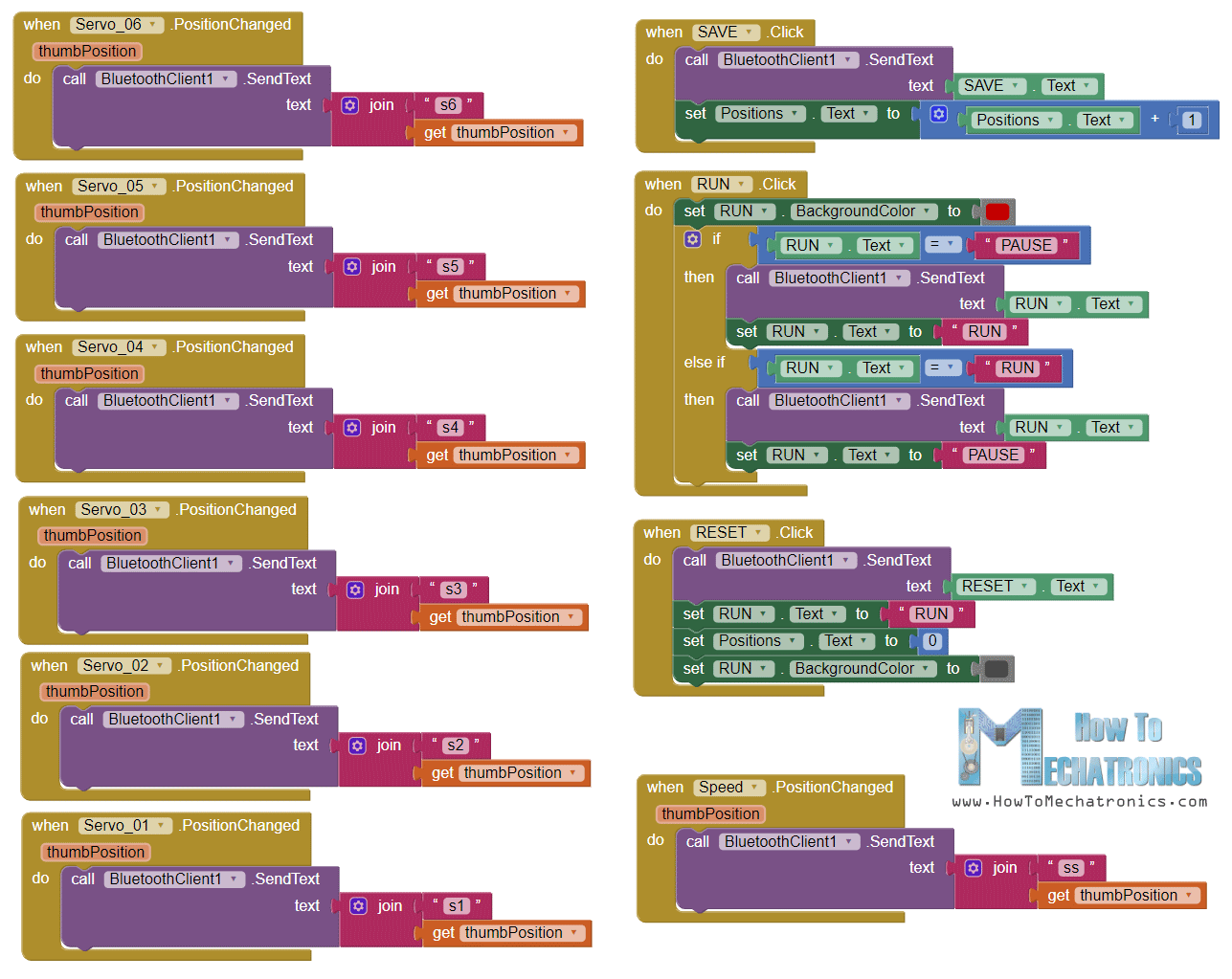
Ok, now let’s see the program or the blocks behind the application. First, on the left side we have the blocks for connecting the smartphone to the Bluetooth module.
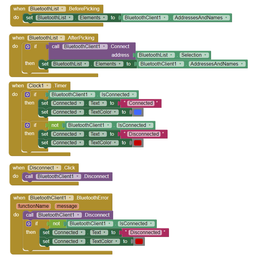
Then we have the sliders blocks for the servo position control and the buttons blocks for programing the robot arm. So if we change the position of the slider, using the Bluetooth function .SendText, we send a text to the Arduino. This text consist of a prefix which indicates which slider has been changed as well as the current value of the slider.
Here’s a download file of the above MIT App Inventor project, as well as the Android App ready to be installed on your smartphone:
So therefore, at the Arduino, using the startsWith() function we check the prefix of each incoming data and so we know what do to next. For example, if the prefix is “s1” we know that we need to move the servo number one. Using the substring() function we get the remaining text, or that’s the position value, we convert it into integer and use the value to move the servo to that position.
// If "Waist" slider has changed value - Move Servo 1 to position
    if (dataIn.startsWith("s1")) {
      String dataInS = dataIn.substring(2, dataIn.length()); // Extract only the number. E.g. from "s1120" to "120"
      servo1Pos = dataInS.toInt();  // Convert the string into integerCode language: JavaScript (javascript)
Here we can simply call the write() function and the servo will go to that position, but in that way the servo would run at its maximum speed which is too much for the robot arm. Instead we need to control the speed of the servos so I used some FOR loops in order to gradually move the servo from the previous to the current position by implementing a delay time between each iteration. By changing the delay time you can change the speed of the servo.
// We use for loops so we can control the speed of the servo
      // If previous position is bigger then current position
      if (servo1PPos > servo1Pos) {
        for ( int j = servo1PPos; j >= servo1Pos; j--) {   // Run servo down
          servo01.write(j);
          delay(20);    // defines the speed at which the servo rotates
        }
      }
      // If previous position is smaller then current position
      if (servo1PPos < servo1Pos) {
        for ( int j = servo1PPos; j <= servo1Pos; j++) {   // Run servo up
          servo01.write(j);
          delay(20);
        }
      }
      servo1PPos = servo1Pos;   // set current position as previous position
    }Code language: JavaScript (javascript)
The same method is used for driving each axis of the robot arm.
Below them is the SAVE button. If we press the SAVE button, the position of each servo motor is stored in an array. With each pressing the index increases so the array is filled step by step.
// If button "SAVE" is pressed
    if (dataIn.startsWith("SAVE")) {
      servo01SP[index] = servo1PPos;  // save position into the array
      servo02SP[index] = servo2PPos;
      servo03SP[index] = servo3PPos;
      servo04SP[index] = servo4PPos;
      servo05SP[index] = servo5PPos;
      servo06SP[index] = servo6PPos;
      index++;                        // Increase the array index
    }Code language: JavaScript (javascript)
Then if we press the RUN button we call the runservo() custom function which runs stored steps. Let’s take a look at this function. So here we run the stored steps over and over again until we press the RESET button. Using the FOR loop we run through all positions stored in the arrays and at the same time we check whether we have any incoming data from the smartphone. This data can be the RUN/PAUSE button, which pauses the robot, and if clicked again continues with the automatic movements. Also if we change the speed slider position, we will use that value to change the delay time between each iteration in the FOR loops below, which controls the speed of the servo motors.
// Automatic mode custom function - run the saved steps
void runservo() {
  while (dataIn != "RESET") {   // Run the steps over and over again until "RESET" button is pressed
    for (int i = 0; i <= index - 2; i++) {  // Run through all steps(index)
      if (Bluetooth.available() > 0) {      // Check for incomding data
        dataIn = Bluetooth.readString();
        if ( dataIn == "PAUSE") {           // If button "PAUSE" is pressed
          while (dataIn != "RUN") {         // Wait until "RUN" is pressed again
            if (Bluetooth.available() > 0) {
              dataIn = Bluetooth.readString();
              if ( dataIn == "RESET") {
                break;
              }
            }
          }
        }
        // If SPEED slider is changed
        if (dataIn.startsWith("ss")) {
          String dataInS = dataIn.substring(2, dataIn.length());
          speedDelay = dataInS.toInt(); // Change servo speed (delay time)
        }
      }
      // Servo 1
      if (servo01SP[i] == servo01SP[i + 1]) {
      }
      if (servo01SP[i] > servo01SP[i + 1]) {
        for ( int j = servo01SP[i]; j >= servo01SP[i + 1]; j--) {
          servo01.write(j);
          delay(speedDelay);
        }
      }
      if (servo01SP[i] < servo01SP[i + 1]) {
        for ( int j = servo01SP[i]; j <= servo01SP[i + 1]; j++) {
          servo01.write(j);
          delay(speedDelay);
        }
      }Code language: JavaScript (javascript)
In similar way as explained earlier with these IF statements and FOR loops we move the servos to their next position. Finally if we press the RESET button we will clear all the data from the arrays to zero and also reset the index to zero so we can reprogram the robot arm with new movements.
// If button "RESET" is pressed
    if ( dataIn == "RESET") {
      memset(servo01SP, 0, sizeof(servo01SP)); // Clear the array data to 0
      memset(servo02SP, 0, sizeof(servo02SP));
      memset(servo03SP, 0, sizeof(servo03SP));
      memset(servo04SP, 0, sizeof(servo04SP));
      memset(servo05SP, 0, sizeof(servo05SP));
      memset(servo06SP, 0, sizeof(servo06SP));
      index = 0;  // Index to 0
    }Code language: JavaScript (javascript)
And that’s it, now we can enjoy and have some fun with the robot arm.
Here’s the complete code of the Arduino Robot Arm:
/*
       DIY Arduino Robot Arm Smartphone Control
        by Dejan, www.HowToMechatronics.com
*/

#include <SoftwareSerial.h>
#include <Servo.h>

Servo servo01;
Servo servo02;
Servo servo03;
Servo servo04;
Servo servo05;
Servo servo06;

SoftwareSerial Bluetooth(3, 4); // Arduino(RX, TX) - HC-05 Bluetooth (TX, RX)

int servo1Pos, servo2Pos, servo3Pos, servo4Pos, servo5Pos, servo6Pos; // current position
int servo1PPos, servo2PPos, servo3PPos, servo4PPos, servo5PPos, servo6PPos; // previous position
int servo01SP[50], servo02SP[50], servo03SP[50], servo04SP[50], servo05SP[50], servo06SP[50]; // for storing positions/steps
int speedDelay = 20;
int index = 0;
String dataIn = "";

void setup() {
  servo01.attach(5);
  servo02.attach(6);
  servo03.attach(7);
  servo04.attach(8);
  servo05.attach(9);
  servo06.attach(10);
  Bluetooth.begin(38400); // Default baud rate of the Bluetooth module
  Bluetooth.setTimeout(1);
  delay(20);
  // Robot arm initial position
  servo1PPos = 90;
  servo01.write(servo1PPos);
  servo2PPos = 150;
  servo02.write(servo2PPos);
  servo3PPos = 35;
  servo03.write(servo3PPos);
  servo4PPos = 140;
  servo04.write(servo4PPos);
  servo5PPos = 85;
  servo05.write(servo5PPos);
  servo6PPos = 80;
  servo06.write(servo6PPos);
}

void loop() {
  // Check for incoming data
  if (Bluetooth.available() > 0) {
    dataIn = Bluetooth.readString();  // Read the data as string

    // If "Waist" slider has changed value - Move Servo 1 to position
    if (dataIn.startsWith("s1")) {
      String dataInS = dataIn.substring(2, dataIn.length()); // Extract only the number. E.g. from "s1120" to "120"
      servo1Pos = dataInS.toInt();  // Convert the string into integer
      // We use for loops so we can control the speed of the servo
      // If previous position is bigger then current position
      if (servo1PPos > servo1Pos) {
        for ( int j = servo1PPos; j >= servo1Pos; j--) {   // Run servo down
          servo01.write(j);
          delay(20);    // defines the speed at which the servo rotates
        }
      }
      // If previous position is smaller then current position
      if (servo1PPos < servo1Pos) {
        for ( int j = servo1PPos; j <= servo1Pos; j++) {   // Run servo up
          servo01.write(j);
          delay(20);
        }
      }
      servo1PPos = servo1Pos;   // set current position as previous position
    }

    // Move Servo 2
    if (dataIn.startsWith("s2")) {
      String dataInS = dataIn.substring(2, dataIn.length());
      servo2Pos = dataInS.toInt();

      if (servo2PPos > servo2Pos) {
        for ( int j = servo2PPos; j >= servo2Pos; j--) {
          servo02.write(j);
          delay(50);
        }
      }
      if (servo2PPos < servo2Pos) {
        for ( int j = servo2PPos; j <= servo2Pos; j++) {
          servo02.write(j);
          delay(50);
        }
      }
      servo2PPos = servo2Pos;
    }
    // Move Servo 3
    if (dataIn.startsWith("s3")) {
      String dataInS = dataIn.substring(2, dataIn.length());
      servo3Pos = dataInS.toInt();
      if (servo3PPos > servo3Pos) {
        for ( int j = servo3PPos; j >= servo3Pos; j--) {
          servo03.write(j);
          delay(30);
        }
      }
      if (servo3PPos < servo3Pos) {
        for ( int j = servo3PPos; j <= servo3Pos; j++) {
          servo03.write(j);
          delay(30);
        }
      }
      servo3PPos = servo3Pos;
    }
    // Move Servo 4
    if (dataIn.startsWith("s4")) {
      String dataInS = dataIn.substring(2, dataIn.length());
      servo4Pos = dataInS.toInt();
      if (servo4PPos > servo4Pos) {
        for ( int j = servo4PPos; j >= servo4Pos; j--) {
          servo04.write(j);
          delay(30);
        }
      }
      if (servo4PPos < servo4Pos) {
        for ( int j = servo4PPos; j <= servo4Pos; j++) {
          servo04.write(j);
          delay(30);
        }
      }
      servo4PPos = servo4Pos;
    }
    // Move Servo 5
    if (dataIn.startsWith("s5")) {
      String dataInS = dataIn.substring(2, dataIn.length());
      servo5Pos = dataInS.toInt();
      if (servo5PPos > servo5Pos) {
        for ( int j = servo5PPos; j >= servo5Pos; j--) {
          servo05.write(j);
          delay(30);
        }
      }
      if (servo5PPos < servo5Pos) {
        for ( int j = servo5PPos; j <= servo5Pos; j++) {
          servo05.write(j);
          delay(30);
        }
      }
      servo5PPos = servo5Pos;
    }
    // Move Servo 6
    if (dataIn.startsWith("s6")) {
      String dataInS = dataIn.substring(2, dataIn.length());
      servo6Pos = dataInS.toInt();
      if (servo6PPos > servo6Pos) {
        for ( int j = servo6PPos; j >= servo6Pos; j--) {
          servo06.write(j);
          delay(30);
        }
      }
      if (servo6PPos < servo6Pos) {
        for ( int j = servo6PPos; j <= servo6Pos; j++) {
          servo06.write(j);
          delay(30);
        }
      }
      servo6PPos = servo6Pos;
    }
    // If button "SAVE" is pressed
    if (dataIn.startsWith("SAVE")) {
      servo01SP[index] = servo1PPos;  // save position into the array
      servo02SP[index] = servo2PPos;
      servo03SP[index] = servo3PPos;
      servo04SP[index] = servo4PPos;
      servo05SP[index] = servo5PPos;
      servo06SP[index] = servo6PPos;
      index++;                        // Increase the array index
    }
    // If button "RUN" is pressed
    if (dataIn.startsWith("RUN")) {
      runservo();  // Automatic mode - run the saved steps
    }
    // If button "RESET" is pressed
    if ( dataIn == "RESET") {
      memset(servo01SP, 0, sizeof(servo01SP)); // Clear the array data to 0
      memset(servo02SP, 0, sizeof(servo02SP));
      memset(servo03SP, 0, sizeof(servo03SP));
      memset(servo04SP, 0, sizeof(servo04SP));
      memset(servo05SP, 0, sizeof(servo05SP));
      memset(servo06SP, 0, sizeof(servo06SP));
      index = 0;  // Index to 0
    }
  }
}

// Automatic mode custom function - run the saved steps
void runservo() {
  while (dataIn != "RESET") {   // Run the steps over and over again until "RESET" button is pressed
    for (int i = 0; i <= index - 2; i++) {  // Run through all steps(index)
      if (Bluetooth.available() > 0) {      // Check for incomding data
        dataIn = Bluetooth.readString();
        if ( dataIn == "PAUSE") {           // If button "PAUSE" is pressed
          while (dataIn != "RUN") {         // Wait until "RUN" is pressed again
            if (Bluetooth.available() > 0) {
              dataIn = Bluetooth.readString();
              if ( dataIn == "RESET") {
                break;
              }
            }
          }
        }
        // If speed slider is changed
        if (dataIn.startsWith("ss")) {
          String dataInS = dataIn.substring(2, dataIn.length());
          speedDelay = dataInS.toInt(); // Change servo speed (delay time)
        }
      }
      // Servo 1
      if (servo01SP[i] == servo01SP[i + 1]) {
      }
      if (servo01SP[i] > servo01SP[i + 1]) {
        for ( int j = servo01SP[i]; j >= servo01SP[i + 1]; j--) {
          servo01.write(j);
          delay(speedDelay);
        }
      }
      if (servo01SP[i] < servo01SP[i + 1]) {
        for ( int j = servo01SP[i]; j <= servo01SP[i + 1]; j++) {
          servo01.write(j);
          delay(speedDelay);
        }
      }

      // Servo 2
      if (servo02SP[i] == servo02SP[i + 1]) {
      }
      if (servo02SP[i] > servo02SP[i + 1]) {
        for ( int j = servo02SP[i]; j >= servo02SP[i + 1]; j--) {
          servo02.write(j);
          delay(speedDelay);
        }
      }
      if (servo02SP[i] < servo02SP[i + 1]) {
        for ( int j = servo02SP[i]; j <= servo02SP[i + 1]; j++) {
          servo02.write(j);
          delay(speedDelay);
        }
      }

      // Servo 3
      if (servo03SP[i] == servo03SP[i + 1]) {
      }
      if (servo03SP[i] > servo03SP[i + 1]) {
        for ( int j = servo03SP[i]; j >= servo03SP[i + 1]; j--) {
          servo03.write(j);
          delay(speedDelay);
        }
      }
      if (servo03SP[i] < servo03SP[i + 1]) {
        for ( int j = servo03SP[i]; j <= servo03SP[i + 1]; j++) {
          servo03.write(j);
          delay(speedDelay);
        }
      }

      // Servo 4
      if (servo04SP[i] == servo04SP[i + 1]) {
      }
      if (servo04SP[i] > servo04SP[i + 1]) {
        for ( int j = servo04SP[i]; j >= servo04SP[i + 1]; j--) {
          servo04.write(j);
          delay(speedDelay);
        }
      }
      if (servo04SP[i] < servo04SP[i + 1]) {
        for ( int j = servo04SP[i]; j <= servo04SP[i + 1]; j++) {
          servo04.write(j);
          delay(speedDelay);
        }
      }

      // Servo 5
      if (servo05SP[i] == servo05SP[i + 1]) {
      }
      if (servo05SP[i] > servo05SP[i + 1]) {
        for ( int j = servo05SP[i]; j >= servo05SP[i + 1]; j--) {
          servo05.write(j);
          delay(speedDelay);
        }
      }
      if (servo05SP[i] < servo05SP[i + 1]) {
        for ( int j = servo05SP[i]; j <= servo05SP[i + 1]; j++) {
          servo05.write(j);
          delay(speedDelay);
        }
      }

      // Servo 6
      if (servo06SP[i] == servo06SP[i + 1]) {
      }
      if (servo06SP[i] > servo06SP[i + 1]) {
        for ( int j = servo06SP[i]; j >= servo06SP[i + 1]; j--) {
          servo06.write(j);
          delay(speedDelay);
        }
      }
      if (servo06SP[i] < servo06SP[i + 1]) {
        for ( int j = servo06SP[i]; j <= servo06SP[i + 1]; j++) {
          servo06.write(j);
          delay(speedDelay);
        }
      }
    }
  }
}Code language: PHP (php)
I hope you liked this video and learned something new. Feel free to ask any question in the comments section below and check my Arduino Projects Collection.
Hi there! I was wondering if it’s possible to control this robotic arm using one or two joysticks and an Arduino board. I have an Arduino R4 WiFi. If so, could you please give me some advice on how to set it up? Thank you!
Hey, sure that’s possible. But it’s a completely different interface I couldn’t help you like this. There are tutorials out there for most of them.
Cheers
I am building this with my son. The 3D parts are very well designed. We deeply appreciate all of the time and effort you put into creating this. It has been a super fun and rewarding learning experience. Thank you very much!
So glad to hear it, cheers!
Thank you very much. Very nice project and everything works correctly.
https://youtu.be/eTVZzaECulI
That’s great, glad to see it working properly!
Hello.
I have to admit this is an amazing project that I plan on building together with my son. I have ordered a Creality Ender 3 v2 printer. The maximum print size is around 22 cubic cm. Could you please let me know (as I do not yet have the printer) what is the maximum size of the components for this project?
Also, one more question: as I am not an expert in designing circuits, do you think it would be possible to use an external battery (max output 5V, 2.4A) to power this circuit? I would appreciate some more details on the wiring, if possible.
Thanks in advance and thanks for the great work!
Hey, thanks and have fun building one! The arm parts not that big, they will all fit on the ender 3. For powering the robot you need 5V with around 2-3A, so I guess a battery of 5V and 2.4A will be enough. The wiring is simple, just follow the circuit diagram provided in the article and you should be fine. Cheers!
Hello, Dejan, I am done 🙂
https://www.youtube.com/watch?v=WhS32PAQDRA&t=308s&ab_channel=sykyondra
I used this to clean up the string data and it seems to help servo movement. Basically this code finds the the decimal and deletes it plus everything after.
//clean up string
if(dataIn.startsWith(“s”))
{
//look for the decimal
for(int i = 2; i < dataIn.length(); i++)
{
//if decimal found…
if(dataIn.charAt(i) == '.')
{
//remove decimal plus everything after
dataIn.remove(i); //this cleans up string
break;
}
}
}
HI. Thanks for sharing.
Where did you insert this code to clean up the string data?
Thanks!
Good day, excellent project.
What settings did you use when printing the parts, i.e. layer height, temp of nozzle etc.?
Thanks! Well the settings depend on the printer itself and the material your are using, as well as how fine you like the parts to come out. I used 0.2mm layer height and 200 degrees nozzle tepm for a normal PLA material.
Hi Dejan,
Thank you for the reply, I ended up using white PLA with a layer height of 0.16 mm. Printing is almost complete and eager to finish the project.
Hello Mr.Dejan,
Great project! I use your projects to teach kids about arduino / coding.
Quick comments:
– An issue I was having with the slider and Bluetooth – incomplete data was being received and it caused un-expected behavior. I modified the code with the “processSerial()” function from this article – https://forum.arduino.cc/index.php?topic=233092.0 and modified the MIT app – joined a new string with “\r” for each command sent. This combo worked perfectly.
– I used your control app and code from the Mecannum wheels app for better control of the arm. This approach worked without modification.
One issue I am still having is that the MG996R servos sometimes go off into an uncontrollable spin!! This is quite random – no particular order. I have tried quite hard – but could not find a solution. Any advice would be really helpful.
THANK You again for all your projects. The kids are learning a lot from this.
-Chris
Thanks for the great project! Fun design and also a great learning experience! I also had the same issue of the servos reacting strange.
Solution I found:
Change baud rate to 9600.
Added Serial.print (dataIn); to watch the data. This is where I saw the strings being sent were random.
Changed the phone app for the string generation. Instead of using “get Thumb Position”, I used “round” and “Servo_0#, Thumb Position”. The round function sends only a whole number and eliminates a ton of communication between the BT module and Arduino.
Hope this helps everyone!
Update: I found I was still getting strings which were broken or incomplete. By removing two lines from the Arduino code, testing appears to be working great so far.
//bluetooth.setTimeout(1);
//delay(20);
Nice to hear you found the project interesting.
Thanks for the input!
Hello,
Finally , used the code and app from” Arduino Robot Arm and Mecanum Wheels” , change the code by removing the parts for the stepper,change the SoftSerial to NeoSWSerial (on pin 8,9) , and used a logic level shifter between RX/TX bluetooth and the arduino NANO, for the HC-05 I used the JDY-31-SPP.
also change the app (with MIT), and remove the parts belonging to the steppers, also added a “HOME” button, when activated all servos go to the initial position.
finally is working correctly, the only (maybe) needed performance change could be the save and run… (not always correct programmed).
For me It was / is a VERY GOOD project, a lot of things are becoming more clear, have also some new programming experience.
only it was (for me) a little-bit missing the goal, the Idea was to do it with my grandson…, but for me it was already not so easy, so much to complicated for a (clever) child of 9 years!
never less thanks for the nice project and sharing all necessary files and information
Hello,
I solved the high unstable when using the silders, by using the normal RX TX (and no softserial), by the UNO.
but i will use a NANO, and my cheap clone was not able to work (interaction witch the CH340 on board), I solved this as followed:
1- go back to softserial, by now using NeoSWSerial
2- changed port 8 to 11 , 9 to 12
3- the port 8 and 9 now used for the NeoSWSerial.
final the Robot arm is working nice!
comment, first I try to use “AltsoftSerial ” (instead of softserial) , but i’m then facing with upload issue, because there is a error with the servo library??
Best regards , Wim
Hi. Can you please be more specific? I am having serious problems when trying to operate the arm.It just goes crazy when I try to move a servo. I use Arduino Uno. If I connect RX and TX to 0 and 1, what should I use instead of this command: “SoftwareSerial Bluetooth(3, 4);”? How should these RX and TX pins be defined? What library should i use to define the bluetooth variable?Please help me.
forgotten to say, i could not buy the HC 05, instead I buyed the JDY-31-spp (should be compatible?)
Thanks for your reaction!, I already i’m a lot further, most improvement was to use a level shifter instead the resistors, furthermore change speed to 9600, Now it is working with “tipping” the sliders, by “sliding”everything becomes unstable, I also think the (very) cheap servo’s are not helping, changed one of the most unstable servo’s was also helping.
the big servo are taken a lot of current, by the thin wires, maybe the supply voltage of the servos is to low.
checked the signals to servo’s with scoop, by unstable also here some action…..
the RX TX signals are now stable (with levelshifter!)
You have a GREAT site, with a lot off new idears with will activate your motivation and inventiveness, now I understand the codings are not “ready to use” but must be optimized for your own configuration.
Yesterday I was just disappointing (special for my grandson 9 years) .
a solution for the “old app”, is just to renew it with the Mit software (load and save..)
Hello there,
I printed and build your “robot arm”, unfortunately i’m facing some problems
1- the app form ardroid, gives the warning to old maby not compatible
2- after final build, all servos’s go to home position, but when i try to move everything is oscillating and bad moving, when i change the baudrate to 9600, is is a litte better, but still not workable.
3- Do you have maybe a idea to improve? now , a lot of work, but not nice working, my skills for programming are not so High, but mechanical and electronic I have a good skill, your help shall be much appropriated
Best regards Wim
I made the whole robot arm design and I am having issues with the bluetooth connecton. I can connect to the HC-05 with the app but it does nothing. Are resistors required for the RX pin in order for it to work? That is what I don’t currently have because the HC-05 handles from 3.6-6v. Do you think that is the reason for it not working? I have seen some people use resistors, and others don’t so I’m confused. I tried turning on the LED from pin 13 via an app and that doesn’t work either. I have tried serial bluetooth monitor apps and I am receiving no data from the module. I know everything is connected properly. Could it just be defective or would the resistors make it work? Any help would be greatly appreciated. Thanks!
Hey, well the missing resistors might be the problem. The HC-05 module works from 3.6 -6V, but the TX logic pin work at 3.3v. All sources are stating that. So the point of the resistors is to drop the 5V coming from the Arduino RX pin, to 3.3V so the Bluetooth module can accept it. I haven’t test the module whether it works the way you connected, without the voltage divider, so I could tell you for sure whether that’s the problem, but you should definitely try to change that. Also make sure the baud rate is set properly.
Hi!
This web site is very useful.
I built a robotic arm but I bought the Elegoo Mega 2560, so I use pin 0 and 1 (RX/TX) with the Hc-05 Bluetooth module. It’s connected to my application (MIT app inventor).
But, when I try to control the robot with the application, nothing is happening. The robotic arm don’t move.
I read the previous comments and when I change my code, nothing is happening too.
Can you help me please?
Thank?
Hey, thanks! Try to use different pins for the Bluetooth module. Also try some of the other basic examples from my dedicated Arduino Bluetooth tutorial to make sure you know how to connect it and you can establish the communication. Then get back to this project and make sure you have proper commutation first, try to see what are you getting from the smartphone app by printing the data on the serial monitor.
Hi
Thanks!
I have many problems to build it but the “Arduino Robot Arm and Mecanum Wheels.” Project: Code And App
help very much…
Now this work perfectly!
Yeah, for anyone having trouble with this code and app, you should definitely check the code and app from that project, “Arduino Robot Arm and Mecanum Wheels”. In that project I updated the code and the app, the control is a bit different and works better.
TO: Siim March 11, 2020
Hi , are you willing to share your “new”code and app? , I also facing some problems, solved the comunication with a level shifter, and use neoSWSerial instead of software serial.
but now saving position is Not working correctly, So I think also to use the other code, but my program skils are not so high:)
Wim
Hi! Love the website and the arm project so far.
I am connecting all the wires and wanted to know if you can provide a breadboard view diagram? I am still new at translating a wiring diagram to how everything connects on a bread board.
Thanks!
Hey, thanks! I’m sorry but I don’t have a breadboard diagram to share it. However, it should be easy to connect everything through a breadboard, you just have to follow all of the connections.
Hi, thanks for the project! There is a problem. Servomotors do not move. Tried to come up with something that gets the Arduino via Bluetooth, to the console. In the end, there is a lot “???xxx ” in different order, how can this be solved? I apologize for my English.
Hey, the problem is the communication. Make sure you have set the correct baud rate in the program that matches with your Bluetooth module baud rate. To be honest, this code and the Android app don’t work very well. I made an updated version of the robot arm in my Arduino Robot Arm and Mecanum Wheels Platform project, where I use different approach to control the arm. I already said I will upgrade this article with the new updated version, but I still haven’t done that. Hopefully I will do that soon.
I want to do the Arduino robot arm project that you did in your video. Although I don’t want to use the micro servos and instead want to use 6 MG996R servos instead. I was wondering if you could send me a 3D model of it with the parts with the bigger servos than the micro ones. I am unable to do it myself because I am new 3D modeling and can’t figure out how to do it.
I’d appreciate if you could reply to me as soon as possible.
Hey, sorry but I don’t have such a model.
HI
I am having trouble connecting the circuit with the breadboard. Can you provide the schematics for the breadboard connections?
Also, how to connect the 5V 2A power supply with all the Servos?
Please help, I am doing this as a school project.
Hey, you just have to follow the circuit diagram and connect everything together through the breadboard. The same applies for the power supply.
Instead of having a continuous input, perhaps the slider values should be categorized into small ‘bins’. So for a range of 0-100 for the slider, we can have 50 different categories which can be mapped to the servo output. I am facing the same issues with the slider and thinking if this solution could work. Will try to implement and post again.
Hi Dejan. I like your project very much and I have just completed building one.:) I am not so sure.
I am now troubleshooting which part of the arm(or servo) may cause jerky movement. I did this by disabling (pulling out the ground wire) for five servos, hence, say, leaving only the Elbow servo on.
Elbow servo/joint is fine when i slide the slider. However, when i slide the other sliders which are off, this caused the arm to jerk. Any other things I can try?
For your further information, I am using Arduino uno and I don’t use the round hones. instead used the ones that comes with the servo. and I used super glue to secure them to the flat surface of each arm.
Thank you very much in advance for your help.
Thank you. Kevin Gee
Hey, the problem is in the program or the communication between the Android app and the Arduino. Check out my other project, Arduino Robot Arm and Mecanum Wheels. Here I used different approach for controlling the servos which doesn’t cause this problem.
Hello,
It’s a really impressive project. I would like to make a bigger version of the same robot. My aim is the exact same robot but maybe 2 or 3 times bigger. So for that should I use different servo motors?
I have a few more questions, if possible can we have a conversation through email. It would be of great help.
Hey, thanks!
Well yeah, you definitely need to use different servo motors. These servo motors wound not have enough power to deal with the weight of the bigger parts. Stepper motors would be more appropriate for bigger version, but that would be a whole different project in terms of the program as well as design.
Hi,thanks for all your help and good job man.I have a question.I live in Iran.looks like in here we got 3 version of mg996r. 90,180 and 360 degree.which of those I should buy for these project?
Thanks and best of regards to you.
Hey, these are 180 degrees servos.
Dejan,
I am having trouble with moving the servos. I have everything connected as shown in diagram and I tried changing the baud rate to 9600 but still no luck with moving the servos. I am using the arduino mega 2560 and the HC-05 bluetooth module. Any idea what the issue could be?
How did you fix the circular servo horns issue?
Dejan,
Where did you get the circular servo horns that you used? The horns that came with the servos you linked do not fit the robot…
Same problem for me as well
Hi Dejan,
First of all, thank you very much for all your tutorials and projects! very inspirational!
I’m currently doing this robot arm and am getting this Error 516:Unable to write:broken pipe as well. All connections are done based on the wiring diagram. I’ve read about using the serial monitor. Do you have a tutorial for that? I have very limited knowledge on programming now. Am still learning.
But would like to check with you if the 5v power. Should i connect straight into the arduino uno socket? and have another 5v external to the servos.
Thank you very much!
Hey, you problem is that the Bluetooth communication for sure. You should find a what’s causing the problem. Try to make the examples from some of my other Arduino Bluetooth tutorials.
Are the servos accurate enough to try applying inverse kinematics?
No, definitely not accurate enough for such a purpose.
When will you update the Arduino code and the new app for this project?
any update on this?
thanks!
Hey, sorry I’m a bit busy this period and I still haven’t updated the article with the new app and Arduino code. I will do that soon!
What layer height and infill % were the parts printed at?
I used 0.2mm layer height and I think a 15% infill. But these values are not strict at all.
Ok and did you use supports for Arm 2 V3?
Hi~ i used a 6V 2A power supply, everything seems working fine, but everytime adjust the sliders in the app, all servos just shaken for like 1/20 of a second or less. wonder why..PLZ
Hey, check whether you are getting correct data from the phone by simply printing them on the serial monitor. Also when moving the sliders try to click on them instead of sliding them.
Hello Mr Dejan,
I’m still working on this project, and I was wondering which specific bolts and or screws (i.e. what sizes) I should use for each part…
Thank you,
Jessie
Hi. I really liked your project . But I can not understand only one why if the correct Assembly of electrical diagrams and download the code the servos twitch a little and if the motion of one servo the rest twitch also ?
The problem is that these cheap servos are not good enough or they are at their limit of moving the “heavy” parts. Also when using the app, try to click the sliders to the desired position, instead of sliding the slider.
Hello there. the project was very nice. I hope the 5v 3a adapter won’t be a nuisance to use. thank you.
Hey, thanks! 5V 3A adapter is fine.
Okay, I’ll still give it a try though because the project seems really cool.
My laptop is just a normal Macbook air and since I don’t have much space on my laptop, I don’t have many apps downloaded and I can’t seem to open the
Arduino Robot Arm 3D Model Solidworks Files, Arduino Robot Arm 3D Model STEP File, Arduino Robot Arm STL Files
you have. I had wanted to open them on my laptop so I might be able to edit them a bit on my Fusion 360 etc, though—are there other files you could provide me?
Thank you so much!
Are we required to connect resistors
You only need resistors for the Bluetooth receive pin. It supports only 3.3V, so therefore you need two resistors, 1k and 2k, or 10k and 20k, to make a voltage divider that drops the 5V from the Arduino to 3.3V for the Bluetooth RX pin.
Sir, I did not use any resistors for voltage dividing and still can get the correct command when I check through the Arduino serial monitor. The only thing I change is the Bluetooth default speed from 38400 to 9600, however, the Arm is not responsive to these commands. What could be the problem? I am not using any external voltage, could that be the problem? And one more thing, the arm just moves back and forth when I connect one motor at a time, I guess 90 degrees. Every motor does the same thing when I connect them one at a time.
Almost forgot to thank you for such a marvelous project, I mean it is so modular and well-written that it can be molded to any application. BUT only condition to the above problem 😉 Thanks
You must use external 5V power supply for powering this project. The MG996R servos are power hunger, the Arduino itself cannot supply enough current to them.
Thank you so much for posting this project!
I was thinking of doing this for a 1.5 months long project—I’m quite a beginner, so do you think that’s enough time for me to finish this (or more than enough time) or would it be a bit challenging?
Hey, I’m not quite sure about that. 🙂 It might be challenging because I’ve noticed many people have trouble getting smooth movements. I guess that’s because the servos are at their limit of lifting the weights of the arm. There’s also another thing people often find hard, to get the Bluetooth communication right. I mean, everything is already explained well, if not here, on some of my other tutorials for sure, but still is up to you decide whether you can do this project. 🙂
Okay, I’ll still give it a try thought because the project seems really cool.
My laptop is just a normal Macbook air and since I don’t have much space on my laptop, I don’t have many apps downloaded and I can’t seem to open the
Arduino Robot Arm 3D Model Solidworks Files, Arduino Robot Arm 3D Model STEP File, Arduino Robot Arm STL Files
you have. I had wanted to open them on my laptop so I might be able to edit them a bit on my Fusion 360 etc, though—are there other files you could provide me?
Thank you so much!
Hello Mr Dejan,
I was wondering if it was kind of rude of me to ask you for CAD files rather than the STL/STEP files you have made available for us? However, our teacher has made it clear that he needs a bit more original work (meaning I can’t just do everything you say here) so I was thinking of requesting you for the CAD files. If that is too much of a bother, though, please let me know. 🙂 Thank you!
Hey, the CAD files are already provided. There are Solidworks files as well as STEP file which can be opened with Fusion 360. You can open these files and modify them if you need that.
Hello,
Great Project. Do you know the approximate weight of the entire arm? I am trying to calculate the cost of printing this at my school.
Hey, thanks! Well according to Cura, it weights around 230g, with around 18h printing time for all parts.
Hi Dejan!
I am trying to make this project but I think I have a problem with my MG996R motors because the one that I bought are continuous motors. I want to ask you if the MG996R motors that you use are the same.
Hey, the MG996R is not a continuous servo, it’s 180 degrees servo.
Hello, I loved this project! I have one question. What kind of screws did you use? I want to know every type please, I have to buy all of them. Thanks!!!
Hey, the screws are the one included with the servo as accessories, they are like 2.5 or 3mm self-tapping screws. And as for the gripper, I used M4x20 bolts and nuts, although the holes for it in the design are 3mm (I expanded the holes to 4mm using a drill). So you can use M3 bolts for the gripper as well.
Hey Dejan! First of all, great project!
I wanted to tell you something. I’ve been building this project but I’ve been having problems with controlling the servo’s via the Android Application. I connected everything correctly etc, but the servo’s just didn’t want to move correctly. They either all moved, stuttered or not moved at all.
I found out that what’s causing this is the SoftwareSerial-library. It’s actually a very inefficient library for communication. All my problems where INSTANTLY solved by using an Arduino Mega, connecting the BT Module directly to a hardware serial port (Serial3 in my case) and not using SoftSerial at all.
So it might be worth mentioning here for people who are facing the same problem(s) 😉
Hey Mark, thanks for the input!
HELP PLEASE!!!
I connected everything correctly etc, but the servo’s just didn’t want to move correctly. They either all moved, stuttered or not moved at all.
USE ARDUINO UNO
Thanks
Hey, you have problem with the communication, you are not receiving the correct commands from the Android app. Try to use the Serial.print function and the serial monitor to check what kind of data you are getting from the App when you slide sliders. Also I would suggest to check my other project, Arduino Robot Arm and Mecanum Wheels, where I used a different method for controlling the robot arm.
Hello Mark,
can you explain how you did this in detail. I just built this Project too and I have the same problems.
Which pins on the Arduino Mega did you use and which code lines have to be changend?
How to power 6 servo motor with 2.5A stall current each? Won’t the jump wire/ breadboard burnt with 15A (6×2.5A) current? I tried to power a mg996r with 700mA, the servo didn’t rotate at all.😭 wanna try out the project🙏
Yeah, it’s true, 2.5A for a jump wire is too much. Why doesn’t the MG996R rotate at all? Is it shaky or not moving at all?
The motor not moving at all, but only with some noise. The try both pwm code & servo motor library code. It seem 700 mA is too low for a motor😭 how can I solve it. There are so much current needed.
Hi!
Indeed, jumper wires are not suited for such currents. You’ll need to use thicker cables. You’ll also need a component that will convert your input voltage/current to your desired/need voltage/current. This can be achieved with a step-up/step-down converter. In my case I used a Polulu 5V Step-Down converter. This component converts my 12V lipo battery input to a constant 5V with an available current of 5 – 32A (20A constant, 32A peak). Another advantage of this converter is that it will divide your required current by 2, lowering the required power supply/battery.
Example:
Current needed = 10A
Current actually being drawn from battery/power source = 5A
I used a 12V 2200mah lipo battery, which can deliver 44A of current at peak. But it will run out of charge very quickly. So a converter will also safe battery life and/or make it possible to use less powerful power supplies.
I’m running all servo’s using this lipo battery, the converter and a handmade ‘mounting rail’. Here you can see a picture of the rail I’ve made:
https://imgur.com/a/EatfJMm
Don’t look at the red, black and yellow cables, I’m also connecting sensors and motors to this project. The long pcb-type rail is what I’ve used, I soldered 2 lines (VCC and GND) to 6 pin headers. You can plug-in the servo cables to those pin headers. For the sensor(PWM) cables I soldered a direct line from the far left header pin directly to some blue wires. These blue wires are each connected to one PWN port on the Arduino.
I hope this helps with getting your own robot arm to work! Make sure to read up on converters on the internet and not just buy one. The Chinese ones are not as powerful as they often advertise.
Greetings
Hi. This is a really good project.
But I’m having the same problem about comminucation bluetooth and servos. How can we solve this problem? I have to control servos with the app for my project.
Can you help us Dejan?
Hey, thanks! What kind of problem do you have? Check my other tutorials for making Bluetooth communication with Arduino and the HC-05 Bluetooth module, you can find more details there.
Hi Dejan, we’re a big fan of your projects, keep up the good work!
We assembled the robot arm but like some others also wrote, the communication between using the app and bluetooth is not very reliable resulting in the robot making unpredictable movements. I added the SerialPrint and see that values received differ sometimes from what has been entered in the app.
I temporarily attached the servo’s to potentiometers just to make sure the servo’s are working correctly and than I have a smooth working Robot arm. But off course I prefer using the app.
I haven’t used the MIT App Inventor yet but will check it to see if this can be improved. Any suggestions are welcome 🙂
Hi Dejan, about the gripper link diameter, it is 3.5mm. But you did say you used 4mm bolts and nuts to fit it in, is it possible?
Besides that, if I want to use the gripper to hold a ginger plant, is the gripping force of the SG90 servo enough to make it happen, just the gripping part while I am using MG996R for the pulling part..
Thank you.
Hey, that’s true, I wanted the use M3 bolts but I didn’t have at that moment, so I used a 4mm drill bit to expand the holes and used the M4 bolts. Sorry about not mentioning that.
And considering the that ginger plant have a bit uneven surface, the gripper might be able to hold it. However, keep in mind the weight, because the MG996R servos are already on their limit. The critical joints are the shoulder and the elbow, so you might use some stronger springs for help the servos.
Thank you Dejan! You’re my savior! Keep the good work up 🙂
Well I’m getting an error .
Error 516:Unable to write:broken pipe
What does it mean ?
How can I solve it ?
Please help
You haven’t properly connected your phone with the HC-05 Bluetooth module.
Hello
Thanks. I learned a lot from this.
I think there is a bug to attend to. When any slider is changed gradually, a sequence of numbers is sent to the string in Arduino, but arduino only gets the first one and acts upon it no the last position where slider stops therefore the movements are not correct. I used the serial monitor with some code and the following is an example:
Elbow=45
s345.6s344s342.4s344s352s364.8s380.8s3100s3101.6s3104.8s3108s3111.2s3112.8s3117.6s3119.2
Elbow will move to 45 instead of 119 where slider stops.
moreover the number of characters sent by application and received by arduino differs for each position once the slider moves full, like below from 5 chars to 2
Speed=163
s1163.8s1153s1109.8s197.2s175.6s166.6s157.6s148.6s141.4s134.2s125.2s119.8s114.4s17.2s11.8s10
Thanks again
Hallo Dejan….
I have build your awesome robot project, and thanks for sharing 🙂
But i`m facing some problems, with the bluetooth connection.
I bought the Arduino Mega 2560 you where linking to from Banggood. Following your diagram and using 1 and 2 kOhm resisters as pr. diagram, you are using pin 3 and 4, but on my mega board, 3 and 4 is pwm. But 1 and 0 is Tx / RX. Should i use these instead ? I cant get the robot arm to move 🙁 I have downloadet your app, and connected to the Hc-05 module just fine, but nothing happen when sliding on the sliders !
I have tried to change this line :
SoftwareSerial Bluetooth(3, 4); // Arduino(RX, TX) – HC-05 Bluetooth (TX, RX) to “0” and “1” instead, but it dosn`t help
Hey, thanks for the support! Well in case you use 0 and 1 you don’t need the SoftwareSerial object, those are the default RX and TX pins for serial communication. However, I reckon that you problem with be the baud rate, try to set it to 9600 instead of 38400.
I have tried to set the module to both 9600 and 38400 without any difference.
So if i use 0 and 1, Do i the need to remove the “softwareserial” line in the code, or ?? Thanks
Yes, you don’t need that line. But note that if you use 0 and 1, you need to disconnect them when uploading the code, because the Arduino uses that serial port for uploading the sketch.
So both line 6 and line 16 from your complete code ??
Hey did you ever get yours moving? I am having the same issue.
HELLO, What screws you used for the gripper?
Hey, I used M4 bolts and nuts for assembling the gripper.
Dear Sir,
Currently, I am working this project but I faced some problems.
The first, I used HC 06 module. Because I see that, Bluetooth Module as the slaver, right?
Anyway, I confused about circuit, especially RXD to GND.
I hope you feedback soon.
Well yes, you can use the HC-06 module. If you have problem making the connection check my detailed tutorial for making communication between Arduino and the Bluetooth module. Check the comments there as well.
Hello sir,
I and Huy are making this project.
Thanks for your suggestion, but when I connected circuit, upload code and used external power supply (6V 2A). Every servo, all of them just shook, cant’t move. What’s wrong ?
Could you explain for me, please?
Regards
Hey, well that’s normal for servo motors, when they are initially connected to a power supply they make quick small movement. Then you need to give the commands, so I guess you have a problem with sending the commands/ values to the robot.
Thank you for your answer. I use the robot with the program. But somehow I can’t fine-tune it. It will be nice if you set the program to move with the buttons (+) (-). I think it would be more sensitive. I don’t know programming.
I have problem to. When i change position in one part all of the servos just make some small move and than back to the position, i try using two power sources one for servos the second for arduino and BT (of course with connected GND) but still have this problem. Anyone have similar situation?
In thing case you might have problem with the values you are getting from the Bluetooth. Try use the Serial.prinln function to check whether you get the correct values for the variables.
hello, first of all I congratulate you for this project really well done, I have a question, I bought by mistake the HC-06 bluetooth module instead of HC-05, in fact it doesn’t respond well to the commands, you can tell me if I can adapt the wrong module somehow? or am I obliged to use the HC-05? Thanks for all.
Hey, thanks! Well it should work the same with the HC-06 module. If you can connect and transfer data than it’s fine.
I’ve got the same problem, I’ve changed the follow line into Arduino sketch :
Bluetooth.setTimeout(1);
with the follow with an higher timeout value i.e.
Bluetooth.setTimeout(5);
and now it works
Hello Dominik. I had the same problem, have you already solved that? Thank you.
Hello. Well done. Congratulations. I want to learn something. Can 7 servos be connected to Arduino uno? Servos only need to be connected to PWM outputs, right? Thank you.
Hey, thanks! You can connect up to 12 servo to Arduino Uno. The servo library use different method for controlling them, they don’t have to be PWM outputs.
Great project! I’m tried to do it, but the arm when I turn on it, it just start shaking and don’t follow DE commands. I think maybe is for the Bluetooth serial connection. I will really appreciate your collaboration. Thanks!
Well the problem might be the power of the servos. In my case, my MG996R were on their limit when moving the joints, I also did get some shaking. The shoulder joint is the most stressed, so for this you definitely need some kind of support, like a spring or a rubber bend just like I used.
Also of the commands coming from the Bluetooth might be unstable. Try not to slider the sliders but to click them to the desired value, so that the servo get only one new value and moves until it reach it. Also try to use the Serial Monitor to see if your are getting proper values from the Bluetooth module, just the Serial.println function and print the values on the Serial Monitor.
Hi, Im try to print values on Serial monitor but its not working.
Can you tell me where to insert the Serial.println?? thank you
You can insert it probably anywhere, just make sure you include the Serial.begin(9600); line in the setup section.
Hello, I liked very much of this project!
Could you save as Inventor, CAD, or Fusion File, please?!
I don’t have Solid Works and I would like to understand how you make the design.
Thank you very much!
Thanks!
I updated the article and added a STEP file for downloading. I hope that would be helpful.
What an excellent project, working on it together with my son.
Did you use support for printing the “Arm 02 v3”? Or else, what position did you print this, standing up?
Thanks! I didn’t use support for that part, I used printed standing up. This can be noticed at the video, there is a time lapse of it at 2:28.
Those “round horns” are they included with servo motors? Or did you buy them seperately?
Yes, those are usually included with the servos.
The servos you linked contains different round horns. Any idea how to solve this issue?
Bravo Deki!
Vrhunski do poslednjeg detalja… Kao i uvek!
Pozdrav!
😉
Fala! 🙂
Hello, I would like to ask u how does it know what should be pick up? And I wanna to do a arm controlled by voice. When I say a order , it will move by itself and pick something up . Is it possible successful base on ur project?
Hey, well the robot doesn’t have any object recognizing sensor, but you have position and record the positions manually. After you do that, you could also add a voice command coming from the smartphone and to execute the previously saved steps.
Hello good day, my name is George and I am preparing the STL files on my 3D printer and I have problems with the Arm 02 v3 file since it does not print correctly. My printer is a Comgrow Creality Ender 3 3D Printer Aluminum.
Thank you
George
Hi there. Well what’s the problem exactly? This part should be printed in a vertical position, so you should rotate it 90 degrees on the X axis.