In this tutorial we will learn how to control individually addressable RGB LEDs or a WS2812B LED strip using Arduino. You can watch the following video or read the written tutorial below for more details.
Overview
First we will explain the working principle through some basic examples and then take a look at really cool Arduino Project using these LEDs, a DIY interactive LED coffee table. The coffee table features WS2812B LEDs, infrared proximity sensors for detecting objects and a HC-05 Bluetooth module for controlling the colors via a custom-build Android app. This project is actually a collaboration between me and Marija from Creativity Hero YouTube channel.

How WS2812B LEDs Work
Let’s start by taking a closer look at the LED strip. It consist of type 5050 RGB LEDs in which the very compact WS2812B LED driver IC is integrated.
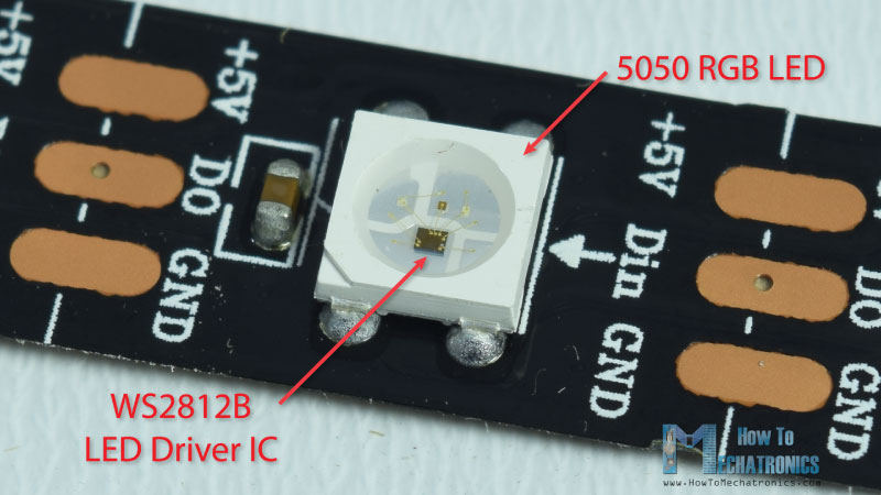
Depending on the intensity of the three individual Red, Green, and Blue LEDs we can simulate any color we want.
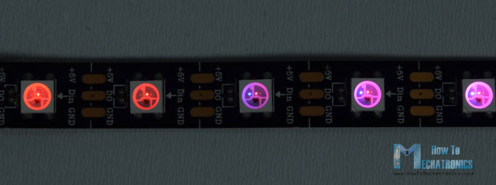
What’s great about these LEDs is that we can control even the entire LED strip with just a single pin from our Arduino board. Each LED has three connectors at each end, two for the powering and one for the data. The arrow indicates the data flow direction. The data output pad of the previous LED is connected to the Data Input pad of the next LED. We can cut the strip to any size we want, as well as distance the LEDs using some wires.
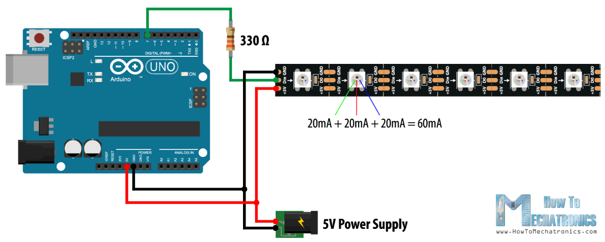
As for the powering they work on 5V and each Red, Green and Blue LED draws around 20mA, or that’s total of 60mA for each LED at full brightness. Note that when the Arduino is powered via the USB, the 5V pin can handle only around 400 mA, and when powered using the barrel power connector, the 5V pin can handle around 900 mA.
If you are using more LEDs and the amount of current that they would draw exceeds the limits mentions above, you must use a separate 5V power supply. In such a case you also need to connect the two Ground lines two each other. Additionally it is recommended to use a resistor of around 330 Ohms between the Arduino and the LED strip data pin in order to reduce the noise on that line, as well as a capacitor of around 100uF across the 5V and Ground to smooth out the power supply.
Arduino and WS2812B LEDs Examples
Example 1
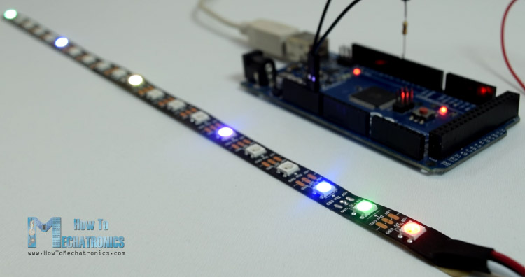
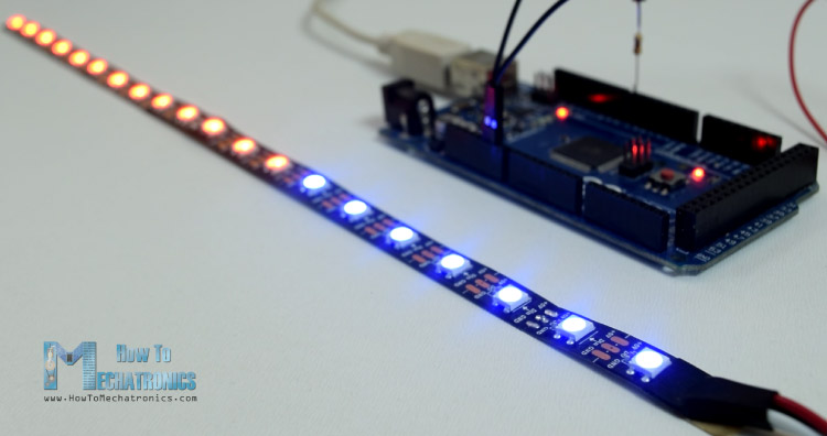
Now as an example I will use 20 LEDs long strip, connected to the Arduino through a 330 Ohms resistor and powered with a separate 5V power supply, just as explained above. For programming the Arduino, we will use the FastLED library. This is an excellent and well documented library which enables easy control of the WS2812B LEDs.
You can get the components needed for this example from the links below:
- WS2812B LED Strip ………………….. Amazon / Banggood / AliExpress
- Arduino Board …………………………… Amazon / Banggood / AliExpress
- 5V 6A DC Power Supply ……………… Amazon / Banggood / AliExpress
Disclosure: These are affiliate links. As an Amazon Associate I earn from qualifying purchases.
Here’s the Arduino source code for first example:
#include <FastLED.h>

#define LED_PIN     7
#define NUM_LEDS    20

CRGB leds[NUM_LEDS];

void setup() {

  FastLED.addLeds<WS2812, LED_PIN, GRB>(leds, NUM_LEDS);

}

void loop() {

  leds[0] = CRGB(255, 0, 0);
  FastLED.show();
  delay(500);
  leds[1] = CRGB(0, 255, 0);
  FastLED.show();
  delay(500);
  leds[2] = CRGB(0, 0, 255);
  FastLED.show();
  delay(500);
  leds[5] = CRGB(150, 0, 255);
  FastLED.show();
  delay(500);
  leds[9] = CRGB(255, 200, 20);
  FastLED.show();
  delay(500);
  leds[14] = CRGB(85, 60, 180);
  FastLED.show();
  delay(500);
  leds[19] = CRGB(50, 255, 20);
  FastLED.show();
  delay(500);
}Code language: PHP (php)
Desctiption: So first we need to include the FastLED library, define the pin to which the LED strip data is connected, define the number of LEDs, as well as define an array of type CRGB. This type contains the LEDs, with three one-byte data members for each of the three Red, Green and Blue color channel.
In the setup section we just need to initialize the FastLED with the parameters with defined above. Now it the main loop we can control our LEDs anyhow we want. Using the CRGB function we can set any LED to any color using three parameters of Red, Green and Blue color. In order to make the change happen on the LEDs we need to call the function FastLED.show().
Example 2
Using some “for” loops we can easily make some animations.
Here’s the Arduino source code for second example:
#include <FastLED.h>

#define LED_PIN     7
#define NUM_LEDS    20

CRGB leds[NUM_LEDS];

void setup() {

  FastLED.addLeds<WS2812, LED_PIN, GRB>(leds, NUM_LEDS);

}

void loop() {

  for (int i = 0; i <= 19; i++) {
    leds[i] = CRGB ( 0, 0, 255);
    FastLED.show();
    delay(40);
  }
  for (int i = 19; i >= 0; i--) {
    leds[i] = CRGB ( 255, 0, 0);
    FastLED.show();
    delay(40);
  }
}Code language: HTML, XML (xml)
Here the first “for” loop lights up all 20 LEDs in blue, from the first to the last LED with 40 milliseconds delay. The next “for” loop lights up again all 20 LEDs, but this time in red color and in reverse order, from the last to the first LED.
The FastLED library features many other functions which can be used for making really interesting animations and light shows, so it’s only up to your imagination to make your next LED project shine.
Interactive LED Coffee Table using the WS2812B LEDs
Now let’s take a look at the DIY interactive LED coffee table project that I mentioned at the beginning. So this was a collaboration project between with me and Marija from Creativity Hero.

You can check her website article where she explains the entire process making the table, starting from cutting and assembling the wooden construction, to soldering and connecting all electronics parts together. Here I will explain how the electronics part work, how to build the custom Android application and program the Arduino board.
Here’s the complete circuit schematic of this project.
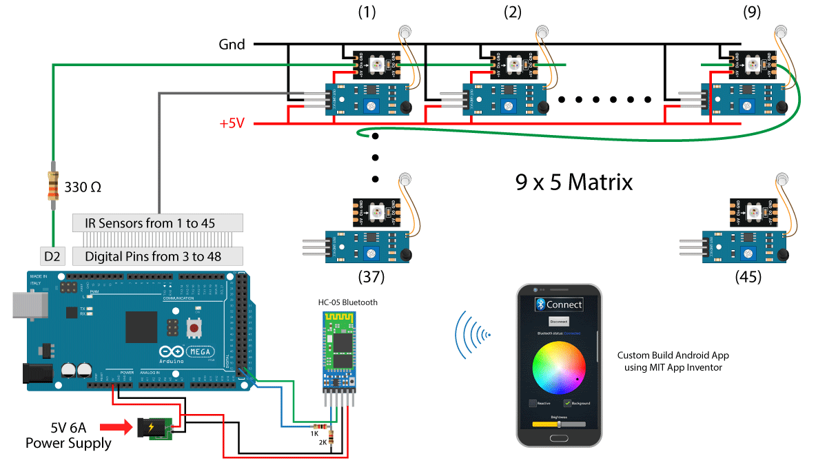
So the table consist of 45 addressable LEDs, 45 infrared proximity sensors and a HC-05 Bluetooth module, all of them connected to an Arduino Mega board. The circuit is powered with a 5V 6A power supply.
You can get the components needed for this example from the links below:
- WS2812B LED Strip ………………….. Amazon / Banggood / AliExpress
- IR Proximity Sensor …………………… Amazon / Banggood / AliExpress
- HC-05 Bluetooth Module …….…… Amazon / Banggood / AliExpress
- Arduino Board …………………………… Amazon / Banggood / AliExpress
- 5V 6A DC Power Supply ……………… Amazon / Banggood / AliExpress
Disclosure: These are affiliate links. As an Amazon Associate I earn from qualifying purchases.
Related: How to use a RGB LED with Arduino | Tutorial
Source Codes
Here’s the Arduino code for this project and if we exclude the Bluetooth color control feature, we can notice that the code is actually very simple.
#include "FastLED.h"

#define NUM_LEDS 45
#define LED_PIN 2
#define COLOR_ORDER GRB

CRGB leds[NUM_LEDS];

void setup() {
  FastLED.addLeds<WS2812, LED_PIN, COLOR_ORDER>(leds, NUM_LEDS);
  FastLED.setBrightness(brightness);
  // Set the 45 proximity sensors pins as inputs, from digital pin 3 to pin 48
  for (int pinNo = 0 + 3; pinNo <= 45 + 3; pinNo++) {
    pinMode(pinNo, INPUT);
  }
}

void loop() {
  for (int pinNo = 0; pinNo <= NUM_LEDS-1; pinNo++) {
    leds[pinNo] = CRGB( 0, 255, 0);    // Set all 45 LEDs to green color
    // If an object is detected on top of the particular sensor, turn on the particular led
    if ( digitalRead(pinNo + 3) == LOW ) {
      leds[pinNo] = CRGB( 0, 0, 255); // Set the reactive LED to bluee
    }
  }
  FastLED.show(); // Update the LEDs
  delay(20);
}Code language: PHP (php)
Desctiopion: First we need to define the basic parameters as explained earlier and set the 45 proximity sensors pins as inputs.
In the main loop using a single “for” loop we set all LEDs to a particular color, and also check whether the proximity sensor has detect an object. If that’s true, or a LOW logic state in this case, the particular reactive color will be set to the particular LED. At the end using the FastLED.show() function we update the LEDs colors.
For including the Bluetooth color control feature we need to add some more lines of code as well as make the Android app. I already have separate tutorials on how to use the HC-05 Bluetooth module with Arduino and how to make your own Android application using the MIT App Inventor online application, so you can always check them for more details.
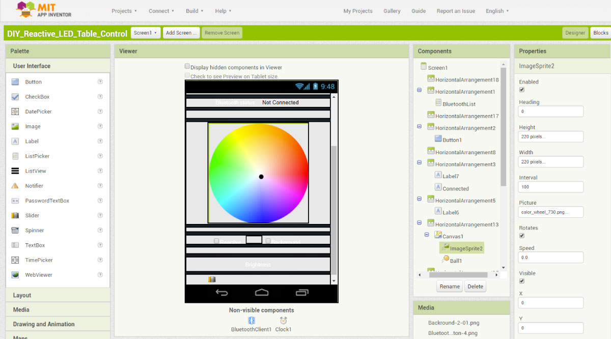
Here’s how the Android app works. It consist of a color palette image from where we can pick up colors, two check buttons from where we can select whether the chosen color will be be applied to the reactive or the background LEDs and a slider for adjusting the brightness.
If we take a look at blocks of the app, we can see what happens when we touch the canvas where the color palette image is placed. Using the .GetPixelColor blocks we get the Red, Green and Blue values for the picked up color and using the Bluetooth SendText block we send this information to the Arduino in a form of text.
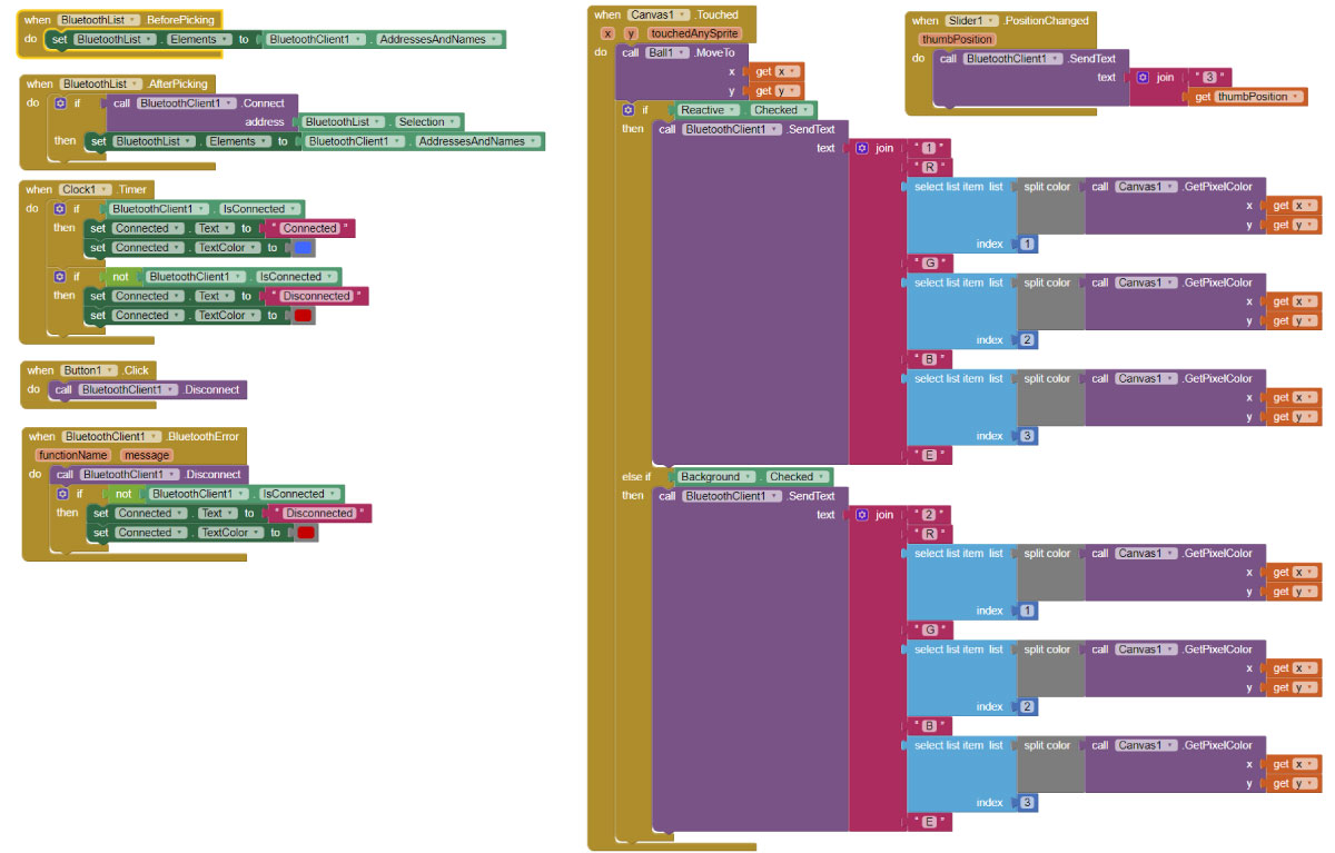
Depending on the selected check box, we send a different first character or marker which helps when receiving the text at the Arduino. The same happens when we change the position of the slider, a value from 10 to 100 is sent to the Arduino in a form of text, with the marker “3” in front.
You can download the Android app below, as well as the MIT App Inventor project file:
Here’s the Arduino code:
#include <SoftwareSerial.h>

#include "FastLED.h"

#define NUM_LEDS 45
#define LED_PIN 2
#define COLOR_ORDER GRB

CRGB leds[NUM_LEDS];

SoftwareSerial Bluetooth(53, 52); // Arduino(RX, TX) - Bluetooth (TX, RX)

// Initial background color
int backR = 100;
int backG = 50;
int backB = 10;

// Initial reactive color
int reactiveR = 10;
int reactiveG = 50;
int reactiveB = 100;

int brightness = 50; // Initial brightness

String dataIn = "";

void setup() {
  FastLED.addLeds<WS2812, LED_PIN, COLOR_ORDER>(leds, NUM_LEDS);
  FastLED.setBrightness(brightness);
  Serial.begin(38400);
  Bluetooth.begin(38400); // Default baud rate of the Bluetooth module

  for (int pinNo = 0 + 3; pinNo <= 45 + 3; pinNo++) {
    pinMode(pinNo, INPUT);
  }
}

void loop() {
  if (Bluetooth.available() > 0) {
    dataIn = Bluetooth.readString();
    delay(20);
    if (dataIn.startsWith("1")) {
      delay(10);
      String stringR = dataIn.substring(dataIn.indexOf("R") + 1, dataIn.indexOf("G"));
      reactiveR = stringR.toInt();
      String stringG = dataIn.substring(dataIn.indexOf("G") + 1, dataIn.indexOf("B"));
      reactiveG = stringG.toInt();
      String stringB = dataIn.substring(dataIn.indexOf("B") + 1, dataIn.indexOf("E"));
      reactiveB = stringB.toInt();
    }
    else if (dataIn.startsWith("2")) {
      String stringR = dataIn.substring(dataIn.indexOf("R") + 1, dataIn.indexOf("G"));
      backR = stringR.toInt();
      String stringG = dataIn.substring(dataIn.indexOf("G") + 1, dataIn.indexOf("B"));
      backG = stringG.toInt();
      String stringB = dataIn.substring(dataIn.indexOf("B") + 1, dataIn.indexOf("E"));
      backB = stringB.toInt();
    }
    else if (dataIn.startsWith("3")) {
      String stringBrightness = dataIn.substring(dataIn.indexOf("3") + 1, dataIn.length());
      brightness = stringBrightness.toInt();
      FastLED.setBrightness(brightness);
    }
  }

  for (int pinNo = 0; pinNo <= NUM_LEDS-1; pinNo++) {
    leds[pinNo] = CRGB( backR, backG, backB);
    if ( digitalRead(pinNo + 3) == LOW ) {
      leds[pinNo] = CRGB( reactiveR, reactiveG, reactiveB);
    }
  }
  FastLED.show();
  delay(20);
}Code language: PHP (php)
Description: First we need to define the serial communication between the Arduino and the HC-05 Bluetooth module, or the pins to which the module is connected. In the setup section we need to set the baud rate at which this module works. Then in the main loop using the Bluetooth.available() function we check whether there is an incoming data from the Smartphone. If that’s true, using the Bluetooth.readString() function we receive the data as string. Then using the .startsWith() function we check the first character or the marker and in that way know whether we want to change the reactive color, the background or the brightness.
Using the .substring() function we extract the Red, Green and Blue values from the received text and convert them into integers. These values are then used in the “for” loop below which sets the color and lights up the LEDs as explained earlier. In the same way we adjust the brightness of the LEDs.
So that’s all for this tutorial. Feel free to ask any question in the comments section below.
Thank you 🙏 so nicely explained, cleared many doubts I had about WS 2812.
Thank you!
I’m glad it was helpful!
Hi
Very nice project!
I saw a lot of infinity projects and will ask you, how to modify the code, so that it is possible to address more then 1 LED per sensor.
Regards
Guido
Sure you can control more then 1 LED per sensor. It’s all about adjusting the code.
Hey,
great explanation! But i have got one question:
Is there a problem connecting a 5V 4A power source directly to the Arduino boards 5V pin? I want to power both the LED strip and the board with one power source, but i am not sure if it will fry my board…?
Hey, thanks! Yes, you can power the Arduino with the 5V 4A power supply through the Arduino 5V pin.
**Question**
Hi there, great tutorial I found it really interesting! I’m completely new to Arduino’s and doing some projects like this. But have an idea i’d like to try involving the same LED strips.
My question is around the Arduino itself and how many different modules there are, but for a similar project where I want to control an 45 LED’s do I need an Arduino MEGA? or can use a cheaper module (like the UNO) if so which one?
Hey, thanks! Well if you want to control 45 LEDs of this type, WS2812B, then you can use even the smallest Arduino, NANO or PRO MINI. For controlling these LEDs you just need a single digital pin from the Arduino, and a dedicated power source of course.
Hi
I love your program and idea, but the RGBW strip you are linking to on Banggood is not supported by FastLed. It only support RGB strips. The Adafruit Neopixel library support both RGBW and RGB strips, but your program must be rewritten if that should be used.
Took some time for me to figure it out. I thought the RGBW strip had an error, but with the correct library it works fine.
Regards, SveinM
Hey, thanks for pointing that out. I’ve updated the link now to the correct RGB strips.
Hello,
first, great Projekt !
Is it possible that you can explain me how the subString function works?
Especially i didnt understand the Part with the +1.
What does the +1 means?
Kind reguards
Hey thanks! The subString function extracts just the part of the string that we want. Here’s the meaning of my example with the “+1” part you mentioned:
The values we are getting from the phone are, for example, R255G220B123. So with the indexOf() function we first locate the R character, and that’s index 1 in this case, but with want our string to start from the next index, or +1 and that’s index 2. And on the other hand we want our string to end at the G character (it won’t include the G char). So the extracted string will be just 255 which can be then converted into integer value.
Hello Dejan , just one question regarding capacitor type/size, i will need to use a power supply of 5V20A on WS2812b 5m 60leds/m :
I quote you ”, as well as a capacitor of around 100uF across the 5V and Ground to smooth out the power supply” – can you please be more specific where exactly should be placed the capacitor and wich type according my power supply and led strip ?
I guess is a stupid question but i have no idea , just started to learn and hopefully finish what i have started.
Thank you in advance .
Hello there, this capacitor is called “bypass” or “decoupling” capacitor. It is used in case there is a sudden drop in voltage then the circuit uses the stored charge from the capacitor to maintain the voltage stable.
Actually it’s not that critical for these LEDs but it’s ok to use one. In case of 5m it’s recommended to use something around 100-500uF with voltage of courese above 5V, so 16V, 25V, 35V or so. The capacitor is place as close as possible to the LED strip, and its positive pin goes to the positive pin of the strip pin and the negative to the negative strip or GND.
In this for loop (lines 66-69):
for (int pinNo = 0; pinNo <= 45; pinNo++) {
leds[pinNo] = CRGB( backR, backG, backB);
if ( digitalRead(pinNo + 3) == LOW ) {
leds[pinNo] = CRGB( reactiveR, reactiveG, reactiveB);
When pinNo is 45 it's going to try to write pixel data to leds[45] which doesn't exist since NUM_LEDS is 45 (ie. you only have leds[0] to leds[44]). Writing data to pixels that don't exist often causes bad things to happen in memory, random pixel flashes, or even code execution lockups.
To make the code less likely to break when copied and the value of NUM_LEDS is changed you might consider updating the for loop line to be this:
for (int pinNo = 0; pinNo <= NUM_LEDS-1; pinNo++) {
Thanks for the input, that’s a good one. I’ve updated the post as so. Actually it can be even stated only “pinNo < NUM_LEDS;" without "-1" if the sign is just "<" instead of "<=".
Line 33 could also be updated to use the variable NUM_LEDS.
Hi Dejan,
Thank you for posting this (:
I’m using your project example to build a different personal project.
Im stuck ): and perhaps you can help me
Im trying to light ws2812B LEDS strip with the app and I used your Arduino code.
Since Im not using any IR sensors i dropped out of the code the lines:
for (int pinNo = 0 + 1; pinNo <= 2 + 1; pinNo++) {
pinMode(pinNo, INPUT);
and
for (int pinNo = 0; pinNo <= 2; pinNo++) {
leds[pinNo] = CRGB( backR, backG, backB);
if ( digitalRead(pinNo + 1) == LOW ) {
leds[pinNo] = CRGB( reactiveR, reactiveG, reactiveB);
But I can't get it to change the colors.
What I would love to get is:
Controlling WS2812B led strip with the app without any input. I would greatly appreciate if you can help me clear up what I need to change in Arduino code and MIT App since I got lost (;
Thanks
Hey, well in such a case with the same app you could only change the color to all LEDs at the same time to same color.
So you could still use the “reactiveR/G/B” variables for setting the color, so right instead of the code you mention in the comment, you could use a simple a for loop for activating all LEDs with those “reactiveR/G/B” variables values. Something like:
for (int pinNo = 0; pinNo <= 45; pinNo++) { leds[pinNo] = CRGB( reactiveR, reactiveG, reactiveB); } This should work, although I cannot test it at this moment.
on my led strip i have 60 led`s, how do i use all of them?
In the same way as I explained in the tutorial above, just change the number of LED you are using in the Arduino code. Also make sure you have enough power, you need at around 4A 5V power supply (60LEDs x 60mA = 3600mA = 3.6A).
Hi,
Could you please explain how to get the FAST LEd library installed and working? I cannot get this to work so I cannot get the programs working.
Many Thanks
Rob
Just make sure you include the FAST LED library into your Arduino libraries directory.
hello dejan sir can u make google assistance echo device like amazon echo who can control our home electrical things , music, and reply like amazon echo i will be thankfull to u… thanks sir
thank you soooo much sir u guys r awesome and can u make music player which can control by us (Example : ok jarvis play track i like u by eminem) through arduino…. i will be very thankfull if u can make this type of project….thanks again sir
Sorry for the late response. Well the problem is that we didn’t have enough gray wire for all IR sensors and for some of them we used green, that’s probably what confuse you.
Anyway, the IR outputs from 0 to 45 go to digital pins of Arduino 3 to 48. As for the LEDs we only have one pin in use, that’s pin number 2.
waiting for ur reply…..
very nice project but can u tell me which pins are for ir sensor and which for digital i am confused with picture (grey pins connection and green pins connection) so can u tell me proper connection of grey and green wires….thanks
In the circuit schematic the grey wires go to each IR sensor, and green wire goes from Arduino to the first LED, and then from each previous to next LED.
thanks sir but can u tell me in arduino mega which pins are for IR sensor and which r for digital i am confused…
Example: In arduino mega board which pins we connect in ir connection and which for digital (green wire) connection can u plzz tell me becoz in diagram i am confused in these ir and digital connection…..thanks
becoz in video she connect many grey and green wires to arduino mega so can u plzz tell me which pins for grey connection and which for green… thanks