In this tutorial I will show you how I built a replica of the Mars Perseverance Rover. Of course, inspired by the real rover which is currently exploring Mars, I designed this rover in a way that everyone who love this technology, students, makers, mechatronics or robotics enthusiast, and so on, can easily follow the instructions in this video and build their own Mars Rover.
You can watch the following video or read the written tutorial below.
Overview
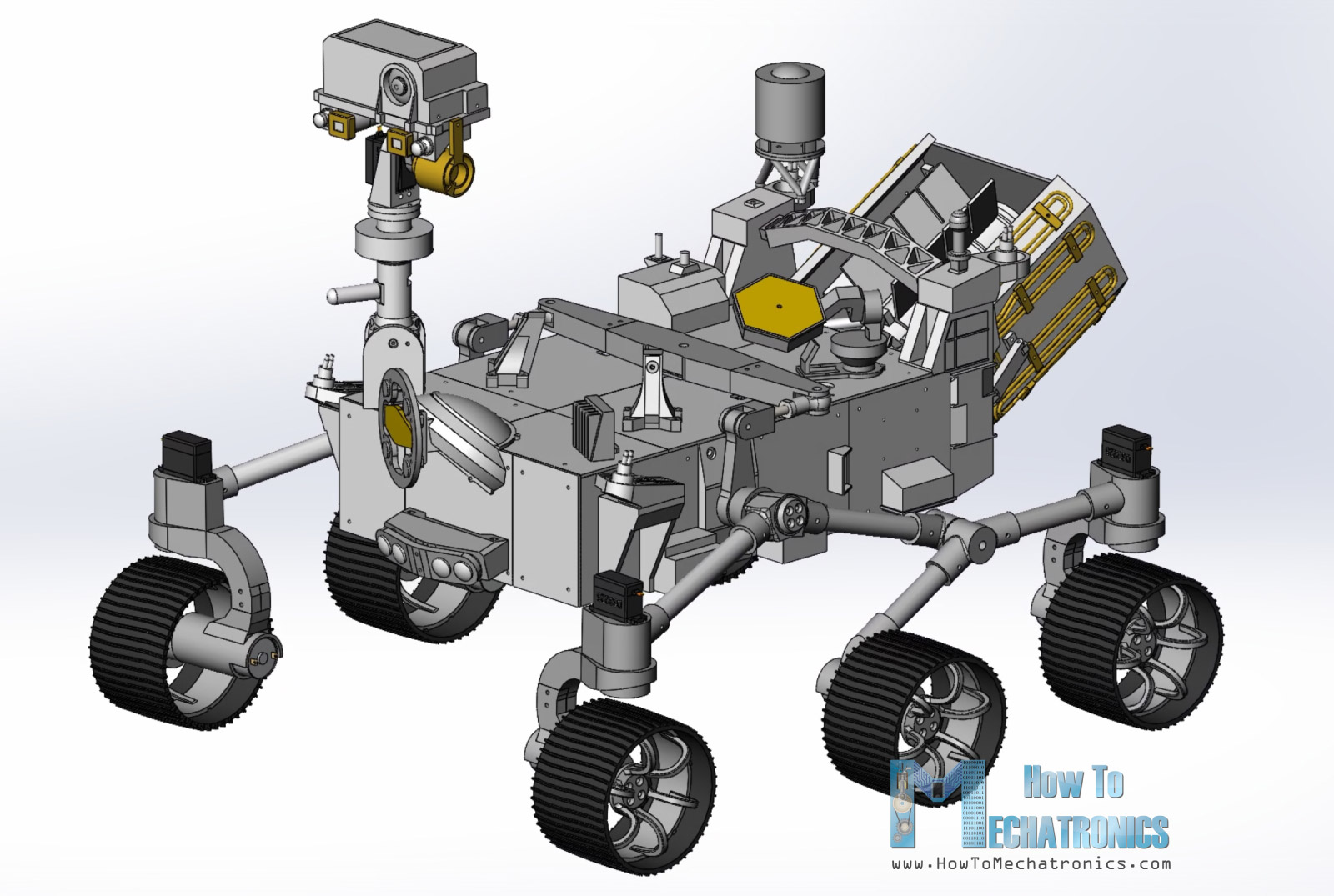
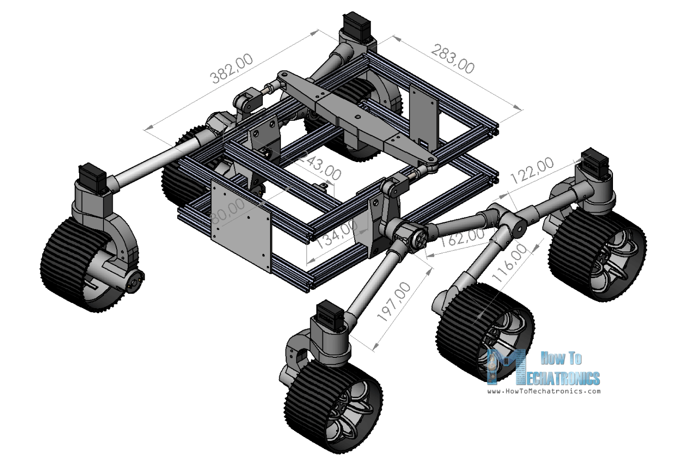
Let’s take a look at the main features of this rover. It employs a rocker-bogie suspension which allows the rover to run smoothly on uneven terrain and climb obstacles, such as rocks, that are up to twice the wheel’s diameter in size while keeping all six wheels in contact with the ground all time. Each wheel has independent DC motor which drives the rover forward or backward.
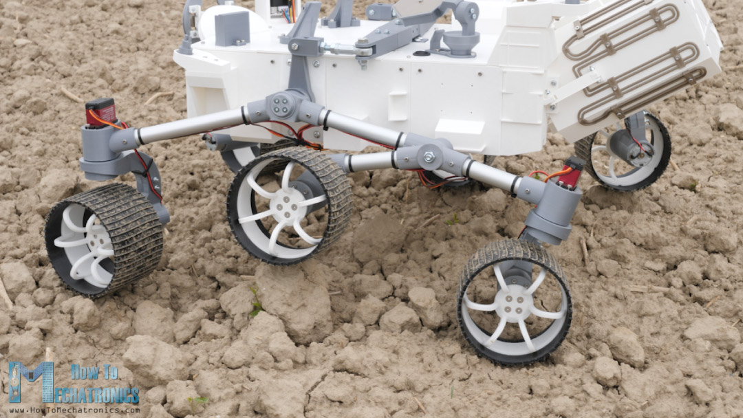
The four corner wheels have individual steering servo motors. In order to efficiently steer the rover and avoid tire slipping when driving around a curve, we are implementing the Ackermann steering geometry. With this geometry we can calculate the speed and angle of each wheel depending on the turning radius.
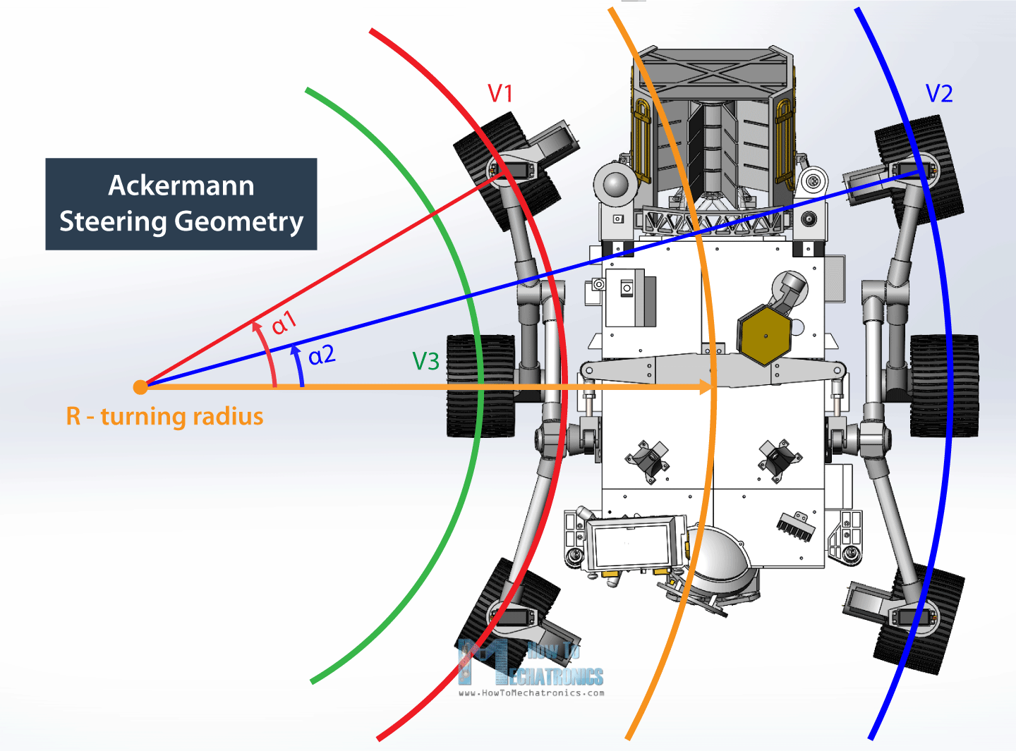
This means that, when turning, the inner steering wheels will have a greater angle compared to the outer wheels. At the same time, the inner wheels will have slower speeds compared to the outer wheels.
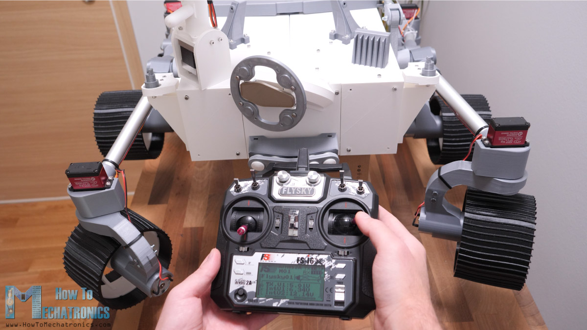
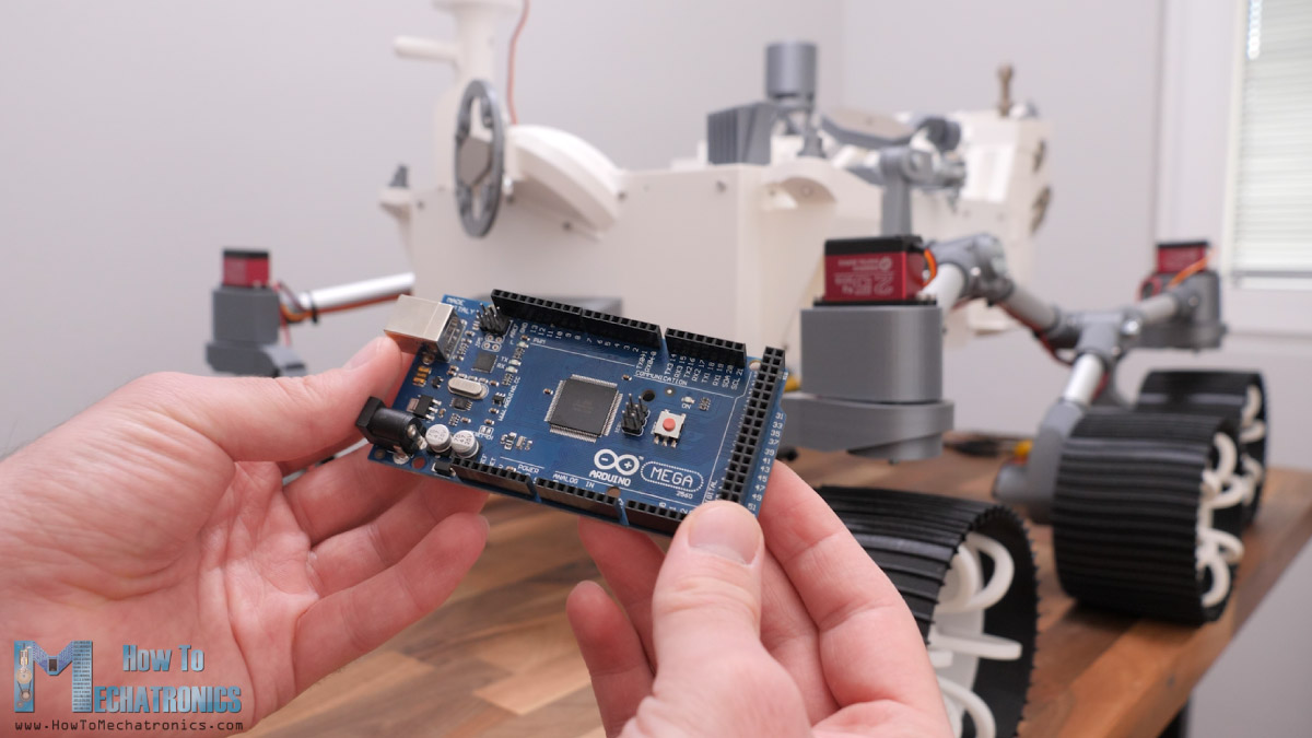
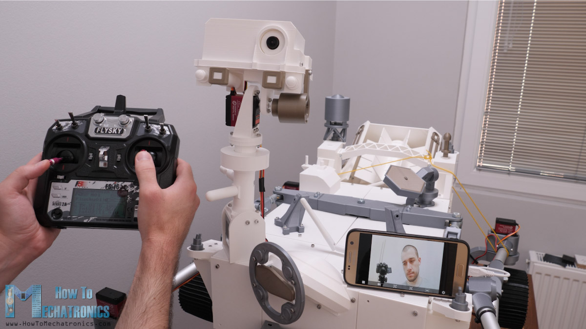
For controlling the rover, I’m using a cheap commercial RC Transmitter which sends commands to the rover. At the rover I have suitable RC receiver which receives the commands and sends them to an Arduino board. Yes, the brain of this Mars rover is actually an Arduino MEGA board and for easily connecting everything together I made a custom PCB which can be simply attached on top of the Arduino MEGA board.
The rover also features an FPV camera located in the cameras unit. It is controlled using a stepper and a servo motor and I’m receiving the real-time video on a smartphone.
I would like to note here that many of the parts are actually not functional, or they are present just to match the appearance of the real rover. Also, the robotic arm is missing, but I plan to make the arm and add more functions to this rover in future videos.

Nevertheless, now let me walk you through the process of building it, starting from designing the rover, connecting the electronics components and programing the Arduino board.
DIY Mars Rover 3D Model
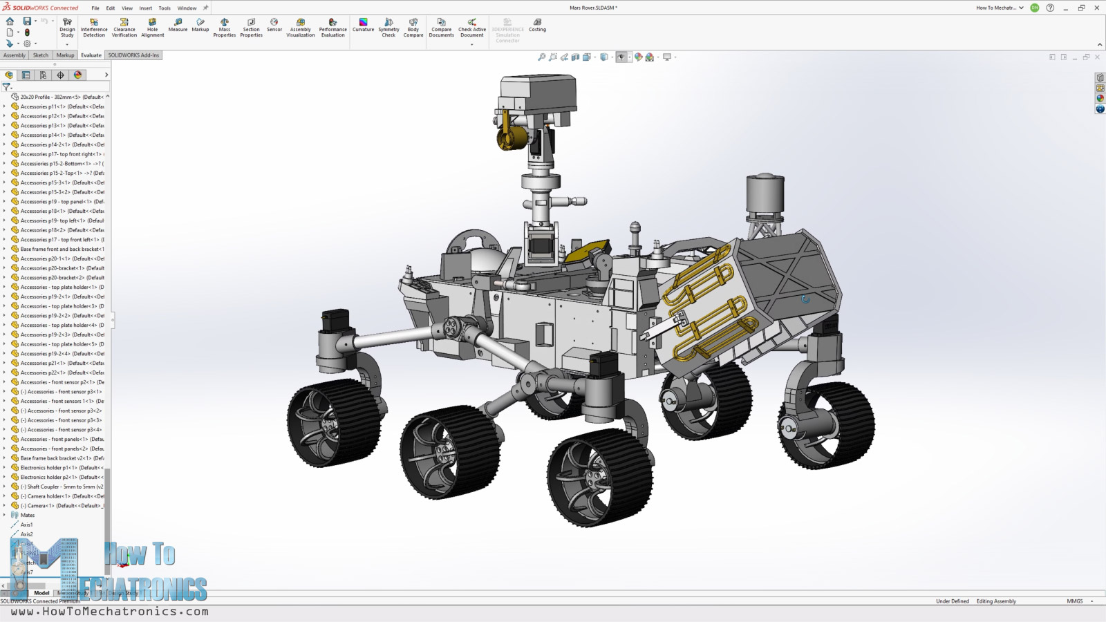
I designed this Mars rover using 3D EXPERIENCE Solidworks which are actually the sponsor of this video.
3DEXPERIECE Solidworks is a version of Solidworks with cloud capabilities which we get through the 3DEXPERIECE platform. Here everything works through the cloud, so you or anyone from your team can have accesses to the data or the models at any time, from anywhere in the world. The 3DEXPERIECE platform also includes many useful productivity and data management apps.
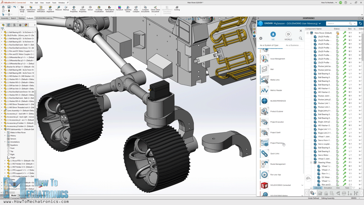
For example, the Project Planning app is a great way to organize your tasks, set deadlines and keep track of your progress. With the 3D Markup app, you can view, explore and take notes of the models from any device, like a notebook, tablet or even a smartphone.
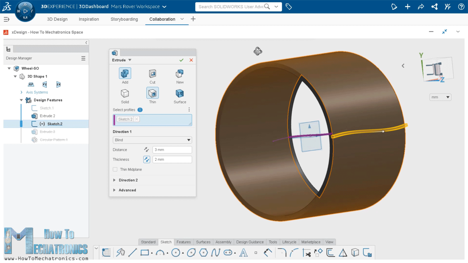
There is also a separate, cloud-based 3D modeler called SOLIDWORKS xDesign, that runs inside your browser. It can be used in conjunction with Solidworks or on its own and it’s great for modeling, anywhere, anytime and on any device.
Nevertheless, probably the most exciting news for many of you guys here is that starting from second half of this year, there will be a maker version of 3DEXPERIECE Solidworks which you can get for only $99 per year. Big thanks to Solidworks for sponsoring educational content like this.
If you would like to know whether SOLIDWORKS and the 3DEXPERIENCE platform can work for you, check the following links below.
Try 3DEXPERIENCE for free with my special link: www.solidworks.com/HTMTryNow
Learn more about 3DEXPERIENCE SOLIDWORKS: www.solidworks.com/HTMLearnMore
3DEXPERIENCE SOLIDWORKS for Makers: www.solidworks.com/htm
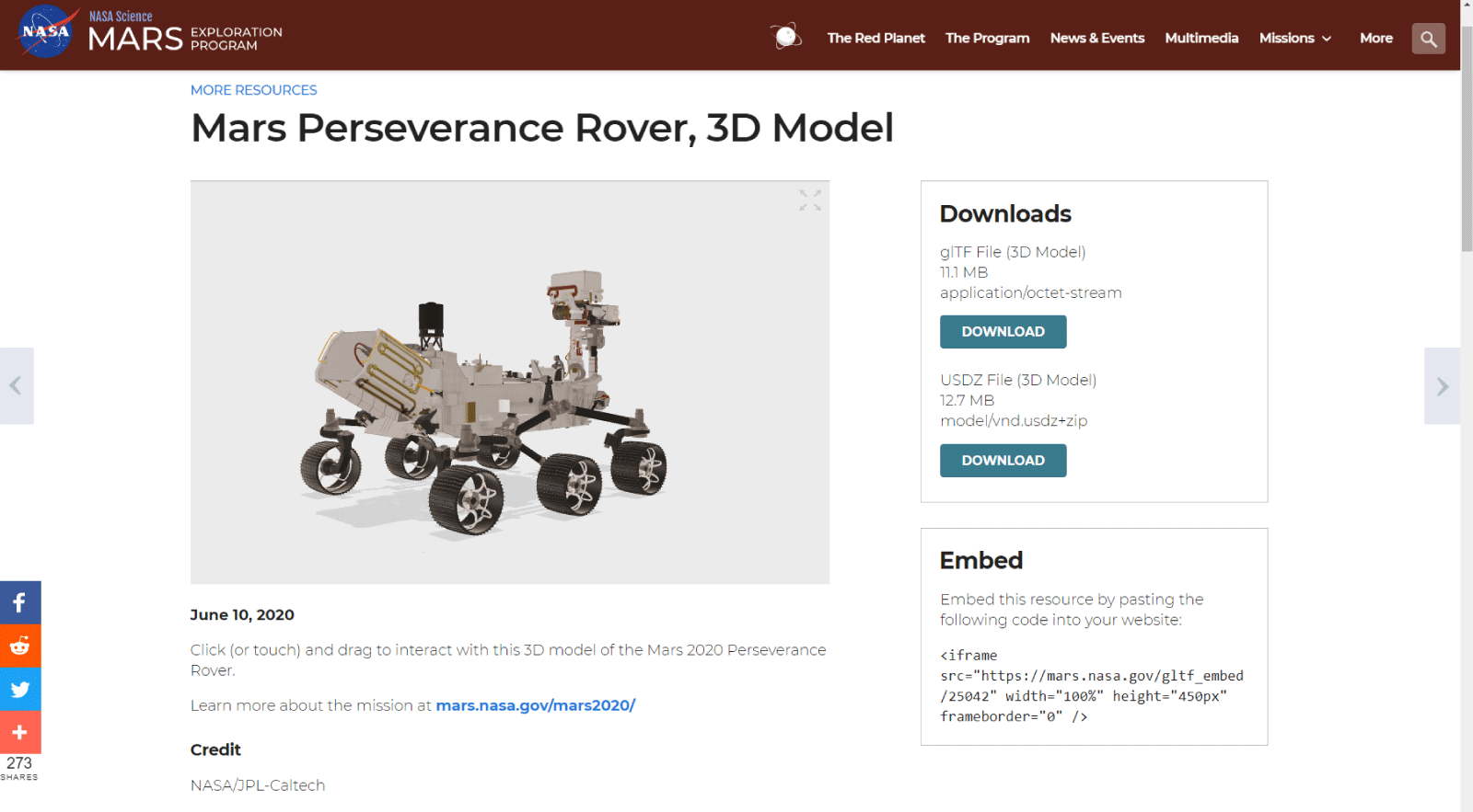
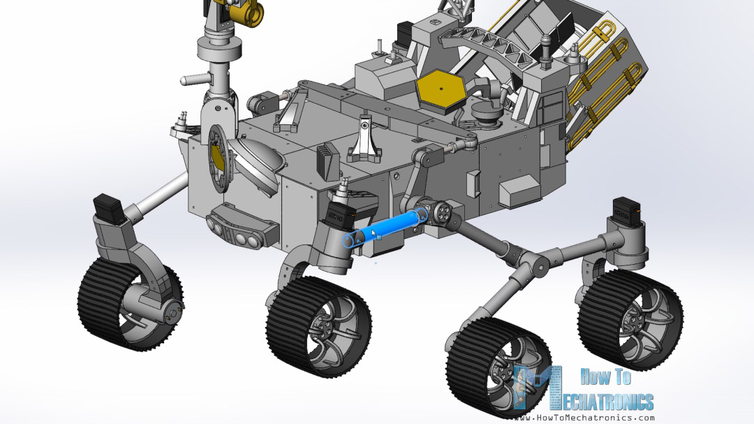
Ok, so let’s get back to the model and explain how I designed the rover. My goal was to make this rover look as close as possible to the real Mars Perseverance Rover. On the official NASA website there is a 3D model of the Mars Perseverance Rover, so I downloaded and opened it in Blender.
I took 3 pictures of the front, top, and side view of the rover and imported them in Solidworks. I wanted the size of the wheels to be 130mm in diameter, so I scaled the pictures according to this dimension.
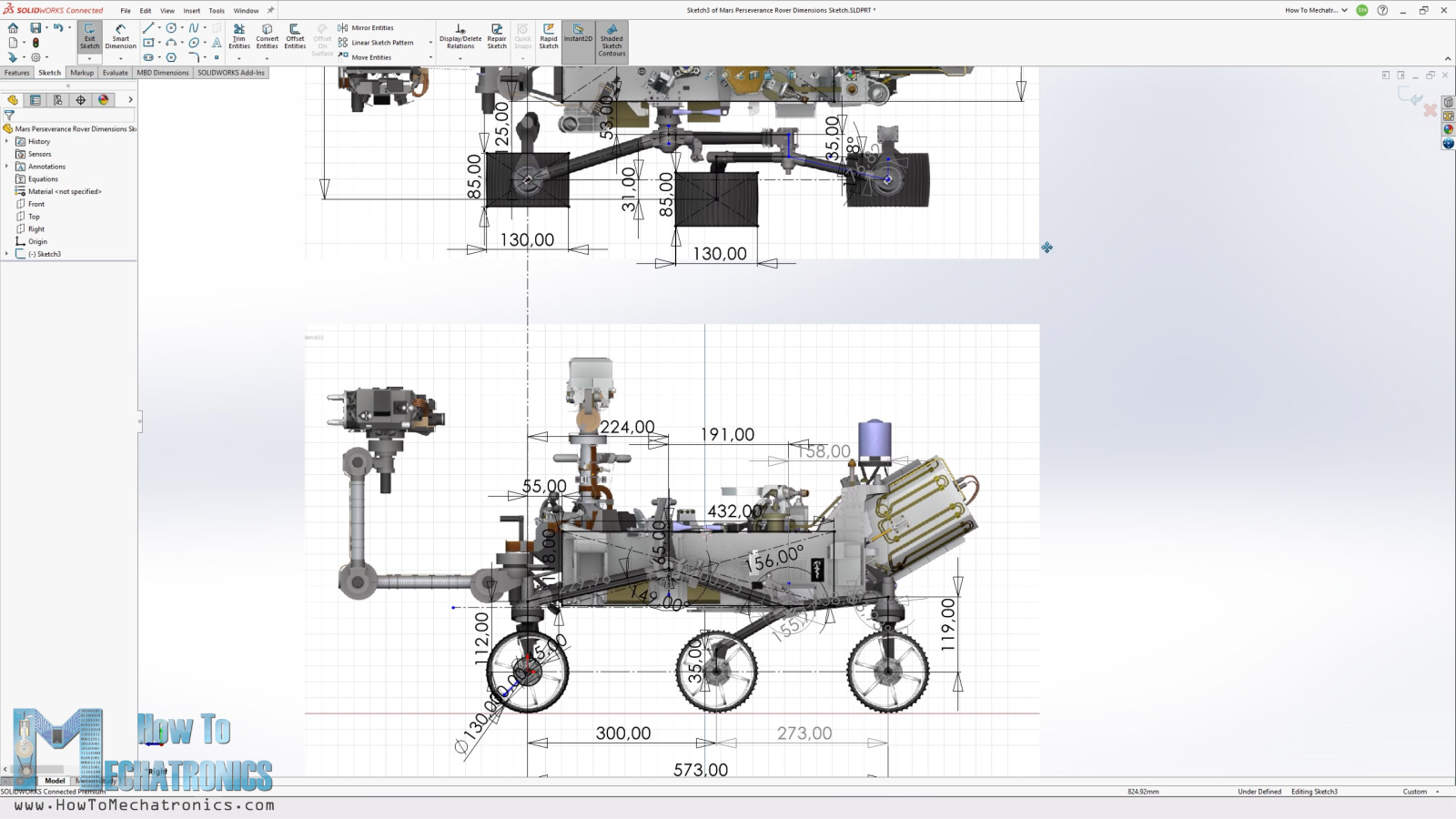
Then from here I took all key dimensions, like the width, length, height, distance between wheels, dimensions for the rocker-bogie suspension and so on.
Now according to these dimensions and the DC motors and servos that I planned to use, I designed the rover parts in a way that they can be easily 3D printed and assembled while trying to keep the appearance as close as possible to the original.
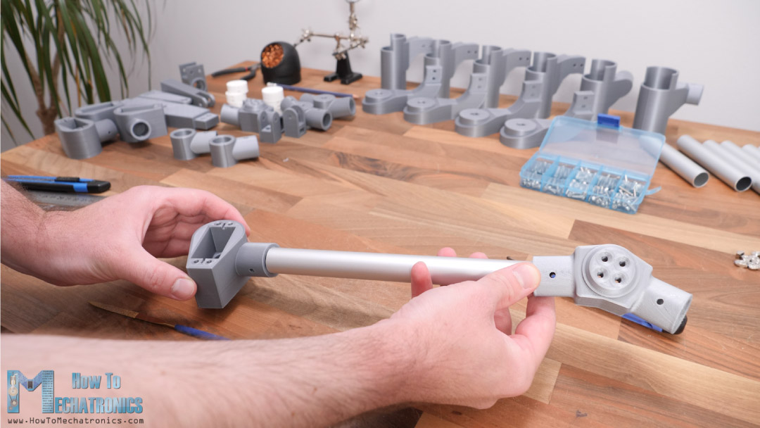
For the rocker-bogie suspension I’m using 20mm round aluminum profiles, whereas for the base frame I’m using 20mm T-slot aluminum profiles.
3D Model and STL Download Files
You can get this 3D model, as well as the STL files for 3D Printing from Cults3D.

3D Printing the Mars Rover Replica Parts
For 3D printing the parts I used my old Creality CR-10 as well as the new CR-10 V3 3D printer. If you want print the wheels with flexible material you will definitely need a printer with direct extruder just like the CR-10 V3 is.
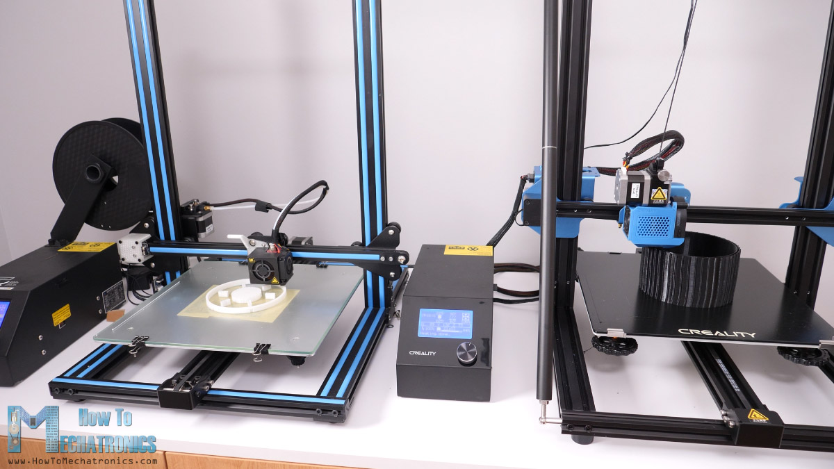
Both of these 3D printers provide great printing quality while being relatively affordable. If you are interested, here are links to them so you can check them out:
- Creality CR-10…… Amazon / Banggood
- Creality CR-10 V3…… Amazon / Banggood / AliExpress
Disclosure: These are affiliate links. As an Amazon Associate I earn from qualifying purchases.
See also: Best Budget Oscilloscopes for Beginners and Makers – 2021 Update
When 3D printing the parts, it’s important to use the Horizontal Expansion feature in you slicing software. I used a value of –0.1mm. This feature compensates the expansion of the filament when printing.
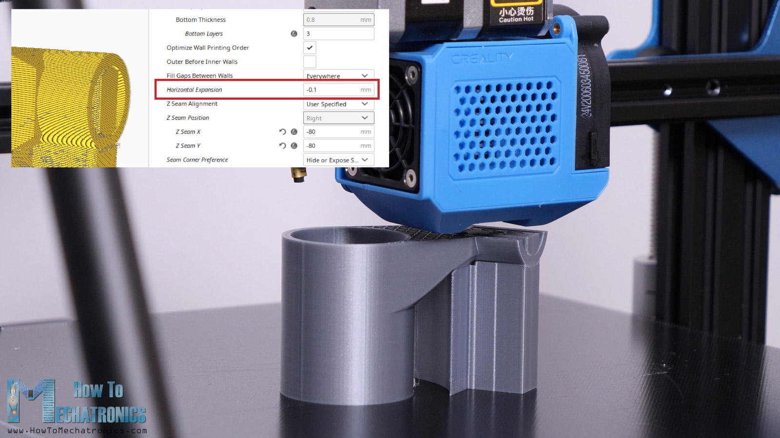
If not used, for example, if the part has a hole with diameter of 20mm, the hole of the actual 3D printed part will be around 19.8mm and we won’t be able to assemble it.
Nevertheless, here are all of the 3D printed parts.
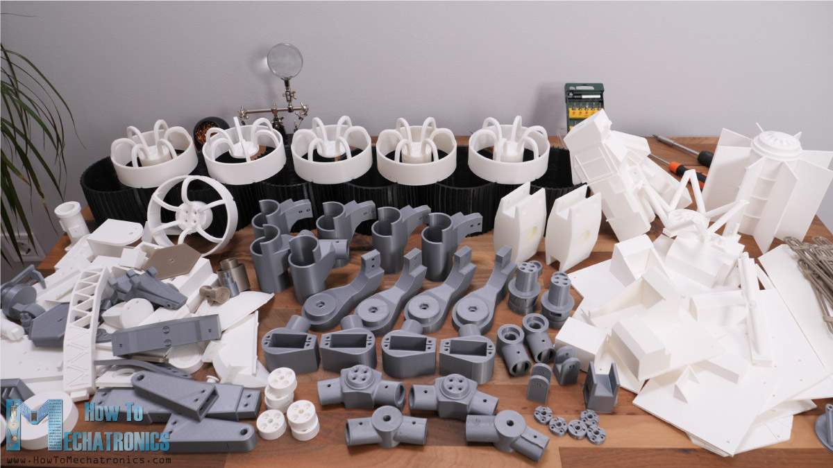
To be honest it’s a bit crazy how much printing there is, but it’s the only way to get the unique appearance of the rover. Though, you can cut the printing time in half if you choose to print only the functional parts of this rover.
Parts list for the DIY Mars Rover
Here’s a list of components needed for assembling this DIY Mars Rover. The list for the electronics components can be found below in the circuit diagram section of the article.
- T-slot aluminum profiles 20x20mm ………..Amazon / Banggood / AliExpress
- T-slot profile corner brackets ……………..… Amazon / Banggood / AliExpress
- Aluminum Round Tube 20mm ………………. Amazon / AliExpress
- Rod End Joint 8mm ………………………………….. Amazon / Banggood / AliExpress
- 8 x Bearing 608RS – 8x22x7mm ……..…… Amazon / Banggood / AliExpress
- 8 x Bearing 626RS – 6x19x6mm ………….… Amazon / Banggood / AliExpress
- 5 x Bearing 625RS – 5x16x5mm …………… Amazon / Banggood / AliExpress
- M3 Bolts various lengths ………………………… Amazon / Banggood / AliExpress
- 4 x Servo horns …………………………………………. Amazon / Banggood / AliExpress
Disclosure: These are affiliate links. As an Amazon Associate I earn from qualifying purchases.
We also need various lengths of M4, M5 and M6 bolts. You can check the completed list of bolts and nuts needed below.
You can also get the bolts and the nuts from your local hardware store.
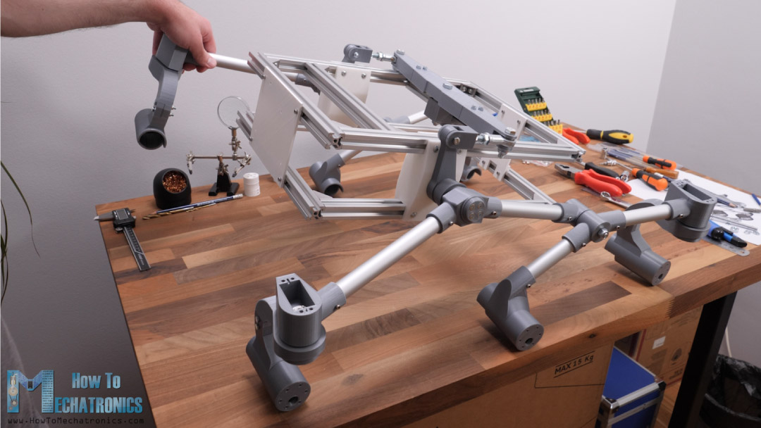
Assembling the Rover
All right, now we can start assembling the rover. First, we need to prepare the aluminum profiles. I used a metal hand saw to cut them to size.
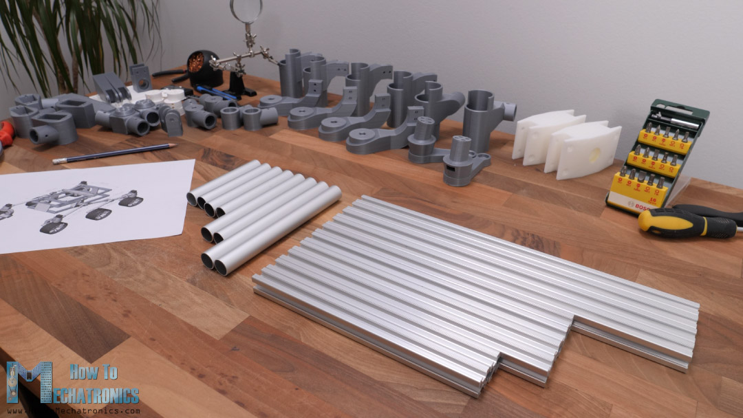
We need 10 T-slot profiles for the base and 8 round profiles for the rocker-bogie suspension with the following dimensions.
For assembling the T-slot profiles frame we are using a suitable T-slot corner brackets and some bolts and nuts. Once we have the top and the bottom frames ready, we can complete the base by inserting the rocker joint 3D printed parts on the sides, and some 3D printed brackets on the front and the back. For securing them in place we need M3 bolts and T-slot nuts.
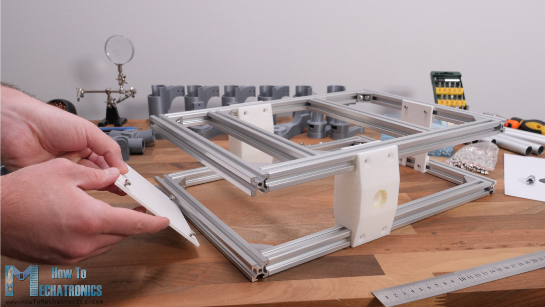
For the rocker joints I used M5 bolts and nuts. The distance from the front profile to the rocker joint needs to be 134mm.
Assembling the Rocker-bogie Suspension
Next, we can insert the main bearings for the rocker-bogie suspension in place. Then, we have the rocker joint shaft which will be attached to the base using an M8 bolt.
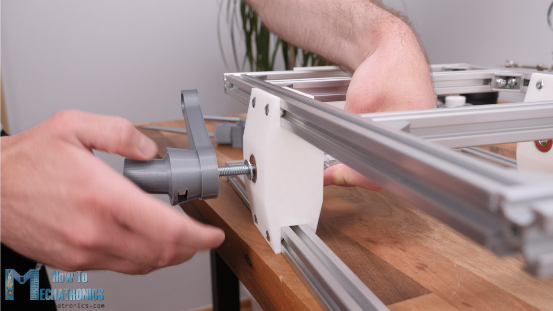
The shaft has a slot where we can insert an M8 nut which is used for securing it to the base. The hole of the shaft is 7.5mm so that we have a tight connection between the bolt and the shaft. In this way we actually reinforce the 3D printed shaft as the bolt itself will carry some of the weight of the rover. This is the most stressed part of the whole assembly as the whole weight of the rover is supported with the rocker shaft. The way we print the parts is very important for their strength.
I initially printed this shaft the easier way, where no support material is need, but the print failed.
In this way the main stress force acts on the layers which are not that strong, but if we print the part sideways, where the stress force will act on the wall contours, the part will be way stronger and won’t fail.
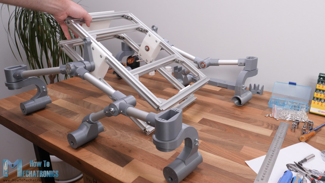
Nevertheless, now we will continue with assembling the rocker-bogie suspension together with the wheel joints and the motor mounts, and later we will attach these sub-assembly to the rocker shafts.
The holes of the parts where the 20mm round profiles go are dimensioned to have a tight fit, so in some cases we need to use a rasp or a sanding paper to make them fit.
Now for properly assembling these parts, we need to make holes in the round profiles at precise locations. For the purpose, first we will mark a straight line on the profile.
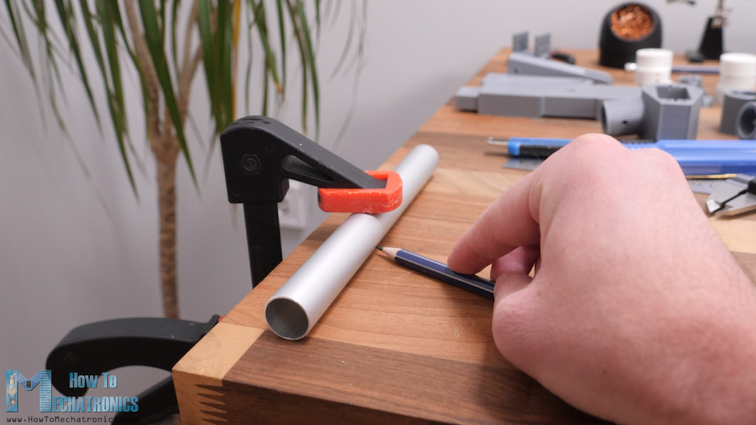
Next, we can insert the profile into the 3D printed part with the marking line passing through the hole of the part. Then we can mark the locations where we need to drill the profile on both sides of that part.
On the opposite side of the profile, we need to repeat the same procedure.
I drilled the holes using a 2.5mm drill, and then using a M3 bolt I made a thread in the profile which we will use for tightening the parts.
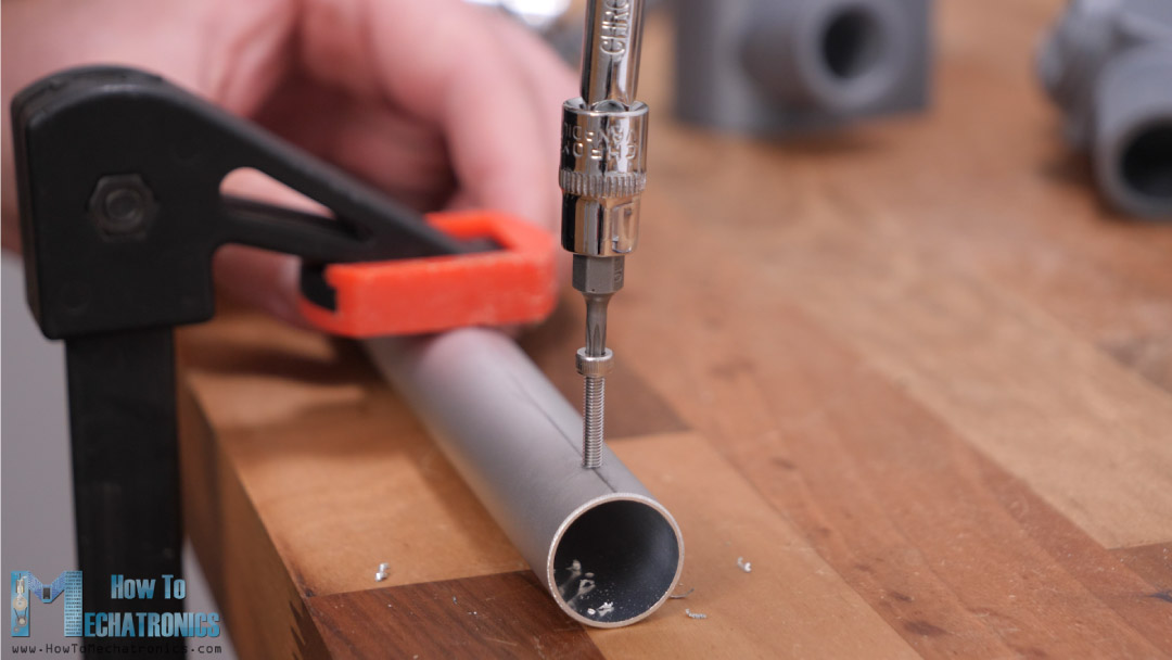
The aluminum profile is softer than the bolt so it’s easy to make the thread with the bolt itself. Following this method for drilling the holes is very important so that at the end all of the parts are positioned as they should be relative to each other.
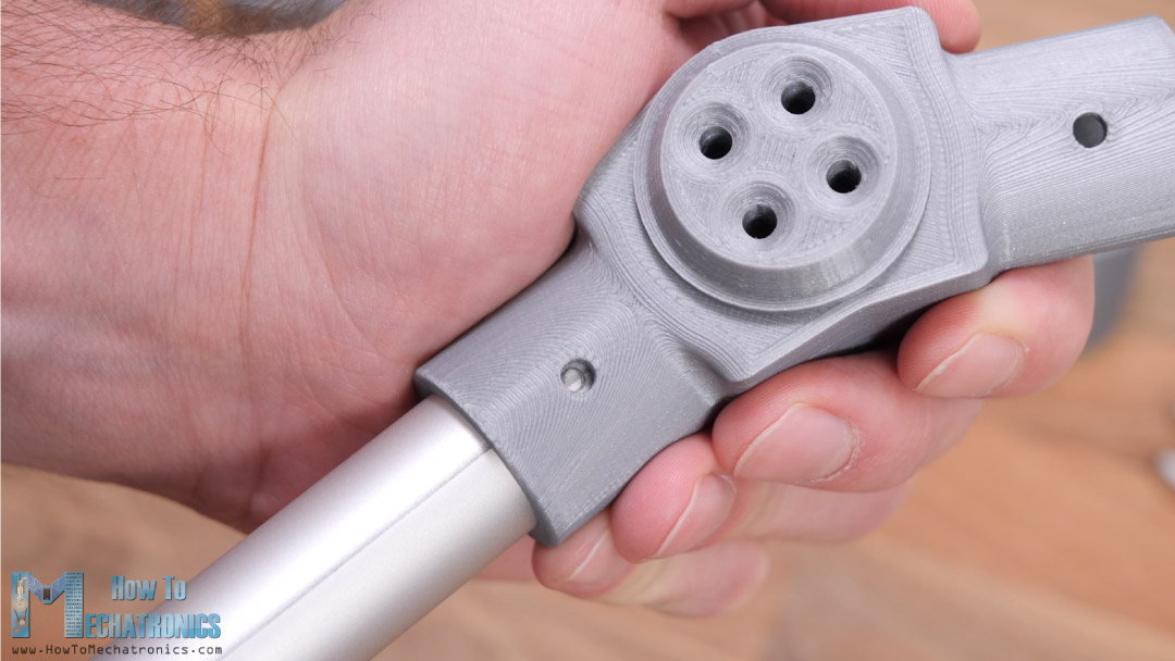
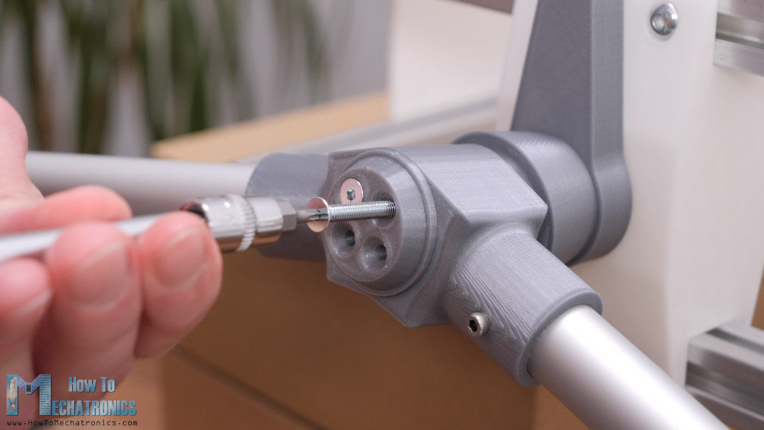
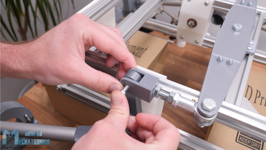
For the bogie joint we also use two bearings and an M8 bolt.
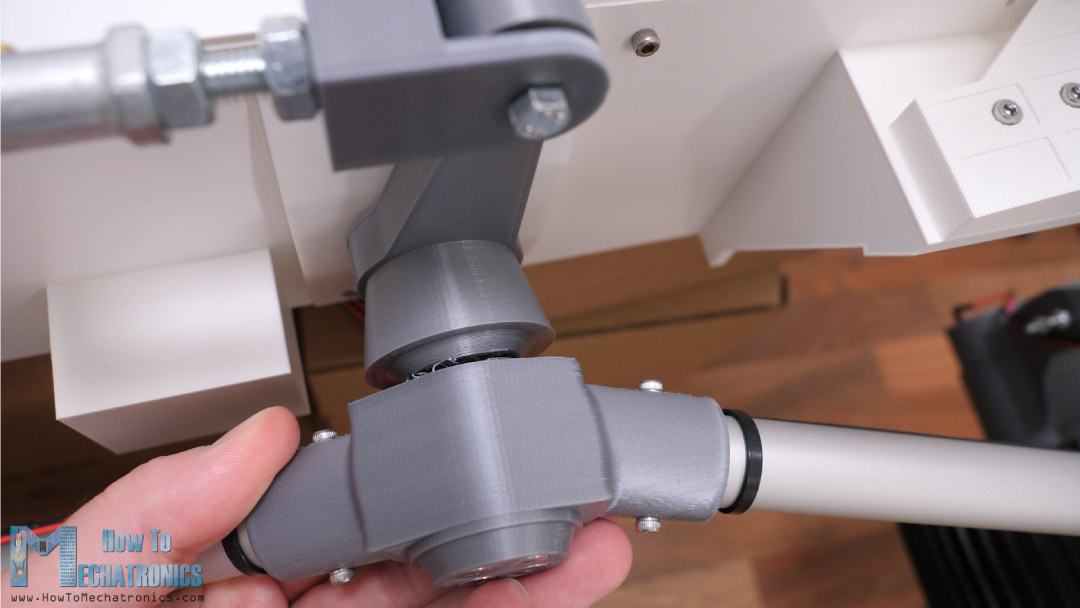
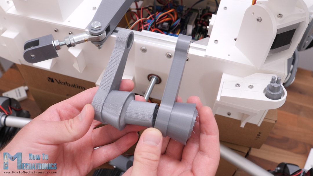
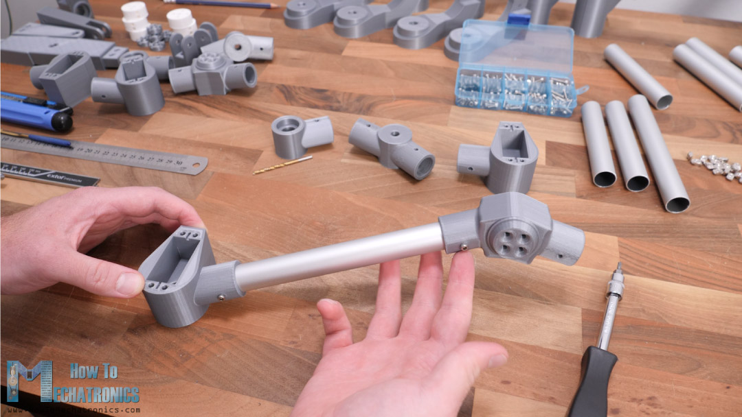
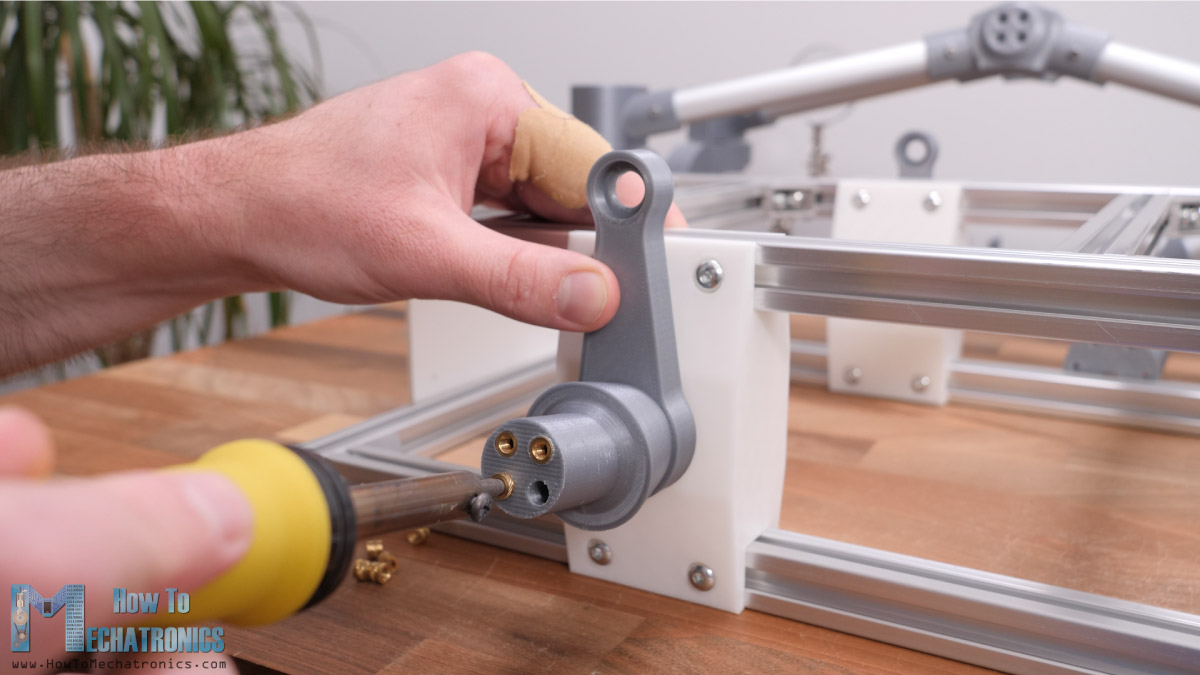
Once we complete the rocker-bogie suspension arrangement we can continue with assembling the steering wheel joints. The steering wheel joint part is composed of two parts bolted together.
For the actual joint or the connection between the servo mount part and the DC motor mount part we use two bearings and an M6 bolt.
At the top side or the head of the bolt we need to attach a servo horn and we do that with the help of this 3D printed coupler and some M3 bolts.
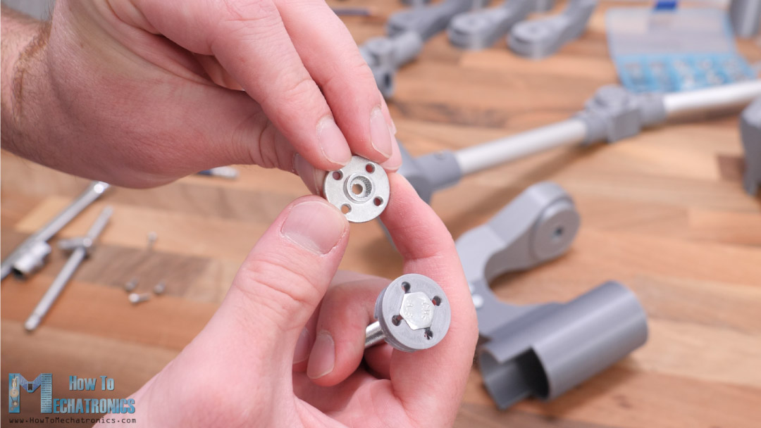
The coupler has a hexagonal slot through which the servo motion will be transferred to the bolt. At the bottom side we can screw the other part of the joint.
We secure this connection with an M6 nut. This completes the steering wheel joint, although later on I will realize that we actually need to add another M6 nut at the bottom and tight it to the other nut.
We need to do this because the motion from the servo is transferred to the DC motor mount part using the nut itself, and if not tighten with another nut the whole joint will unscrew.
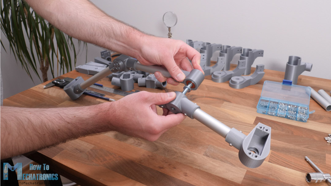
The same procedure goes for the other corner joint. We know we have connected everything properly if we place this assembly on a flat surface and all three motor mounts lay flat or all of them are parallel to each other.
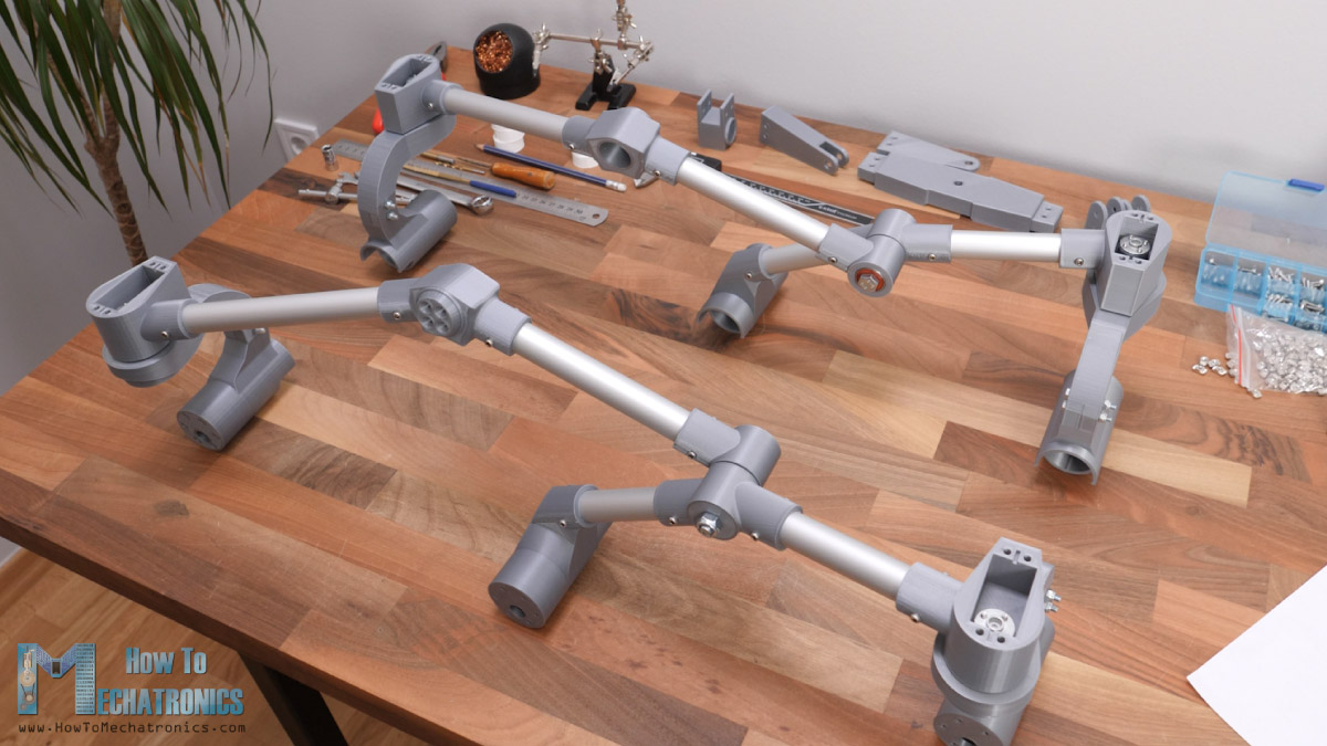
Of course, we are using the same method for assembling the other side. However, we can note here that although some of the parts look identical, they are not the same parts but they are actually mirrored.
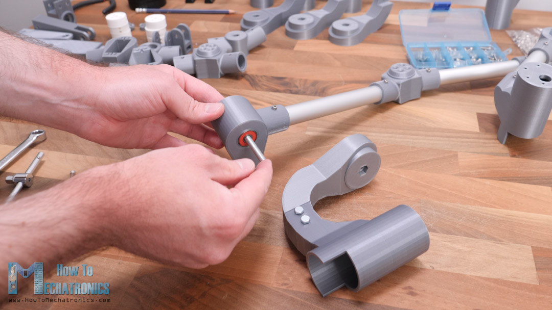
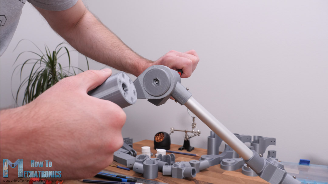
Next, we need to insert these sub-assemblies onto the rocker joint shafts on the base frame or the chassis. Before we do that though, we need to insert some threaded brass inserts in the shaft.
Using a soldering iron, we can easily insert them in place, and so we get a good and reliable threaded holes for securing the suspension sub-assembly. We need four M4 bolts for that purpose.
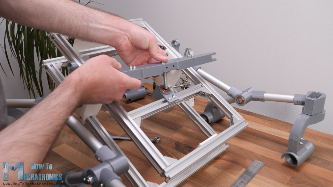
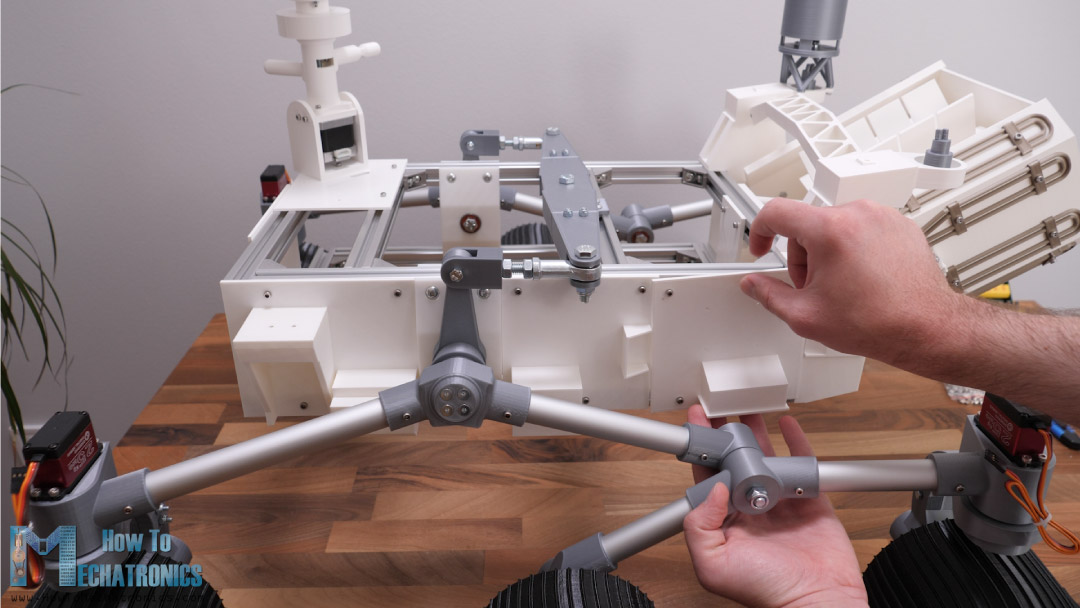
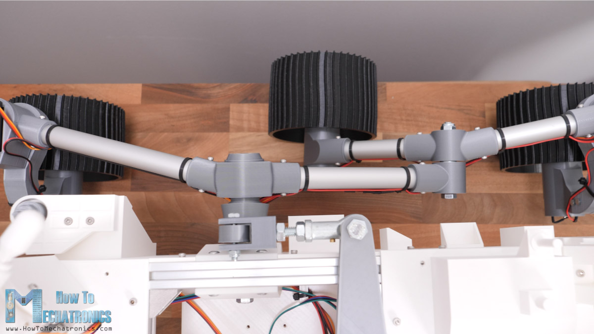
Once we install them on both sides, we can notice that the chassis falls or rotates freely. So, we are actually missing something in order the rocker-bogie suspension to work properly, and that’s the differential.
With the differential, the two rockers are connected to each other and the rover chassis. With this configuration, when one side rotates, the other rotates in the opposite direction thus providing approximately equal wheel contact.
The chassis will have an average pitch angle of both rockers.
Here are all of the parts needed for assembling the differential.
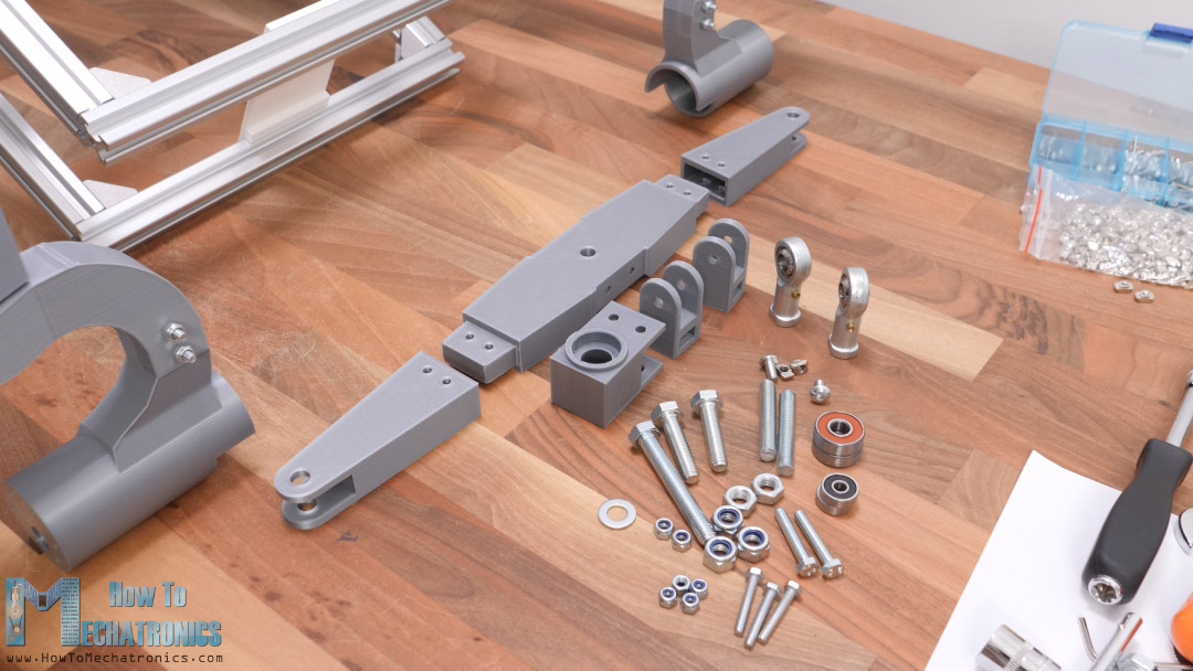
As the differential bar is quite long, I made it out of three pieces bolted together so that we are able to 3D print them even on smaller 3D printers. The differential bar will pivot in the middle of the chassis with a joint made of two bearings and an M8 bolt.
For connecting the differential with the rocker, we need a rod end ball joint. I’m using M8 rod end ball joint and we also need an M8 threaded rod with 50mm length. The threaded rod goes into a 3D printed part which has an M8 nut on one side, and on the other side it goes into the rod end ball joint.
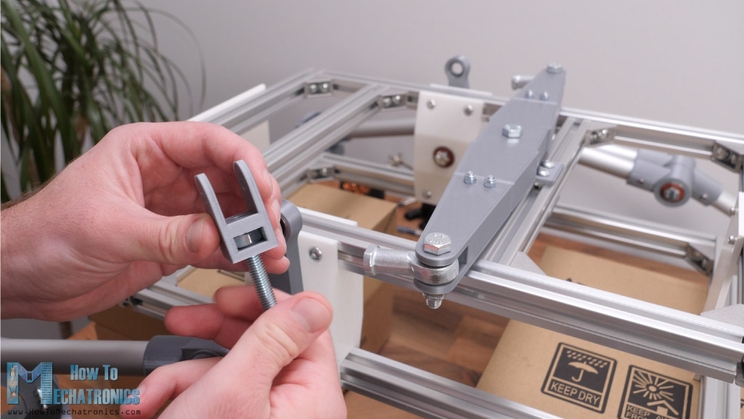
Here we need to adjust the distance between the 3D printed differential link and the rod end which needs to be around 20mm in order the chassis to stay horizontal. For connecting the differential link with the rocker lever, we are using two bearings and an M5 bolt.
We repeat this procedure for the other side as well and with this our rocker-bogie suspension is completed. When one side goes up, the other goes down and vice-versa.
This provides all wheels to be in contact with the ground all the time. The chassis goes only half the motion of the leg, or the chassis has an average pitch angle of both rockers.
See also: Arduino Robot Arm and Mecanum Wheels Platform Automatic Operation
Assembling the Motors for Mars Rover
All right, so next we can move on with installing the DC motors. The motors that I use are 37mm in diameter, operating at 12V and have a gearbox with output of 50RPM.
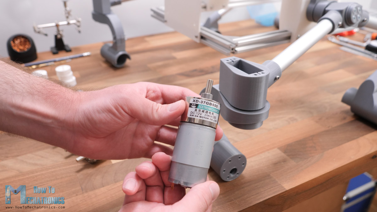
Though I later realized that 50RPM is a bit too much for this rover, so I would suggest choosing 20 or 10 RPM versions.
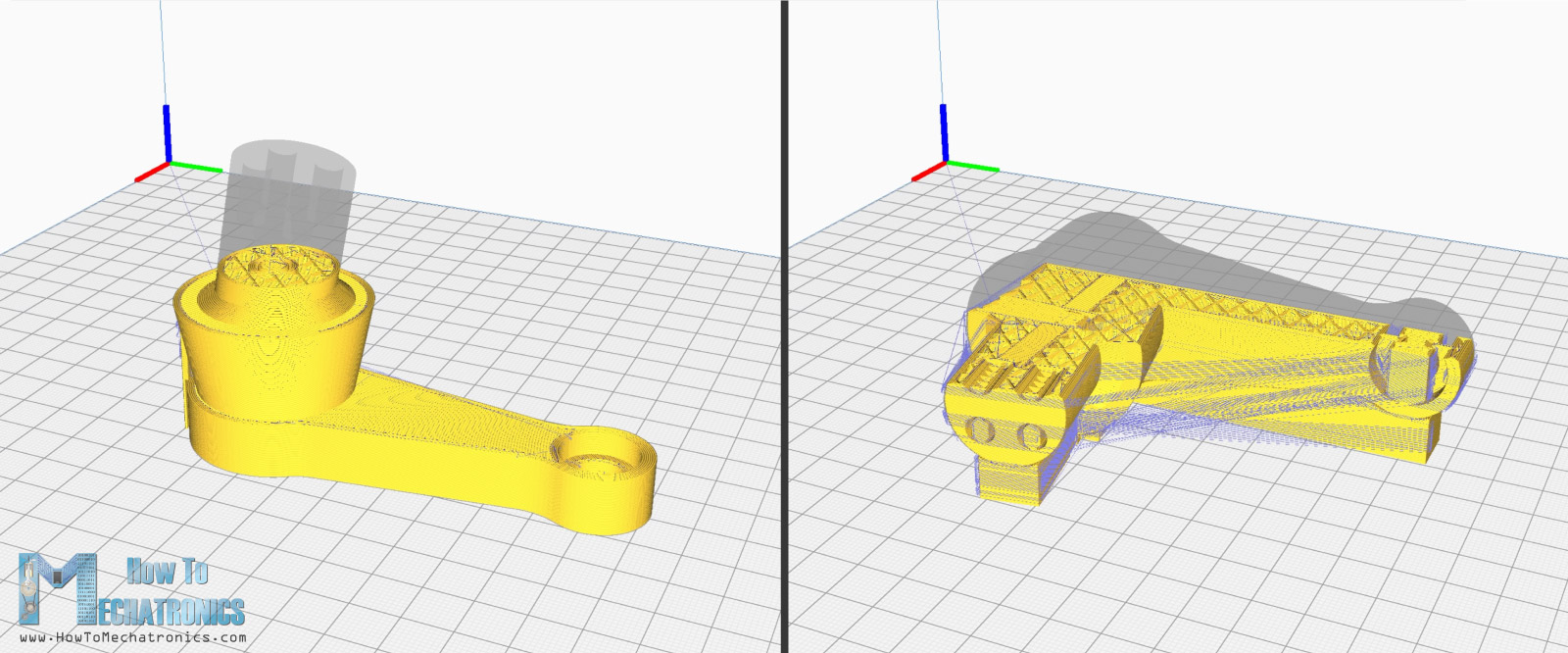
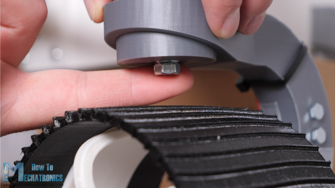
For attaching the wheels to the motors, I made these shaft couplers.
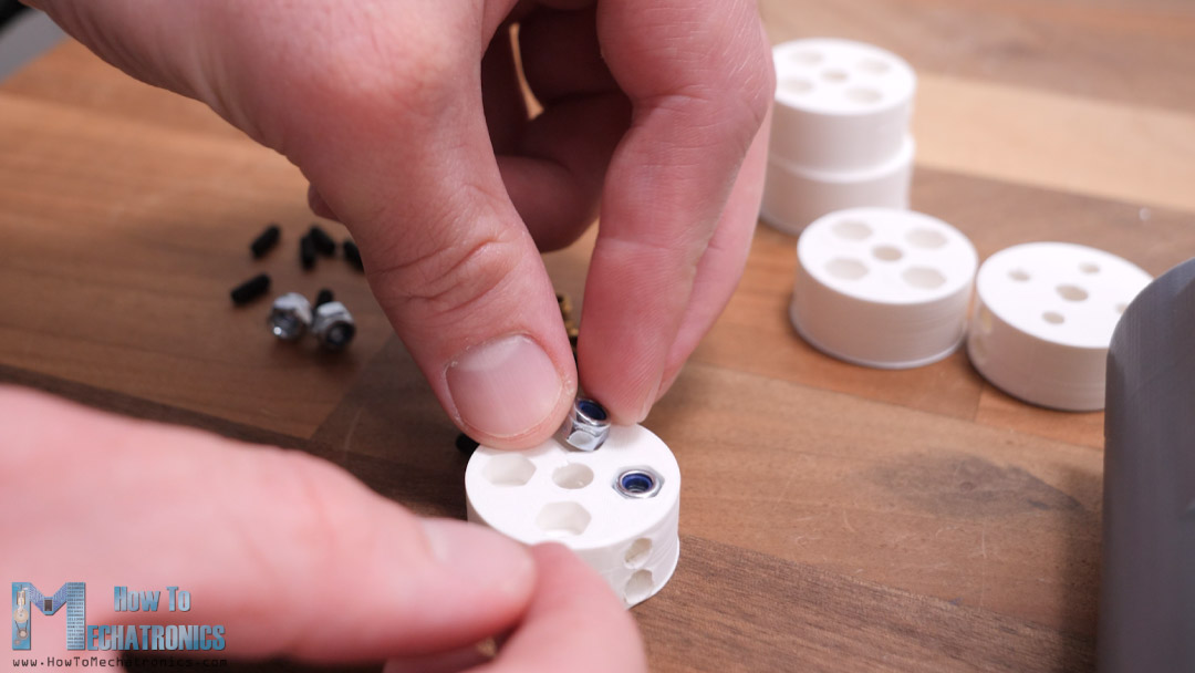
Here we need to install M3 threaded inserts which will be used for securing the coupler to the shaft, and also M4 nuts for securing the wheel to the coupler. When inserting the nuts, we should also add some glue so they stay in place firmly, or use threaded inserts instead.
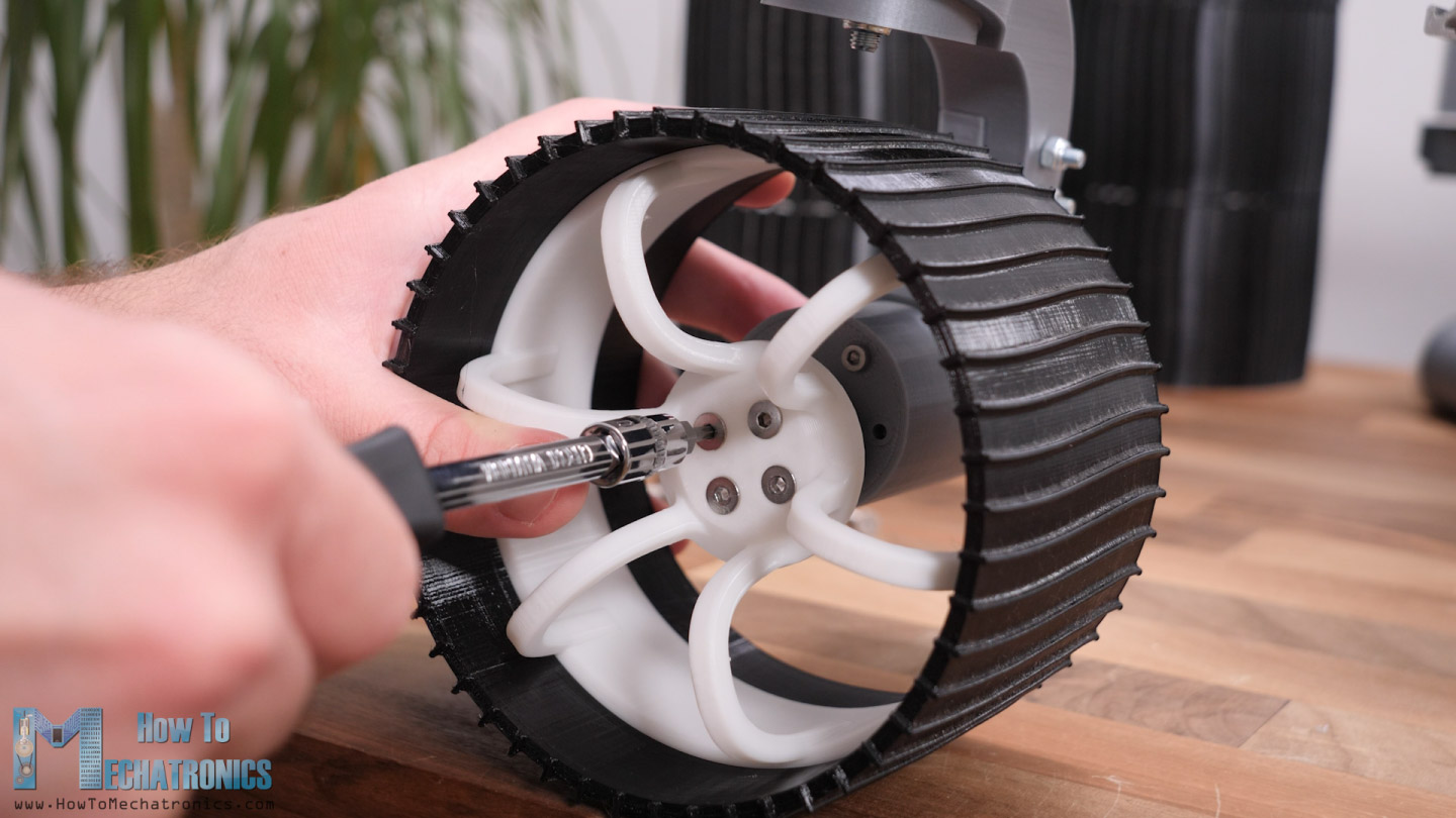
Next, we can attach the wheels. The wheels are composed of two parts. One is the wheel which I printed with flexible filament, but it doesn’t have to be, and the other is the rim printed with normal PLA.
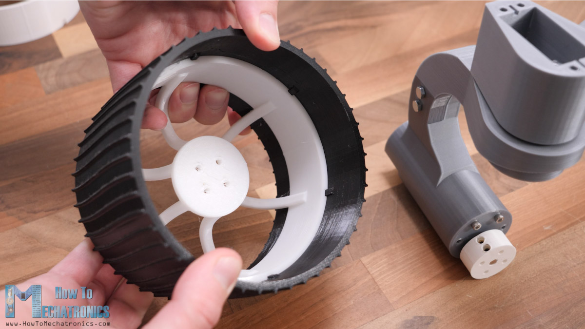
The rim has slots which fit into the wheel and so the power from the motor is transferred to the wheel. We can add few drops of glue at the slots to have them more secured. Finally, we can attach the wheels to the shaft couplers or the DC motors using 4 M4 bolts.
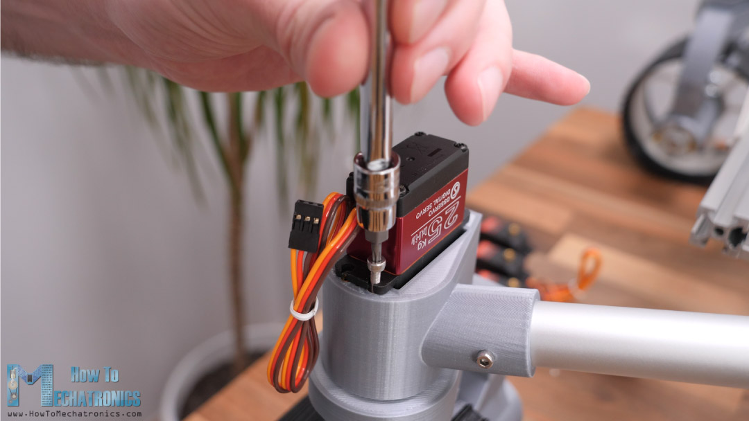
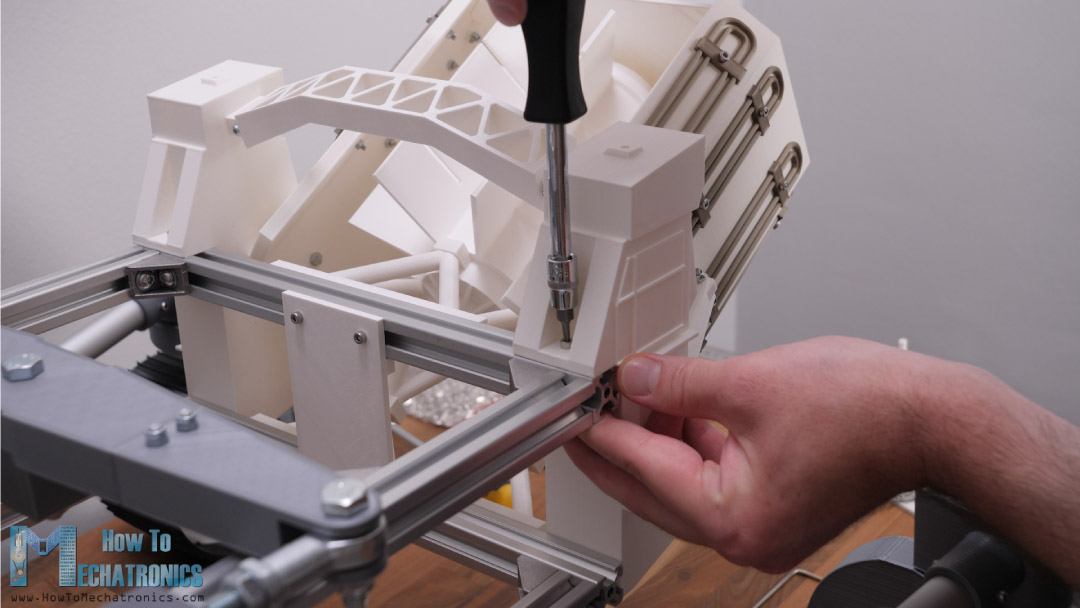
All right, so next we can install steering servo motors. I’m using high torque digital servos with 25kgcm torque and operating voltage from 4.8 to 6.8V. For securing the servos in place, we use four M3 bolts which go into the M3 threaded inserts in the servo mount 3D printed part.
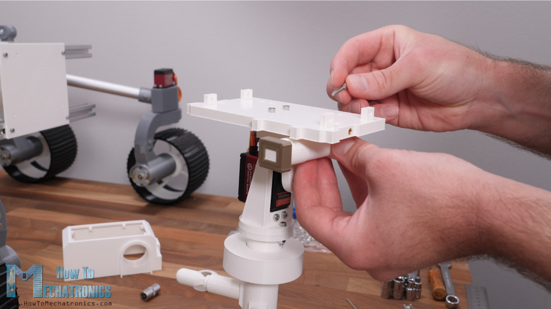
Assembling the Camera Unit
Next, we can assemble the cameras unit. For the panning the camera I decided to use a NEMA 17 stepper motor, but you can change this any use any other type motor here.
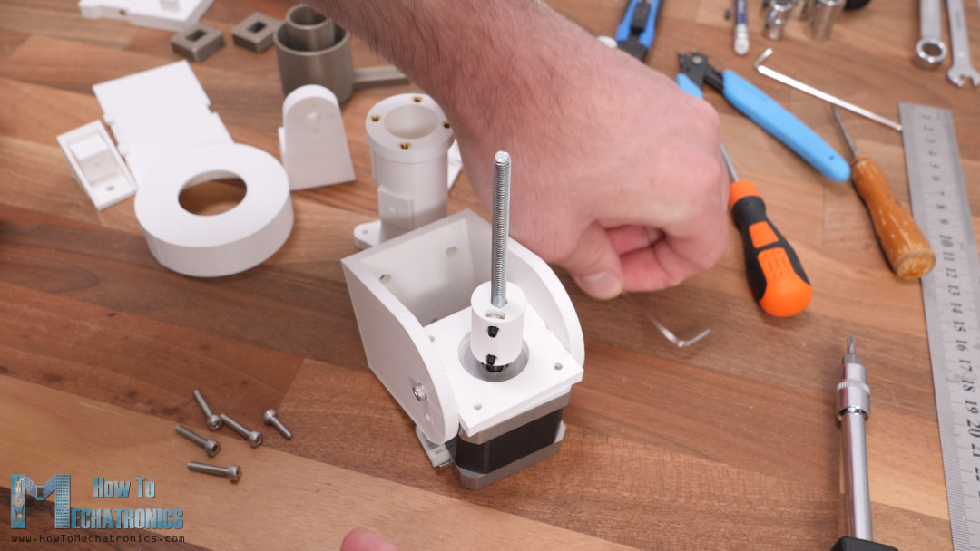
The motor motion is transferred to the upper section using an M5 threaded rod which is connected to the motor with a 3D printed shaft coupler, and on the other side we use a bearing and two nuts to secure the threaded rod to the moving element. For tilting the camera I’m using a servo which is the same as the one we use for the steering wheels.
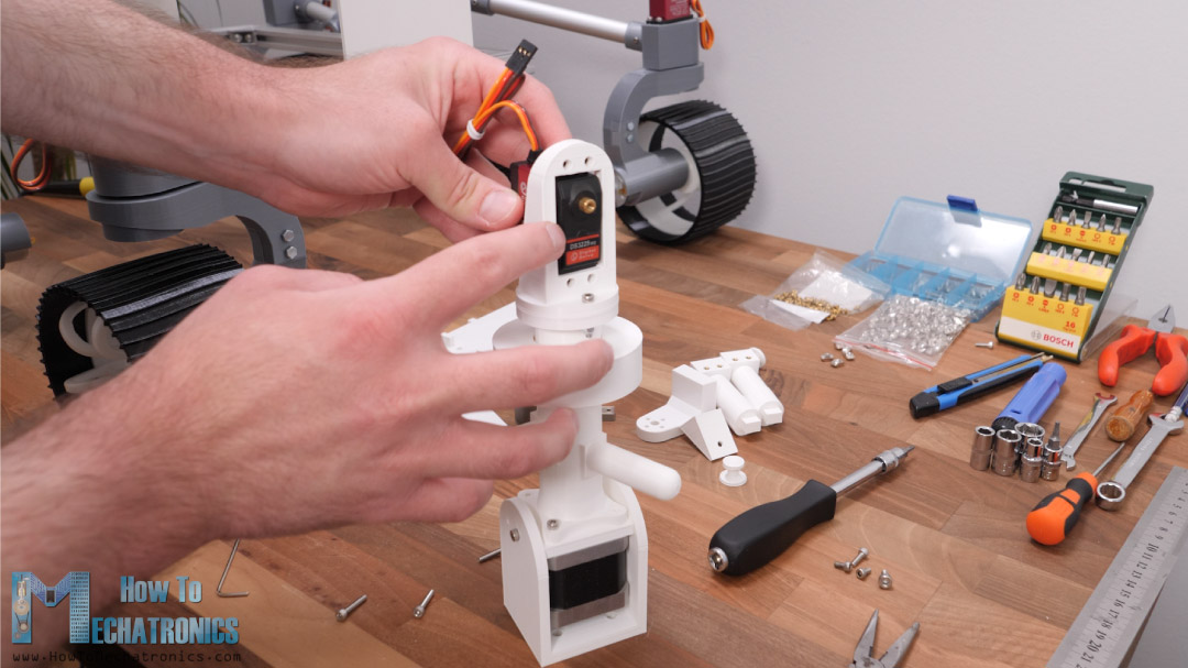
Many of the parts here on the camera unit are not functional and they are present just to match the appearance of the real rover. For assembling these parts, we need various M3 bolts and some threaded inserts.
However, I will also install a real FPV camera here. I made a custom holder for it so I can mount it on the housing of the camera unit. The camera is easily accessible from the top which we close it with a snap-fit cover. Here’s the final appearance of the camera unit.
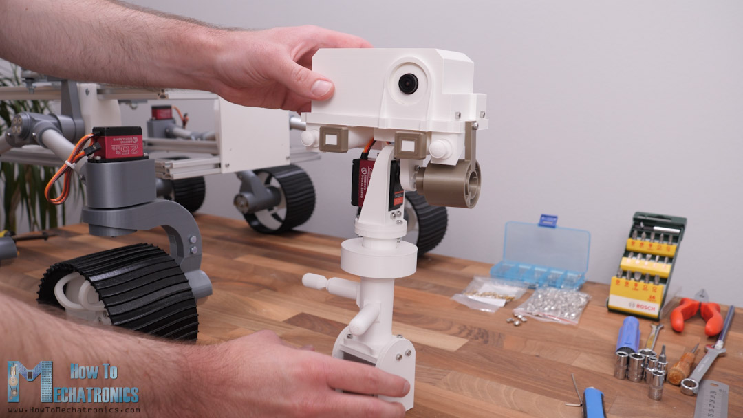
I mounted this whole camera sub-assembly in the front right corner of the chassis.
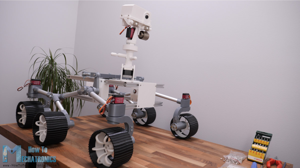
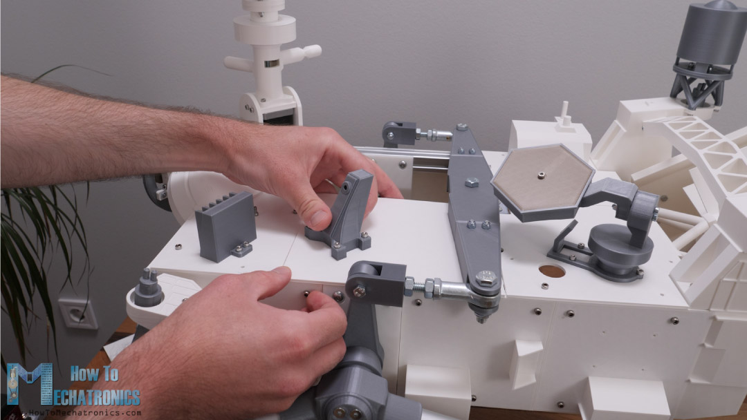
At this point, we can continue either with assembling the rest of the 3D printed parts, which are actually not functional but only to match the appearance of the real rover, or connect the electronics components and get the rover working. I decided to assemble all 3D printed parts first and then do the electronics.
Assembling the rest of the rover
Just like I said, the following parts are just for matching the appearance of the rover so I won’t go in details how to assemble them. You can see how everything needs to be connected from the 3D model.
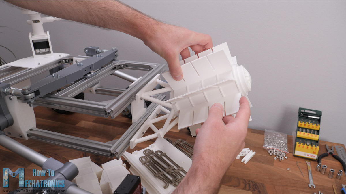
I actually put a lot of effort designing these parts, paying attention to details in order everything to looks good.
These parts are also quite big and take some time to 3D print them.
Here’s a quick view how I installed them.
The last two top panels in the middle of the rover are designed to a snap-fit in the rover.
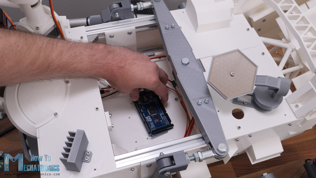
They will actually act as a hood which can be easily removed as the electronic components will be located in this area.
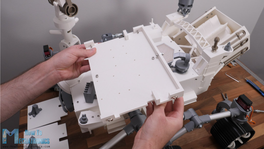
The electronic components holder is made out of two 3D printed parts bolted together and it goes to the bottom frame of the chassis.
Electronics
All right, so now we can continue with the electronics. First, we need to measure how much wire we need for each motor. I soldered the wires directly on the motors as I didn’t have proper motor connectors. I used heat shrink tubing for isolating the connectors.
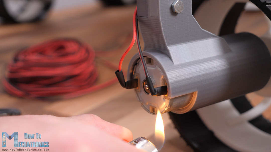
With the help of some zip ties, we can guide and keep clean the wires.
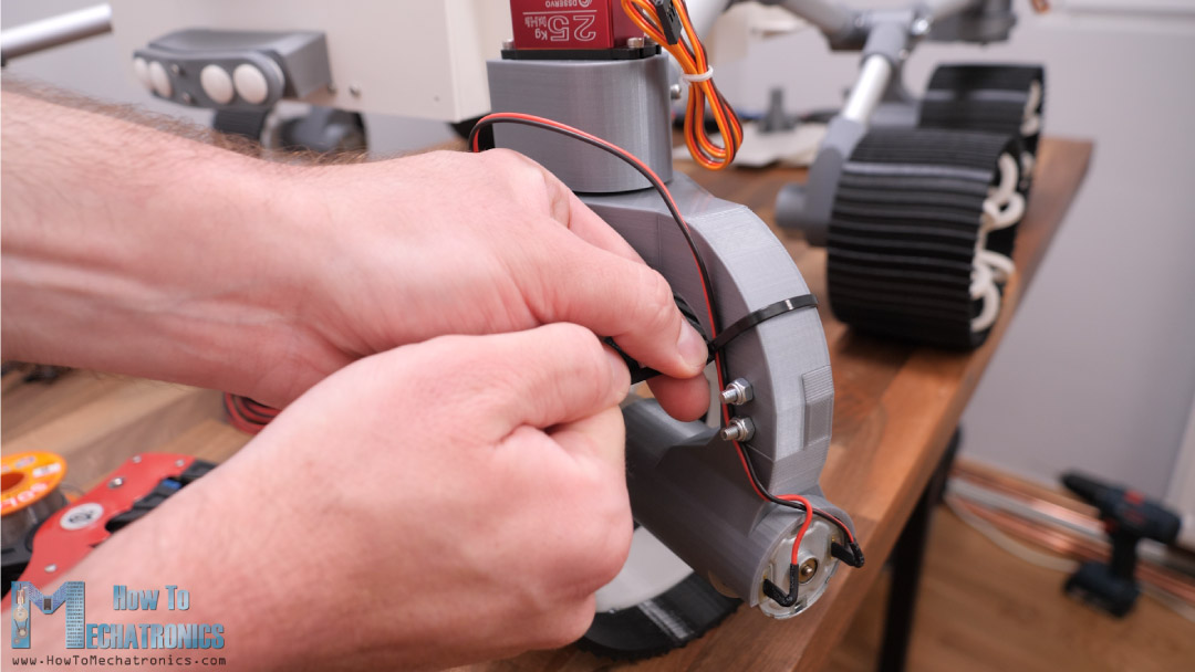
For the servo motors we can use servo extension wires to extend the wires to the electronics compartment. The electronics mount part has slots through which we can pass the wires to get the middle of the rover.
Overall, I think the wiring came out quite clean with the wires passing behind the visible parts.
See also: SCARA Robot | How To Build Your Own Arduino Based Robot
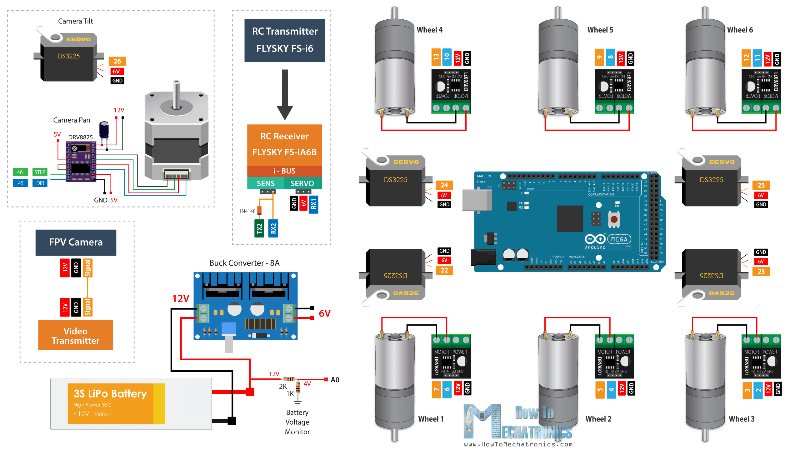
DIY Mars Rover Circuit Diagram
Let’s take a look at the circuit diagram of this rover now, and see how everything needs to be connected.
You can get the components needed for this project from the links below:
- DC Motor 12V 37mm …….……………….… Amazon / Banggood / AliExpress
- Digital Servo 25kg ……………………………. Amazon / Banggood / AliExpress
- DRV8871 DC Motor Driver ………………. Amazon / Banggood / AliExpress
- Stepper Motor – NEMA 17………………… Amazon / Banggood / AliExpress
- A4988 Stepper Driver………………..…..… Amazon / Banggood / AliExpress
- Arduino MEGA…………………….…..……… Amazon / Banggood / AliExpress
- DC-DC Buck Converter ……………………. Amazon / Banggood / AliExpress
- 3S LiPo Battery ………………………..……….. Amazon / Banggood / AliExpress
- XT60 Connector ……………………………… Amazon / Banggood / AliExpress
- FLYSKY RC Transmitter ………………….. Amazon / Banggood / AliExpress
- FPV Camera and Video Transmitter …. Amazon / Banggood / AliExpress
- FPV Receiver by you choice
Disclosure: These are affiliate links. As an Amazon Associate I earn from qualifying purchases.
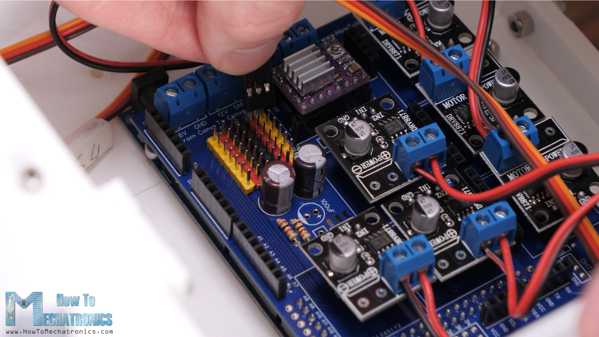
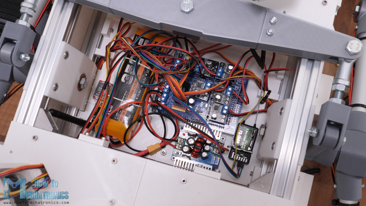
For driving the six DC motors, we are using six DRV8871 DC motor drivers which support PWM control and up to 3.6A of peak current. The DC motors operating voltage is 12V, with rated current of 1A and stall current of 3A. For powering the rover I’m using a 3S LiPo battery which provides around 12V.
The servos on the other hand need from 4.8 to 6.8V, so therefore we need an DC-to-DC converter which will convert the 12V to 6V. The converter needs to be able to handle around 8A of current, as the servos that we are using are quite powerful and have a stall current of around 2A. For driving the camera unit stepper motor, we can use an A4988 or DR8825 stepper driver. Using two resistors we can make a simple voltage divider through which we can monitor the battery voltage.
The RC receiver is power with the 6 volts coming from the buck converter, and the FPV camera and its video transmitter are powered with the 12V from the battery.
Custom PCB
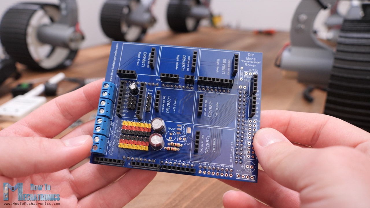
In order to keep the electronics components organized I designed a custom PCB for this DIY Mars rover.
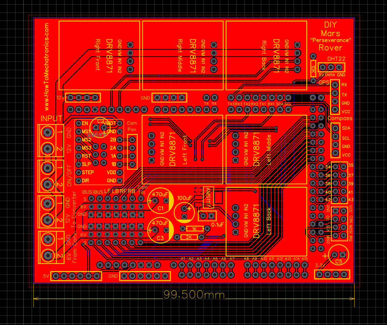
This PCB will actually act as an Arduino MEGA shield as we will be able to directly connect it on top of the Arduino MEGA board. In addition to the motor drivers, I included a 3.3V voltage regulator and a dedicated NRF24L01 connection in case you want to control the rover using that module, as well as connections for an DHT22 sensor, compass, I2C, serial communication, 12V, 5V, 3.3V and GND connections. Actually, I futureproofed this PCB for upgrading the rover’s functionalities.
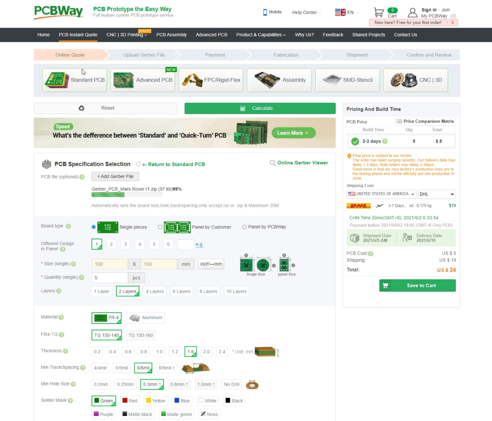
I ordered the PCB from PCBWay. Here we can simply upload the Gerber file, choose the properties of our PCB, and order it at a reasonable price.
I didn’t change any of the default properties except for the PCB color which I chose to be blue in order to match with the Arduino board. You download the Gerber file here below, or from the PCBWay projects sharing community through which you can also directly order the PCB.
Here’s you can download the Gerber file for this DIY Mars Rover PCB:
Nevertheless, after several days the PCB arrived. The quality of the PCB is great, and everything is exactly the same as in the design.
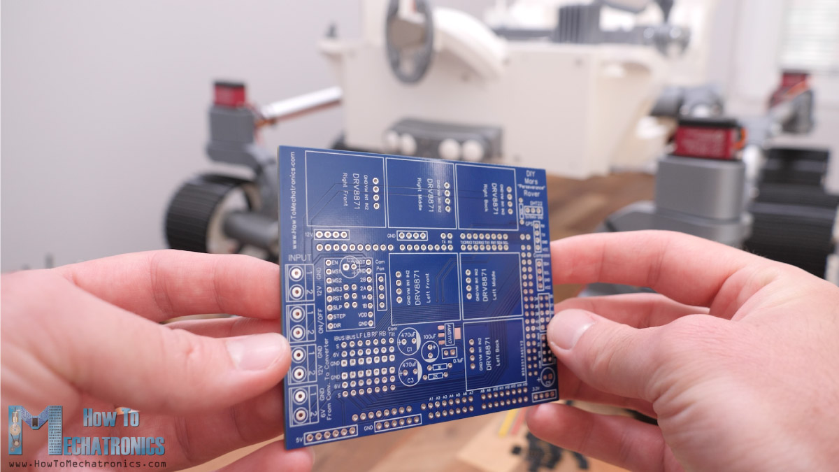
Assembling the PCB is pretty straight forward as everything is labeled. I started with soldering the pin headers at the bottom of the PCB, for the Arduino MEGA connection and then continued with top side. I actually used pin headers for all connections, because it gives flexibility to make changes if something doesn’t work properly. I didn’t solder the 3.3V voltage regulator as well as some free Arduino pins, as I wasn’t going to use them now anyway.
Once finished with the PCB assembly I secured the Arduino board to the electronics mount part using two bolts and added the PCB to it.
Then I connected each motor to their drivers and put them in place in the PCB. The servos go in their appropriate servo pins, as well as the stepper driver for which I used one jumper for selecting 1/8th stepping resolution.
For the radio communication I’m using the FLYSKY RC transmitter and receiver which are really affordable and work great.
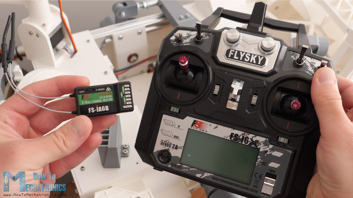
For connecting the receiver to the Arduino, we can use servo extension cables as we need three wires, VCC, GND and the Signal pin. The receiver communicates with the Arduino through an I-BUS and the serial port. If we want to send data back from the receiver to the transmitter, in our case for monitoring battery voltage, we also need to connect the sensor I-BUS of the receiver to another Arduino serial port.
The buck convertor is secured in place using two bolts, and for securing the LiPo battery I’m using two rubber bands so in that way I can easily remove the battery for charging.
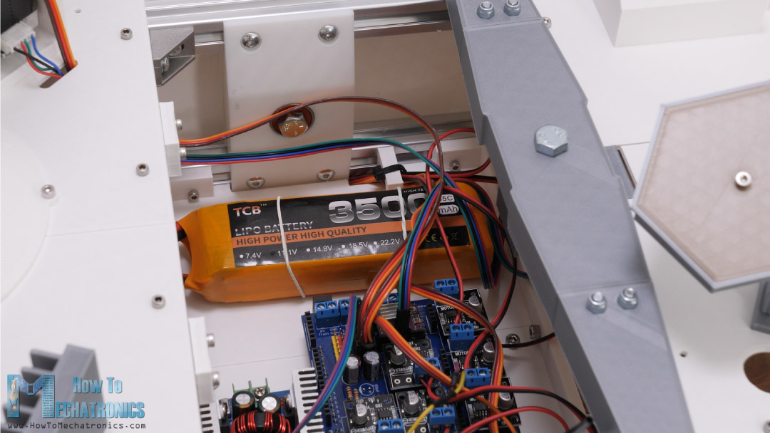
The power switch goes in the back right panel of the rover. I used 20-gauge wires for these connections as the current flow through them might get up to several amps when the rover is fully engaged. Make sure you double check your connections with these wires because if you connect something wrong you might fire up things.
Lastly, we can connect the FPV camera to a 12V power supply and connect video signal wire to the video transmitter which also needs to be powered with 12V. With this we are done with the electronics.
We can put back the cover panels in place and we are done with this DIY Mars Rover. Actually, we are almost done, as we need to give life to this machine now, or program the Arduino.
Programming the DIY Mars Rover – Arduino Code
Here you can download the Arduino code for this DIY Mars Rover project:
Code overview
So, using the IBusBM library we read incoming data from the RC Transmitter.
// Reading the data comming from the RC Transmitter
  IBus.loop();
  ch0 = IBus.readChannel(0);
  ch1 = IBus.readChannel(1);
  ch2 = IBus.readChannel(2);
  ch3 = IBus.readChannel(3);
  ch6 = IBus.readChannel(6);Code language: JavaScript (javascript)
Then we convert these values into a turning radius to right value, turning radius to left value and rover speed from 0 to 100%.
// Convertign the incoming data
  // Steering right
  if (ch0 > 1515) {
    r = map(ch0, 1515, 2000, 1400, 600); // turining radius from 1400mm to 600mm
  }
  // Steering left
  else if (ch0 < 1485) {
    r = map(ch0, 1485, 1000, 1400, 600); // turining radius from 600mm to 1400mm
  }
  // Rover speed in % from 0 to 100
  s = map(ch2, 1000, 2000, 0, 100); // rover speed from 0% to 100%Code language: JavaScript (javascript)
We use the turning radius “r” value for calculating the steering wheels angles as well as the speed of the wheels.
void calculateMotorsSpeed() {
  // if no steering, all wheels speed is the same - straight move
  if (ch0 > 1485 && ch0 < 1515) {
    speed1 = speed2 = speed3 = s;
  }
  // when steering, wheels speed depend on the turning radius value
  else {
    // Outer wheels, furthest wheels from turning point, have max speed
    // Due to the rover geometry, all three outer wheels should rotate almost with the same speed. They differe only 1% so we asume they are the same.
    speed1 = s;
    // Inner front and back wheels are closer to the turing point and have lower speeds compared to the outer speeds
    speed2 = s * sqrt(pow(d3, 2) + pow((r - d1), 2)) / (r + d4);
    // Inner middle wheel is closest to the turning point, has the lowest speed
    speed3 = s * (r - d4) / (r + d4);
  }

  // speed value from 0 to 100% to PWM value from 0 to 255
  speed1PWM = map(round(speed1), 0, 100, 0, 255);
  speed2PWM = map(round(speed2), 0, 100, 0, 255);
  speed3PWM = map(round(speed3), 0, 100, 0, 255);
}

void calculateServoAngle() {
  // Calculate the angle for each servo for the input turning radius "r"
  thetaInnerFront = round((atan((d3 / (r + d1)))) * 180 / PI);
  thetaInnerBack = round((atan((d2 / (r + d1)))) * 180 / PI);
  thetaOuterFront = round((atan((d3 / (r - d1)))) * 180 / PI);
  thetaOuterBack = round((atan((d2 / (r - d1)))) * 180 / PI);
}Code language: JavaScript (javascript)
As I mentioned earlier, we are using the Ackerman steering geometry for calculating them. These values are then used for controlling the servos using the ServoEasing library which provides smoother servo movements.
// Servo motors
    servoW1.startEaseTo(97 - thetaOuterFront);
    servoW3.startEaseTo(97 + thetaOuterBack);
    servoW4.startEaseTo(94 - thetaInnerFront);
    servoW6.startEaseTo(96 + thetaInnerBack);Code language: JavaScript (javascript)
For controlling the DC motors using the analogWrite() function which actually sends PWM signal to the DC motor drivers.
// Motor Wheel 1 - Left Front
      analogWrite(motorW1_IN1, speed2PWM);   // PWM value
      digitalWrite(motorW1_IN2, LOW); // ForwardCode language: JavaScript (javascript)
Overall, the code is not that complicated as the rover itself doesn’t have complicated functions. However, I do plan in future videos to add more functions to this rover, like GPS navigation, various sensors, robotic arm, soil collecting mechanism and so on.
I hope you enjoyed this project and learned something new. Feel free to ask any question in the comments section below and check my Arduino Projects Collection.
Hey Dejan,
Your project is truly incredible.
Could you please tell me which capacitor you are using for the C2 on the middle left hand side near the 12V input? I guess it might be a 100um?
Best regards
Hey, thank you!
Yes, the value for the C2 can be 100um or anything around that value. It’s for stabilizing the voltage on the A4988 driver.
Hi Dejan,
I started by printing the white parts. PCB has been ordered. And the hardware has also been ordered. On my second printer (AnetA8 Plus) I started with TPE. I’ve never been happy with this. Not even now. Can you give me the basic settings used? Such as nozzle temperature, speed, fan speed, and line width. I look forward to building in totality. First the functional parts and if everything works I’ll see what happens. thank you very much for this wonderful project. Kind regards, Jan
Hi, glad to hear it, I hope you will have fun building it! As for the TPE printing settings, it’s best to find suggestions for your printer and the filament itself.
I have the Rover powered up now. Steering is working great. Something is up with the motors though. Doesn’t seem to respond to throttle or direction inputs.
Hi, glad to hear it your Rover is powered up! It’s kind a hard to guess what could be the problem without providing some more info. There are many things that could be a problem, it’s a big and complex project.
You might not be getting the right commands from the transmitter, or your motors or drivers might not working properly. You should check them with a simple code whether they work.
How long did you take from concept to production of the rover? And how much did it cost?
It took me around 4 months. As for the cost I’m not sure, I didn’t do the math. 🙂
Dejan, wondering if there is a supplier for all the 3D plastic parts. I have a top of line 3D printer and LOTs of filament, but it could be months before I could get all the parts printed!
Well I printed the parts my self. Yeah, it takes time.
hello, I hope you are still following this fantastic project, I am building the rover and I am waiting for the pcb to do a first dynamic test, so far I have found the project extremely refined, more than I thought! I also shared the construction on my italian 3d printing forum…i have a question for you,the nut that blocks the “wheel structure” on the servo seems to loosen too easily, have you noticed this problem too? how can i fix it?
Thanks, glad to hear it, I hope you enjoy building it!
Yeah, that’s true, that pivot joint design is not the best. Try to use two nuts or glue the nut maybe?
Super work of you , I found the 4 variables d1,d2,d3,d4 in steering radius calculation, Can u explain How did u find the values of d1,d2,d3,d4
Thank you! Here you can find more info about the Ackerman steering radius calculation: https://github.com/nasa-jpl/open-source-rover/blob/master/software/Software%20Controls.pdf
Hi, i have built the main chassis, all works now. i did find that selecting stick mode 4 on the radio then mapping the forward and reverse to a switch made the whole thing work.
Are you going to do and update for something like a pixhawk for automatous control.
and on your PCB you have a few things like GPS and another Sbus input?
Mike
Hey, glad to hear it’s working. Well to be honest I don’t think I’m going to make updates anytime soon. I got a lot of other projects to do, so no time for it.
Hi Dejan, I am making good progress with my rover. Tomorrow the last vendor parts will arrive and 3D printing functional parts will be finished by Wednesday. One question concerning RC: Is it also possible to use sBus in place of iBus (I already own some Spektrum brand transmitters and receivers for my RC planes)? Which change has to be made to the Arduino programming?
Best regards
Chris
Hi Dejan, so grateful for that awesome project. Amazing work. I have already printed quite a few parts and cut the aluminium profiles. There is one measure I am confused with (most probably I have missed it somehow): What is the position of the rear crossbar for the differential?
Best regards
Chris
Hey, thanks, glad to hear it! You are right, I haven’t specified that dimension. It’s 133mm from the back profile.
Hi Dejan, I am making good progress with my rover. Tomorrow the last vendor parts will arrive and 3D printing functional parts will be finished by Wednesday. One question concerning RC: Is it also possible to use sBus in place of iBus (I already own some Spektrum brand transmitters and receivers for my RC planes)? Which change has to be made to the Arduino programming?
Best regards
Chris
Hi,
Looks like an awesome project! I just have a question about 3D printing the parts. I downloaded the RAR file which I then extracted to get the STL files. I am just wondering the quantity of each of the files I need to get all the parts.
Thanks!
Hey, thanks!
Well, you will have to take a look the model for that, or take notes from the video of the actual model. Sorry about not having a detail list about it.
Cheers!
What an incredible and thorough guide + video – thank you for inspiring and sharing. What’s the role of the capacitors on the PCB?
Thanks! The capacitors are for increase the stability of the power for the servos.
Can you share the Solid Works assembly file so that all the parts fit together ? 🙂
Thank you!
Hey, the assembly file is already included in the Solidworks files folder.
Super excited for this project. I’m looking forward to testing if i can insert a pixhawk autopilot where you have the RC reciever. Waiting on arduino code before i pull the trigger on grabbing the motor shield.
My background is DfAM, less mechatronics and programming so this project is super helpful for another curiosity inspired rover I am building. I’m looking forward to building this one to drive alongside the one i am designing (big differences is modular payload bays and an internal to the chassis differential mechanism). Its a great opportunity to learn. I have been loving the how-to-mechatronics youtube videos and can’t thank you all enough for the outstanding work you do with STEM education and inspiring the next generation.
I might borrow some solutions from your build, mind if i link back as a derivative when it comes time to post?
Hey, glad to hear you found this project and my videos helpful. Yeah, pixhawk autopilot would be awesome upgrade. Sure, you can use my build and link back is always welcome. Cheers!
Whaou, this is a nice project and easier to make than the Sawppy I guess… congratulation and thank you for sharing!
Would you please disclose the calculation, at least the dimensions of the aluminium tubes and profile needed.
I see 226.96mm between two center points for the rear wheels, but with the plastic holders I guess it would be slightly less. I am really curious how you calculated that part, thanks for your help already.
Good day,
Ice
Hey, thanks! Just like I said in the video the dimensions come from the real Mars rover 3D model, which I scaled to have a wheel diameter of 130mm. According to these dimensions and the servos and DC motors, I made the 3D model, so I didn’t do any calculations for it. I will upload the exact tubes and the profiles dimensions that I used soon.
Thank you that would be much appreciated
Friend, the aluminium tube can be replaced by carbón fiber tuve? Same diameter?
Sure, you can use any kind of tube or rod with that diameter. Or you can even use different diameter in case you modify the parts, as the Solidworks files are available and you can change the parts diameter easily.
Nice work! Looks like about 1/4 scale?
Thanks! Yes, it’s 1/4 scale.
I am missing its pair INGENUITY!!
this was most important and exciting features of perseverance… because for the first time humans took flight on the other planet..
True, but hey we can build that one too 🙂
Good job..i like your project .congratulations
If you have an interactive arm, you can do more things, such as sample collection.