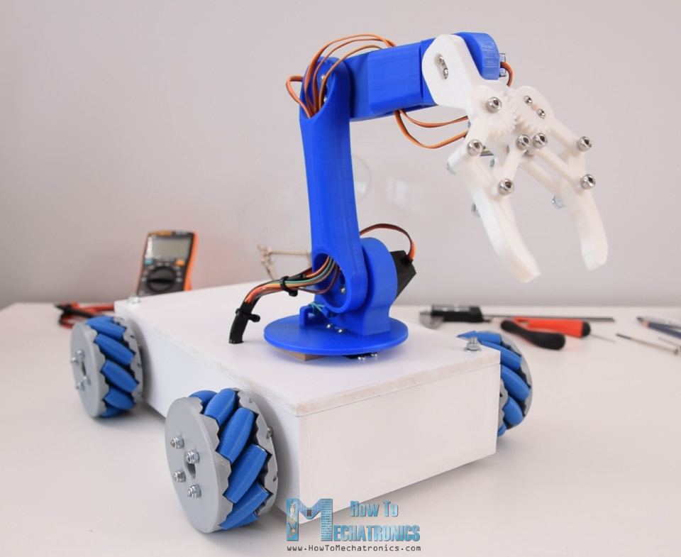
In this tutorial I will show you how I made my Mecanum Wheels Robot Platform from my previous video, to work together and operate automatically with my 3D printed Robotic Arm, also an Arduino project from one of my previous videos.
You can watch the following video or read the written tutorial below.
Overview
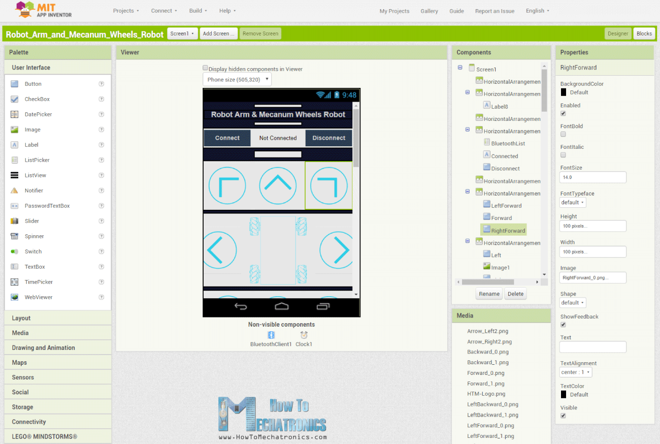
So, we can control the Mecanum wheels robot with the custom-build Android application the same way as explained in the previous video. In addition to that, now the app also has buttons for controlling the robot arm.
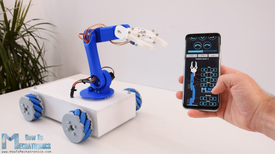
The original robot arm control app actually had sliders for controlling the robot joints, but that was causing some problems with the arm stability. In this way the arm works much better, so therefore I will provide this updated version of the robot arm control app and the Arduino code to the original robot arm project as well.
Nevertheless, the coolest feature of this robot is the ability to store the movements and then automatically repeat them.
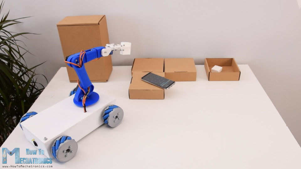
Using the Save button, we can simply store the positions of the motors for each step. Then we just need to click the Run button and the robot will automatically repeat the stored movements over and over again.
Building the Arduino Robot
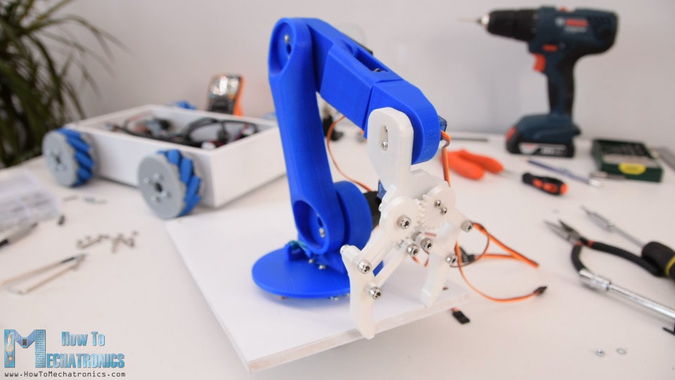
Ok, so here I have the Mecanum wheels platform already assembled and you can find all details about it in my previous video.
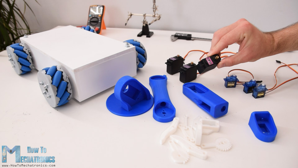
Also, here I have the 3D printed parts of the robot arm and the servo motors and now I will show you how to assembly them.
3D Model and STL Download Files
Here’s the 3D model of this project.
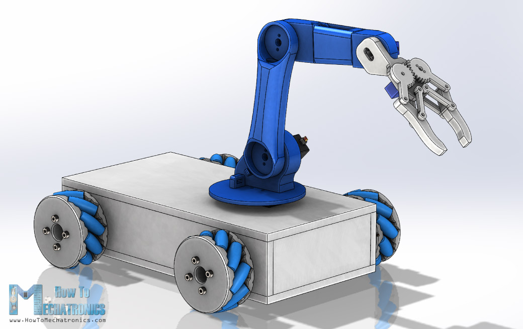
You can get this 3D model, as well as the STL files for 3D Printing from Cults3D.
Assembly
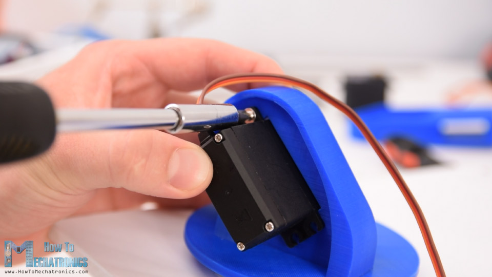
The first servo of the robot arm will be directly mounted on the top cover of the mecanum wheels platform.
I marked the location, and using a 10mm drill I made several holes.
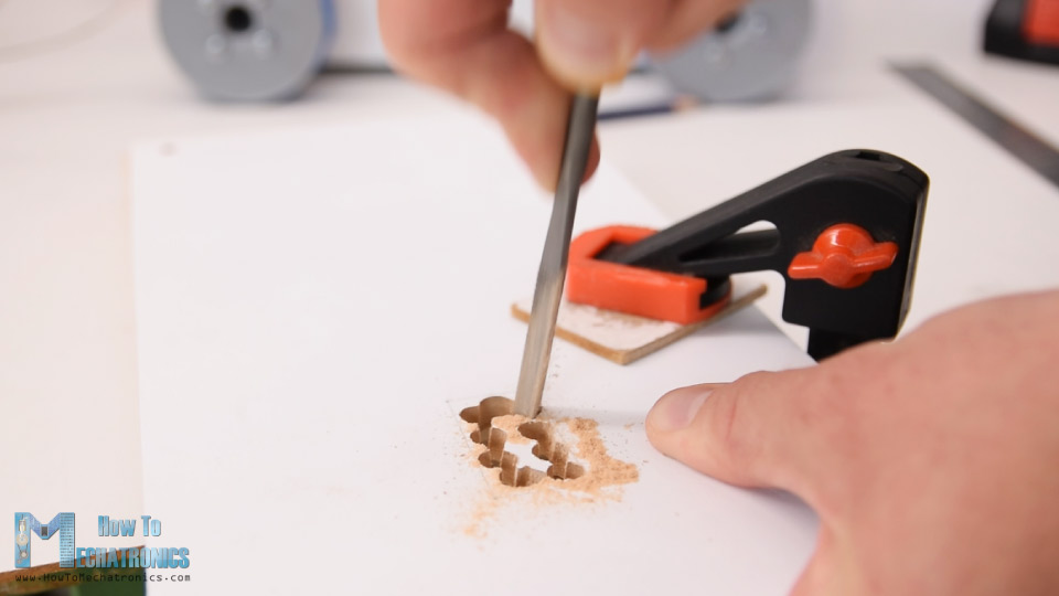
Then using a rasp, I cut through the holes and then fine-tuned the opening for the servo. I secured the servo to the top plate using four M3 bolts and nuts.
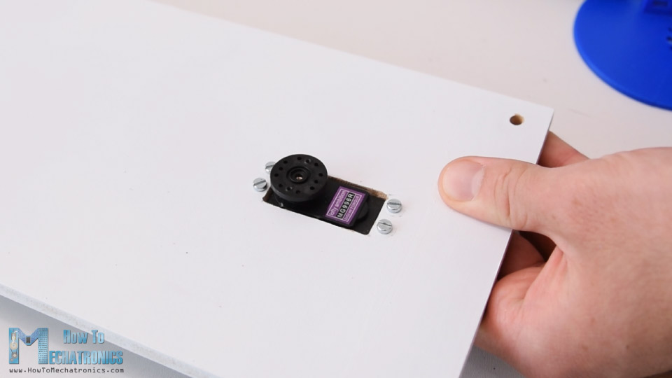
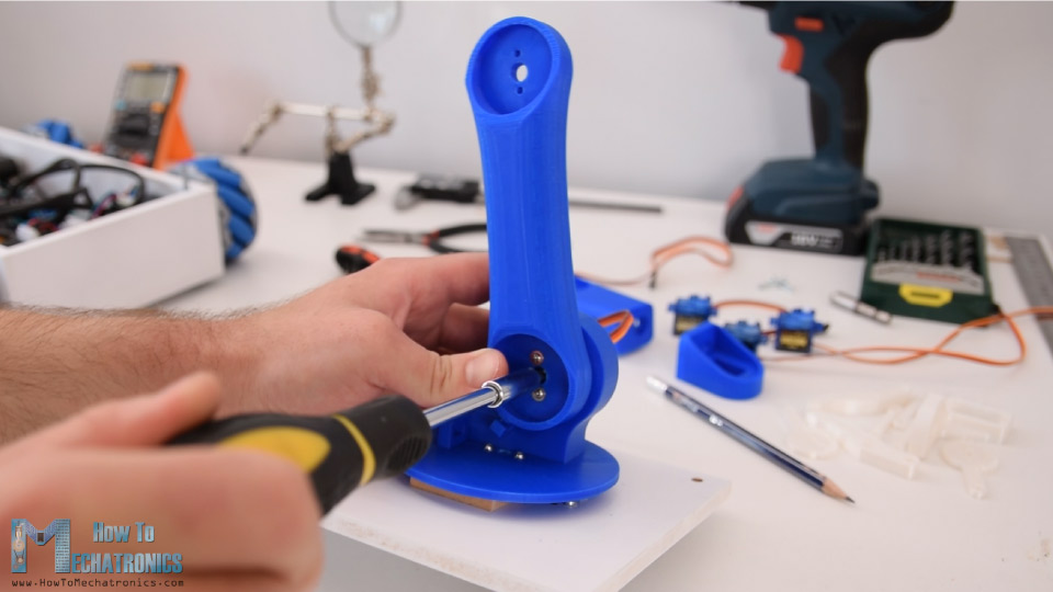
Then on this output shaft of this servo, using the round horn that comes as accessory with the servo, we need to attach the next part or the waist of the robot arm. However, we can notice that in this way the part stays around 8mm above the plate. So therefore, I attached two pieces of 8mm MDF boards, so the waist part can slide on them and so the joint will be more stable.
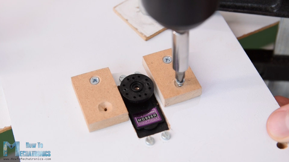
The round horn is secured to the waist part using the self-tapping screws that come as accessories with the servo, and then the round horn is secured to servo shaft using the appropriate bolts that also come with the servo.
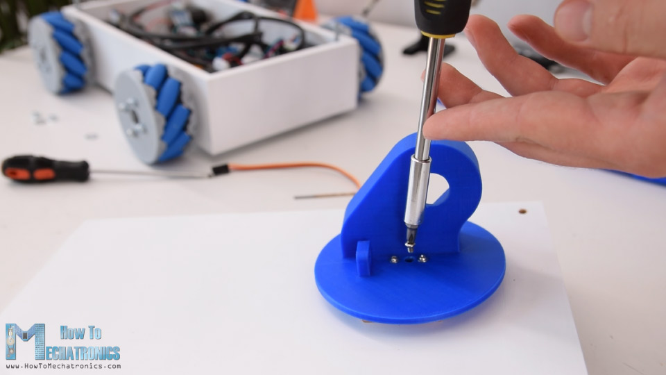
Next we have the shoulder servo. We simply put it in place and secure it to the 3D printed part using self-tapping screws.
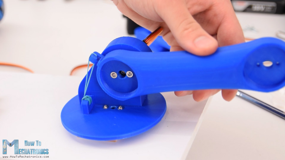
The round horn goes on the next part, and then the two parts are secured to each other using a bolt on the output shaft of the servo.
We should note that before securing the parts, we need to make sure that the part has the full range of motion. Here I also added a rubber band to the shoulder joint so that it gives a little bit help to the servo, because this servo carries the weight of the rest of the arm as well as the payload.
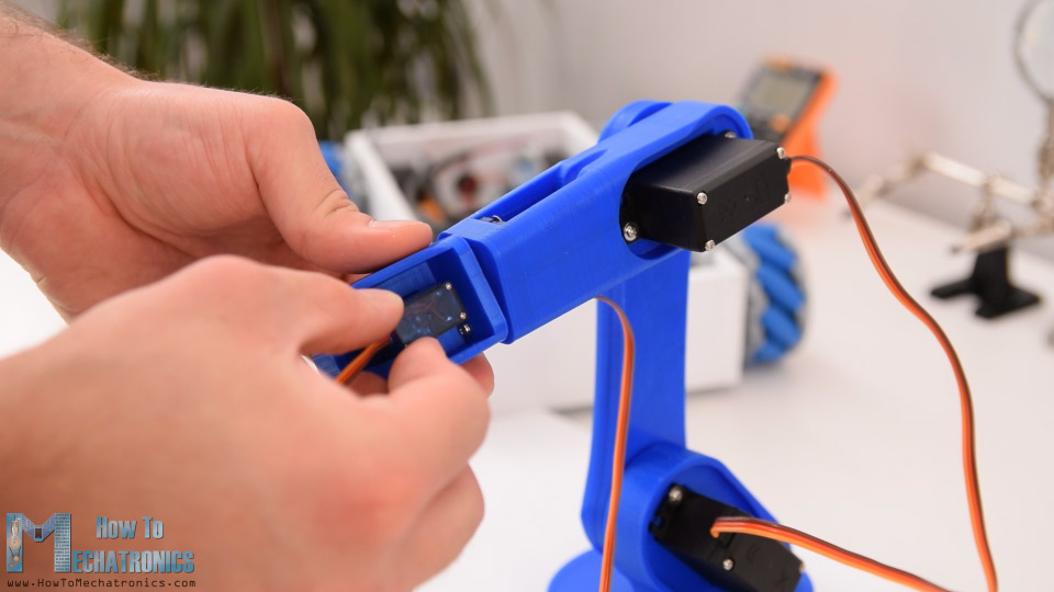
In similar way, I assembled the rest of the robot arm.
Next, we need to assemble to gripper mechanism. The gripper is controlled with an SG90 servo motor, on which, first we attach a custom designed geared link. We pair this link with another geared link on the other side, which is secured using M4 bolt and nuts. Actually, all other links are connected using M4 bolts and nuts.
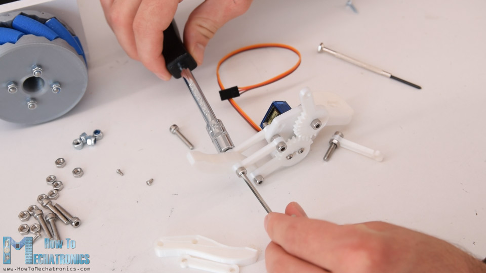
The 3D model of the gripper originally has 3mm holes but I didn’t have enough M3 bolts, so therefore I expanded the holes using 4mm drill and used the M4 bolts instead.
Once I assembled the gripper mechanism, I secured it to the last servo and so the robot arm was completed.
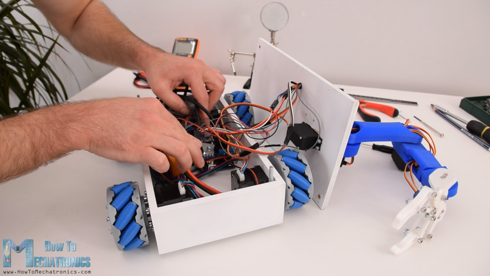
Next I did some cable management. I passed the servo wires through the specifically designed holes of the robot arm. Using a 10mm drill I made a hole on the top plate so that the wires can pass through.
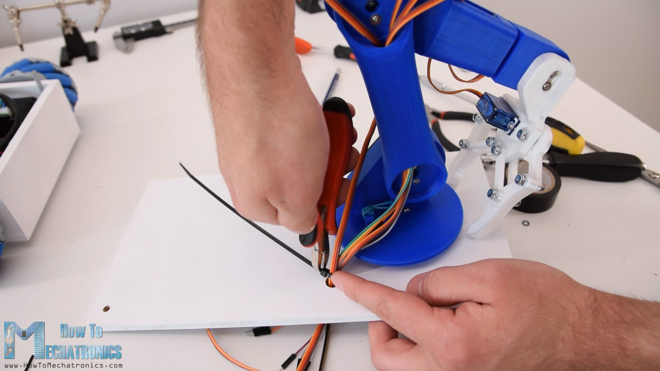
Using a zip-tie I secured all the wires together, and now what’s left is to connect them to the Arduino board.
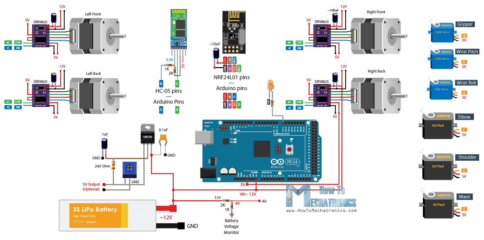
Arduino Robot Circuit Diagram
Here’s the circuit diagram of this project and how everything needs to be connected.
You can get the components needed for this project from the links below:
- Stepper Motor – NEMA 17 …………..… Amazon / Banggood / AliExpress
- DRV8825 Stepper Driver ……….…….… Amazon / Banggood / AliExpress
- MG996R Servo Motor………………….…. Amazon / Banggood / AliExpress
- SG90 Micro Servo Motor …………….…. Amazon / Banggood / AliExpress
- HC-05 Bluetooth Module …………….… Amazon / Banggood / AliExpress
- Li-Po battery …………………………….…… Amazon / Banggood / AliExpress
- Arduino Mega Board ………….……….… Amazon / Banggood / AliExpress
Disclosure: These are affiliate links. As an Amazon Associate I earn from qualifying purchases.
In the previous tutorial I explained how the Mecanum wheels robot part works and also showed you how I made a custom PCB for it.
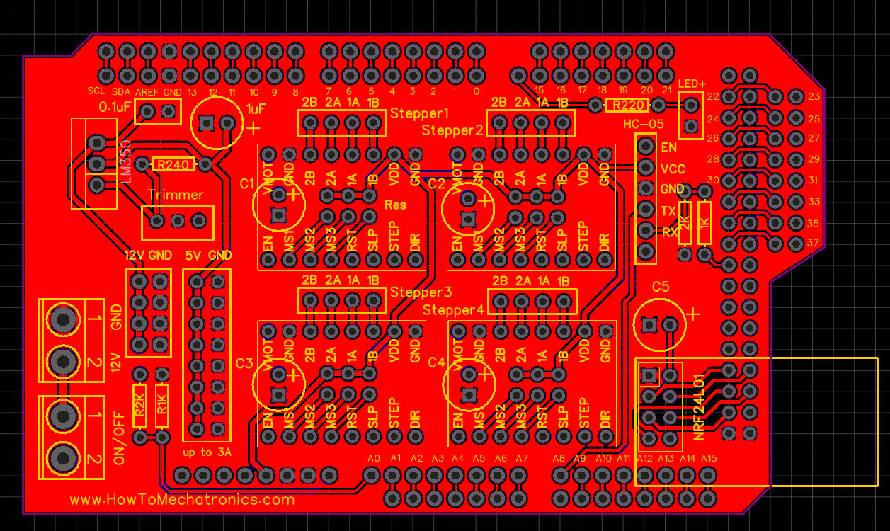
I included a 5V voltage regulator on this PCB so that we can make this project, or connect the servo motors because they work at 5V. The voltage regulator is the LM350, which can handle up to 3 amps of current. All six servos of the robot arm can draw from around 2 amps to 3 amps of current, which means that it can handle them but that will cause the regulator to get very hot.
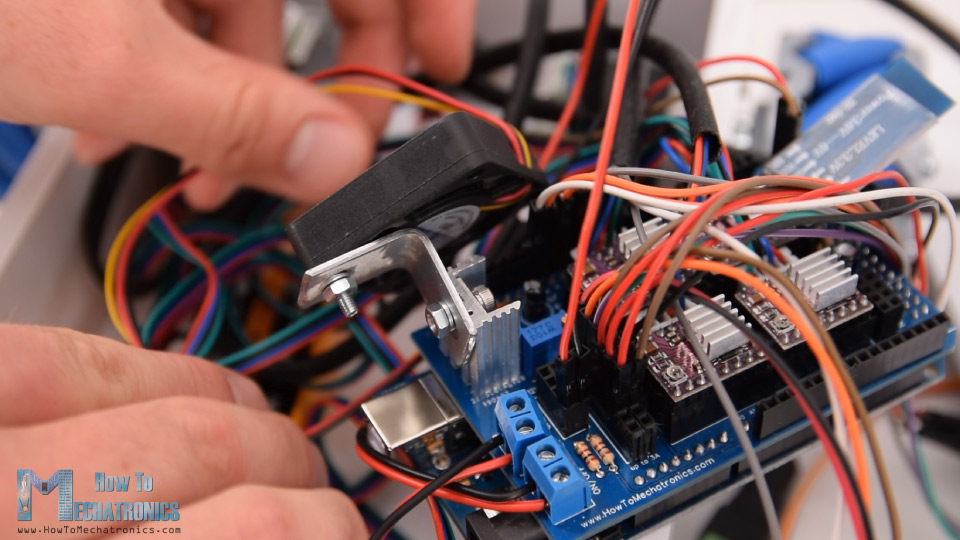
Therefore, I attached a heat sink to it, as well as a small 12V DC fan to blow some air, because the heat sink itself wasn’t enough the cool the regulator.
I connected the servos signal wires to the Arduino digital pins from number 5 to 10, and for powering I used the 5V pin header on the PCB. Finally, I pushed all the wires inside the platform, and secured the top plate to it using the two nuts.
And that’s it, now we are done with this project.
Arduino Code
What’s left is to take a look how the Arduino code and the Android application work. As the code is a bit longer, for better understanding, I will post the source code of the program in sections with description for each section. And at the end of this article I will post the complete source code.
So first we need to define the 6 servo, the 4 stepper motors and the Bluetooth communication, as well as define some variables need for the program below. In the setup section we set the maximum speed of the steppers, define the pins to which the servos are connected, begin the Bluetooth communication and set the robot arm to initial position.
#include <SoftwareSerial.h>
#include <AccelStepper.h>
#include <Servo.h>

Servo servo01;
Servo servo02;
Servo servo03;
Servo servo04;
Servo servo05;
Servo servo06;

SoftwareSerial Bluetooth(A8, 38); // Arduino(RX, TX) - HC-05 Bluetooth (TX, RX)

// Define the stepper motors and the pins the will use
AccelStepper LeftBackWheel(1, 42, 43);   // (Type:driver, STEP, DIR) - Stepper1
AccelStepper LeftFrontWheel(1, 40, 41);  // Stepper2
AccelStepper RightBackWheel(1, 44, 45);  // Stepper3
AccelStepper RightFrontWheel(1, 46, 47); // Stepper4

#define led 14

int wheelSpeed = 1500;

int lbw[50], lfw[50], rbw[50], rfw[50]; // arrays for storing positions/steps

int servo1Pos, servo2Pos, servo3Pos, servo4Pos, servo5Pos, servo6Pos; // current position
int servo1PPos, servo2PPos, servo3PPos, servo4PPos, servo5PPos, servo6PPos; // previous position
int servo01SP[50], servo02SP[50], servo03SP[50], servo04SP[50], servo05SP[50], servo06SP[50]; // for storing positions/steps
int speedDelay = 20;
int index = 0;
int dataIn;
int m = 0;

void setup() {
  // Set initial seed values for the steppers
  LeftFrontWheel.setMaxSpeed(3000);
  LeftBackWheel.setMaxSpeed(3000);
  RightFrontWheel.setMaxSpeed(3000);
  RightBackWheel.setMaxSpeed(3000);
  pinMode(led, OUTPUT);
  servo01.attach(5);
  servo02.attach(6);
  servo03.attach(7);
  servo04.attach(8);
  servo05.attach(9);
  servo06.attach(10);
  Bluetooth.begin(38400); // Default baud rate of the Bluetooth module
  Bluetooth.setTimeout(5);
  delay(20);
  Serial.begin(38400);
  // Move robot arm to initial position
  servo1PPos = 90;
  servo01.write(servo1PPos);
  servo2PPos = 100;
  servo02.write(servo2PPos);
  servo3PPos = 120;
  servo03.write(servo3PPos);
  servo4PPos = 95;
  servo04.write(servo4PPos);
  servo5PPos = 60;
  servo05.write(servo5PPos);
  servo6PPos = 110;
  servo06.write(servo6PPos);
}Code language: PHP (php)
Then in the loop section we start by checking whether there is any incoming data.
// Check for incoming data
  if (Bluetooth.available() > 0) {
    dataIn = Bluetooth.read();  // Read the dataCode language: JavaScript (javascript)
This data comes from the smartphone or the Android app, so let’s take a look what kind of data it is actually sending. The Android app is made using the MIT App Inventor online application. It consists of simple buttons which have appropriate images as background.
If we take a look at the blocks of the app, we can see that all it does is it sends one-byte numbers when the buttons are clicked.
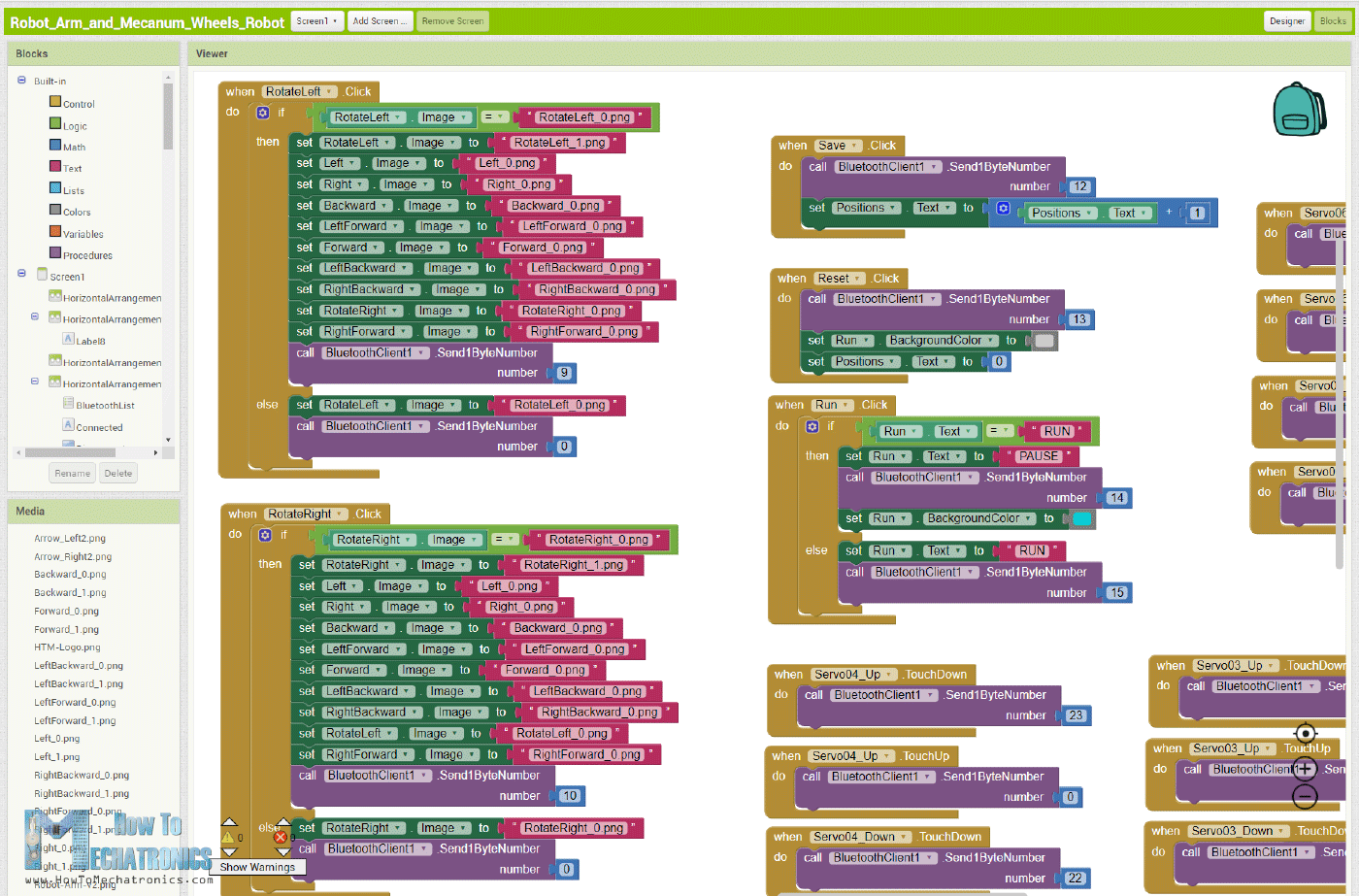
So, depending on clicked button, we tell the Arduino what to do. For example, if we receive the number ‘2’ the mecanum wheels platform will move forward, using the moveForward custom function.
if (dataIn == 2) {
      m = 2;
    }
//
if (m == 2) {
      moveForward();
    }Code language: JavaScript (javascript)
This custom function sets all four stepper motors to rotate forward.
void moveForward() {
  LeftFrontWheel.setSpeed(wheelSpeed);
  LeftBackWheel.setSpeed(wheelSpeed);
  RightFrontWheel.setSpeed(wheelSpeed);
  RightBackWheel.setSpeed(wheelSpeed);
}Code language: JavaScript (javascript)
For moving in any other direction, we just need rotate the wheels in the appropriate directions.
For controlling the robot arm, we use the same method. Again, we have buttons in the app and when holding the buttons, the robot arm joints move in the particular direction.
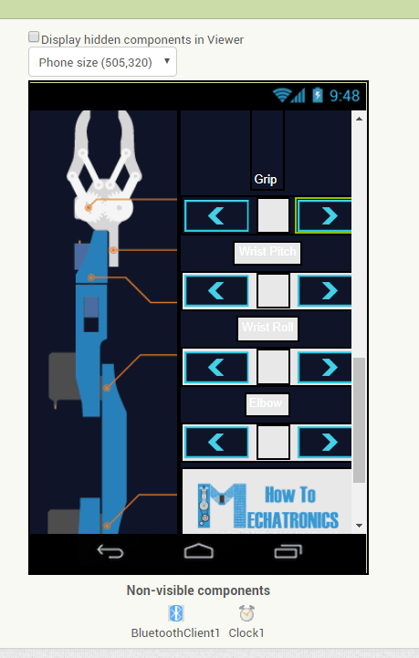
As I mentioned earlier, in the original Robot Arm control app we were using sliders for controlling the positions of the servos but that was causing some problems because in that way we had to send Text to the Arduino, instead of 1-byte number. The problem is the Arduino sometimes misses the Text coming from the App and makes error or the Robot arm shakes and behaves abnormal.
In this way we simple send a single 1-byte number when a particular button is touched down.
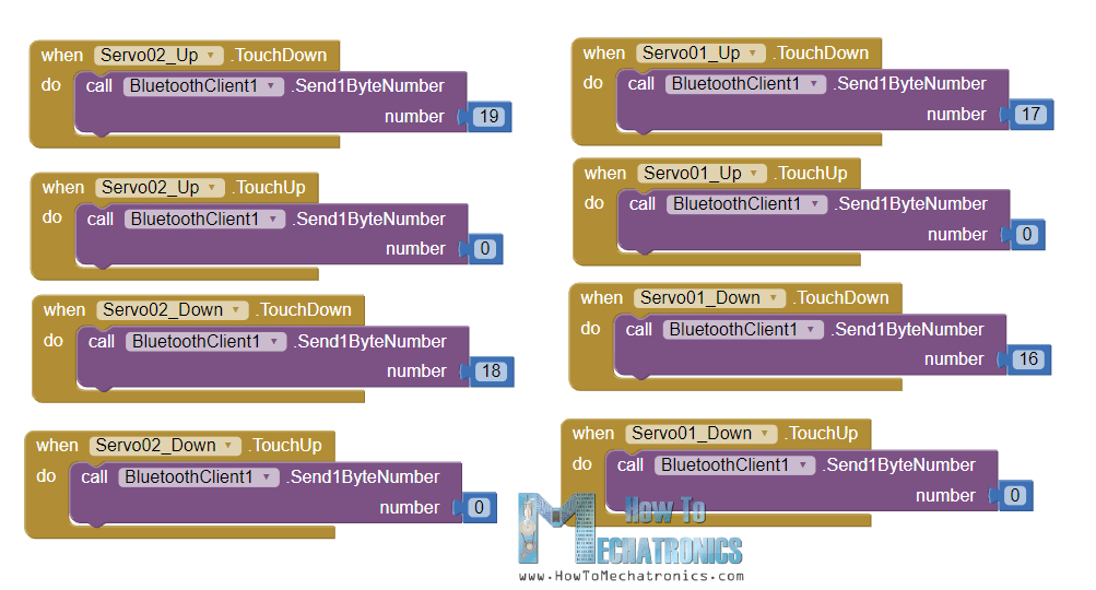
The Arduino code enters the while loop of that number, and stays there until we touch up the button, because at that moment we send the number 0 which means the robot should do nothing.
// Move servo 1 in positive direction
    while (m == 16) {
      if (Bluetooth.available() > 0) {
        m = Bluetooth.read();
      }
      servo01.write(servo1PPos);
      servo1PPos++;
      delay(speedDelay);
    }
    // Move servo 1 in negative direction
    while (m == 17) {
      if (Bluetooth.available() > 0) {
        m = Bluetooth.read();
      }
      servo01.write(servo1PPos);
      servo1PPos--;
      delay(speedDelay);
    }Code language: JavaScript (javascript)
So, depending on the touched buttons the servos move either in positive or negative direction. The same working principle applies for all servo motors. For changing the speed of movement, we use the values coming from the slider which range from 100 to 250.
// If arm speed slider is changed
    if (dataIn > 101 & dataIn < 250) {
      speedDelay = dataIn / 10; // Change servo speed (delay time)
    }Code language: JavaScript (javascript)
By dividing them by 10 we get values from 10 to 25, which are used as delay in microseconds in the whiles loops for driving the servos.
For storing the robot movements, we simply save the current positions of the servos and the steppers into arrays, each time the Save button is clicked.
// If button "SAVE" is pressed
    if (m == 12) {
      //if it's initial save, set the steppers position to 0
      if (index == 0) {
        LeftBackWheel.setCurrentPosition(0);
        LeftFrontWheel.setCurrentPosition(0);
        RightBackWheel.setCurrentPosition(0);
        RightFrontWheel.setCurrentPosition(0);
      }
      lbw[index] = LeftBackWheel.currentPosition();  // save position into the array
      lfw[index] = LeftFrontWheel.currentPosition();
      rbw[index] = RightBackWheel.currentPosition();
      rfw[index] = RightFrontWheel.currentPosition();

      servo01SP[index] = servo1PPos;  // save position into the array
      servo02SP[index] = servo2PPos;
      servo03SP[index] = servo3PPos;
      servo04SP[index] = servo4PPos;
      servo05SP[index] = servo5PPos;
      servo06SP[index] = servo6PPos;
      index++;                        // Increase the array index
      m = 0;
    }Code language: JavaScript (javascript)
Then when we press the Run button we call the runSteps() custom function. This custom function runs through all stored steps using some for and while loops.
if (m == 14) {
      runSteps();

      // If button "RESET" is pressed
      if (dataIn != 14) {
        stopMoving();
        memset(lbw, 0, sizeof(lbw)); // Clear the array data to 0
        memset(lfw, 0, sizeof(lfw));
        memset(rbw, 0, sizeof(rbw));
        memset(rfw, 0, sizeof(rfw));
        memset(servo01SP, 0, sizeof(servo01SP)); // Clear the array data to 0
        memset(servo02SP, 0, sizeof(servo02SP));
        memset(servo03SP, 0, sizeof(servo03SP));
        memset(servo04SP, 0, sizeof(servo04SP));
        memset(servo05SP, 0, sizeof(servo05SP));
        memset(servo06SP, 0, sizeof(servo06SP));
        index = 0;  // Index to 0
      }
    }Code language: JavaScript (javascript)
We should note that it starts from the first position and goes the last position, and repeats that over and over again. Therefore, when saving the steps, we actually need to position the robot in a way that the first step has the same position as the last step. While running through the steps we can also change the speed of both the platform and the robot arm, as well as pause and reset all the steps.
Here you can download this app as well as the editable project file:
Here’s the complete Arduino code for this Arduino robot project:
/*
       Arduino Robot Arm and Mecanum Wheels Robot
          Smartphone Control via Bluetooth
       by Dejan, www.HowToMechatronics.com
*/

#include <SoftwareSerial.h>
#include <AccelStepper.h>
#include <Servo.h>

Servo servo01;
Servo servo02;
Servo servo03;
Servo servo04;
Servo servo05;
Servo servo06;

SoftwareSerial Bluetooth(A8, 38); // Arduino(RX, TX) - HC-05 Bluetooth (TX, RX)

// Define the stepper motors and the pins the will use
AccelStepper LeftBackWheel(1, 42, 43);   // (Type:driver, STEP, DIR) - Stepper1
AccelStepper LeftFrontWheel(1, 40, 41);  // Stepper2
AccelStepper RightBackWheel(1, 44, 45);  // Stepper3
AccelStepper RightFrontWheel(1, 46, 47); // Stepper4

#define led 14

int wheelSpeed = 1500;

int lbw[50], lfw[50], rbw[50], rfw[50]; // arrays for storing positions/steps

int servo1Pos, servo2Pos, servo3Pos, servo4Pos, servo5Pos, servo6Pos; // current position
int servo1PPos, servo2PPos, servo3PPos, servo4PPos, servo5PPos, servo6PPos; // previous position
int servo01SP[50], servo02SP[50], servo03SP[50], servo04SP[50], servo05SP[50], servo06SP[50]; // for storing positions/steps
int speedDelay = 20;
int index = 0;
int dataIn;
int m = 0;

void setup() {
  // Set initial seed values for the steppers
  LeftFrontWheel.setMaxSpeed(3000);
  LeftBackWheel.setMaxSpeed(3000);
  RightFrontWheel.setMaxSpeed(3000);
  RightBackWheel.setMaxSpeed(3000);
  pinMode(led, OUTPUT);
  servo01.attach(5);
  servo02.attach(6);
  servo03.attach(7);
  servo04.attach(8);
  servo05.attach(9);
  servo06.attach(10);
  Bluetooth.begin(38400); // Default baud rate of the Bluetooth module
  Bluetooth.setTimeout(5);
  delay(20);
  Serial.begin(38400);
  // Move robot arm to initial position
  servo1PPos = 90;
  servo01.write(servo1PPos);
  servo2PPos = 100;
  servo02.write(servo2PPos);
  servo3PPos = 120;
  servo03.write(servo3PPos);
  servo4PPos = 95;
  servo04.write(servo4PPos);
  servo5PPos = 60;
  servo05.write(servo5PPos);
  servo6PPos = 110;
  servo06.write(servo6PPos);
}

void loop() {
  // Check for incoming data
  if (Bluetooth.available() > 0) {
    dataIn = Bluetooth.read();  // Read the data

    if (dataIn == 0) {
      m = 0;
    }
    if (dataIn == 1) {
      m = 1;
    }
    if (dataIn == 2) {
      m = 2;
    }
    if (dataIn == 3) {
      m = 3;
    }
    if (dataIn == 4) {
      m = 4;
    }
    if (dataIn == 5) {
      m = 5;
    }
    if (dataIn == 6) {
      m = 6;
    }
    if (dataIn == 7) {
      m = 7;
    }
    if (dataIn == 8) {
      m = 8;
    }
    if (dataIn == 9) {
      m = 9;
    }
    if (dataIn == 10) {
      m = 10;
    }
    if (dataIn == 11) {
      m = 11;
    }
    if (dataIn == 12) {
      m = 12;
    }
    if (dataIn == 14) {
      m = 14;
    }
    if (dataIn == 16) {
      m = 16;
    }
    if (dataIn == 17) {
      m = 17;
    }
    if (dataIn == 18) {
      m = 18;
    }
    if (dataIn == 19) {
      m = 19;
    }
    if (dataIn == 20) {
      m = 20;
    }
    if (dataIn == 21) {
      m = 21;
    }
    if (dataIn == 22) {
      m = 22;
    }
    if (dataIn == 23) {
      m = 23;
    }
    if (dataIn == 24) {
      m = 24;
    }
    if (dataIn == 25) {
      m = 25;
    }
    if (dataIn == 26) {
      m = 26;
    }
    if (dataIn == 27) {
      m = 27;
    }

    // Move the Mecanum wheels platform
    if (m == 4) {
      moveSidewaysLeft();
    }
    if (m == 5) {
      moveSidewaysRight();
    }
    if (m == 2) {
      moveForward();
    }
    if (m == 7) {
      moveBackward();
    }
    if (m == 3) {
      moveRightForward();
    }
    if (m == 1) {
      moveLeftForward();
    }
    if (m == 8) {
      moveRightBackward();
    }
    if (m == 6) {
      moveLeftBackward();
    }
    if (m == 9) {
      rotateLeft();
    }
    if (m == 10) {
      rotateRight();
    }

    if (m == 0) {
      stopMoving();
    }

    // Mecanum wheels speed
    if (dataIn > 30 & dataIn < 100) {
      wheelSpeed = dataIn * 20;
    }

    // Move robot arm
    // Move servo 1 in positive direction
    while (m == 16) {
      if (Bluetooth.available() > 0) {
        m = Bluetooth.read();
      }
      servo01.write(servo1PPos);
      servo1PPos++;
      delay(speedDelay);
    }
    // Move servo 1 in negative direction
    while (m == 17) {
      if (Bluetooth.available() > 0) {
        m = Bluetooth.read();
      }
      servo01.write(servo1PPos);
      servo1PPos--;
      delay(speedDelay);
    }
    // Move servo 2
    while (m == 19) {
      if (Bluetooth.available() > 0) {
        m = Bluetooth.read();
      }
      servo02.write(servo2PPos);
      servo2PPos++;
      delay(speedDelay);
    }
    while (m == 18) {
      if (Bluetooth.available() > 0) {
        m = Bluetooth.read();
      }
      servo02.write(servo2PPos);
      servo2PPos--;
      delay(speedDelay);
    }
    // Move servo 3
    while (m == 20) {
      if (Bluetooth.available() > 0) {
        m = Bluetooth.read();
      }
      servo03.write(servo3PPos);
      servo3PPos++;
      delay(speedDelay);
    }
    while (m == 21) {
      if (Bluetooth.available() > 0) {
        m = Bluetooth.read();
      }
      servo03.write(servo3PPos);
      servo3PPos--;
      delay(speedDelay);
    }
    // Move servo 4
    while (m == 23) {
      if (Bluetooth.available() > 0) {
        m = Bluetooth.read();
      }
      servo04.write(servo4PPos);
      servo4PPos++;
      delay(speedDelay);
    }
    while (m == 22) {
      if (Bluetooth.available() > 0) {
        m = Bluetooth.read();
      }
      servo04.write(servo4PPos);
      servo4PPos--;
      delay(speedDelay);
    }
    // Move servo 5
    while (m == 25) {
      if (Bluetooth.available() > 0) {
        m = Bluetooth.read();
      }
      servo05.write(servo5PPos);
      servo5PPos++;
      delay(speedDelay);
    }
    while (m == 24) {
      if (Bluetooth.available() > 0) {
        m = Bluetooth.read();
      }
      servo05.write(servo5PPos);
      servo5PPos--;
      delay(speedDelay);
    }
    // Move servo 6
    while (m == 26) {
      if (Bluetooth.available() > 0) {
        m = Bluetooth.read();
      }
      servo06.write(servo6PPos);
      servo6PPos++;
      delay(speedDelay);
    }
    while (m == 27) {
      if (Bluetooth.available() > 0) {
        m = Bluetooth.read();
      }
      servo06.write(servo6PPos);
      servo6PPos--;
      delay(speedDelay);
    }

    // If arm speed slider is changed
    if (dataIn > 101 & dataIn < 250) {
      speedDelay = dataIn / 10; // Change servo speed (delay time)
    }

    // If button "SAVE" is pressed
    if (m == 12) {
      //if it's initial save, set the steppers position to 0
      if (index == 0) {
        LeftBackWheel.setCurrentPosition(0);
        LeftFrontWheel.setCurrentPosition(0);
        RightBackWheel.setCurrentPosition(0);
        RightFrontWheel.setCurrentPosition(0);
      }
      lbw[index] = LeftBackWheel.currentPosition();  // save position into the array
      lfw[index] = LeftFrontWheel.currentPosition();
      rbw[index] = RightBackWheel.currentPosition();
      rfw[index] = RightFrontWheel.currentPosition();

      servo01SP[index] = servo1PPos;  // save position into the array
      servo02SP[index] = servo2PPos;
      servo03SP[index] = servo3PPos;
      servo04SP[index] = servo4PPos;
      servo05SP[index] = servo5PPos;
      servo06SP[index] = servo6PPos;
      index++;                        // Increase the array index
      m = 0;
    }

    // If button "RUN" is pressed
    if (m == 14) {
      runSteps();

      // If button "RESET" is pressed
      if (dataIn != 14) {
        stopMoving();
        memset(lbw, 0, sizeof(lbw)); // Clear the array data to 0
        memset(lfw, 0, sizeof(lfw));
        memset(rbw, 0, sizeof(rbw));
        memset(rfw, 0, sizeof(rfw));
        memset(servo01SP, 0, sizeof(servo01SP)); // Clear the array data to 0
        memset(servo02SP, 0, sizeof(servo02SP));
        memset(servo03SP, 0, sizeof(servo03SP));
        memset(servo04SP, 0, sizeof(servo04SP));
        memset(servo05SP, 0, sizeof(servo05SP));
        memset(servo06SP, 0, sizeof(servo06SP));
        index = 0;  // Index to 0
      }
    }
  }
  LeftFrontWheel.runSpeed();
  LeftBackWheel.runSpeed();
  RightFrontWheel.runSpeed();
  RightBackWheel.runSpeed();

  // Monitor the battery voltage
  int sensorValue = analogRead(A0);
  float voltage = sensorValue * (5.0 / 1023.00) * 3; // Convert the reading values from 5v to suitable 12V i
  //Serial.println(voltage);
  // If voltage is below 11V turn on the LED
  if (voltage < 11) {
    digitalWrite(led, HIGH);
  }
  else {
    digitalWrite(led, LOW);
  }
}
void moveForward() {
  LeftFrontWheel.setSpeed(wheelSpeed);
  LeftBackWheel.setSpeed(wheelSpeed);
  RightFrontWheel.setSpeed(wheelSpeed);
  RightBackWheel.setSpeed(wheelSpeed);
}
void moveBackward() {
  LeftFrontWheel.setSpeed(-wheelSpeed);
  LeftBackWheel.setSpeed(-wheelSpeed);
  RightFrontWheel.setSpeed(-wheelSpeed);
  RightBackWheel.setSpeed(-wheelSpeed);
}
void moveSidewaysRight() {
  LeftFrontWheel.setSpeed(wheelSpeed);
  LeftBackWheel.setSpeed(-wheelSpeed);
  RightFrontWheel.setSpeed(-wheelSpeed);
  RightBackWheel.setSpeed(wheelSpeed);
}
void moveSidewaysLeft() {
  LeftFrontWheel.setSpeed(-wheelSpeed);
  LeftBackWheel.setSpeed(wheelSpeed);
  RightFrontWheel.setSpeed(wheelSpeed);
  RightBackWheel.setSpeed(-wheelSpeed);
}
void rotateLeft() {
  LeftFrontWheel.setSpeed(-wheelSpeed);
  LeftBackWheel.setSpeed(-wheelSpeed);
  RightFrontWheel.setSpeed(wheelSpeed);
  RightBackWheel.setSpeed(wheelSpeed);
}
void rotateRight() {
  LeftFrontWheel.setSpeed(wheelSpeed);
  LeftBackWheel.setSpeed(wheelSpeed);
  RightFrontWheel.setSpeed(-wheelSpeed);
  RightBackWheel.setSpeed(-wheelSpeed);
}
void moveRightForward() {
  LeftFrontWheel.setSpeed(wheelSpeed);
  LeftBackWheel.setSpeed(0);
  RightFrontWheel.setSpeed(0);
  RightBackWheel.setSpeed(wheelSpeed);
}
void moveRightBackward() {
  LeftFrontWheel.setSpeed(0);
  LeftBackWheel.setSpeed(-wheelSpeed);
  RightFrontWheel.setSpeed(-wheelSpeed);
  RightBackWheel.setSpeed(0);
}
void moveLeftForward() {
  LeftFrontWheel.setSpeed(0);
  LeftBackWheel.setSpeed(wheelSpeed);
  RightFrontWheel.setSpeed(wheelSpeed);
  RightBackWheel.setSpeed(0);
}
void moveLeftBackward() {
  LeftFrontWheel.setSpeed(-wheelSpeed);
  LeftBackWheel.setSpeed(0);
  RightFrontWheel.setSpeed(0);
  RightBackWheel.setSpeed(-wheelSpeed);
}
void stopMoving() {
  LeftFrontWheel.setSpeed(0);
  LeftBackWheel.setSpeed(0);
  RightFrontWheel.setSpeed(0);
  RightBackWheel.setSpeed(0);
}

// Automatic mode custom function - run the saved steps
void runSteps() {
  while (dataIn != 13) {   // Run the steps over and over again until "RESET" button is pressed
    for (int i = 0; i <= index - 2; i++) {  // Run through all steps(index)
      if (Bluetooth.available() > 0) {      // Check for incomding data
        dataIn = Bluetooth.read();
        if ( dataIn == 15) {           // If button "PAUSE" is pressed
          while (dataIn != 14) {         // Wait until "RUN" is pressed again
            if (Bluetooth.available() > 0) {
              dataIn = Bluetooth.read();
              if ( dataIn == 13) {
                break;
              }
            }
          }
        }
        // If speed slider is changed
        if (dataIn > 100 & dataIn < 150) {
          speedDelay = dataIn / 10; // Change servo speed (delay time)
        }
        // Mecanum wheels speed
        if (dataIn > 30 & dataIn < 100) {
          wheelSpeed = dataIn * 10;
          dataIn = 14;
        }
      }
      LeftFrontWheel.moveTo(lfw[i]);
      LeftFrontWheel.setSpeed(wheelSpeed);
      LeftBackWheel.moveTo(lbw[i]);
      LeftBackWheel.setSpeed(wheelSpeed);
      RightFrontWheel.moveTo(rfw[i]);
      RightFrontWheel.setSpeed(wheelSpeed);
      RightBackWheel.moveTo(rbw[i]);
      RightBackWheel.setSpeed(wheelSpeed);

      while (LeftBackWheel.currentPosition() != lbw[i] & LeftFrontWheel.currentPosition() != lfw[i] & RightFrontWheel.currentPosition() != rfw[i] & RightBackWheel.currentPosition() != rbw[i]) {
        LeftFrontWheel.runSpeedToPosition();
        LeftBackWheel.runSpeedToPosition();
        RightFrontWheel.runSpeedToPosition();
        RightBackWheel.runSpeedToPosition();
      }
      // Servo 1
      if (servo01SP[i] == servo01SP[i + 1]) {
      }
      if (servo01SP[i] > servo01SP[i + 1]) {
        for ( int j = servo01SP[i]; j >= servo01SP[i + 1]; j--) {
          servo01.write(j);
          delay(speedDelay);
        }
      }
      if (servo01SP[i] < servo01SP[i + 1]) {
        for ( int j = servo01SP[i]; j <= servo01SP[i + 1]; j++) {
          servo01.write(j);
          delay(speedDelay);
        }
      }

      // Servo 2
      if (servo02SP[i] == servo02SP[i + 1]) {
      }
      if (servo02SP[i] > servo02SP[i + 1]) {
        for ( int j = servo02SP[i]; j >= servo02SP[i + 1]; j--) {
          servo02.write(j);
          delay(speedDelay);
        }
      }
      if (servo02SP[i] < servo02SP[i + 1]) {
        for ( int j = servo02SP[i]; j <= servo02SP[i + 1]; j++) {
          servo02.write(j);
          delay(speedDelay);
        }
      }

      // Servo 3
      if (servo03SP[i] == servo03SP[i + 1]) {
      }
      if (servo03SP[i] > servo03SP[i + 1]) {
        for ( int j = servo03SP[i]; j >= servo03SP[i + 1]; j--) {
          servo03.write(j);
          delay(speedDelay);
        }
      }
      if (servo03SP[i] < servo03SP[i + 1]) {
        for ( int j = servo03SP[i]; j <= servo03SP[i + 1]; j++) {
          servo03.write(j);
          delay(speedDelay);
        }
      }

      // Servo 4
      if (servo04SP[i] == servo04SP[i + 1]) {
      }
      if (servo04SP[i] > servo04SP[i + 1]) {
        for ( int j = servo04SP[i]; j >= servo04SP[i + 1]; j--) {
          servo04.write(j);
          delay(speedDelay);
        }
      }
      if (servo04SP[i] < servo04SP[i + 1]) {
        for ( int j = servo04SP[i]; j <= servo04SP[i + 1]; j++) {
          servo04.write(j);
          delay(speedDelay);
        }
      }

      // Servo 5
      if (servo05SP[i] == servo05SP[i + 1]) {
      }
      if (servo05SP[i] > servo05SP[i + 1]) {
        for ( int j = servo05SP[i]; j >= servo05SP[i + 1]; j--) {
          servo05.write(j);
          delay(speedDelay);
        }
      }
      if (servo05SP[i] < servo05SP[i + 1]) {
        for ( int j = servo05SP[i]; j <= servo05SP[i + 1]; j++) {
          servo05.write(j);
          delay(speedDelay);
        }
      }

      // Servo 6
      if (servo06SP[i] == servo06SP[i + 1]) {
      }
      if (servo06SP[i] > servo06SP[i + 1]) {
        for ( int j = servo06SP[i]; j >= servo06SP[i + 1]; j--) {
          servo06.write(j);
          delay(speedDelay);
        }
      }
      if (servo06SP[i] < servo06SP[i + 1]) {
        for ( int j = servo06SP[i]; j <= servo06SP[i + 1]; j++) {
          servo06.write(j);
          delay(speedDelay);
        }
      }
    }
  }
}Code language: PHP (php)
So that’s pretty much everything for this tutorial. The project works well, but please note that it’s far from perfect. The automatic movements might not be that precise because of the slipping of the mecanum wheels as well as the poor performance of the servo motors. These cheap servo motors can also shake or jitter even when not moving just because don’t have enough strength to hold the weight of the 3D printed parts.
I hope you enjoyed this tutorial and learned something new. Feel free to ask any question in the comments section below and check my Arduino Projects Collection.
Hi Dejan,
Can you please upload the file for application which has both code for robotic arm as well as wheel
I have downloaded Arduino Robot Arm and Mecanum Wheels Robot App Files above but it seems to have only the wheel
Thank you so much!
Please try again, I’ve just updated the file. Clear your browser cache first though. Cheers!
hi
loved your projects
A special thanks to you.
Subscribed!!
Hi ..nice project.i tried building it with ur materials
Buh my servo isn’t moving at all
Checked the date received by the Bluetooth using the serial monitor n also tried printing in the function responsible for moving the servo n the code n app interaction seem just fine
Buh the servo wouldn’t move even after try an external 5v powe source
Hi, thanks!
Well it’s hard to tell what could be the problem. What about other functions, does the stepper motors works? Try to move the servos with some simple code just to check whether the connections are fine.
Dear Dejan,
I made this for my final high school project and was selected as one of the top 10.
I am really thankful for your tutorial both the video and the article as that are really easy to follow.
Well there’s more I wanted to say but I can’t really make it into words as I’m not a native English speaker. Thanks for your youtube video and this website!
Wise
Hey, so glad to hear it!
Hey, I need Arduino Robotic Arm and Mecanum Wheels 3D Model – SOLIDWORKS Files Include all parts and assembly of Robotic Arm and Mecanum Wheels. I tried download Arduino Robotic Arm and Mecanum Wheels Platfrom 3D Model STEP File but this not valid and nor zipped file ..
Briefly, I need a 3D model (SLDPRT files)
Hello Dejan,
My son and I really love this project, we are working on it together and that creates an excellent bond between us.
for which I would like to thank you very much for sharing such projects.
But our question is:
Is it possible to replace the servo motors with nemo17 stepper motor, if we want to print the arm a bit bigger?
If so, how are these connected or which extra parts must be purchased?
Thanks in advance.
Alain from Belgium
Hey, glad you hear that!
Well replacing the servo motors of the robot arm with NEMA 17 stepper motors would make a require a lot of modification on the design (mainly to fit the motors and the size, of course) and completely different coding as controlling steppers is a bit more complicated that controlling those servo motors. So I would say that with this current configuration is not possible to do that. I might make a robot arm with stepper motors in a future project/ video. Actually, I’ve made one recently but it’s a bit different type, SCARA robot, you can check it out.
Cheers!
Hi, My gripper mechanism get loose really fast. Any hint? Do you have more pictures?
Try to use self-locking nuts.
thanks for your awesome work
I just built it. When I turn the power on, all the steppers engage and I can connect to the Bluetooth hc05 with the app, but none of the buttons are working.
Then I changed the rate to 9600, the arm worked but the motors still got engaged.
Any ideas where I went wrong? This is the first time I’ve built anything that can be controlled via Bluetooth, so I’m a little lost.
Thanks!
This is happening to me also. Is it because the battery runs out of charge really fast? Devin, call you tell me how long your robot will last with the battery fully charged in the beginning?
Thank you so much,
Justin
*Sorry I meant Dejan instead of Devin. Really Sorry
I know that I am really late but, for anyone in the future wondering it will last around 20mins on a full battery assuming that you are using the same battery that he is. Also, I have not made this but I ran some simple calculations to figure out the total draw of all the servos and stepper motors. Obviously, this may vary if you are using the arm more or the stepper motors more which means this draws more current from the battery and depletes it quicker.
So I was able to fix the issue above but now I am getting this error message…
‘runSteps’ was not declared in this scope
How do I fix it?
Make sure you have installed the AccelStepper library.
Hello Dejan,
Thank you so much for your amazing project. Is it okay if we did not include the voltage regulator? Will it still work? I wanted to do this project for my robotic creation fair in school.
Hey, thanks! The voltage regulator is used for providing power to the Robot Arm servo motors. In my case, my main power was 12V battery, which is suitable for the stepper motors, but for the servo motors you need 5V. So you could exclude that voltage regulator in case you use a separate 5V power source for the servo motors.
Thanks for your reply. If we were to use a seperate 5v power source, where would we connect the wires on the pcb?
Thank you so much,
Amal
showing error : AccelStepper.h no such file or directory
why?
i copied the code same to same
You need to download/ install the AccelStepper library first.
Is it possible to increase the size of the arm? Will the servo be able to handle that? Actually, how long is the whole arm right now?
Not really with these servo motors, you would need stronger motors.
Hi, very interesting
I’ll project a excavator toy.
Is a similar function to stepper motor to arm, but i’ll use a hydraulic system to move the parts.
I’ll use your code and tricks to success thes project
Can I use the same arduino code from the original robot arm project with the new app? Or is the coding different.
I want to use the new app with just the robot arm not the vehicle.
Please share the new app
I forgot to upload the app files. Now they are uploaded and you can download them. Cheers!
hi
special thanks for your great projects
please upload arm+mecanum wheels robot app files
when i try to download the file , i see this text ( Please active zlab in your server ) i think there is problem with your host configuration !
Hey, try to use different web browser in case you have problem downloading the files.