In this tutorial we will learn how to build an Arduino based SCARA Robot. I will show you the entire process of building it, starting from designing robot to developing our own Graphics User Interface for controlling it.
You can watch the following video or read the written tutorial below.
Overview
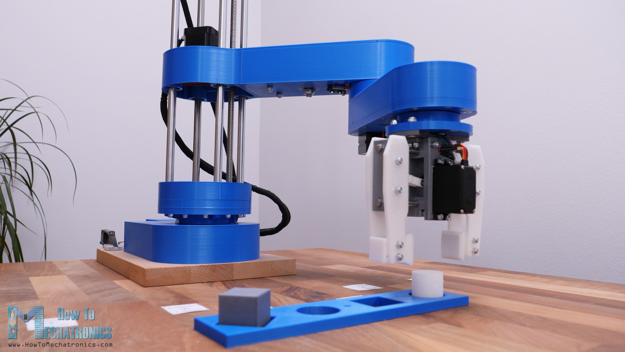
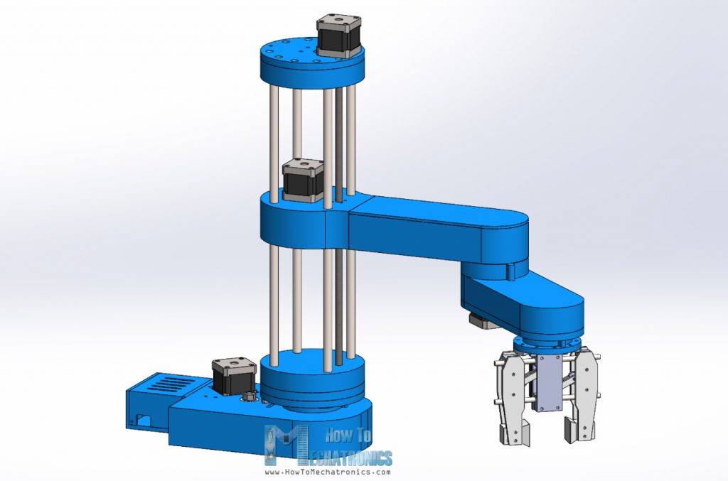
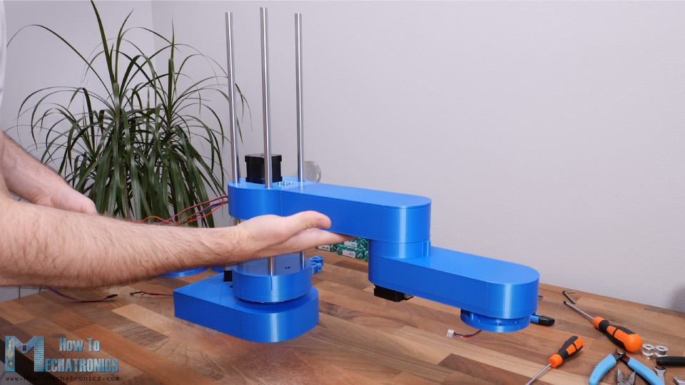
The robot has 4 degrees of freedom and it’s driven by 4 NEMA 17 stepper motors. Additionally, it has a small servo motor for controlling the end effector or the robot gripper in this case. The brain of this SCARA robot is an Arduino UNO board which is paired with a CNC shield and four A4988 stepper drivers for controlling the stepper motors.
Using the Processing development environment, I made a Graphic User Interface which features both Forward and Inverse Kinematics control. With the Forward Kinematics we can manually move each robot joint in order to get the desired position. Using the sliders on the left side, we can set the angle of each joint. The final position of the end effector, the X, Y and Z values are calculated and printed on the right side of the screen.
On the other hand, using Inverse Kinematics we can set the desired position of the end effector, and the program will automatically calculate the angles for each joint in order the robot to get to that desired position.
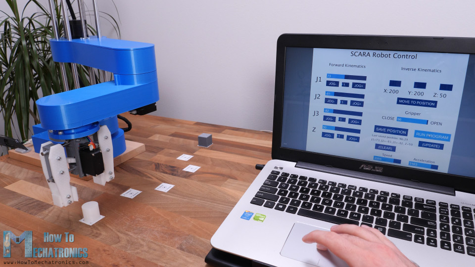
I actually made the program in a way that we can use both methods at the same time, on the same screen. The angles of the joints as well as the X, Y and Z values of the end effector are connected and always present on the screen.
Of course, the robot can also operate automatically. Using the “Save” button on the program we can save each movement or position of the robot. Then when we press the “Run” button the robot will execute the stored movements in a loop, from the first one to the last one, over and over again. We can also adjust speed of movement and the acceleration from the User Interface.
SCARA Robot 3D Model
To begin with, let’s take a look at the 3D model.

I designed this SCARA robot using 3DEXPERIENCE SOLIDWORKS which are also the sponsor of this video.
3 3DEXPERIENCE SOLIDWORKS is basically SOLIDWORKS with cloud capabilities which we get through the 3DEXPERIENCE platform. Everything works through the cloud, so you or anyone from your team can have accesses to the data or the models at any time, from anywhere in the world. The 3DEXPERIECE platform also includes many useful productivity and management apps.
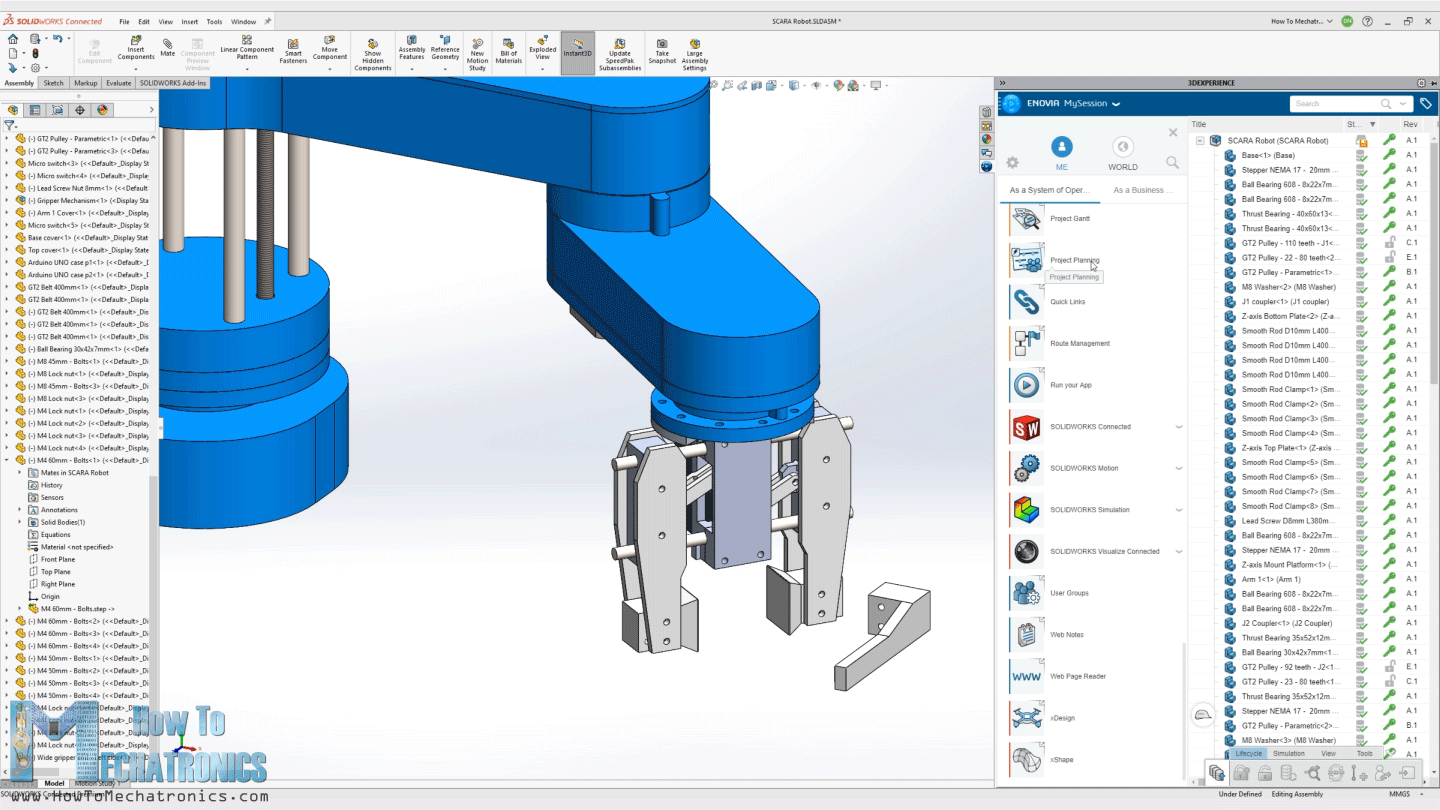
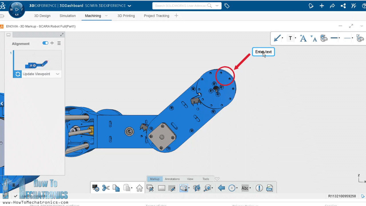
For example, the Project Planer is a great way to organize your tasks, set deadlines and keep track of your progress. With the 3D Markup app, you can view, explore and take notes of the models from any device, like a notebook, tablet or even a smartphone.
There is also a separate, cloud-based 3D modeler called SOLIDWORKS xDesign, that runs inside your browser. It can be used in conjunction with Solidworks or on its own and it’s great for modeling, anywhere, anytime and on any device.
So, big thanks to Solidworks for sponsoring educational content like this. If you would like to know whether SOLIDWORKS and the 3DEXPERIENCE platform can work for you, check the following links below.
Try 3DEXPERIENCE for free with my special link: www.solidworks.com/HTMTryNow
Learn more about 3DEXPERIENCE SOLIDWORKS: www.solidworks.com/HTMLearnMore
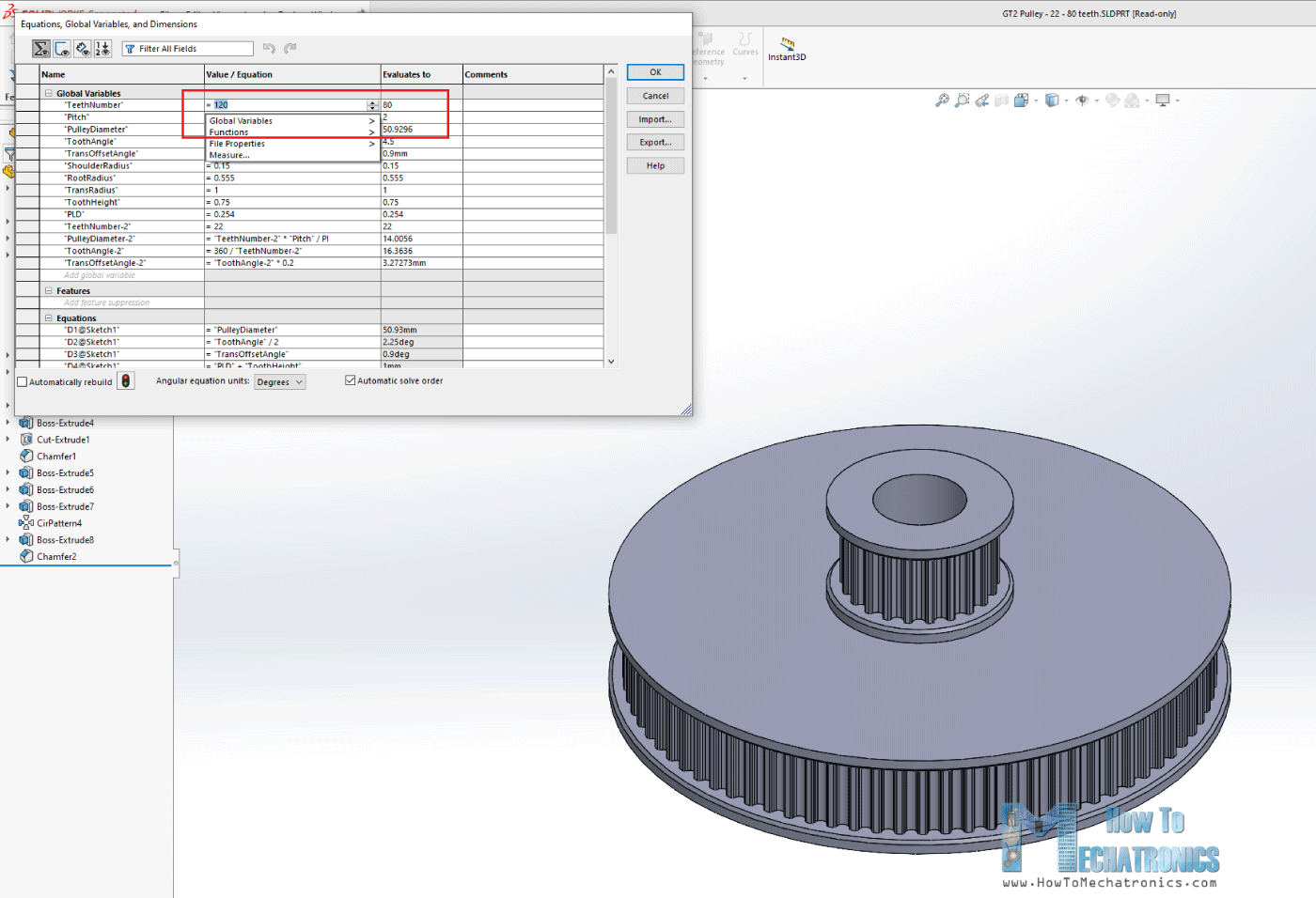
Ok, so let’s get back to the model and explain how I came up with this design. My goal for the robot was most of the parts to be 3D printed. So, everything you see here can be 3D printed even on a 3D printer with smaller printing bed. The GT2 pulleys are also 3D printable. I used parametric design to make them, so if needed we can easily change their sizes. We just have to change the number of teeth, and all dimensions will automatically update to make the pulley the proper size.
For the first joint, we have 20:1 reduction ratio, achieved in two stages with these custom designed pulleys. The two GT2 belts I use here are closed loop with 200mm and 300mm length. The robot joints are composed of two thrust bearings and one radial bearing.
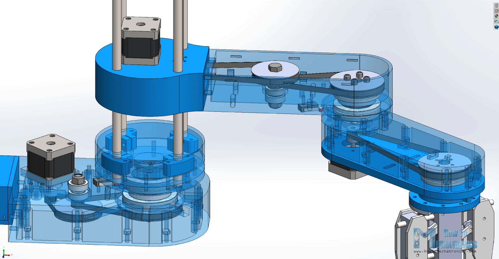
For the second joint, we have 16:1 reduction ratio, achieved in the same way, and the third joint has 4:1 reduction ratio with just a single stage reduction. The joints are hollow, so we can use that to passthrough the wires from the motors and the micro switches. For each of the belts, there are slots on which we can attach idler pulleys for tensioning them.
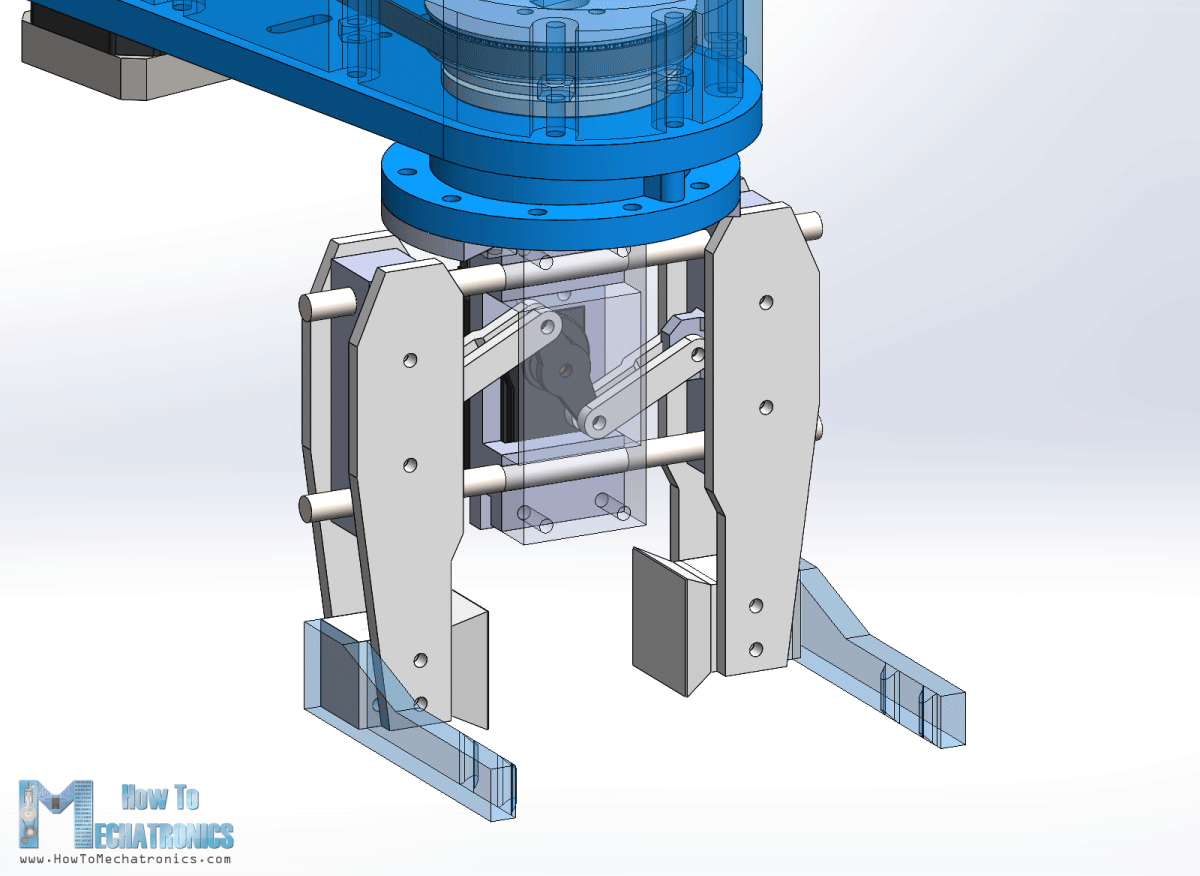
The robot gripper is driven by an MG996R servo motor and we can easily change the gripper ends to achieve different grip sizes. The Z axis of the robot is driven by an 8mm lead screw, while the whole arm assembly slides on four 10mm smooth rods and linear ball bearings. The height of the robot simply depends on the length of the smooth rods, which in this case are 40cm. The lead screw needs to be 2cm shorter in order to fit in this configuration, or if not, the Z motor can be raised by 2 cm using spacer nuts.
3D Model and STL Download Files
You can get this 3D model, as well as the STL files for 3D Printing from Cults3D.
3D Printing the robot parts
All right, so we can move on with 3D printing the parts. I used my Creality CR-10 3D printer for printing all of the parts, which is really great 3D printer with an affordable price. As I mentioned, the parts are designed to fit on a smaller 3D printer as well, for example the Ender3.
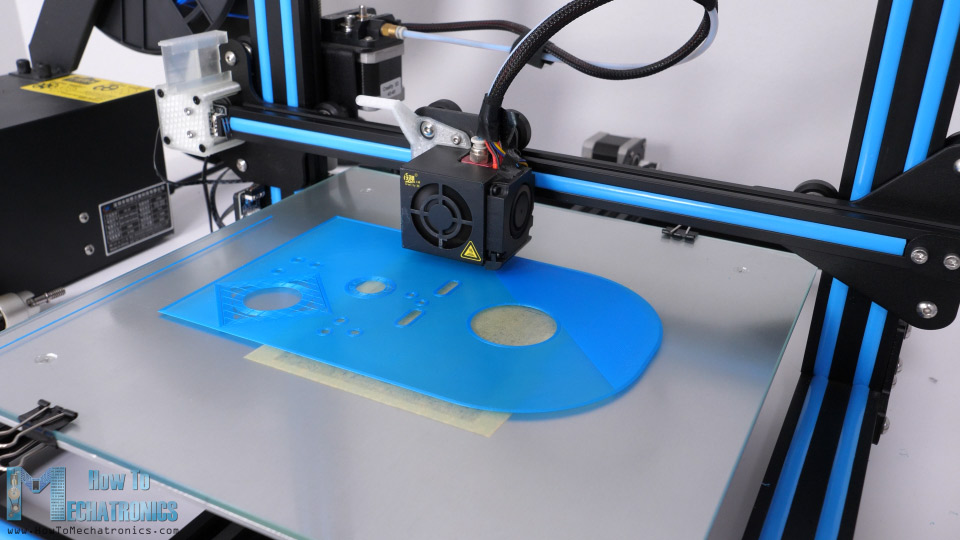
For most of the parts I used PLA+ material, the blue one, as well as normal PLA for the pulleys and the gripper. It took me around 120 hours to print all of the parts at 60mm/s printing speed. The base was the biggest part to print which took around 32 hours. However, if we increase the printing speed, we can definitely print the parts faster.
See also: Best 3D Printers for Beginners and Makers [2021 Update]
Here are all of the 3D printed parts.
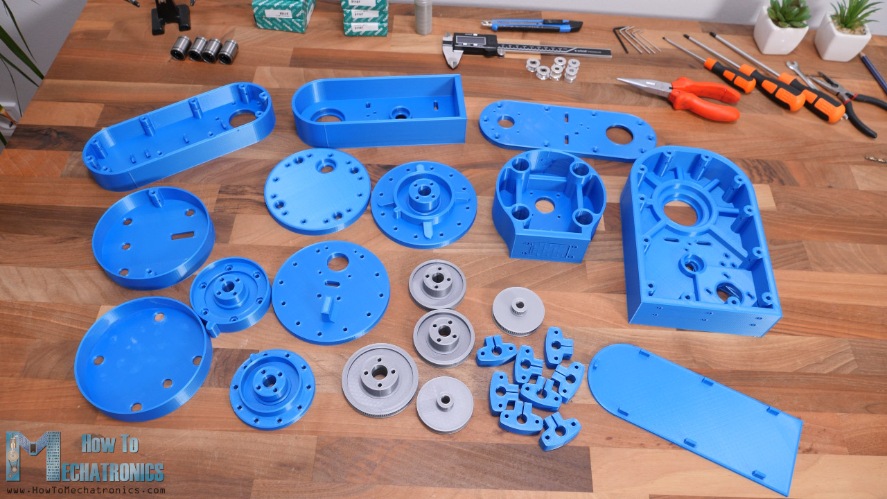
Just a quick note here, that I printed all of them with enabled Horizontal expansion of –0.1mm in the slicing software. This enables the parts to have more accurate dimensions, and fit better with the other mechanical parts like the bearings, the rods and the bolts.
Assembling the robot
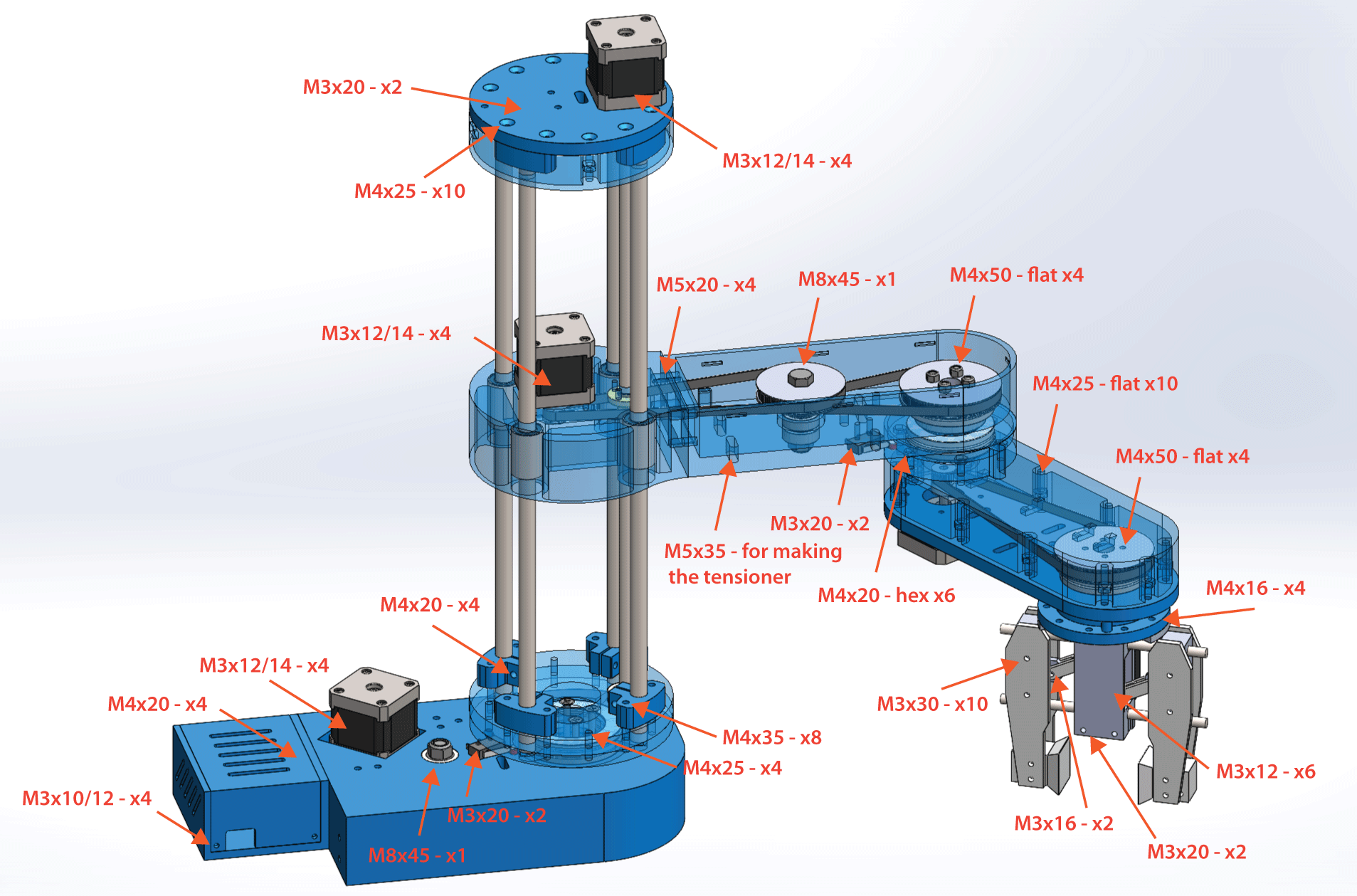
Here’s a list of components needed for assembling this Arduino based SCARA robot. The list for the electronics components can be found below in the circuit diagram section of the article.
- 4x Smooth rod shaft – 10mm 400mm……… Amazon / Banggood / AliExpress
- 1x Lead screw – 8mm 400mm ………………… Amazon / Banggood / AliExpress
- 4x Linear bearings 10mm …………………..……. Amazon / Banggood / AliExpress
- 1x Thrust ball bearing 40x60x13mm …..… Amazon / AliExpress
- 2x Thrust ball bearing 35x52x12mm …..… Amazon / AliExpress
- 5x Radial ball bearing 8x22x7mm ……………. Amazon / Banggood / AliExpress
- Various lengths M3, M4 and M5 bolts and nuts
Disclosure: These are affiliate links. As an Amazon Associate I earn from qualifying purchases.
Here are the bolts sizes required for this project:
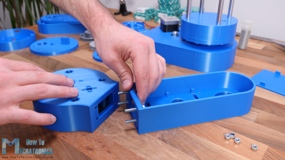
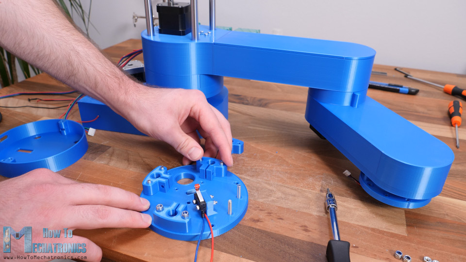
We start the assembly with base. Here first we insert a radial ball bearing with 35mm inner and 47mm outer diameter.
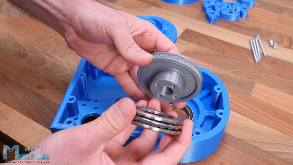
Then it goes the first thrust bearing which has 40mm inner and 60mm outer diameter. This bearing will sit between the pulley and the base.
On the other side of the base, we use another thrust bearing of the same size together with joint coupler.
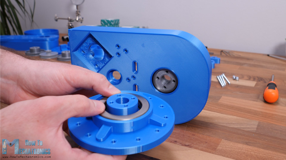
Then we can couple the pulley and upper part using four M4 bolts with 55mm length. We need to use self-locking nuts here and tighten them appropriately so the joint is sturdy while being able to freely rotate.
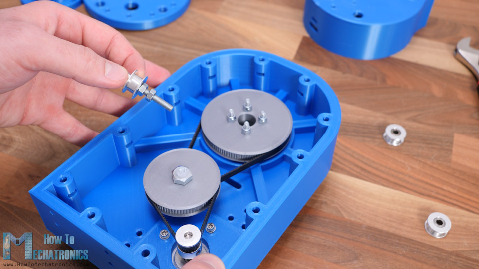
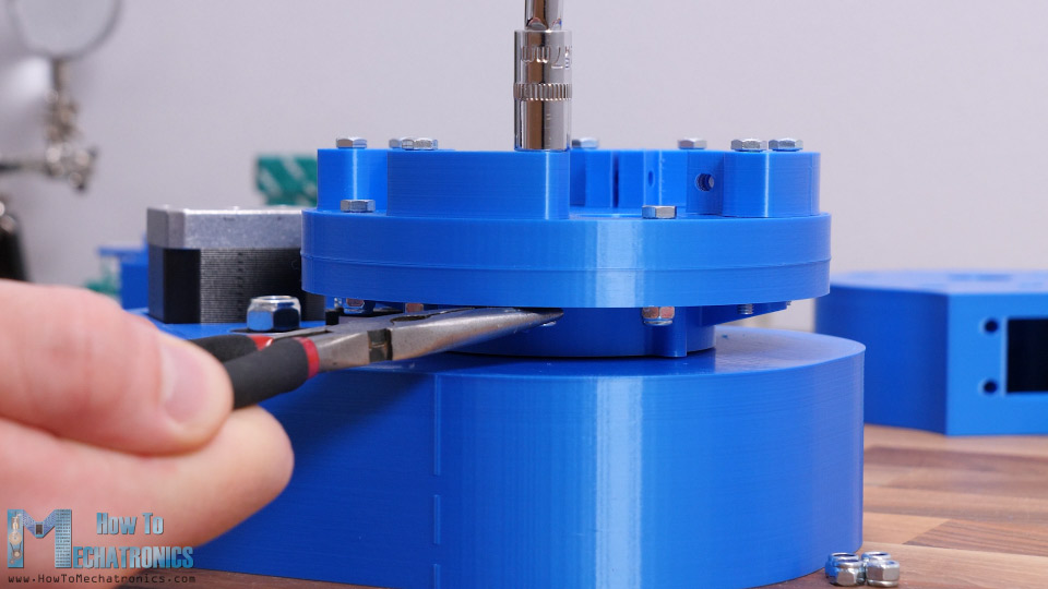
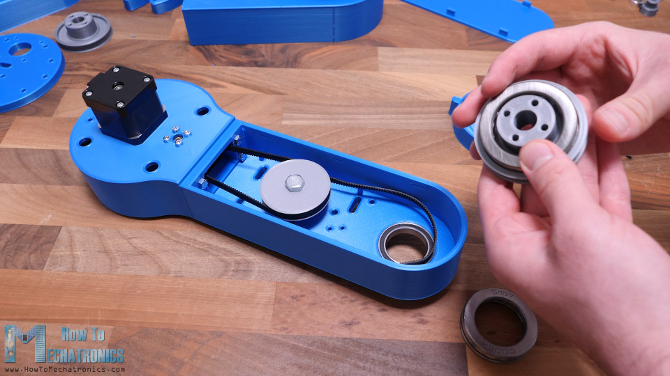
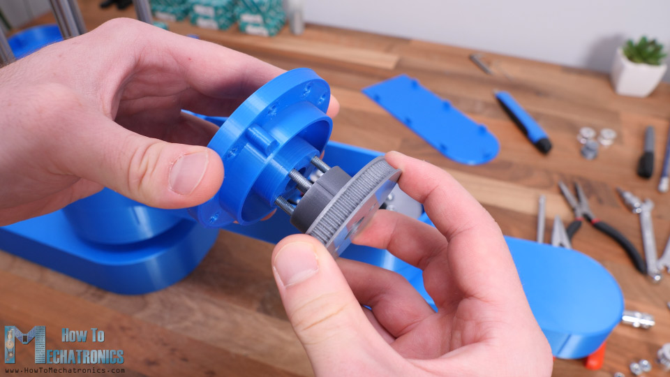
Next, we need to install the middle pulley. This pulley is paired with the joint pulley with a 300mm GT2 belt. For installing this pulley, we are using two 608 ball bearings, one on the top and the other at bottom side of the base. Then using 45mm M8 bolt, a washer and a self-locking nut we can secure the pulley in place.
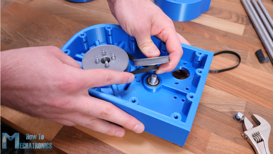
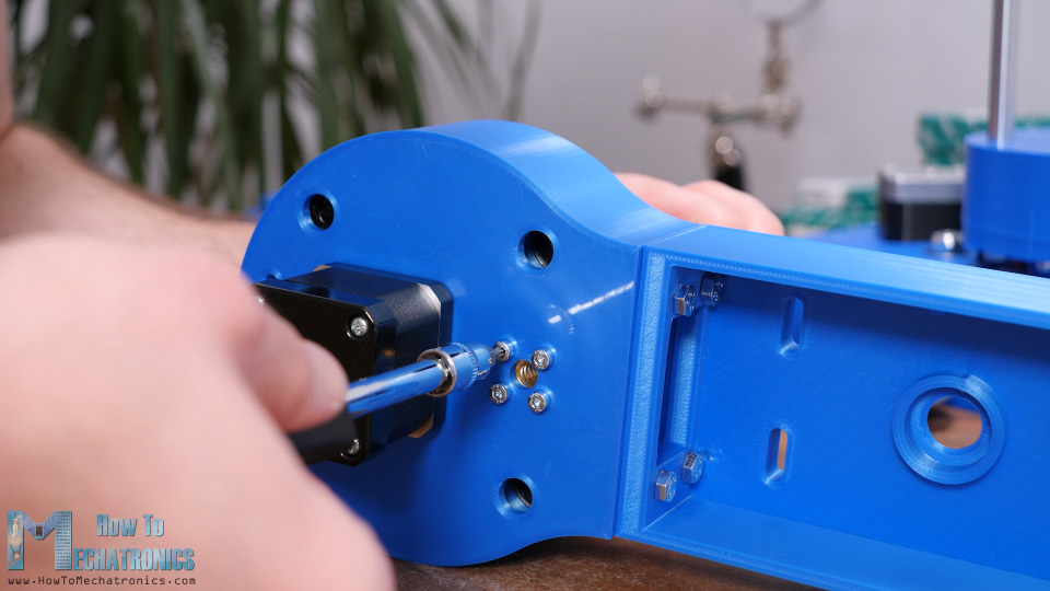
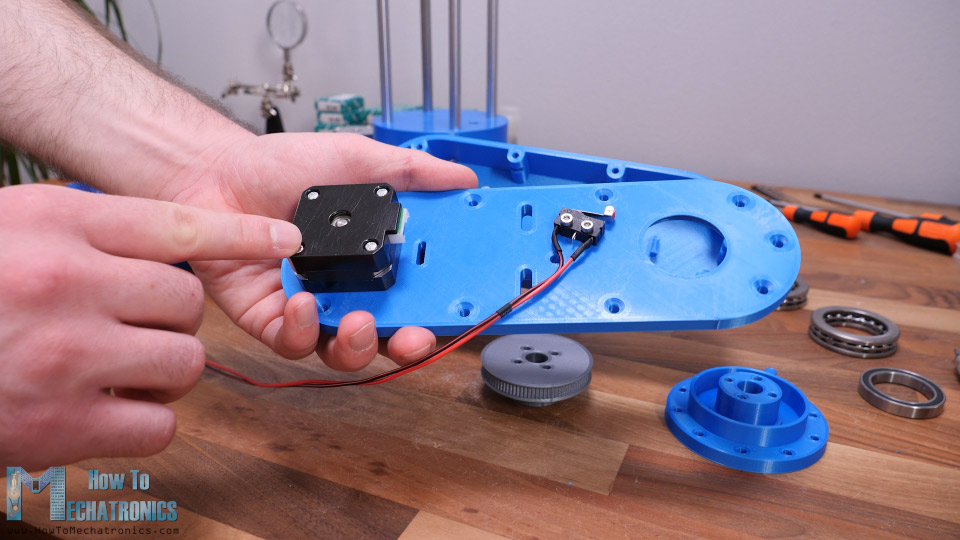
Next, we need to install the stepper motor for this joint. The stepper will be paired with the middle pulley with a 200mm belt. For securing it to the base, we need four M3 bolts.
Before tightening the bolts, we need to stretch the belt as much as we can. Just a quick note here that I actually replaced the M8 bolt for the middle pulley with its head at the bottom so that it can fit within the base.
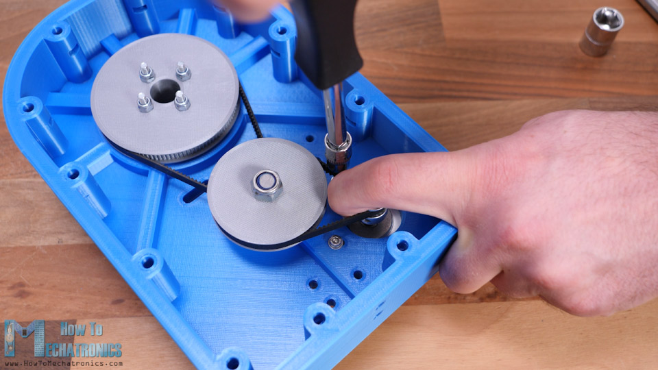
At this point, we should check whether the belts are tight enough. If not, we can use some idler pulleys to tighten them better. Here I’m using a 35mm M5 bolt and some nuts to make the tightening pulley.
It can be attached on the slots on both sides of the belt and so we can tighten the belt as much as we want. I ended up tightening the belt on both sides. With this, the first joint is completed.
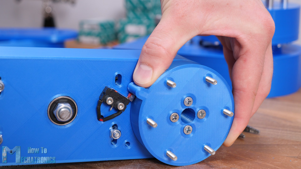
I moved on with installing the micro switch for this joint. Before securing it in place, I already soldered the wires to it, as it’s a bit tight here to do that after. We need a 20mm M3 bolts and a nut to secure the micro switch in place.
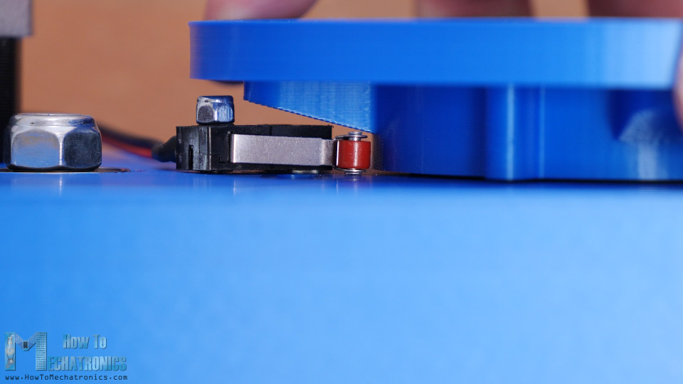
The joint coupler passes so close the switch that I ended up using only one bolt for securing the switch. On the other hole I just inserted a shorter bolt and glued it on the bottom side. That way the switch is secure enough and can work properly.
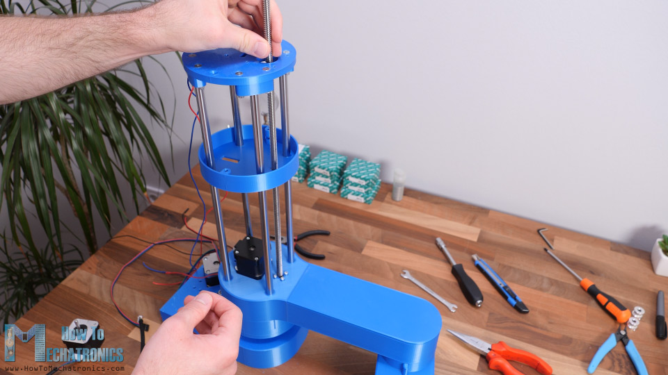
Ok, so next we can start assembling the Z-axis. First, on top of the joint coupler we need to secure the Z-axis bottom plate part.
On top of it we can secure the four clamps for the smooth rods. Then we can insert the smooth rods in place. They should fit tightly and go all the way down to joint coupler part. We can than tighten the rods with the clamps with some M4 bolts and nuts.
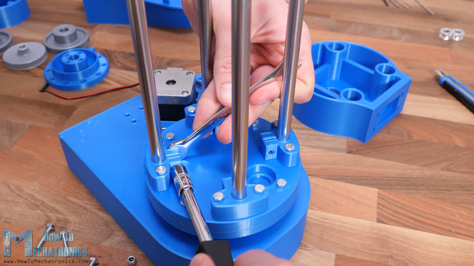
At this point we need to insert the bearing for the lead screw. To finish this section, we can just slide in a simple cover which will hide everything and give cleaner look to the robot.
Next, we can move on with assembling the first arm of the robot. The arm will be made out of two parts bolted together. The first part is where we need to install the linear bearings which will slide through the smooth rods. Inserting them in place can be a bit hard, because they fit quite tight.
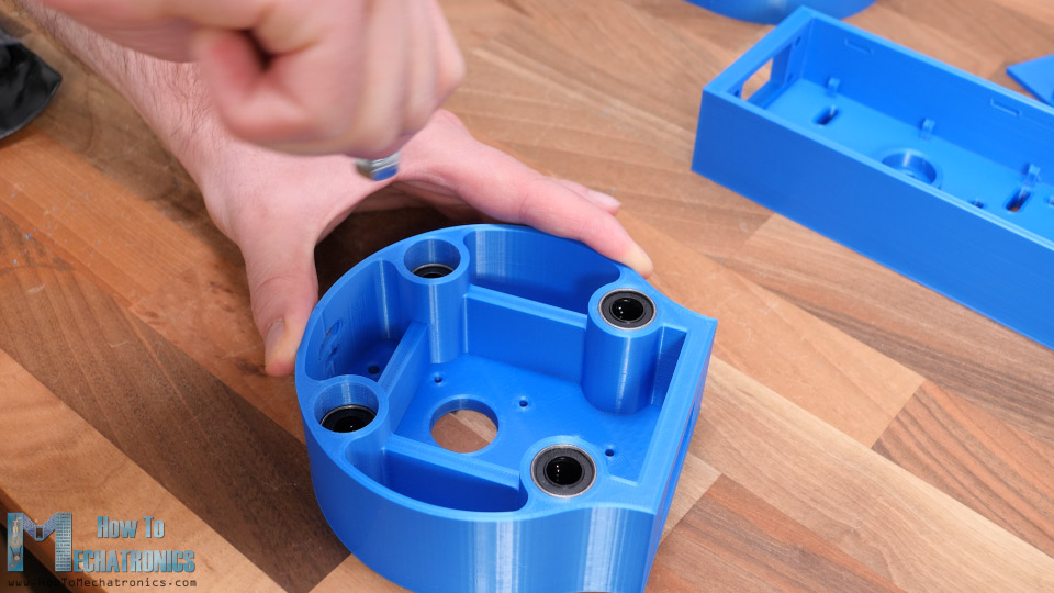
Actually, this depends on how accurate your printer can print the parts. Therefore, I suggest using the Horizonal Expansion feature when printing the parts and adjust it according to your printer. In my case, I couldn’t fit two of the bearings to go all the way down, but it’s not a big deal.
Ok, so now we can pair the two parts of arm together. For that purpose, we will use four 25mm M5 bolts.
Next, we can install the second stepper motor. Here I will use a 3D printed GT2 pulley with 20 teeth. I made this pulley using the parametric design I mentioned earlier and it works quite well. Here we also need to secure the lead screw nut in place.
Next, we can install the belts and pulleys for the second joint. Here we need one belt with 400mm and one with 300mm length. The procedure for installing them is pretty much the same as explained for first joint.
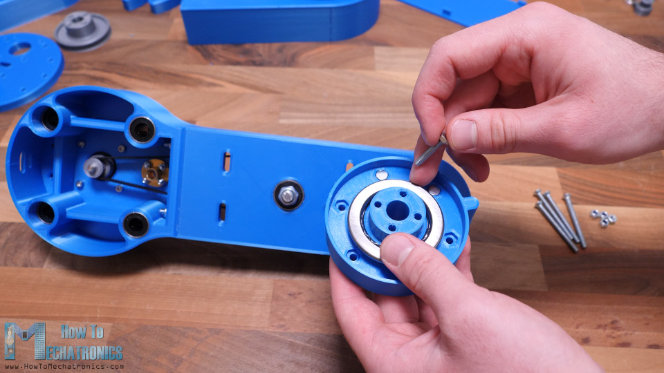
Here for the second joint and the third one, we actually use smaller bearings compared to the first one. The radial ball bearing has 30mm inner and 42mm outer diameter, and the thrust bearing has 35mm inner and 52mm outer diameter.
Before installing the second joint coupler we need to insert six 20mm M4 bolts in the hexagon slots.
They will serve for attaching the second arm to the joint. If needed, for tensioning the belts we can use the same method as explained earlier with idler pulleys. Finally, I secured the second micro switch in place and the arm number one assembly was completed.
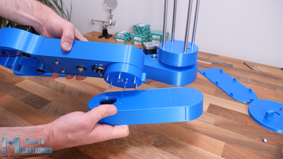
I continued with attaching the second arm to the joint coupler. Here we use those bolts in the joint coupler that we installed previously, to secure the upper part of the second arm.
At this point I wanted to test how much backlash the joints had. Sure, I expected some backlash due to the belts, but there was actually way more play between two parts of the joints. I noticed that the problem was that the holes where the bolts go, are slightly bigger than the bolts their self. In order to solve the problem, we need tighter fit between the bolts and the holes.
So, in my case I expanded the holes using 4.5mm drill, and used M5 bolts, instead of the M4 bolts, for securing the two parts of the joint together. However, I updated the 3D model so that holes are 3.5mm and you can use the M4 bolts to join these two parts together. I also went back to the first joint and did the same thing. Now the play in the joints is almost gone, except for the small backlash that we get from the belts.
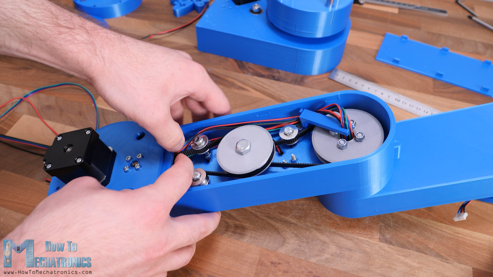
All right, so now we can continue with assembling the second arm. Here first we need to install the stepper motor for the third joint.
I’m using a smaller stepper motor in this case so that arm is a bit lighter. Still, it’s a NEMA 17 stepper motor but with shorter 24cm length.
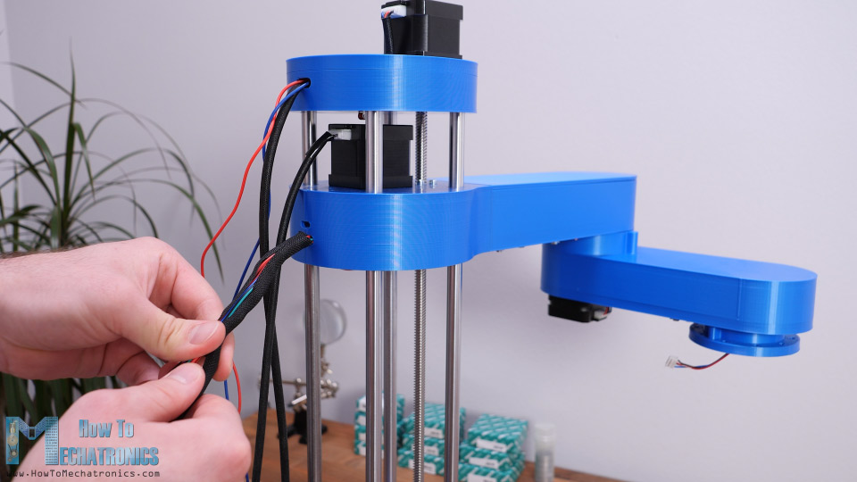
Again, we have the same procedure for installing the belts and the pulley for the third joint, except that here we use just a single stage reduction with a 400mm belt. Next, before attaching this lower part of the arm to the upper part, we need to connect the motor and the micro switch and pass their wires through second joint.
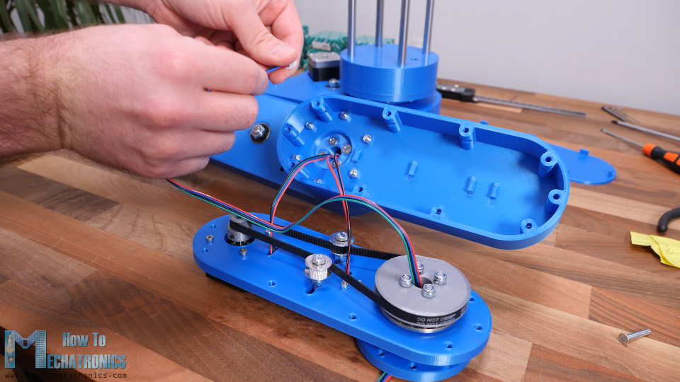
At this point, we also need to insert the wires for the end-effector. In my case I inserted a 4 wires cable from a stepper motor which I will use for driving the servo motor for my gripper which requires 3 wires.
Next, we need to insert M4 nuts in the slots of the upper arm which will serve for securing the lower part to it.
Right before merging them, we should pass the wires under those hooks so they stay away from the moving parts.
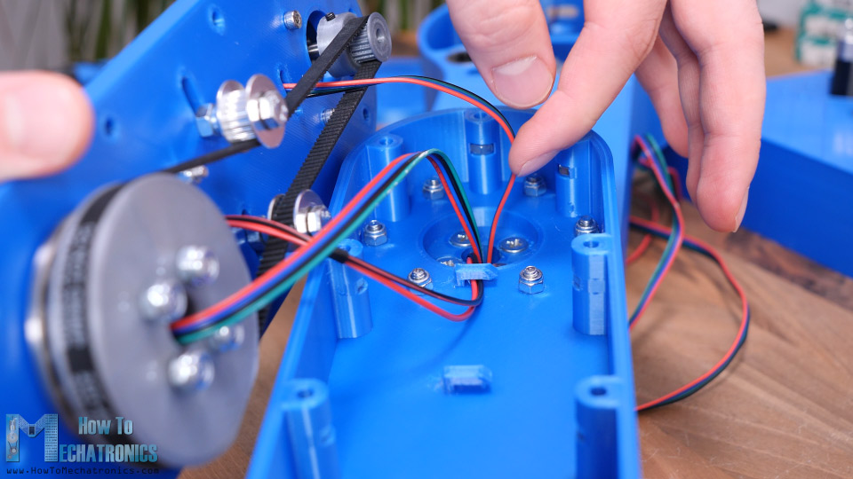
The wires coming out of the second joint can actually get caught by the nuts on the pulley, so therefore I made a simple wire holder to hold the wires away from the nuts.
We should arrange the wires to pass on one side of the arm to avoid contact with the moving parts. Finally, we can insert the cover of the first arm.
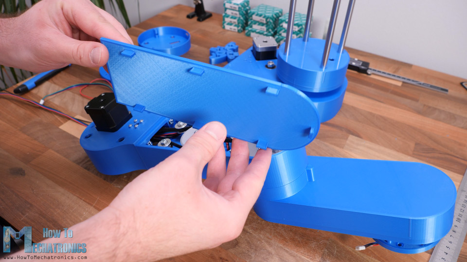
The cover is secured to the arm with a snap-fit joint. With this, the robot arms assembly is completed.
So next, we can insert this whole assembly to the Z-axis rods.
Then we need to prepare the Z-axis top plate which will hold the upper ends of the rods. Here first we can install the micro switch for the Z-axis, and the attach the for clamps to the plate.
Before putting the top plate in place, first I inserted a simple cover just like the one below, to hide the clamps, the bolts and the micro switch. Then we can insert and tighten the top plate to the rods using the clamps.
Next, we need to insert the lead screw in place.
The one I had was a bit longer, so I cut it to 38cm using a metal hand saw. Next, we can attach the fourth stepper motor in place. Here we need to use a 5mm to 8mm shaft coupler for connecting the motor the lead screw.
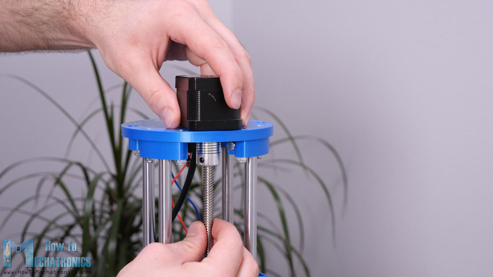
Finally, we can pass the wires through the cover and secure it to the top plate using two bolts.
Ok so, next we can do some cable management. I used cable sleeves for putting the wires together and clear the mess. I also used some zip ties for that purpose.
Before putting the wires in the cable sleeves it’s a good idea to mark each of them so you don’t connect anything wrong.
What’s left now is to make the end effector of the robot. We can actually make and attach any kind of end effector to the robot. I chose to make a simple gripper which is driven by an MG996R servo motor. The gripper is based on two 6mm rods on which the two sides slide.
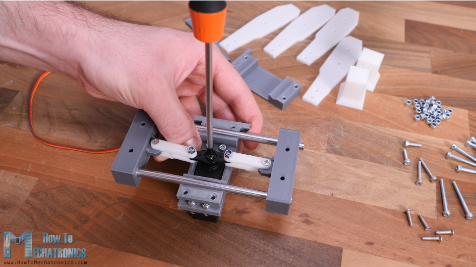
The two sliding sides are connected to the servo with a servo horn, some 3D printed links and M3 bolts and nuts. I used M3 bolts and nuts for the whole gripper assembly. You can actually find a complete list of bolts and nuts required for this project on the website article. The space for securing the bolts and nuts is quite tight, so you need some nerves for assembling some of these parts.
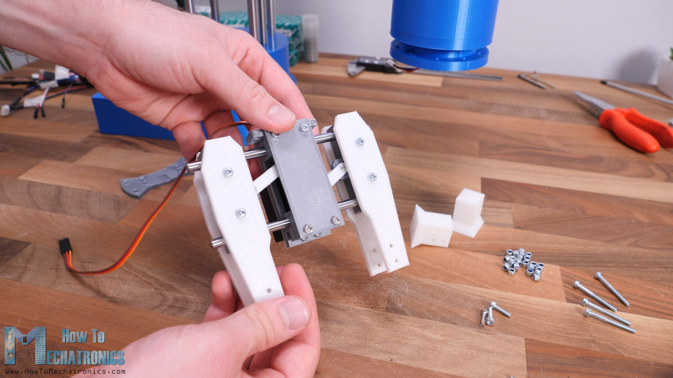
Though, what’s good about this design is that we can easily change the gripper ends. They can be wider or narrower or they can have a specific shape. We can attach the gripper to the robot arm using some M4 bolts and nuts.
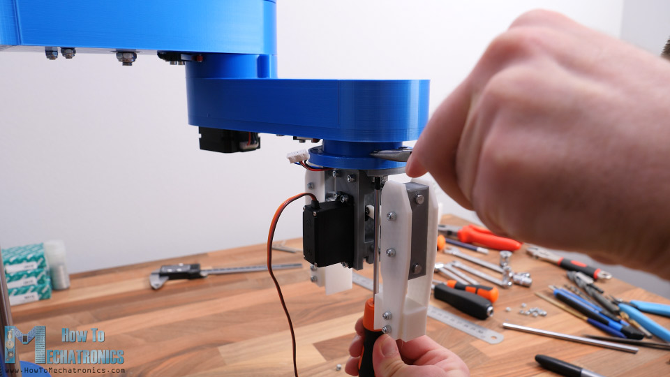
Finally, we can connect the servo motor to the wires that we installed previously.
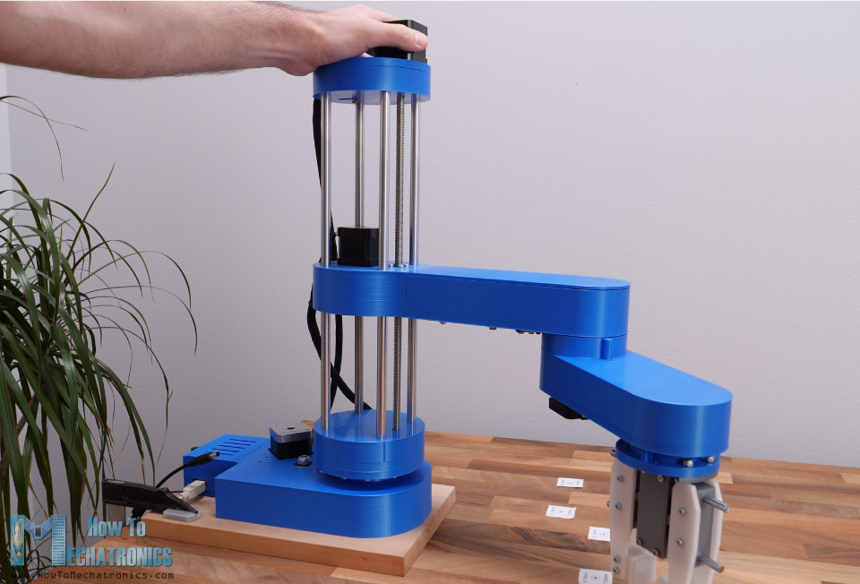
And that’s it, our SCARA robot arm is completely assembled. What’s left now is to connect the electronics components of this project.
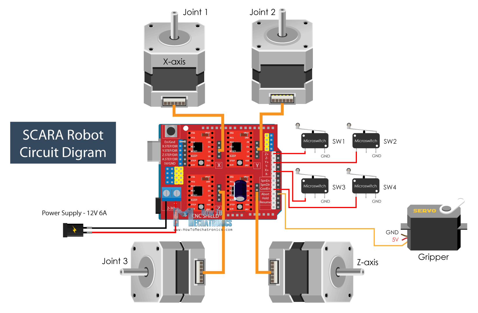
SCARA Robot Circuit Diagram
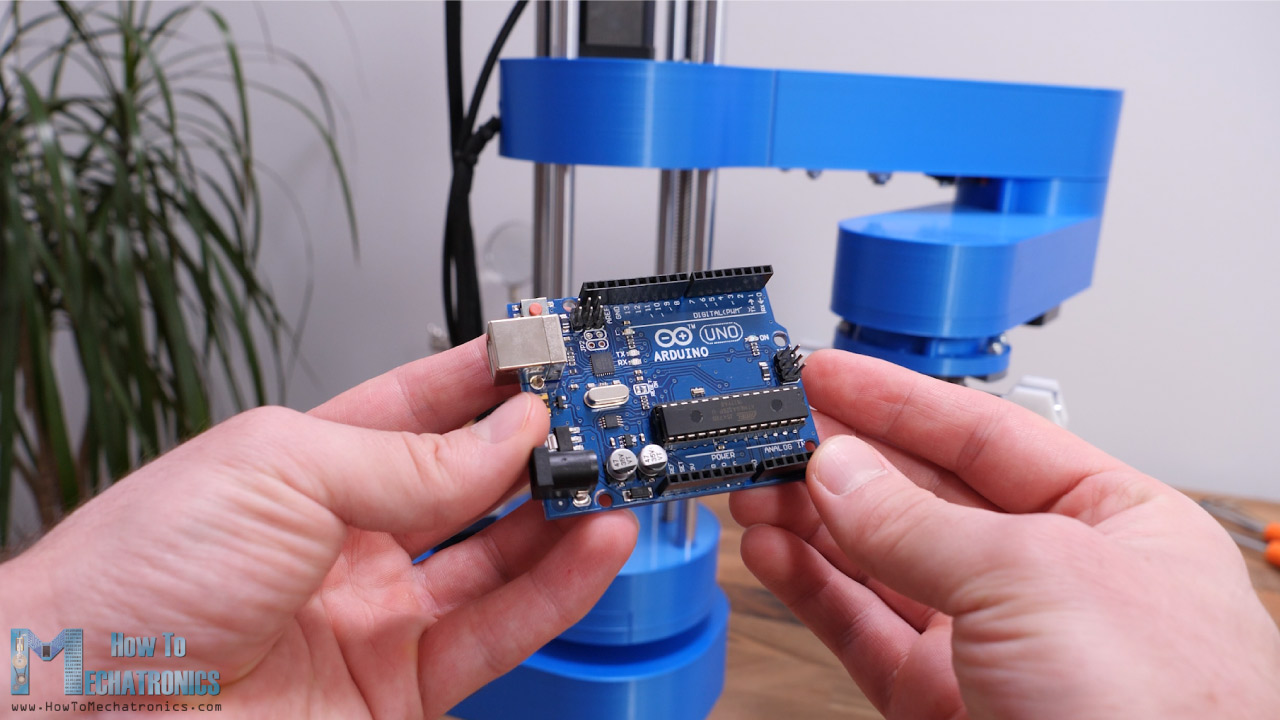
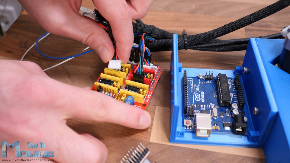
So, we will use an Arduino UNO board in combination with a CNC shield and four A4988 stepper drives.
Although it’s a robot and it seems more complicated, that’s all electronics we need for this project. It’s worth noting that, instead of Arduino UNO, we could also use an Arduino MEGA in combination with a RAMPS 3D printer controller board.
Nevertheless, I 3D printed a case for the Arduino UNO which can be easily attached to the base of the robot. I will use quarter step resolution for driving the steppers, so I placed some jumpers in the appropriate pins. Now we can connect stepper motors and the micro switches to the CNC shield.
Here’s the circuit diagram of this SCARA robot and how everything need to be connected.
You can get the components needed for this project from the links below:
- Stepper Motor – NEMA 17……………… Amazon / Banggood / AliExpress
- A4988 Stepper Driver…………………..… Amazon / Banggood / AliExpress
- Arduino CNC Shield ………………………. Amazon / Banggood / AliExpress
- Arduino Uno………………………………..… Amazon / Banggood / AliExpress
- MG996R Servo Motor………………….…. Amazon / Banggood / AliExpress
- Limit Switch …………………………………. Amazon / Banggood / AliExpress
- DC Power Supply …………………………. Amazon / Banggood / AliExpress
Disclosure: These are affiliate links. As an Amazon Associate I earn from qualifying purchases.
For powering the robot, we need 12V power supply capable of providing minimum of 4A, but I would suggest 12V 6A power supply. Of course, this depends on how the stepper driver’s current limitation is set, and I would suggest to set it at lowest level possible.
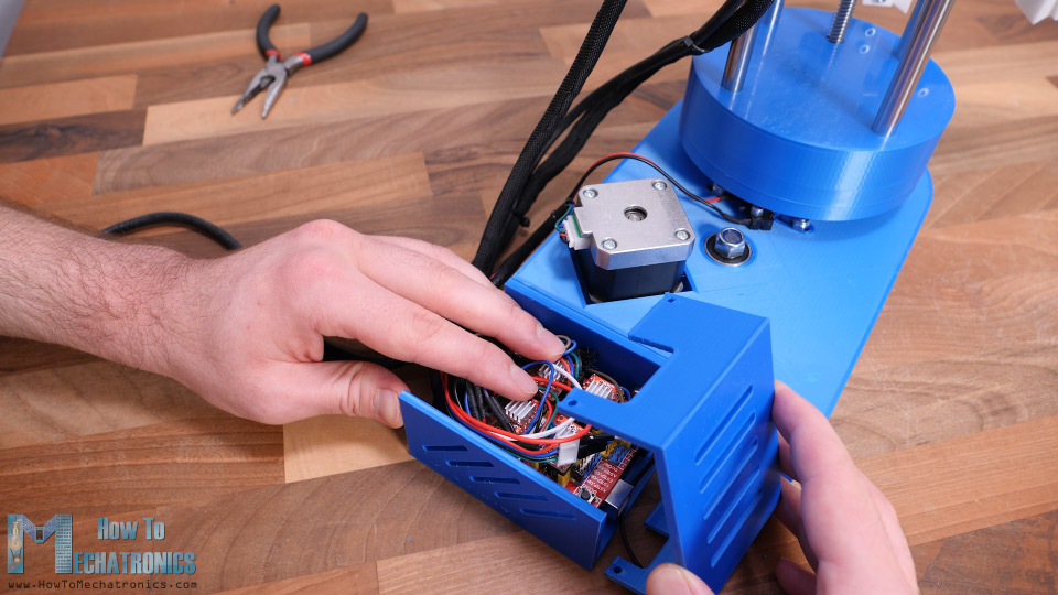
At the end, I squeezed all the wires in the case, while trying to leave the drives heat sinks free, and added the cover to it.
Finishing the assembly
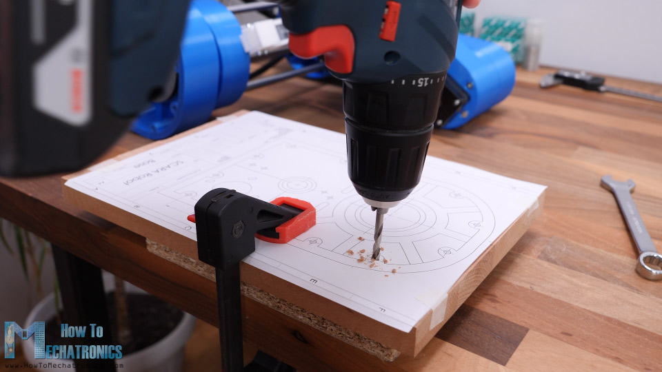
The SCARA robot is now completed, and what we need to do now is to secure the base to something. For that purpose, I will use 20mm tick piece of wood. At the bottom side of the robot base we have 12 holes available for securing it. So, I printed a drawing of the robot base, and used it to make the holes in the wood.
At the bottom side I countersunk them as I will use flat head bolts so they are flash with the wood surface. I inserted M4 nuts in the base slots and then secured the wood base to the robot base.
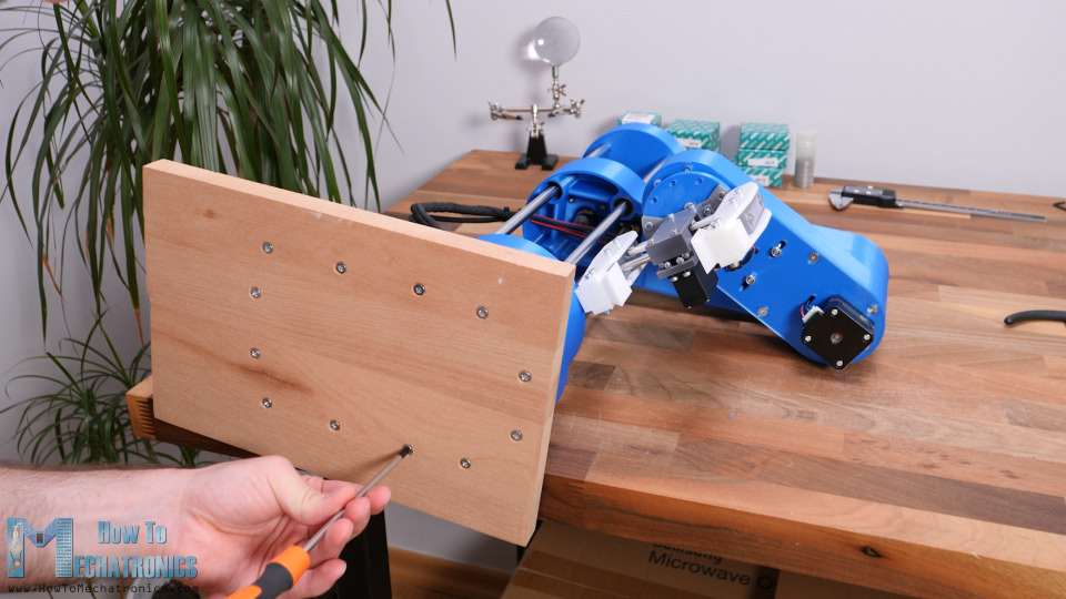
Now ideally, in order to fix the robot in place, we could bolt it to the table or I will simply use clamps for that purpose.
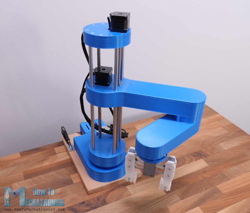
So that’s it, our SCARA robot is now completely done. What’s left in this video though, is to take a look how the robot works.
See also: DIY Arduino Robot Arm with Smartphone Control
How the SCARA robot works
There are two methods for controlling robots in terms of positioning and orientation, and that’s using forward or inverse kinematics.
Forward kinematics is used when we need to find the position and orientation of the end-effector from the given joint angles.
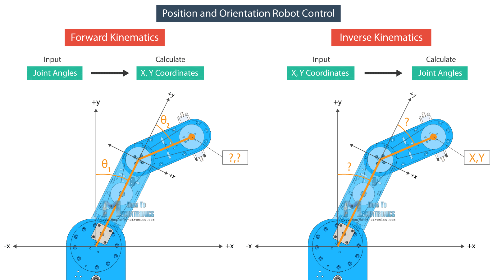
On the other hand, inverse kinematics is used when we need to find the joint angles for a given position of the end-effector. This method makes more sense in robotics as most of the time we want the robot to position its tool to a particular location or particular X, Y and Z coordinates.
With inverse kinematics we can calculate the joint angles according to given coordinates.
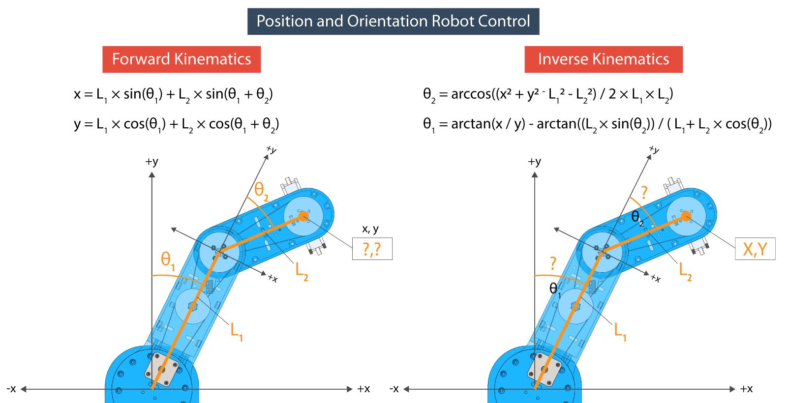
The equations that I will use for both the forward and the inverse kinematics come from trigonometry rules and formulas.
Programming the SCARA Robot – Arduino and Processing Code
At the bottom of the article you can find both the Arduino and the Processing codes.
Here’s how the equations look in a code, written in the Processing development environment.
// FORWARD KINEMATICS
void forwardKinematics() {
  float theta1F = theta1 * PI / 180;   // degrees to radians
  float theta2F = theta2 * PI / 180;
  xP = round(L1 * cos(theta1F) + L2 * cos(theta1F + theta2F));
  yP = round(L1 * sin(theta1F) + L2 * sin(theta1F + theta2F));
}Code language: JavaScript (javascript)
So, with forward kinematics we calculate the X and Y value of the end-effector, according to the set joint angles of the robots two arms, theta1 and theta2, as well as their lengths L1 and L2.
On the other hand, with inverse kinematics we calculate the joint angles, theta2 and theta1, according the given position or the X and Y coordinates.
/ INVERSE KINEMATICS
void inverseKinematics(float x, float y) {
  theta2 = acos((sq(x) + sq(y) - sq(L1) - sq(L2)) / (2 * L1 * L2));
  if (x < 0 & y < 0) {
    theta2 = (-1) * theta2;
  }

  theta1 = atan(x / y) - atan((L2 * sin(theta2)) / (L1 + L2 * cos(theta2)));

  theta2 = (-1) * theta2 * 180 / PI;
  theta1 = theta1 * 180 / PI;

 // Angles adjustment depending in which quadrant the final tool coordinate x,y is
  if (x >= 0 & y >= 0) {       // 1st quadrant
    theta1 = 90 - theta1;
  }
  if (x < 0 & y > 0) {       // 2nd quadrant
    theta1 = 90 - theta1;
  }
  if (x < 0 & y < 0) {       // 3d quadrant
    theta1 = 270 - theta1;
    phi = 270 - theta1 - theta2;
    phi = (-1) * phi;
  }
  if (x > 0 & y < 0) {       // 4th quadrant
    theta1 = -90 - theta1;
  }
  if (x < 0 & y == 0) {
    theta1 = 270 + theta1;
  }

  // Calculate "phi" angle so gripper is parallel to the X axis
  phi = 90 + theta1 + theta2;
  phi = (-1) * phi;

  // Angle adjustment depending in which quadrant the final tool coordinate x,y is
  if (x < 0 & y < 0) {       // 3d quadrant
    phi = 270 - theta1 - theta2;
  }
  if (abs(phi) > 165) {
    phi = 180 + phi;
  }

  theta1=round(theta1);
  theta2=round(theta2);
  phi=round(phi);

  cp5.getController("j1Slider").setValue(theta1);
  cp5.getController("j2Slider").setValue(theta2);
  cp5.getController("j3Slider").setValue(phi);
  cp5.getController("zSlider").setValue(zP);
}Code language: JavaScript (javascript)
Depending in which quadrant the position is set to, we make some adjustments to the joint angles with these “if” statements. For this configuration of the robot we are actually calculating inverse kinematics with just two links. The third angle which I call “phi” is be used for setting the orientation of the gripper.
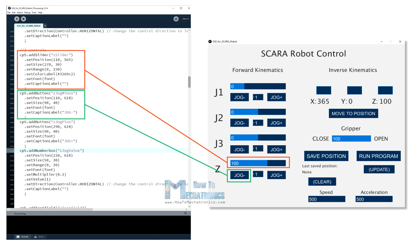
The Graphic User Interface is made using the controlP5 library for the Processing IDE. With this library we can easily create buttons, sliders, text fields and so on.
For example, we use the sliders on the left side to control the joint angles, and using the text fields we can enter the position where we want our robot to go. With each action we take here with the program, we send data to the Arduino board through the serial port.
if (gripperValuePrevious != gripperValue) {
    if (activeIK == false) {     // Check whether the inverseKinematics mode is active, Executre Forward kinematics only if inverseKinematics mode is off or false
      gripperAdd = round(cp5.getController("gripperValue").getValue());
      gripperValue=gripperAdd+50;
      updateData();
      println(data);
      myPort.write(data);
    }
  }Code language: JavaScript (javascript)
This data includes the joint angles, the gripper value, speed and acceleration values, and indicators for knowing whether we have clicked the save or the run buttons.
public void updateData() {
  data = str(saveStatus)
    +","+str(runStatus)
    +","+str(round(cp5.getController("j1Slider").getValue()))
    +","+str(round(cp5.getController("j2Slider").getValue()))
    +","+str(round(cp5.getController("j3Slider").getValue()))
    +","+str(round(cp5.getController("zSlider").getValue()))
    +","+str(gripperValue)
    +","+str(speedSlider)
    +","+str(accelerationSlider);
}Code language: JavaScript (javascript)
All this data comes as one long String at the Arduino. So here, first we need to extract the data from that string and put it into separate variables.
if (Serial.available()) {
    content = Serial.readString(); // Read the incomding data from Processing
    // Extract the data from the string and put into separate integer variables (data[] array)
    for (int i = 0; i < 10; i++) {
      int index = content.indexOf(","); // locate the first ","
      data[i] = atol(content.substring(0, index).c_str()); //Extract the number from start to the ","
      content = content.substring(index + 1); //Remove the number from the string
    }
    /*
     data[0] - SAVE button status
     data[1] - RUN button status
     data[2] - Joint 1 angle
     data[3] - Joint 2 angle
     data[4] - Joint 3 angle
     data[5] - Z position
     data[6] - Gripper value
     data[7] - Speed value
     data[8] - Acceleration value
    */Code language: JavaScript (javascript)
Now with these variables we can take actions with the robot. For example, if we press the SAVE button, we store the current joint angles values in a separate array.
// If SAVE button is pressed, store the data into the appropriate arrays
    if (data[0] == 1) {
      theta1Array[positionsCounter] = data[2] * theta1AngleToSteps; //store the values in steps = angles * angleToSteps variable
      theta2Array[positionsCounter] = data[3] * theta2AngleToSteps;
      phiArray[positionsCounter] = data[4] * phiAngleToSteps;
      zArray[positionsCounter] = data[5] * zDistanceToSteps;
      gripperArray[positionsCounter] = data[6];
      positionsCounter++;
    }Code language: JavaScript (javascript)
If we click the RUN button, we execute the stored steps and so on.
For controlling the stepper motors, I used the AccelStepper library. Although this is a great library for controlling multiple steppers at the same time, it has some limitations when it comes to controlling a robot like this. When controlling multiple steppers, the library cannot implement acceleration and deceleration, which are important for smoother operation of the robot.
stepper1.moveTo(stepper1Position);
  stepper2.moveTo(stepper2Position);
  stepper3.moveTo(stepper3Position);
  stepper4.moveTo(stepper4Position);

  while (stepper1.currentPosition() != stepper1Position || stepper2.currentPosition() != stepper2Position || stepper3.currentPosition() != stepper3Position || stepper4.currentPosition() != stepper4Position) {
    stepper1.run();
    stepper2.run();
    stepper3.run();
    stepper4.run();
  }Code language: JavaScript (javascript)
I still managed to implement acceleration and deceleration with the library, but they are not as smooth as I wanted to be.
Here are full Arduino and Processing codes for this Arduino SCARA robot project:
Wrap up
So finally, once we upload the code to the Arduino, we can run the processing program, connect the power and the scara robot will start moving to its home position.
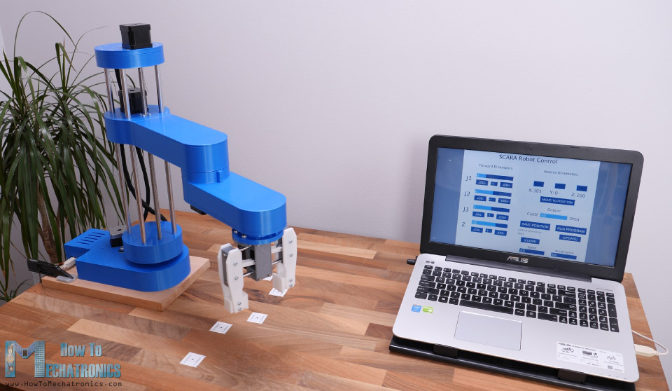
From there on, we can do whatever we want the it. We can play around manually or set it to work automatically. Of course, we can attach any kind of end-effector and make cool stuff with it. For example, we can even attach a 3D printer hot end to the robot and so make the robot a 3D printer, or attach a laser head and make it a laser cutter. I do plan try these two ideas, so make sure you subscribe to my channel so you don’t miss them in some of my future videos.
Before this video ends, I would like to give you few more notes about this project. I found the robot to be not as rigid as I expected.
I guess the problem is that almost the entire SCARA robot, the Z-axis and the arms are supported only by the first joint. The whole weight and the inertial forces generated when moving, can make quite a stress to base where the first joint is located, and as it’s just a plastic it tends to bend a little bit. Also, these belts are not backlash free so we reduce the robot rigidity with that too. However, I think the overall project is good enough so you to learn how SCARA robots work, and gives you the courage to build one for yourself.
Feel free to ask any question in the comments section below and check my Arduino Projects Collection.
Just started on this project after having completed the Perseverance Mars Rover. Great project! Regarding this robot arm, Dejan made a comment about bearings not fitting (due to plastic shrinking when cooling). With the Rover, I had LOTS of bearings that didn’t fit and the best/fastest/easiest solution was to use my heat gun to heat up the bearing holder for about 15 seconds. (When the plastic started to get glossy, that was good). Then just press the bearing into place. When plastic cools that bearing is secure and will never drop out.
Glad to hear it, I hope you had fun building these projects. And yeah, that’s a good tip for inserting the bearings in place, though I bit risky if as you might have trouble if you want to remove it.
First of all very nice Works the better part is the projecting part with Solid Works!
Just to clarify some problem that i found setting the CNC shield:
1- Need to put a jumper between EN/GND on CNC Shield otherwise the motors doesn’t move.
2- Need to Put 2 Jumpers on D12 and D13 very near to the power connection on the CNC Shield otherwise the Z Axis Doesen’t move.
3 – The pin for control the servo need to be connected on the White pin (Abort) and not to the Black one (The image Up is wrong!)
Bye!
Hello Dejan, great project, I used your model to modify it and turn it into a cylindrical robot thanks
Thanks, glad to hear it you found it useful!
Fantastic job, I already have everything functional except the servo clamp, I have done individual tests and apparently the servo motor works but when trying to control it with processing it does nothing, I would like your help please.
Glad to hear you have made it! Well year I was experiencing such a problems at times. The problem is the serial communication I guess. Try to send and receive the commands in Processing a bit different. At this moment I cannot think of what exactly you can change to get better results.
Hello.
I am fascinated by this SCARA project and it is with deep satisfaction that I followed your tutorial.
I would like to know what instructions to modify in the arduino code to use it with a 1/16 step setting instead of 1/4.
Thanks a lot.
Hey, thanks! Well you will have to change the “AngleToSteps” values which are defined at the beginning. Those values say how many steps the motor should do in order to complete particular angle. If you go from 1/4 to 1/16, that’s 4 times more steps are required. You might find the robot moving a bit slower that way as well.
Hi Dejan
Thanks very much for publishing the project. Just finished it, great learning project for a beginner like me. It’s a little bit shaky and my wiring is a mess(had to breadboard it, as the shield refused to work) but it works.
Keep up the good work
Hey, great to hear it you made it! Yeah, it’s a bit shaky, but the main purpose I guess is achieved, “great learning project”. 🙂
Cheers!
I have confirmed that my electronics are ok, as well as the baud rate and port. I also uncommented that line of processing code. But after power on, the robot still doesn’t work. I desperately need your help, I’ve lost sleep over this for days.
Hi there. Please provide some more info, for example, do you get any errors in the Processing or Arduino IDE console, or have you tried testing the drivers and motors work with a simple code to check whether they work.
There can be many things that could cause problems. You must try each components first, whether they work properly with simple codes just testing them.
What you should do is check the GUI code for where it has myPort = new Serial(this, “COM3”, 115200); commented out and uncomment it out, then close arduino and processing, reopen processing, plug in your USB and power, then run the GUI and it should work.
Hi Dejan.
Your project is superb! really enjoyed watching it (through all its versions).
I have one question that I couldn’t figure out and didn’t see anything about it above. As much as I understand, you were using the Abort pin (which is A0) to control the grabber servo – how can you do that? (isn’t the MG996R is PWM?)
Appreciate any help here – that might solve a problem I’m dealing with in my project.
Thank a lot.
Thanks!
Well you actually don’t need PWM output pin from the Arduino to control a servo motor, you can use any digital or in this case analog input to control a servo motor. The servo library uses different method for generating “PWM” signal needed for controlling the servo motor. Check my detailed tutorial for controlling servo motors with Arduino.
51108 – 40x60x13mm – x2
51107 – 35x52x12mm – x4
6807 2RS (61807) – 35x47x7 – x1
6806 2RS (61806) – 30x42x7 – x2
608RS – 8x22x7mm – x5
LM10UU – 10x19x29 – 10mm – x4
GT2-200mm – x1
GT2-300mm – x2
GT2-400mm – x2
I think this is the correct list. I just open the STEP file and checked from there
Yeah, thanks for the input!
The project looks really good; I printed all model files and really excited to make assembly. I ordered bearings according to the list above; however while checking the video, I noticed the list is missing. It would be really helpful for you to create a checklist for the mechanical and electronical parts used in the project. Thanks a lot for sharing such good projects; the community needs people like you:)
I’m doing this project with some of my high school Robotics students, this is an excellent project! I do have a question regarding the GT2 belts, are the correct belts available on Amazon, or another vendor. Thank you for sharing this project!
Glad to hear it, I hope the students will have fun and learn new stuff when building it. The GT2 belts should be available on Amazon. You need the following belts: 200mm x1, 300mm x2, 400mm x2.
Hello, I also want to make this interesting product, but I need Solidworks drawing files of each part, don’t know if you can provide it? Thank you!
You can download the 3D model and from there make your own drawing files if you need them.
it is amazing project and very good effort .we intend to make it as a graduation project .we need to know the max load . anyone who made the project and test it can help us?
Thanks. I haven’t tested the max payload, so I cannot give you any info at this moment. Go a ahead and have fun building it.
Hi Dejan, thank you for providing us with these designs. I was looking at the Arduino schematic, and the A-axis stepper driver (bottom right) looks different from the others. Does this motor use a different stepper driver than the others? My leadscrew motor on the SCARA arm isn’t working currently, so I’m wondering if the board could be the reason.
Hey, all stepper drivers are the same. What is happening with your Z-axis motor, try to connect it to a different port so you check whether your driver works properly.
Hi Dejan,
Big thank you for your fantastic project.
Children in our robotics class brought this robot
to my attention.
We have started talks about building your robot as
we have a 3d printer but when downloading the rar files for the
stl’s the rar opens with “The rar archive is either unknown format or damaged”.
I have tried different browsers but to no help.
Other rar,s we have open fine.
Thanks
Doug
Hi, thanks, glad to hear it.
I just tried downloading the file and it works fine on my computer. So I’m not sure why you cannot open it. It should work, try another computer.
Hi. That is a nice project. So, I’m graduating from college and wanted to use your mechanical project with my own control program. I will try to publish the final article. Can I, and how can I cite your project properly in the References? Thanks.
Hey, have fun building it! Sure you can include a link to my website as reference.
Hi Dejan,
I have a question regarding this part of your code:
“gripperServo.attach(A0, 600, 2500);
// initial servo value – open gripper
data[6] = 2500;
gripperServo.write(data[6]);
delay(1000);
data[5] = 100;
homing();”
I am not sure why you did not use the Arduino map() to map the 600 min value to 0 degrees and 2500 max value to 180 degrees.
Hi Dejan,
Can you please confirm my taught.
Based on your Arduino Code, the Robot Arm should go to home position without any intervention of processing code. Could my issue be caused by my stop switches (NO vs NC)
void homing() {
// Homing Stepper4
while (digitalRead(limitSwitch4) != 1) …
if the wrong switch is used we will never meet this condition ” while (digitalRead(limitSwitch4) != 1)” and therefore the stepper motor will not home.
Hello sir , what is the payload of this scara robot and how to calculate it.
I like your Robot so much sir, thanks for your works.
Hi Dejan,
I am sure it is COM issue, I used a different laptop and different USB cables. I tried different Arduino and CNC shield and still did not resolve the problem. I am running out of ideas. I really want to finish this project to share it with my student, I am will to pay anyone who can help.
Do I need to change anything on the code besides uncommenting COM3 line?
To remind you, I am able to control each joint separately using the example provided by Arduino. Here is my number and email if someone would like to contact me and I am serious, I will pay for anyone who can help
Dear Dejan
I want to thank you in person for all your hard work in contributing to learning and education. I am a teacher and I would like to use your Scara Robot in my classes for teaching robotics.
I have 3D printed all the parts, assembled them and tested every stepper motor independently, all motors and axes are working fine using the StepperMotorTest sketch provided by Arduino but when I use your Arduino and processing codes you have provided nothing happened. I am not sure what I am doing wrong.
I uploaded the Arduino code first to Arduino then I closed this sketch so the COM12 port is available for communication with processing application when transmitting serial data.
The only thing I have changed in your processing code is changed the COM3 port to COM12 poret instead and uncommented this line:
//myPort = new Serial(this, “COM3”, 115200);
myPort = new Serial(this, “COM12”, 115200);
I am not sure if I have to change anything else in the codes?
I also used a DRV8825 driver instead of A4988 driver and set its Vref to 0.8 Volts but I think this shouldn’t matter since I am able to drive my motor with the stepperMotoTest Arduino sketch.
Thank you in advance for your help.
Hey, as you have tested that the steppers work with the basic example code, then the problem is still the serial communication. You have done right with uncommenting that line and modifying it according to your COM port but not sure yet why it’s not working. Though, if you are using a MacBook this line should be a bit different.
Hi!
I like your robot and want to make the same.
i have 2 questions:
1. how to instal the second servo?
2. how to add functions “save g-code” and “load g-code” in control program?
PS
you didn’t show thet for connecting A axis we need to add two jumpers
Hey, thanks! Well you can install a second servo just like the first one is installed, you can control it if you have available pins for controlling it. As for saving and loading g-code, I though of making that feature, but I didn’t have the time for doing it. I cannot give you any tip on that as I haven’t tried implementing such a code elsewhere, but of course, it’s possible.
Are the limit switches NO or NC?
They are Normally Closed.
I have a problem with the robot arm gripper. Jaws are powered by MG-996R servo and controlled by Arduino Uno (Pin A0) via CNC Shield v3. After the command to close the jaws on the gripped object (approx. 360 mA current flows in the servo power supply circuit), the gripper locks, i.e. the jaws cannot be opened. A servo’s low noise is heard and current is greater than 200mA. I understand that the servo “wants to” reach the given position, but the object in the jaws resists preventing the servo from turning. But why does the gripper jam and it does not respond after giving the command to open the jaws? Without clamping the jaws on the workpiece, the gripper works without problems.
I am asking the author of the project or colleagues for help in solving the problem.
Hi
I have posted some issues , that I am encountering using the Scara control program , it seems to be buggy and is not full proof , please read my post and let me know if you have the same issues or have solutions for me
Thanks
Hi. This gripper designs is very similar to mine (https://www.instagram.com/p/Bx-mb4yJr74/). In my experience, the best you can do is adjust the servo value according to the size of the object (by trial-error). You can also turn off the servo after, lets say, 0.5 seconds (works for light objects). Either way the servo should not be stressed. Good luck!.
I have a problem with the gripper. When clamped on an object, the servo locks and the gripper does not open! What is causing this problem? Opening and closing the gripper without clamping the workpiece works without any problem. I am asking for help in solving the problems.
Hi
I have also built the Scara , and I have a few issues , maybe you can help
After it homes , I’d I press the gripper slider
To any value , it just drops down the z
And my gripper hits the table
Do you know what the problem is ?
Here is a post I left on how to Mechatronics
https://www.facebook.com/1590609764485967/posts/2920506971496233/?d=n
HI Raro, I am having the same issue, were you able to resolve the this issue?
Hi Raro,
Were you able to resolve your issue with gripper, I am having the same problem and I am hoping you can help. My Robot Arm goes down on the Z axis when I try to close or open the gripper.
Hi, I found that the holes of the gripper servo holder part do not match up with the gripper cover part. do you think it’s possible or am I wrong? can you check it please. thanks
How is the MG996R servo powered? Has a separate 5V power supply or is it powered from the 5V connector on the CNC Shield v3?
Sir:
you did anoutstanding and remarkable piece of work
Glad to hear it, thanks!
Hi Dean
I have some issues when using the
Processing pde Scara program , i don’t understand why sometimes when I go to a position , then move the gripper slider
It immediately goes back to
X 365, y 0 and z
Why is that ?? It shouldn’t do that
Also my gripper is opened at 0 degree and closed at 90 degree
Is there a way to change that in the program?
And what is the best way to communicate with you , I have posted in your FB, sent messages through messenger, left comment on YouTube , and also here
I need your assistance , since you are the creator , I’m not that great at programming –
Great project, built it and it works great. Had to make a few adjustments but your tutorials got me passed any issues. Would like to know if you have any problems with me showing the copy of your arm that I built with a few modifications I would like to make in my YouTube Channel. Of course, at the beginning I would reference you as the project creator and reference your channel as where I was able to learn a lot with various videos. If there is a problem then I will great my own arm which would not be a copy of yours. Please let me know what you think. One other thing I am a retired 81 year old Programmer that has a hobby of building robots and drones. I do create free videos to help others as online videos have helped me.
Thank you! Well I’m glad you found my work helpful. Sure, go ahead and share the video of the arm you made, I would love to see it. You can also share it here in the comments section so other people can see it from here. Cheers!
Dejan
Thank you for your interest in my copy of your robot. I just published the first of two videos on my YouTube Channel “LotBot Robotics”. I am not sure how it will be included but I am putting the YouTube entry from my channel here. (https://youtu.be/FKMeaDhvkUk) It is called “Using a STM32F4 Black Pill to control a SCARA Robot remotely Part 1 Feasibility”
Dejan
I finally finished my project and I ended up with four videos. However only the second one has some good demos of my copy of your robot being controlled remotely. https://youtu.be/qc-aMplBsZc can be found at my YouTube Channel “LotBot Robotics” The Part 3 and 4 are code discussions I used. Part 1 was the video I already replied about. Thank you very much developing interest project I can learn from.
Hi,
I also built the Scara Robot. I modified all the 3D models to accomodate
with all the components i had existing from my other projects, and even added some 3d features to simplify the routing of the cables in the interior of the Arms.
I am using 12mm linear shaft and flanged bushings along with a 12 mm lead screw and nut with lead 8mm and 2mm pitch. I have also a solid aluminum base frame structure which i am houing the power supply, the arduino uno and cnc shield, the step down voltage converter and fan and the ac power switch from the rear.
The Homing sequence works perfect, the only issue i am having ang i am confused.
When it fiishes the homing sequence the x,y,z are at 365,0,170. My z is slightly different than the one on youtube due to my heights of the linear shafts. Once i press the gripper value slider to open, it dives down in the z and hits the table. What can i change in the pde to stop that, it really shouldn’t do that, it should only move the gripper to where i want it to be open, closed or whatever it needs to be.Your help would be appreciated
Hi Theodore,
I having the same issue like you are having. my Homing sequence works perfect as you, the only issue I am having too is when I want to close or open the gripper then the Robot Arm dives down in the z axis. where you able to resolve this issue. I am sure a lot of people are having the same issue. I really want to complete this nice project. I am prety sure Dejan can help but he is probably very busy and I understand.
There is a lot of progress! Robot starts up! Now the mechanics need to be improved a bit.
Hello,
I love this project and you’ve inspired me to make one of my own! Before I get too far in though I’m curious about your results.
What do you think is the maximum payload of this arm? And what sort of precision/repeatability have you achieved?
It’s always nice to see new projects from you, thank you for what you create!
Hey, thanks! Well I haven’t made a test about the maximum payload. As can be seen at the end of the video, there is a little play in the arm, so realistically it doesn’t have that great precision or repeatability. Ways to improve it would be using bigger/ wider bearing at the base joint, using maybe better belts or maybe reduce the number of belts or reduction stages from two to one. Also these Z axis rails are quite good.
Hey Dejan, thank you so much for the reply!
I’ve made my own arm now- mainly based on your design! (I cheaped out in a few places haha) and it has definitely been a fun learning experience so far!
I’ve got it moving to specified coordinates no problem now. It would be awesome to see a way to implement g-code on the arm, I’m trying to figure that out but it’s all a bit beyond me right now. A tutorial like that would be amazing.
Thank you again for inspiring me to make this, it has been a lot of fun to design!
I assembled the robot. Unfortunately it does not start! Nothing happens when the power is turned on. Please help.
Hey, is there any progress with it? I mean there are so many things that could be wrong. You should start with checking whether you electronic components work properly, like your Arduino, the CNC shield or your stepper drivers. Try to use a simple code to try to run just a single motor for several steps to see whether they work. If the electronics work, you should move troubleshooting the software part, or the Processing code. Also, they simpler code or movements and make sure your baud rates and COM ports are correct.
Congratulations – great job.
According to the description, the third degree has a ratio of 1: 4. In my opinion, it is 1: 4.5 (20/90 = 4.5). Is it so?
Yes, actually that’s correct!
Good project! I may build one. The details are very good with explanation given step by step. Perhaps the base joint can be supported with a “Lazy Susan” bearing. I have used it on another 5DOF robot arm project with better results.
Nice to hear it! Yeah, the base joint needs better, wider bearing for sure.
Sorry, here english version
Hello, I follow all your projects. SCARA robot is very interesting, they are under construction. A small note: the bearing housings need to be a little bigger. For example, the bearing seat 608 should be increased by about 2 tenths already in the design phase. 22mm outer diameter could be 22.2mm design. This increase also for the seats of the other bearings. Good work, I am waiting for other excellent projects.
Buongiorno, seguo tutti i suoi progetti. SCARA robot è molto interessante, sono in fase di realizzazione. Una piccola nota: gli alloggiamenti dei cuscinetti devono essere un po’ maggiorati. Per esempio la sede del cuscinetto 608 andrebbe aumentata di circa 2 decimi già in fase di disegno. Il diametro esterno di 22 mm potrebbe essere a disegno di 22.2 mm. Tale maggiorazione anche per le sedi degli altri cuscinetti. Buon lavoro, sono in attesa di altri ottimi progetti.
example
Love it! Can you explain the joint design? I understand the thrust bearing but why do you also need a radial bearing? More stability? Unfortunately my Prusa Mini can’t print this project so I need to design a smaller version. Last year I tried to use Processing to control a cartesian CNC but failed… will have to try adapting your code 🙂
Hi Dejan,
Thanks for the updates to your post! I just completed the build and it works pretty good with reasonable backlash to the main joint. Still it feels pretty sturdy with fast movement on the arm joint. Other thing I noticed mechanically is that ‘cheap’ Z-rod axis are also potential to give some ‘wobble’ during Z-movement ;).
About your Arduino code, I had to trim down the stepper1 speed and homing speed to surely half of it. Not sure what is different there.
I used (in setup method):
stepper1.setMaxSpeed(200);
stepper1.setAcceleration(500);
and in ‘homing’ method:
stepper1.setSpeed(-200);
stepper1.runSpeed();
stepper1.setCurrentPosition(-1978); // When limit switch pressed set position to 0 steps //-3955
I also had to trim the stepper1 position on the limitswitch back to half. Not sure what caused that.
Can you confirm or suggest otherwise on the two ‘stepper1’ tweaks?
Cheers!
HI,
Firstly it is great work sir.
In stl zip file is missing “gripper wide end.stl” for left/right side
can you upload it please?
Thank you
Hey, thanks. Yeah, that file was missing, thanks for the report. I’ve updated the files.
Really nice project, lots of learning
Hi,
Great project, Im just printing the parts, but I’m missing the stl of the arduino box an smooth rod clamps.
Could you please upload these?
thanks
Hey, thanks! I’ve updated the download file and included those files.
Hi
Your STL files are missing the clamps for the 4 rods..
Ralph
Hey, thanks for reporting it, I’ve just updated the files with the clamps.
Hello Dejah,
Very nice project, but there is some questions about formulas for forward and inverse kinematics.
Forward kinematics:
If angles are given as in pictures, then “x” coordinate proportional to the sinus of respective angles and it would be: x=L1*sin(theta1)+L2*sin(theta1+theta2), same thing(means cosine) for the “y”. Probably, the angles should be Pi/2-thetas
Inverse kinematics:
1) Lengths L1 and L2 should be squared (like in your program)
2) Minus, there should be -L1^2 and -L2^2 (as we can see in your program)
3) As in Forward kinematics, you should change the angles in the pictures
Hey Viktor, thanks for the input, you are right. I’ve messed up a little bit those formulas. I updated the image now. Instead of changing the angle in the picture though, I changed the x and y formulas, which I hope won’t cause confusion for the other people. I guess the angles adjustments I had to do in the program after the formulas are caused because of how these formulas are set. However, the formulas are correct now so people can make changes in the code if needed appropriately. Thanks again, cheers!
thank you, this a good work
Hello Dejan,
Nice and amazing project! Would it be possible to connect all this to your custom made pcb you made in the Arduino robot and mecanum wheels project? I was wondering if I could connect it to my phone and control it using bluetooth…
Dear Author,
One STL file is missing – those 4 small elements to keep rods in place
That’s right, I’ve just updated the files, thanks!
Hello Dejan, Awesome project and really great how you described the project and the build instructions. I’m now trying to build the robot as well and some printers are buzzing away right now.
Am I correct to detect that the 8mm rod 400mmm clamp-model (8x to be printed) is not in your STL export archive?
Hey, thanks! Yeah, they were missing. I’ve just updated the files now.
hey love the project started printing the parts yesterday 🙂 i have a question: the kinematic model you used in the processing ide, would it be possible to implement that directly in the arduin itself? i want to hard program the positions the robot drives to and hope i wont need a pc or raspberry pi for that? thanks for sharing this project 🙂
Hey, thanks! Sure, you can do that. You can calculate the kinematics model with the Arduino and do whatever you want with it. I used the Processing IDE just to make an easier GUI for controlling the robot.
Awesome project!!!. Little question, maybe i miss that part, but how much PLA (kg) do we need for making our own SCARA?
Thanks! Hmmm, I didn’t keep track of that, so I couldn’t tell exact number. Something around 1 to 1.5kg I think.
Hello
It seems the stl file link does not work..
can you something about it?
thanks
You can’t download them or you can’t open the files? In the first case, try to use different web-browser for downloading them.
Hello Dejan, I’m currently sourcing all the parts to build this robot. Q: what is the width of the GT2 timing belts? Thanks for publishing yet another great project!
Hey, the width of the GT2 timing belts is 6mm.
Hello Dejan,
Great project, great work, you did very well. Looking forward to the hot end for 3D printers and the laser cutter 🙂
How about a vacuum suction cup?
Greetings from Germany
Eric
Awesome project. Can’t wait to build mine. At what layer height and infill % did you print the parts at?
Thanks! I printed the parts at 0.2mm layer height and around 30% “cubic” infill.
Have fun building one!
Very cool project. Thanks for sharing 🙂
Can you get a turtorial for funsion360? I think it a wonderful software. Because i found you use it in every project.
Great project I am going to give it a try!
I couldn’t find the list of hardware, bolts and nuts. Could you send me a link to that please
Thanks!
Once again another awesome project of yours that i will want to build. In reference to the first Z-axis joint flexing to much, I’ve found that using a slew bearing takes all the strain of the servo.
Thank you, have fun building one!
Hi,
Excellent work, very well explained. Can you please tell me
how do I use the GUI Scara robot interface ? I never worked with .pde files. How do I run the .pde files ? Also if I build the Scara can I use different lengths for the arms and modify those parameters in Arduino ?
what parameters would I need to modify
Hey, thanks! Well the GUI is made using Processing IDE, so you need to install it on your computer and then run the program on it. The Arduino is connected to the computer and through the Processing IDE they are able to communicate through the serial port. For more info about this you can check some of my other tutorials related to this topic, you can use the “Search” button function on the website.
As for the arm lengths, sure you can modify them. In the Processing code you just have to change the L1 and L2 parameters to match with your actual lengths so the Forward and Inverse kinematics is calculated correctly.