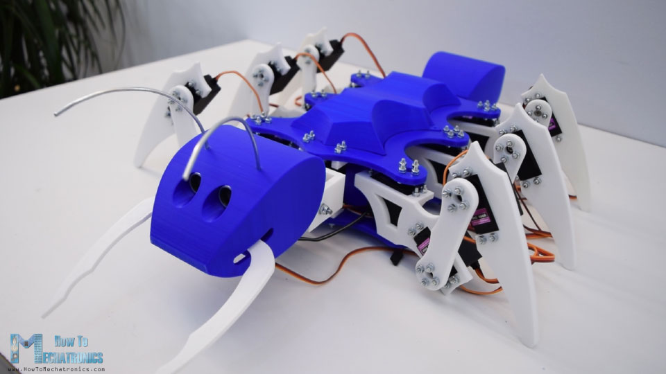
In this tutorial I will show you how I built an Arduino hexapod. As the name suggests, the hexapod has 6 legs but in addition to that, it also has a tail or abdomen, a head, antennas, mandibles and even functional eyes. All of this, makes the hexapod look like an ant, so therefore we can also call it an Arduino Ant Robot.
You can watch the following video or read the written tutorial below.
Overview
For controlling the robot I made a custom-built Android application. The app has 4 buttons through which we can command the robot to move forward or backwards, as well as turn left or right. Along with these main functions, the robot can also move its head and tail, as well as it can bite, grab and drop things and even attack.
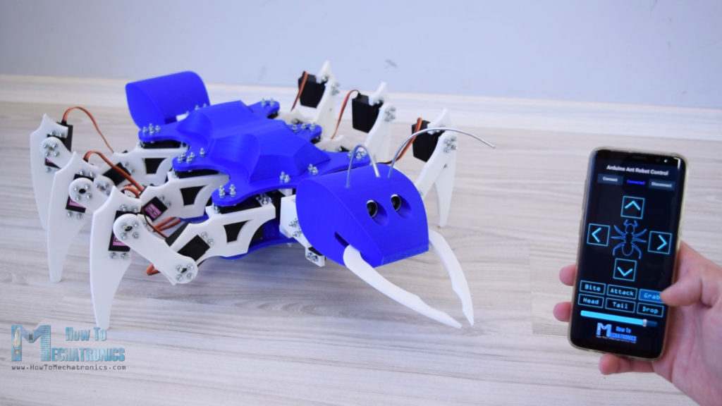
As I mentioned earlier, the robot has functional eyes, or I specifically designed the head to fit an ultrasonic sensor. So if we try to touch the robot head or get our hand close to the sensor, the robot will initially prepare for an attack.
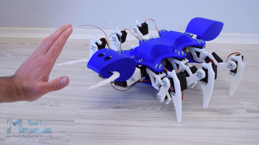
If we move back, the robot will dismiss the attack, but in case we get our hand closer to it, it will attack and bite us. So how cool is that? Stick around and you will find out exactly how I build it and how everything works.
Arduino Hexapod – Ant Robot 3D Model
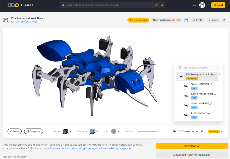
As usual, I started by designing the hexapod using a 3D modeling software. The hexapod has 6 legs and each of them consist of 3 joints or 3 servos. That means we need total of 18 servos and in my case I used the MG996R servos.
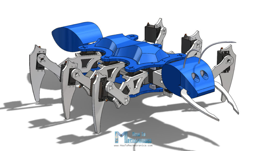
On the back side we have the tail which is driven by another MG996R servo. The head of this ant robot has two degrees of freedom, or it can roll and tilt, and again it’s driven by two more servos. So we need total of 21 servos for this project, type MG996R and additionally one smaller SG90 micro servo for the mandibles.
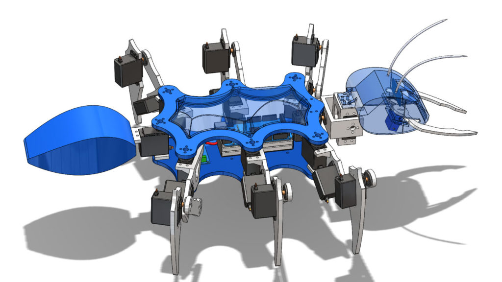
Here we also have the eyes of the ant which are design to fit an HC-SR04 ultrasonic sensor. All of the parts are assembled between two plates and additionally I made an interesting curved cover for the top plate in order to hide all of the wiring, the Arduino and the battery between the two plates.
You can find and download this 3D model, as well as explore it in your browser on Thangs.
STL files:
3D Printing the Parts
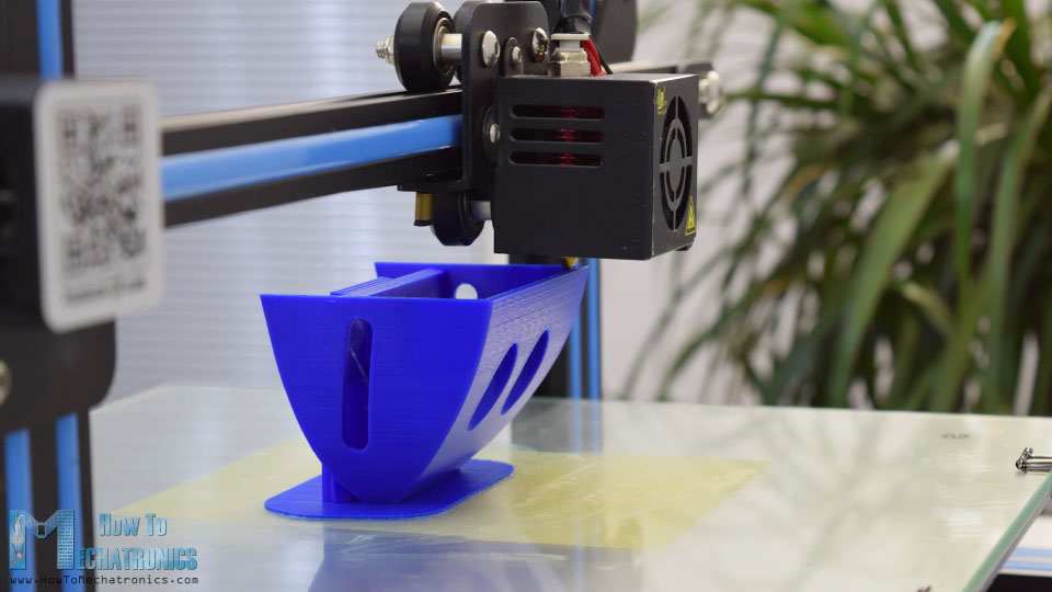
I guess you already know what’s next, and that’s 3D printing the robot parts. I used the Creality CR-10 3D Printer for all of the prints and it did a great job. The most difficult part to print was the head, because I wanted to be a single print.
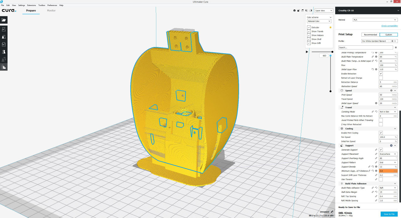
For that purpose I had to use a Support Overhang Angle of 60 degrees as well as some support blockers. Anyway, the Creality CR-10 did a great job and the head turned out perfectly.
Assembling the Arduino Hexapod
Once we have all of the parts printed we can move on with assembling the hexapod. I started with assembling the legs. For securing the servos to the printed parts I used M3 bolts and nuts, as well as spring washers. The length of the bolts needs to be at least 12 mm and in my case I used 16mm long bolts.
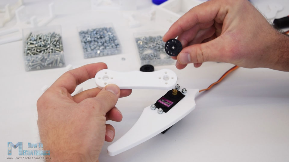
We need around 200 bolts for the whole assembly. For connecting the links to each other we use the round horns which come along with servo package as accessories. However, we need to drill 3mm holes on each of them so that the bolts can pass through, or we can use metal round horns which have M3 threads and can be bought separately.
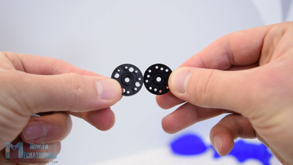
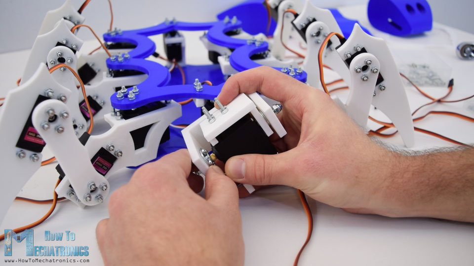
When securing the links to the servos we need to make sure that we always connect them at the same position and they have the full range of motion.
We should notice here that the servos have a small triangular support on the top side which needs to be removed. I used a simple utility knife to do that, so in that way the servos can be placed flash with the printed parts. Before inserting the third servo in place, we first need to insert an M4 bolt which will be used for connecting the leg with the base plate.
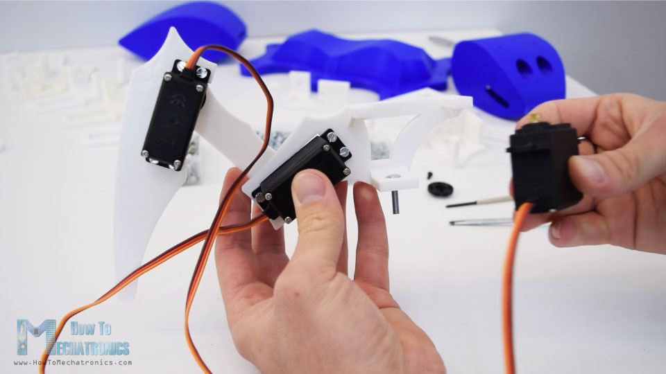
Here’s how the leg assembly should look like. It’s actually very easy to assembly it but now we need five more of them.
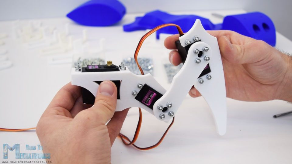
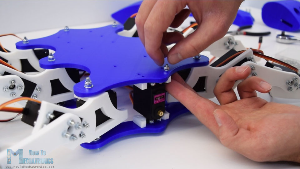
Once we have all of the legs ready, we can move on with installing them to the body of the robot, or the two plates. First we need to secure the round horns onto the top platform using the same method as previously, with M3 bolts and nuts. Then we can simply connect them to the servos shafts using the bolts, but before we do that we need adjust the position of the servos to be exactly in the middle.
This is needed so that we can get the full range of motion of the servos and also will reduce the adjustment or the calibration process when programing the Arduino.
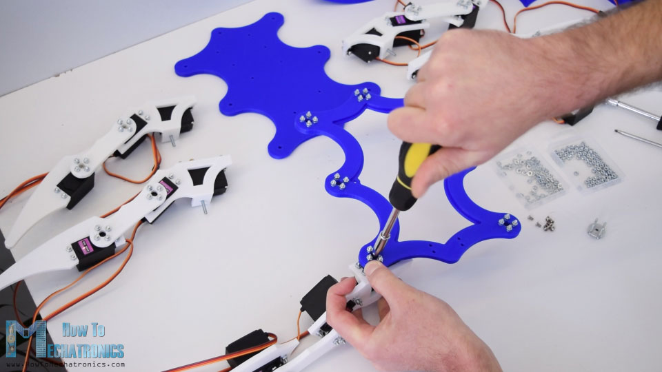
After securing the legs, this project already started to taking shape and look like a hexapod.
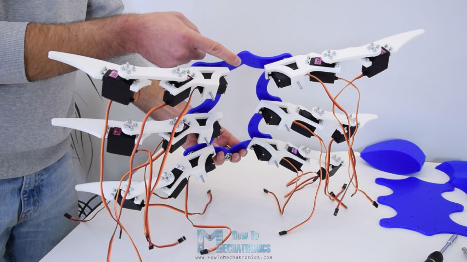
There is one more round horn of the back side and that’s for the tail servo which also needs to be secured that this point.
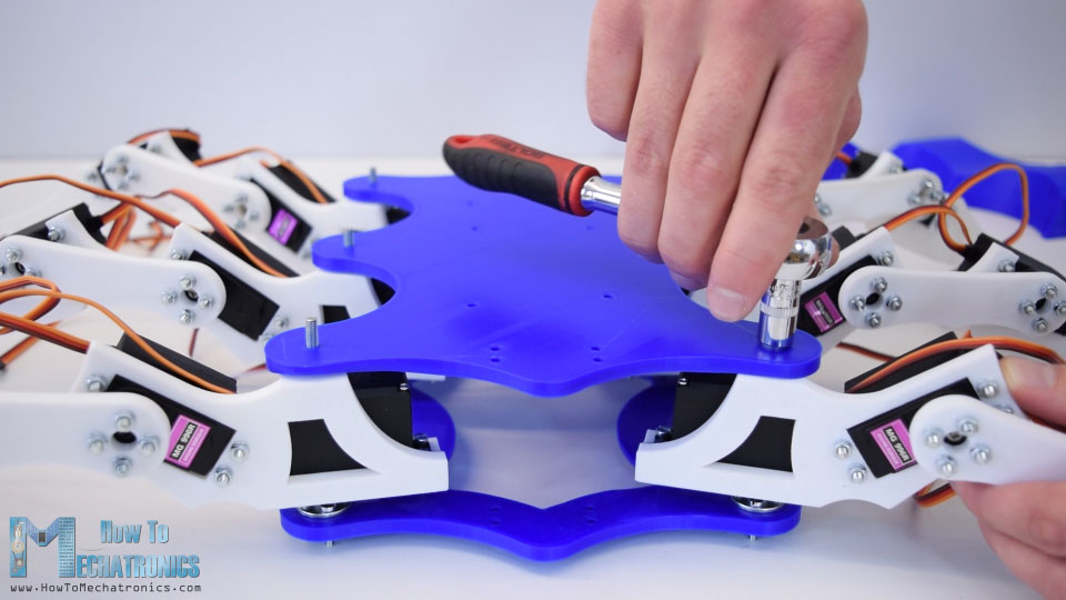
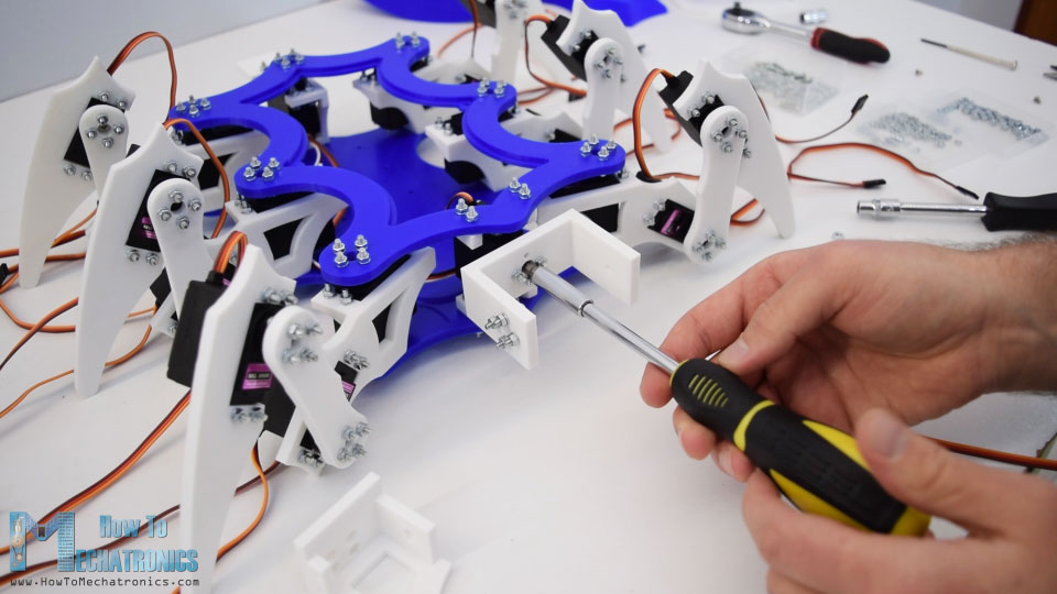
Next we need place the hexapod upside down and so we will be able to insert the bottom plate through the M4 bolts of the legs. Then I secured the legs to it using some plain washers and self-locking nuts. We should be careful how much we tighten these bolts because these are actually the pivot joints and the legs should also be able to rotate while being secure enough.
Next we need to install the first servo for the head and that’s for the roll movement. This servo should be placed perpendicular to base plates, so for that purpose I made two small plates which are first secured to the servo. Then we can insert the servo between the two plates and we can easily secure it with the M3 bolts and nuts.
Then we have a U shaped bracket and here we need attach two round horns for connecting the two servos for the head. Again before securing the bracket to the roll servo we need to make sure that the position of the servo is in the middle so it can rotates 90 degrees in both directions.
Next is the tilt servo bracket. So here first we need to insert an M4 bolt and secure it to U shaped bracket. Before mounting the tilt motor we also need to insert four M3 bolts which will be later used for securing head. Then we can insert the tilt servo to the bracket and carefully fit the shaft to the round horn. It’s a bit tight here but the U shaped bracket can helpfully flex a little bit.
Lastly we need to secure the servo with the M3 bolts and with that the head mechanism is completed. Now it can both roll and tilt.
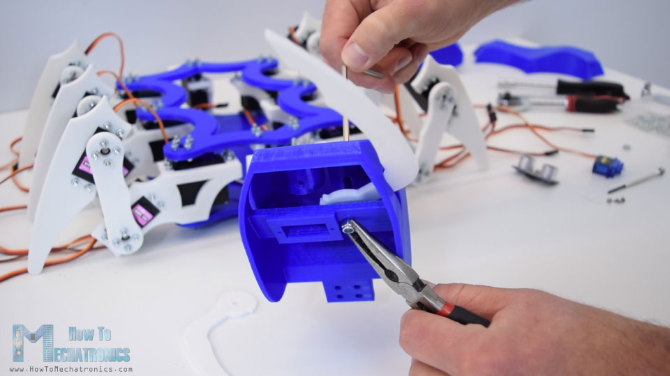
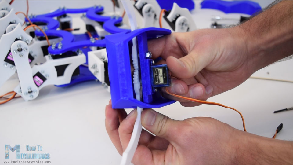
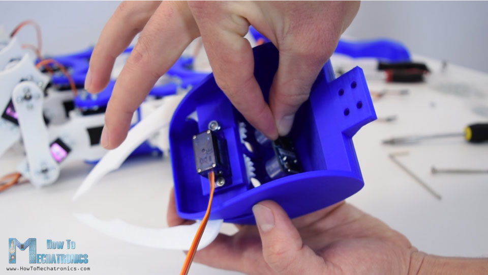
Before attaching the head to the mechanism we need to preassemble it, or attach the mandibles with the small SG90 servo and the ultrasonic sensor. Again it’s a bit tight here but I still managed to insert the first mandible and secure it to the head using a M4 bolt.
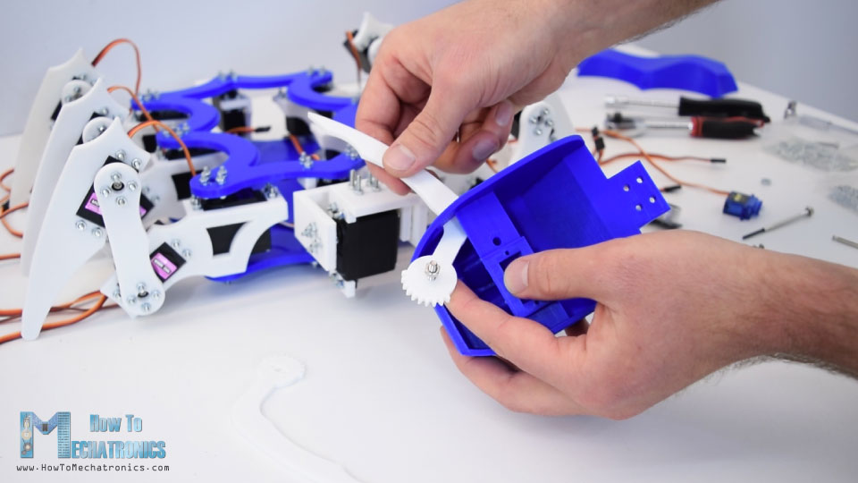
You can notice that there is a small hole at the eyes area which is specifically designed so we can pass through a screwdriver to tighten the bolt.
Next goes the micro servo in place and it is secured using two screws. On the second mandible we first need to attach a small arm horn for the SG90 servo.
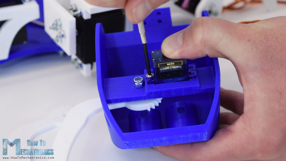
Then we can insert the mandible in place, pair the two gears and secure it to the motor shaft using a screwdriver.
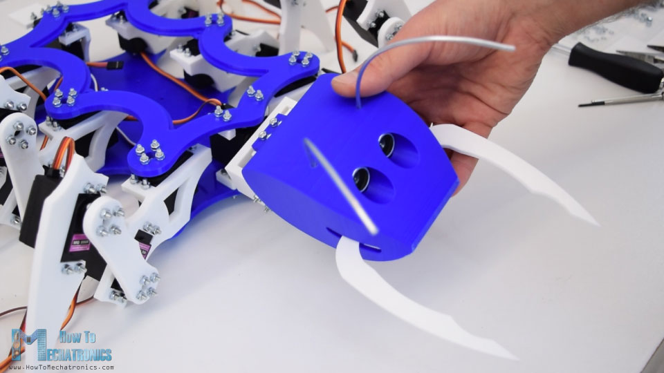
Next we can put the ultrasonic sensor in place. The eyes holes are made exactly to fit the ultrasonic sensor so I simply used few drops of AC glue to secure the sensor to the head.
There is one more detail to be added to the head and that’s the antennas. For that purpose I used 3mm tick wire, which I cut it around 13cm in length and I slightly bend it to get the desired shape. Again I used few drops of AC glue to secure them to the head. Finally we can attach the head to the roll and tilt mechanism with the four bolts we previously inserted.
The head is now fully functional, it can roll, it can tilt and even it can bite. There are two more 3D printed parts to be installed. That’s the tail which can simply slide into the tail bracket and the curved cover which we will actually use it at the end to cover up the electronics. So this is the final appearance of our ant robot and I really like how it turned out in this blue and white color combination.
Arduino Ant Robot Circuit Diagram
Ok, now we can move on with the electronics. Here’s the circuit diagram of this project which is actually simple although it looks a bit complex because of the many servos connections.
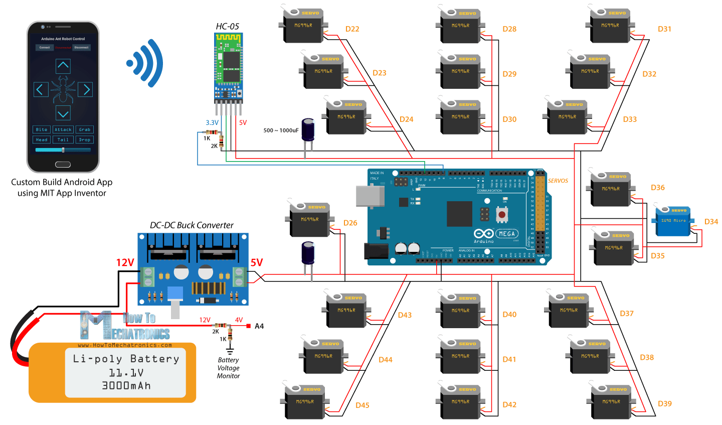
Besides the 22 servos we need an HC-05 Bluetooth module for the smartphone communication and some capacitors and resistors. Of course the brain of the robot is an Arduino board, and in this case that’s the Arduino Mega because it’s the only board that can control more than 12 servos using the Servo library.
Related Tutorial: How Servo Motors Work & How To Control Servos using Arduino
For powering the robot I will use a 3S LiPo battery which has a voltage of around 12V. LiPo batteries can handle higher amount of current draw, so they are suitable for this project because if all servos are engaged at the same time at full load they can draw around 10 amps of current. However, the servos operating voltage is limited from 4.8 to 7.2V, which means that I need to use a DC-DC buck converter to convert the 12V to 5V. Even in case we use 2S LiPo battery which has a voltage around 7.4V or 8.4V when fully loaded we still need to use a buck converter. The buck converter that I will use for this project can handle up to 8 amps of current but I would recommend to use one from 10 to 15A just to be sure you will have enough power and it won’t overheat. In my case, the maximum current draw that I noticed from the robot when moving was around 6 amp.
You can get the components needed for this project from the links below:
- MG996R Servo Motor……………………….…. Amazon / Banggood / AliExpress
- SG90 Micro Servo Motor ……..…….….……. Amazon / Banggood / AliExpress
- HC-05 Bluetooth Module ………………….… Amazon / Banggood / AliExpress
- Arduino Mega Board ……………………….…. Amazon / Banggood / AliExpress
- 3S LiPo Battery ………………………..……….. Amazon / Banggood / AliExpress
- DC-DC Buck Converter ………………………. Amazon / Banggood / AliExpress
Disclosure: These are affiliate links. As an Amazon Associate I earn from qualifying purchases.
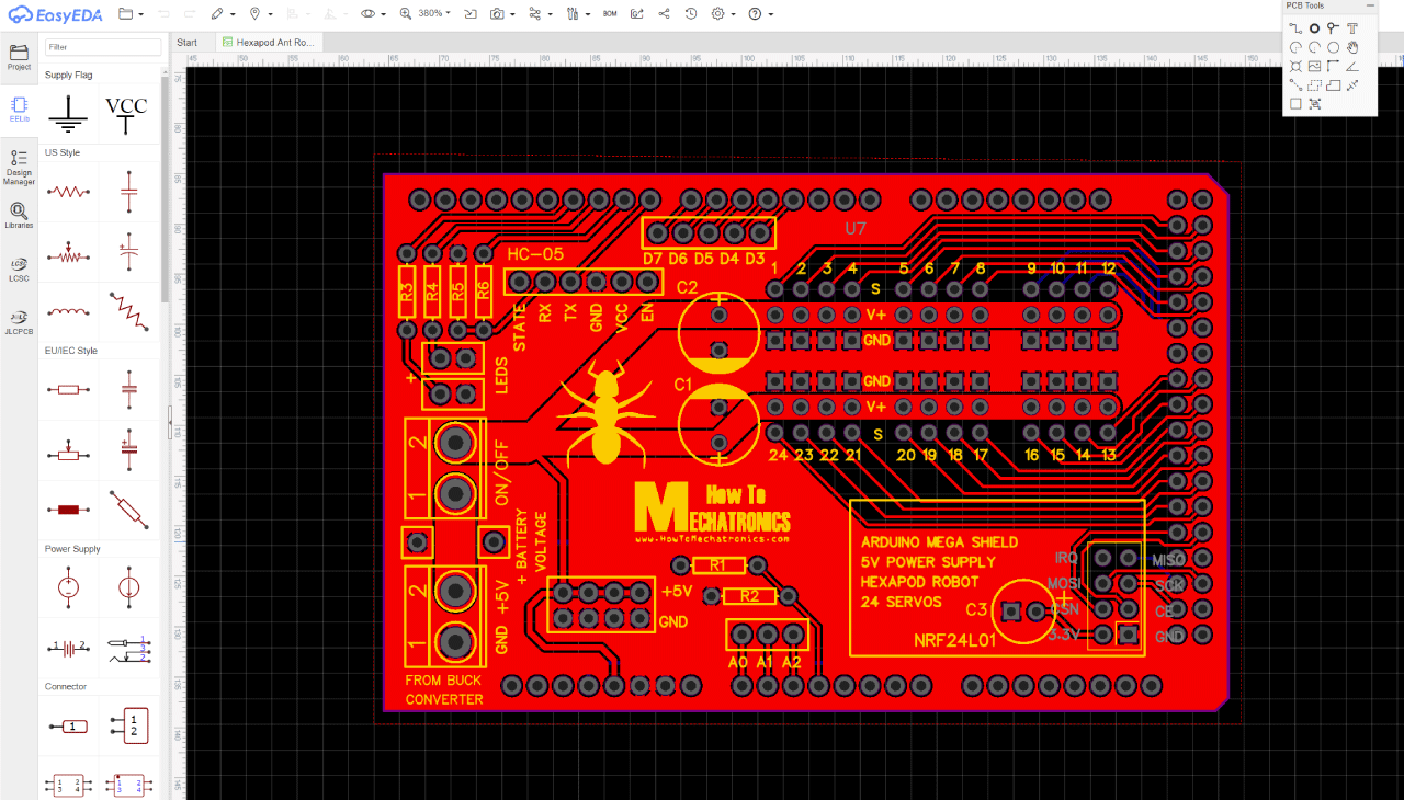
Designing a PCB for the Arduino Hexapod
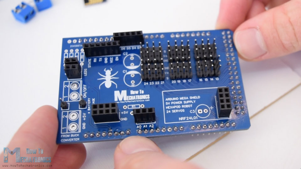
Now if we try connect everything together it will be quite a mess because of the many servo connections. Therefore I designed a custom PCB using the EasyEDA free online circuit design software. This PCB will be actually act as an Arduno Mega Shield for the Hexapod because we will be able to directly connect it on top of the the Arduino Mega Board. I arranged the servos connections close to each other and included two big capacitors next to them to keep the voltage more stable. Also I included a connection for a NRF24L01 transceiver module in case we want to control the robot using a radio control. There are several digital and analog pin connections, 5V and ground connections, two LED connections, as well as a connection for the monitoring the battery voltage. The 12V battery voltage will pass through a voltage divider made up of two resistor R1 and R2 which will reduce the voltage below 5V so that the analog pin can safely read it. In this way we will know when the battery will need to be recharged.
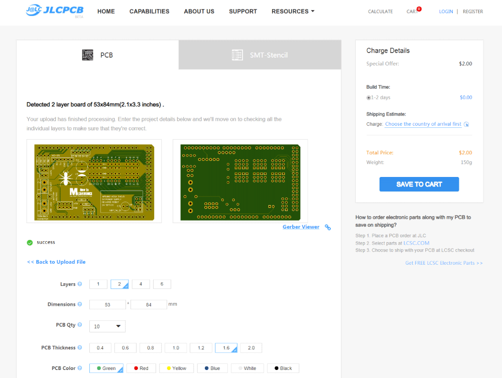
Here’s a link to the project files of this PCB design. So once I finished the design, I generated the Gerber file need for manufacturing the PCB.
Gerber file:
Then I ordered the PCB from JLCPCB which are actually the sponsor of this video.

Here we can simply drag and drop the Gerber file and once uploaded, we can review our PCB in the Gerber viewer. If everything is all right then we can go on and select the properties that we want for our PCB. In this case I chose the PCB color to be blue in order to match with the Arduino board color. And that’s it, now we can order simply our PCB at a reasonable price. Note that if it’s your first order from JLCPCB, you can get up to 10 PCBs for only $2.
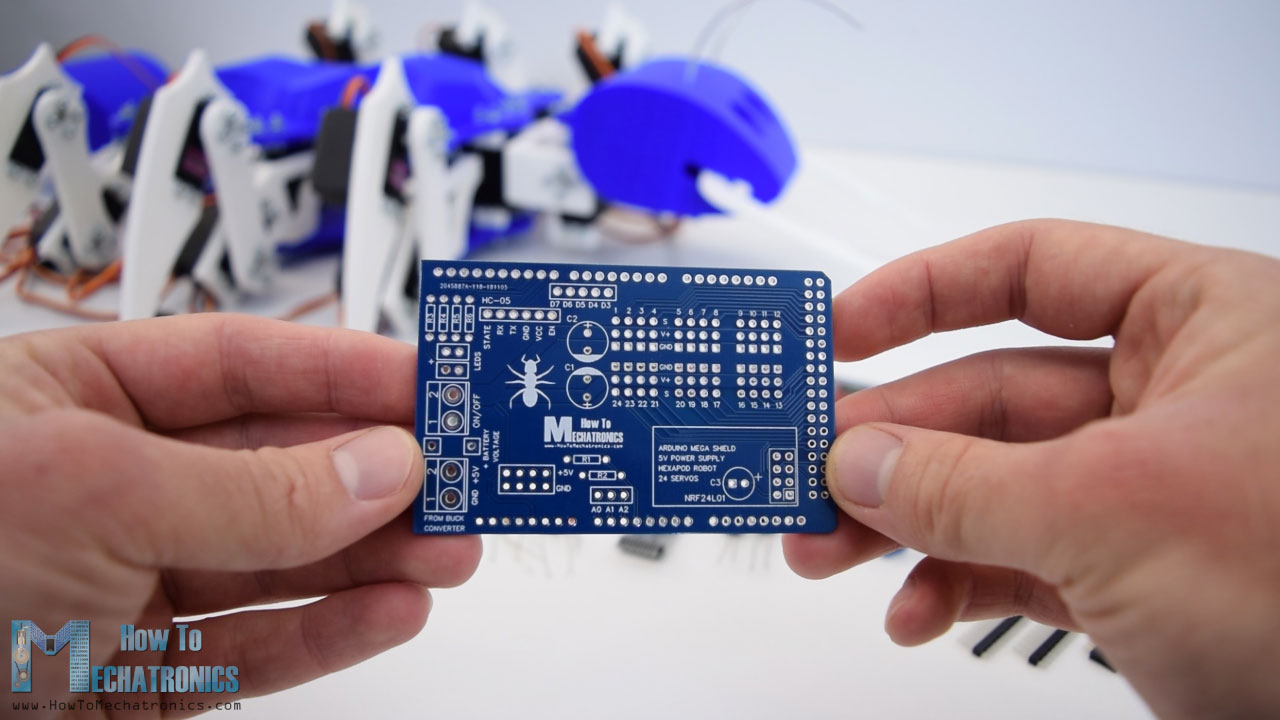
After several days the PCBs have arrived. The quality of the PCBs is great and everything is exactly the same as in the design.
Assembling the PCB
Ok, now we can move on and assemble the PCB. I started by soldering male pin headers to the PCB which are used connecting it to the Arduino board. Once we place the pin headers on the bottom side, we can use some kind plate hold the pins and flip the board. Now we need to solder all of them to the PCB. Once finished with that, we can move on with the servo connections for which we also need male pin headers.
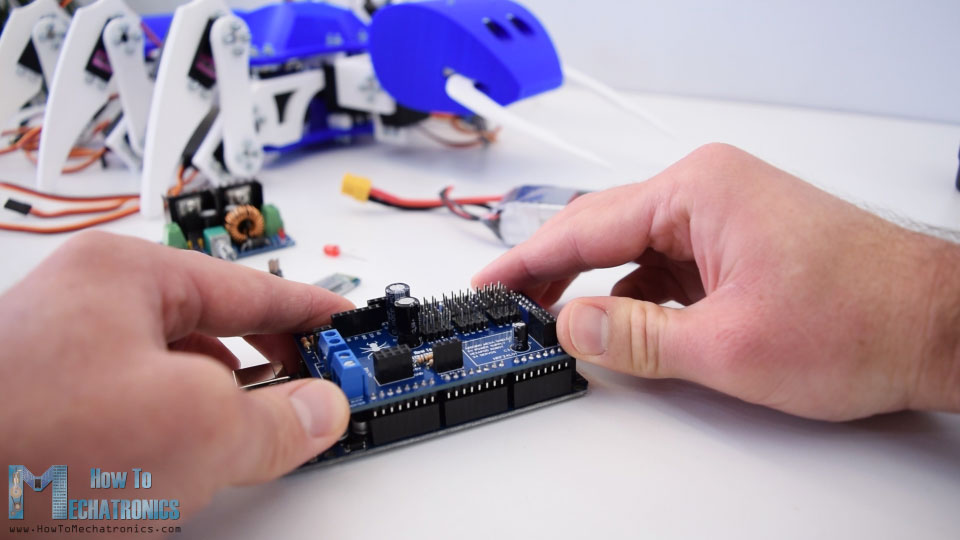
At this point we can actually insert the pin headers for all connections and use the same method to flip the PCB and solder all of the pins to it. At the end we need to solder the resistors, the capacitors and the terminal blocks. And that’s it, the Arduino Mega Shield for our Ant Robot is now ready. Now we can simply insert it onto the Arduino board.
Next we need to set the buck converter output voltage to 5V. We can do that by adjusting the potentiometer of the buck converter. You can notice here that I added a power switch to the input and connected the battery 12V to the 12V pin on the PCB which will be used only for monitoring the battery voltage.
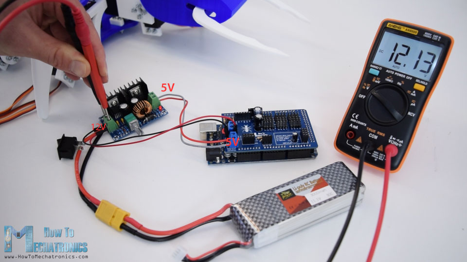
Remember that the main input to the PCB must be 5V.
So now we can insert the electronics components between the two plates. Again it’s a bit tight but still we can fit everything in. First goes the battery which I secured it using a tape, and on top of it goes the Arduino together with the PCB we made. Next we can connect the NRF24L01 transceiver or just the Bluetooth module depending on what type of communication we will use. I also inserted a LED for indicating when the battery needs to recharge, or in case the voltage drops below 11V volts. Lastly we need to connect all servos to the servo pins. While doing this make sure you write down to what pin number you connected each servo. After we connect all servos we can simply put the curved cover on the top plate and we are actually done with this project.
Arduino Hexapod Code
What’s left to do in this video is to take a look how the Arduino program works. As the code is a bit longer, for better understanding, I will post the source code of the program in sections with description for each section. And at the end of this article I will post the complete source code.
So for controlling the servos we will use the basic Servo library and for the Bluetooth communication we need to include the SoftwareSerial library as well. First we need to define all servo objects as well as some variables needed for the program below.
#include <Servo.h>
#include <SoftwareSerial.h>

#define trigPin 7
#define echoPin 6
#define ledB 10

SoftwareSerial Bluetooth(12, 9); // Arduino(RX, TX) - HC-05 Bluetooth (TX, RX)

// Create servo object
Servo s24;
Servo s23;
Servo s22;Code language: PHP (php)
In the setup section we need to initialize the Bluetooth communication, the pin modes for the ultrasonic sensor, the LEd and also define the pins to which the servos are connected.
void setup() {
  Serial.begin(38400);
  Bluetooth.begin(38400); // Default baud rate of the Bluetooth module
  Bluetooth.setTimeout(1);
  delay(20);
  pinMode(trigPin, OUTPUT); // Sets the trigPin as an Output
  pinMode(echoPin, INPUT); // Sets the echoPin as an Input
  pinMode(ledB, OUTPUT);
  // Head
  s15.attach(36, 600, 2400);
  s14.attach(35, 600, 2400);
  s13.attach(34, 600, 2400); //grip
  // Tail
  s5.attach(26, 600, 2400); // Tail
  // Leg 4
  s10.attach(31, 600, 2400);
  s11.attach(32, 600, 2400);
  s12.attach(33, 600, 2400); //rot
  // Leg 5
  s7.attach(28, 600, 2400);
  s8.attach(29, 600, 2400);
  s9.attach(30, 600, 2400); //rot
  // Leg 6
  s1.attach(22, 600, 2400);
  s2.attach(23, 600, 2400);
  s3.attach(24, 600, 2400); //rot
  // Leg 1
  s18.attach(39, 600, 2400);
  s17.attach(38, 600, 2400);
  s16.attach(37, 600, 2400); //rot
  // Leg 2
  s21.attach(42, 600, 2400);
  s20.attach(41, 600, 2400);
  s19.attach(40, 600, 2400); //rot
  // Leg 3
  s24.attach(45, 600, 2400);
  s23.attach(44, 600, 2400);
  s22.attach(43, 600, 2400); //rotCode language: JavaScript (javascript)
Then using the write() functions we move the servos to their initial position. Here’s actually where we can calibrate our servos. Consider that you won’t be able to set each servo at the exact position when assembling the robot, but here we can do adjustments and find out our initial values and from there we can program the robot movement.
// == Move to initial position
  // Head
  s15.write(72);
  s14.write(50);
  s13.write(90); // Grip

  s5.write(65); // Tail

  // Leg 4
  s10.write(65);
  s11.write(35);
  s12.write(40);
  // Leg 5
  s7.write(80);
  s8.write(50);
  s9.write(25);
  // Leg 6
  s1.write(90);
  s2.write(45);
  s3.write(60);

  // Leg 1
  s18.write(60);
  s17.write(90);
  s16.write(100);
  // Leg 2
  s21.write(50);
  s20.write(85);
  s19.write(75);
  // Leg 3
  s24.write(50);
  s23.write(80);
  s22.write(80);Code language: JavaScript (javascript)
When it comes to programing a hexapod movement there are several ways that to be done, like using a forward or inverse kinematics. These methods include some serious mathematics where the position of each joint is calculated based on the inputs for the desired final position of the body. However, I decided to make it a bit less complicated because anyway the servos that I am using are not good enough for such a task. That’s because my servos are the cheap version of the MG996R servo. They don’t have the right torque and they don’t always position at the exact desired position.
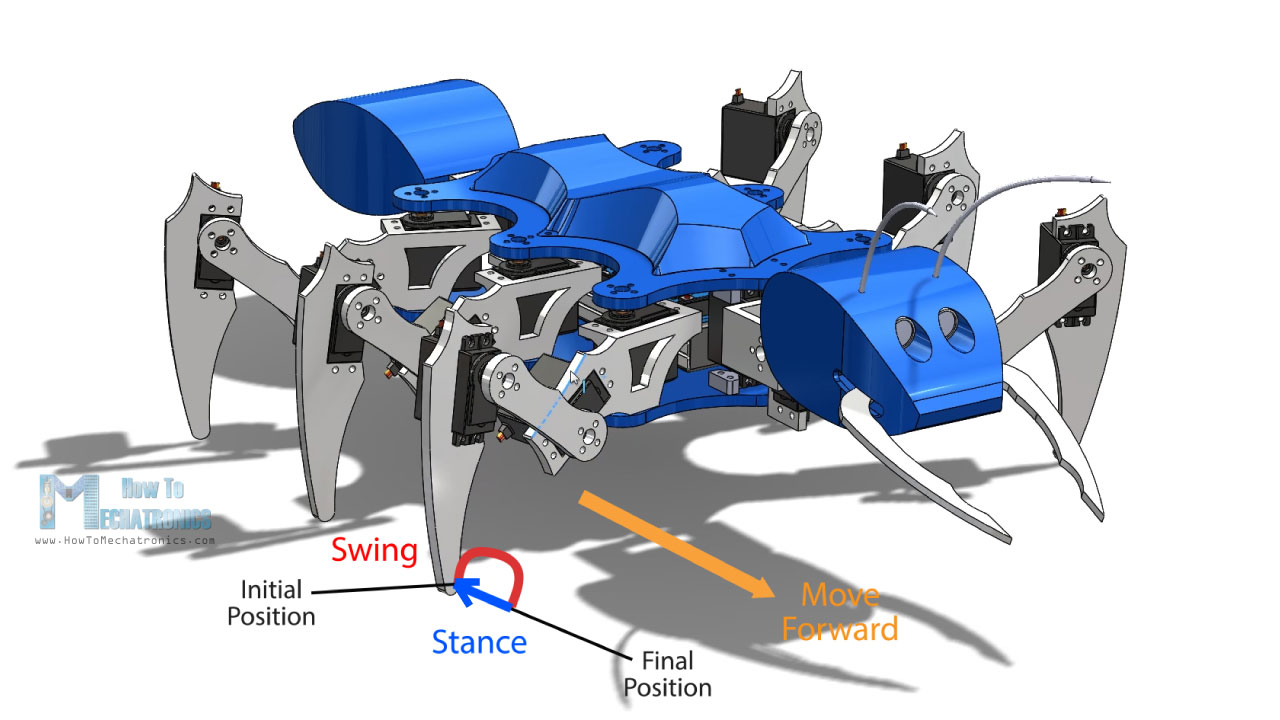
So let’s take a look how I made the hexapod walk. I made a separate custom function for moving each leg. A leg cycle includes two phase, called swing and stance. In the swing phase the leg move from an initial position to a final position through air, while in the stance phase the leg move from the final position back to the initial position with the leg end effector touching the ground. In this way the body of the hexapod will move forward.
So I manually program the positions of each servos to achieve these movements using the main loop and some counters.
void moveLeg1() {
  // Swign phase - move leg though air - from initial to final position
  // Rise the leg
  if (i1L1 <= 10) {
    s18.write(60 - i1L1 * 2);
    s17.write(90 - i1L1 * 3);
    i1L1++;
  }
  // Rotate the leg
  if (i2L1 <= 30) {
    s16.write(100 - i2L1);
    i2L1++;

  }
  // Move back to touch the ground
  if (i2L1 > 20 & i3L1 <= 10) {
    s18.write(40 + i3L1 * 2);
    s17.write(60 + i3L1 * 3);
    i3L1++;
  }
  // Stance phase - move leg while touching the ground
  // Rotate back to initial position
  if (i2L1 >= 30) {
    s16.write(70 + i4L1);
    i4L1++;
    l1status = HIGH;
  }
  // Reset the counters for repeating the process
  if (i4L1 >= 30) {
    i1L1 = 0;
    i2L1 = 0;
    i3L1 = 0;
    i4L1 = 0;
    i5L1 = 0;
  }
  // Each iteration or step is executed in the main loop section where there is also a delay time for controlling the speed of movement
}Code language: JavaScript (javascript)
So first the two outer servos rise the leg and the third servo connected to the body starts to rotate in a particular direction. When third servo is 10 steps before it stops rotating, we start move the outer two servos to the back at the same position to touch the ground. This completes the swing phase, or the leg moved from its initial to the final position. Then we rotate back the third servo from the final to the initial position, and that completes the stance phase. After the leg executes one cycle, the counters are reset and the leg will repeat the cycle over and over again. Each iteration or step is executed in the main loop section where there is also a delay time which controls speed of servos. I made functions like this for all other legs, as well as some additional functions for moving the legs in opposite direction for achieving reverse, left and right movements. In similar way using counters for keeping track of the steps I programmed the rest of the functions, like moving the head, moving the tail, the mandibles and so on.
So for example if we want to move the robot forward, we need to call the six moveLeg() custom functions which will constantly repeat in the main loop.
// Move forward
  if (m == 2) {
    moveLeg1();
    moveLeg3();
    moveLeg5();
    if (l1status == HIGH) {
      moveLeg2();
      moveLeg4();
      moveLeg6();
    }
  }Code language: JavaScript (javascript)
You can notice that the 3 legs are offset, so when the leg number 1 3 and 5 are in swing phase the other three legs, 2, 4 and 6 are in stance phase. In case we want to move left we call the appropriate moveLeft() functions.
These commands are actually coming from the Bluetooth module or the custom-built Android application from our smartphone.
// Check for incoming data
  if (Bluetooth.available() > 0) {
    dataIn = Bluetooth.read();  // Read the dataCode language: JavaScript (javascript)
Arduino Ant Robot Android App
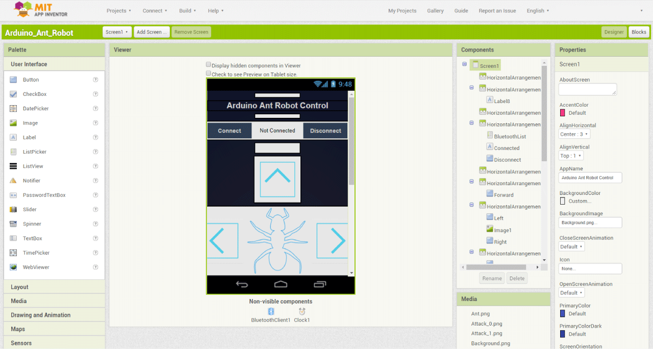
Let’s take a look at the app now and see what kind of data it is actually sending to the Arduino. I made the app using the MIT App Inventor online application and here’s how it works.
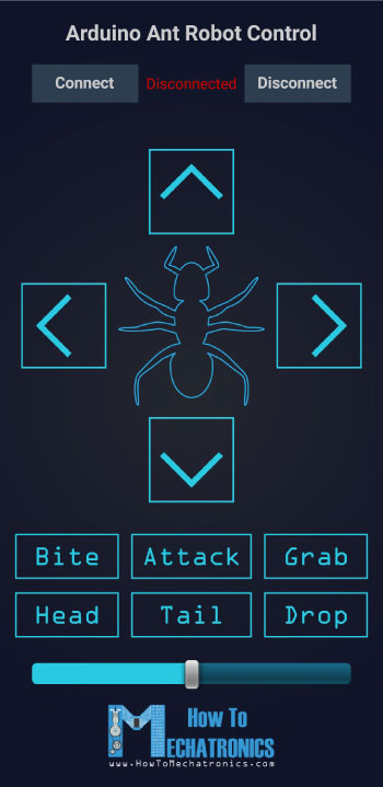
So the graphics of the app are actually images that I made and placed as buttons. At the bottom we have a slider for controlling the speed of the robot and at the top we have the buttons for connecting with the Bluetooth module.
Let’s take a look at the program or the blocks behind the app.
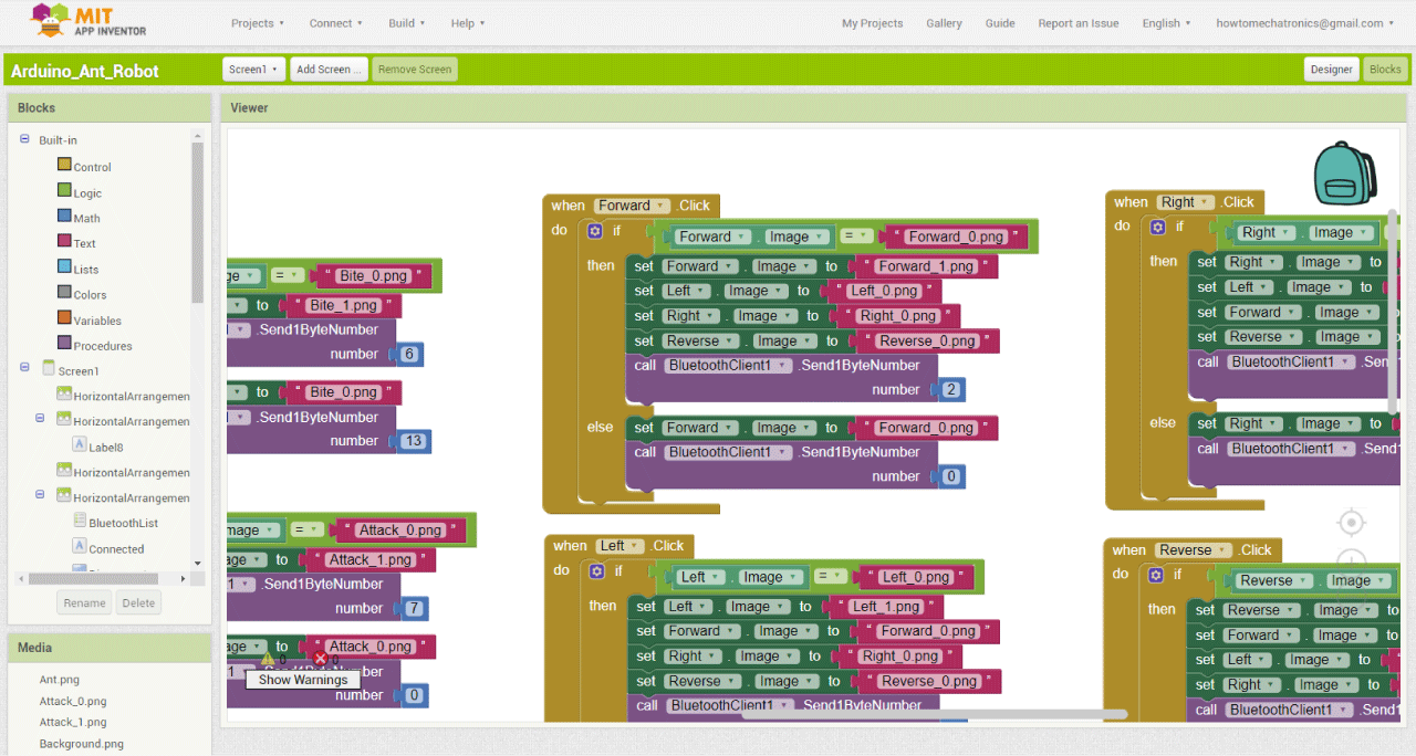
So for example if we click the Forward button, the blocks in the “if” statement will be executed. That means we will send the number 2 to the Arduino and that will execute the move forward set of functions. At the same time we can notice that we change the image of the button to the other highlighted version of the same image. If we press again the same button, now the blocks in the “else” statement will be executed and that will send the number 0 to the Arduino which will reset all counters and move the robot its initial positions. Also we set back the initial image of that button. So I used the same principle for all other buttons.
Here’s a download file of the above MIT App Inventor project, as well as the Android App ready to be installed on your smartphone:
Let’s just take a look at two more functions at the Arduino program and that’s the battery voltage monitor and ultrasonic sensor.
// Monitor the battery voltage
    int sensorValue = analogRead(A3);
    float voltage = sensorValue * (5.00 / 1023.00) * 2.9; // Convert the reading values from 5v to suitable 12V i
    Serial.println(voltage);
    // If voltage is below 11V turn on the LED
    if (voltage < 11) {
      digitalWrite(ledB, HIGH);
    }
    else {
      digitalWrite(ledB, LOW);
    }Code language: JavaScript (javascript)
So if the battery voltage is lower than 11 volts we will turn on the LED and if the ultrasonic sensor detects an object closer than 40 cm, the robot will prepare for an attack.
// Get the distance from the ultrasonic sensor
    if (getDistance() > 40) {
      att = 0;
    }
    if (getDistance() <= 40) {
      att = 1;
      dataIn = 99;
    }Code language: JavaScript (javascript)
In case the there is no longer object in front it will dismiss the attack and if the object is still present and closer to the head the robot will attack.
// If there is an object in front of the sensor prepare for attack
  if (att == 1) {
    prepareAttack();
    if (aStatus == HIGH) {
      while (a == 0) {
        delay(2000);
        a = 1;
      }
      if (getDistance() > 30) {
        att = 2;
        a = 0;
        aStatus = LOW;
        initialPosHead();
      }
      if (getDistance() < 30) {
        att = 3;
        a = 0;
        aStatus = LOW;
        initialPosHead();
      }
    }
  }
  // If there is no longer object in front, dismiss the attack
  if (att == 2) {
    dismissAttack();
    if (aStatus == HIGH) {
      dataIn = 0;
      att = 0;
    }
  }
  // If there is closer to the sensor attack
  if (att == 3) {
    attack();
    if (attStatus == HIGH) {
      while (aa == 0) {
        delay(2000);
        aa = 1;
      } attStatus = LOW;
    }
    if (aStatus == HIGH) {
      while (a == 0) {
        delay(2000);
        a = 1;
      }
      dataIn = 0;
      att = 0;
      initialPosHead();
    }
  }Code language: HTML, XML (xml)
So that’s pretty much everything for this video.
Here you can download the complete code for this Arduino Hexapod project:
Note that if you decide to build this project, you need to be prepared to face some challenges. The biggest problem for me was the poor performance of the servos that I used. I hope you enjoyed this video and learned something new. Feel free to ask any question in the comments section below and check my Arduino Projects Collection.
I just came across this wonderful project. What is the licensing on your designs, (model, PCB, code)?
Hi. Nice Project. I am motivated to make my version of hexapod, so i wanted to learn your code, but i can’t download it. Page says – Invalid File Type (*.ino)! How to fix this problem ?
Hey, I have updated the code download file, it should work now, please try again.
very nice to build it, for my little son, 3 years old
i do the same tools chooses, arduino, fusion 360, cura, mit inventor
i have only an ender 3, so i cut the big parts to print them
thank you, your projects are very detailled and interesting
Hello Dejan,
I finised the build and now want to connect the servos … Can you help me out which one goes where on the pcb board. ?
Thanks
can someone help me out with the servo pins ?
i have made a batterybox and brackets for the converter to share ….
thanks
dejan can u please help me out where to connect the servo’s to on your designed pcb board ?
thanks
and on which block is the ultrasonic sensor attached ?
C1 and C2 i found in earlier posts .. 200-50 uF but what do i need for C3
Anything between 10uF to 100uF with voltage rating around 16V to 63V.
Do you have a schematic for how to connect the servos etc too the pcb board you designed ?… i found the scheme without it but its a bit hard to get and what goes where on the pcb board…
HI , i am currently printing the parts for this wonderfull ant:
but can you please make a parts list:
-like which bolts and nuts to use: flathead, philips screw , lock nuts , washers etc?
-like which parts needed to solder on the board
-which metal servo horns you use and use only them or need to use the plastic ones also?
Hey, most of the bolts used in this project are flathead M3 bolts with around 12 or 14mm length, you would need around 200 of them, also washers and nuts, or you could go with just lock nuts without washers. You will also need 15 M4 bolts and nuts and washers.
The parts you need to solder to the board are the capacitors, the resistors, the terminal blocks, and the pin headers.
As for the horns, you can use any of them, either plastic or metal, it doesn’t matter. I think I didn’t have enough plastic so I used metal horns as well which can be separately bought.
thanks dejan,
can you please tell me which capacitors i need ???
for the C1 C2 and C3….
i orderd your great board and am now soldering everything on….
Sir I guess the link for the app isn’t working because the download isn’t proceeding when I click on download
Sir please reply if I can use a 3000mah power bank with 5v output instead of using lipi battery and a converter
I don’t think so, because the power bank won’t be able to handle the amount of current the robot will draw, which is around from 5A to 10A at peak.
Hi Dejan, this project is really impressive, thank you very much for sharing it in such details. I’m trying to replicate it with my ten years old son! I think he’ll enjoy 😉
Hey, thanks, I’m glad to hear that! Have fun building, but bare in mind that it’s not that easy to do project. Be prepared to do a lot of troubleshooting. 🙂
This project is really incredible … I am trying to replicate it, my problem is that at the time of assembling the ant (after calibrating the servos with the code), it starts to shake or does not move, could you please tell me which servos are connected in the respective numbers of the PCB example: servo 34 (in the diagram) pin 10 servo 49 pin 22 please, I have little time to present the project, and I have bought and cast everything in the image and likeness of your video
Hey, thanks! Well you can trace lines of the servo connections and see at what pins they are connected on the Arduino Mega. Make sure you power supply can handle the current draw of all servos, you may need up to 10A or 15A rated power supply (5V).
hello,
did you find out which pins you needed on the pcb board ? and to which servo it goes? i am struggeling with it too…
if you know, help me out please….
thanks
Martijn van den Brakel
Hi, thank you for listing the bolts/nuts. I believe I’ve purchased all of them; for the M4 bolts, I chose the hex head type, because I had to guess from what looks like from some of your pictures. I also purchased a 200 set containing 200 M3 bolts + nuts + plain washers. I also purchased some 200 spring washers for securing the M3 bolts and 25 metal round servo arms with M3 threads.
Now I’ve got a question which concerns me: I also went along and purchased a 7.4V 3500mAh (2S) LiPO, and now I am trying to figure out how to modify your code in order for it to read the ADC values correctly for the 7.4V input.
I suppose there’s no need to change the resistor values for the voltage divider, provided you change the “2.9” constant value in line:
[code]
float voltage = sensorValue * (5.00 / 1023.00) * 2.9; // Convert the reading values from 5v to suitable 12V i
[/code]
But I can’t figure out how you came up with it, care to give a little more explanation on this matter? Thanks.
Well yeah, you don’t have to change the resistors values. You actually don’t have to change even the “2.9” constant I think. Just use the serial monitor to see what value you are getting, measure the real voltage of the battery and if needed adjust the “2.9” constant.
Hi, could you kindly list all the screws and nuts used in this project?
I assume all are M3, diameter?
But even so, there are some different lengths and some different nuts, as well as there are washers in the legs and other spots – I’m not too familiar with mechanics so that would help me to sort out the shopping for those.
Thank you.
Hey, I used M3 bolts with 14mm of length, but 12mm length can also be used. You need around 180 of these, bolts and nuts, and washers as well if you are not using self locking nuts. You will also need like 10-15 M4 bolts with length of around 16 to 20mm.
Hello,
I’m starting to assemble this great project – but how do you set the servos to the “idle” position at the begining of the assembly?
My idea was to start the arduino and plug every servo on its position to move it to the default position. What was your way? Do you have a better idea?
Hey, well yes, that way you can attach and secure the servos in correct position without adjusting the code. To be honest, it’s a bit tricky and the code is not the best, but hopefully you will sort things out.
Hello, I got a PCB of your Mega Servo Shields . Unfortunately, I find no values for R1 to R6 and for C1 to C3. Could you tell me the required values?
Hey, here are the values of the resistors and the capacitors.
R1=2K, R2=1K, R3=R4=220, R5=1K, R6=2K.
C1=C2 ~ 200 – 500uF
If we use SG90 instead of MG996R, what will be the changes for coding?
The coding would be the same, as the SG90 and the MG996R work the same way. However, you wouldn’t be able to use this model, but a completely different one as the SG90 is a lot smaller servo than this. And also I would’t recommend making a project like this with SG90 servos, they just don’t have enough torque.
Thank you for the tutorial. It looks great, very professional. You have a lot o different skills. 3D printing, designing your own circuit board, programming, designing in SolidWorks… It is a complete engineering project from start to finish. 🙂
At the end of the video, you said that the biggest problem for you was the poor performance of the servos that you used. Can I ask what the problem(s) were and what you did to resolve them?
Thank you! Well the problem was that the servo didn’t have the proper torque, and they were a bit jerky, didn’t stay in the exact position under the load of the hexapod. I actually didn’t solve this problem. Using different high quality servos would probably solve that problem, but then it comes another problem, the total cost of the project would rise significantly because there are so many servos.
Awesome! I don’t know how to say, but.. you are the best. thank’s for sharing this awesome project, thank you, thank you
Thank you!
Hi
Great project. I see you haven’t used any servo controller. Arduino Mega has 15 PWM pins so how are you able to run 21 servos using one Arduino Mega?
As far as I know servo motors need PWM pins. In code, you have not used pwm pins.
Hey, thanks! Well I’m using the Servo library which doesn’t use the PWM pins, it generates special 50Hz PWM signals and it can be used with any digital pin.
This is very impressive! What will you do with it?
Have you considered using it for teaching STEM to kids?
Thank you! Well I hope I teach many kids through these website and the YouTube channel. 🙂
very impressive, I am admiring, what a job!
Thank you!
Which software you had used for 3d modeling?
I used Solidworks for the 3D modeling.
Your Arduino projects all wonderful. Can you teach us something about solidworks for the 3D modeling. I thinke it very interesting as the arduino projects.
Thank you! Well currently I don’t have Solidworks tutorials, but maybe I will make some in future.