In this tutorial we will learn how to build an Arduino based RC Hovercraft. I will show you the entire process of building it, starting from designing and 3D printing the hovercraft parts, including the propellers, to connecting the electronics components and programming the Arduino.
You can watch the following video or read the written tutorial below.
Overview
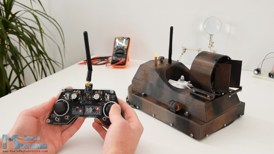
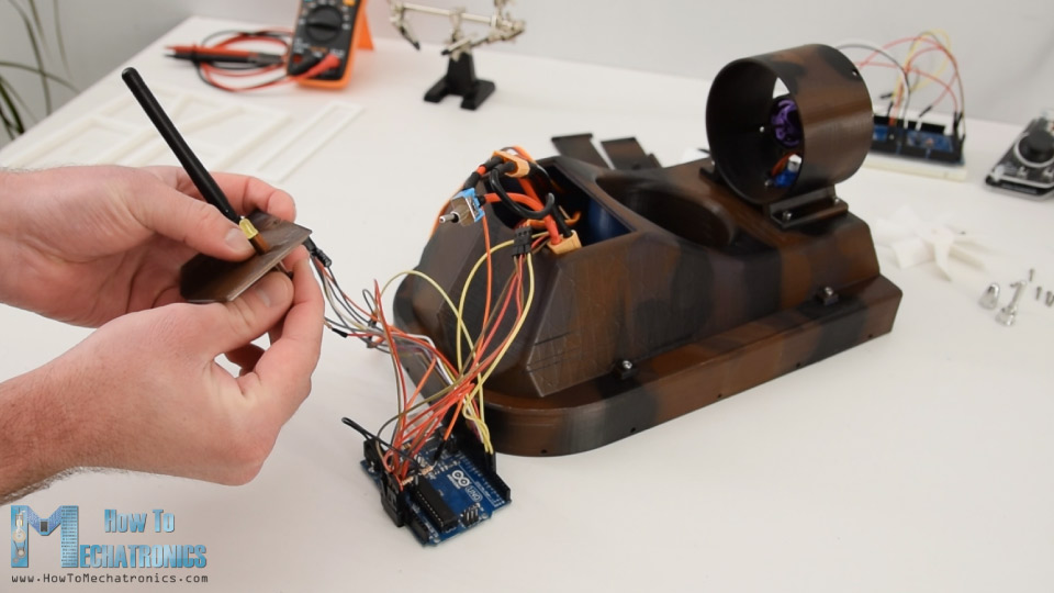
For controlling the hovercraft, I used my DIY Arduino based RC Transmitter which I made in one of my previous videos. I set the right joystick to control the servo motor for positioning the rudders on the back side of the thrust motor, set one of the potentiometers to control the lift propeller which is actually attached on a brushless DC motor, and set the left joystick to control the propulsion. So, let’s take a look what it takes to build this RC hovercraft.
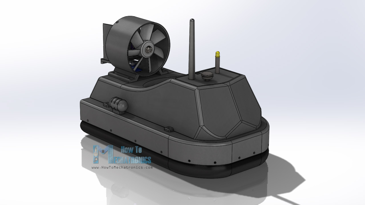
Hovercraft 3D Model
To begin with, I designed the hovercraft using a 3D modeling software.
You can find and download this 3D model, as well as explore it in your browser on Thangs.
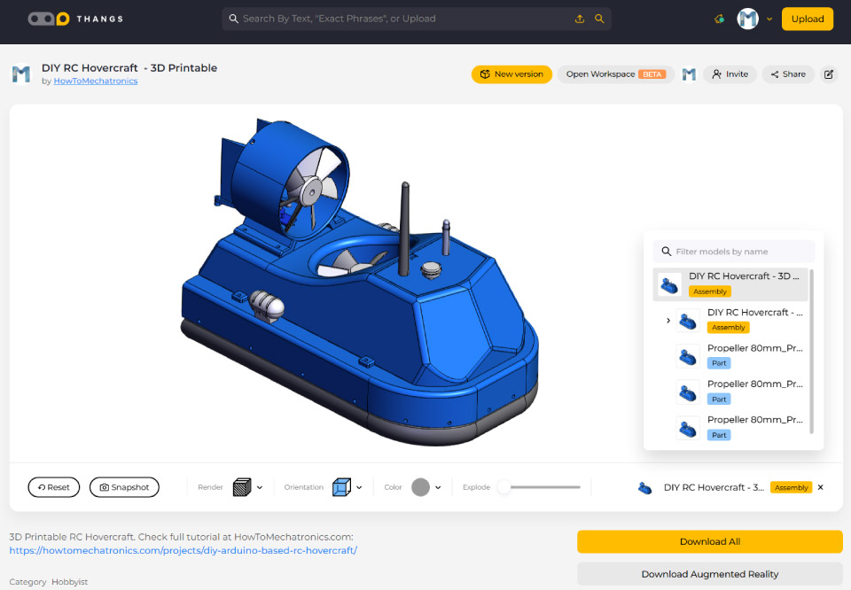
Download the assembly 3D model at Thangs.
STL files for 3D Printing:
See Also
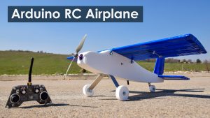
Arduino RC Airplane | 100% DIY
Hovercraft Working Principle
The basis working principle of a hovercraft is that the craft is lifted by a cushion of air. The central propeller blows air into underneath the craft, which inflates a skirt made out of soft material.
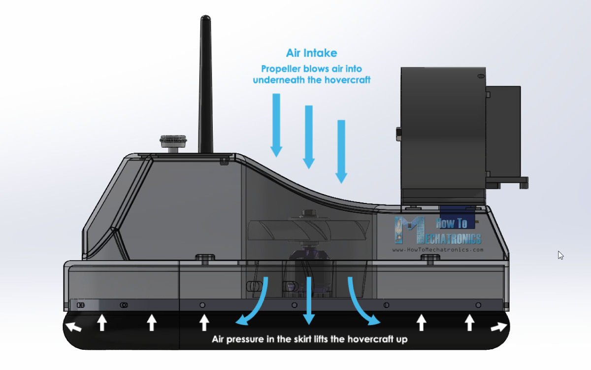
When the air pressure in the skirt is high enough, the craft gets lifted. The constantly supplied air escapes from the middle of the craft, between the skirt and the ground, which creates additional lift and also reduces the friction between the hovercraft and the ground.
Once lifted, using the second propeller a thrust is generated which moves the hovercraft forward.
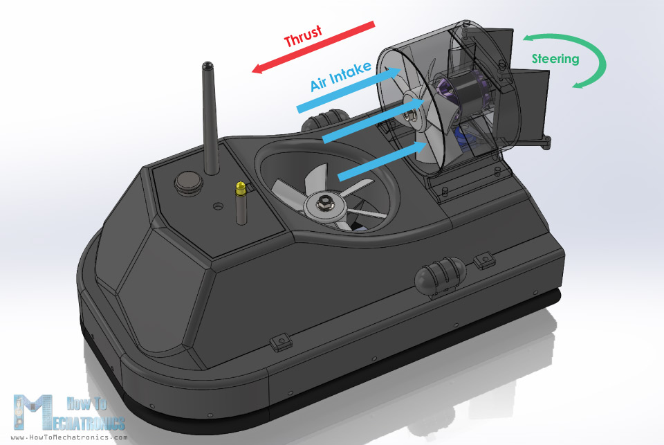
On the back side of the thrust propeller there is a simply set of rudders which are utilized for steering the hovercraft.
3D Printing
Nevertheless, once I finished the design, I started with 3D printing the parts.
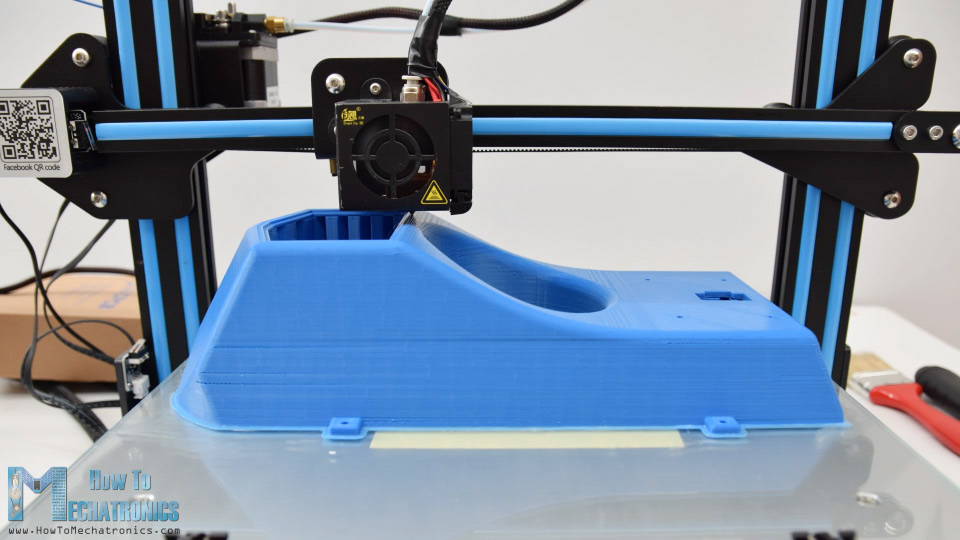
The hull of the hovercraft is the biggest part to print and I specifically designed to fit my Creality CR-10 3D printer, which has a print bed of 30x30cm.
Here’s a link to this 3D printer in case you want to check it out.
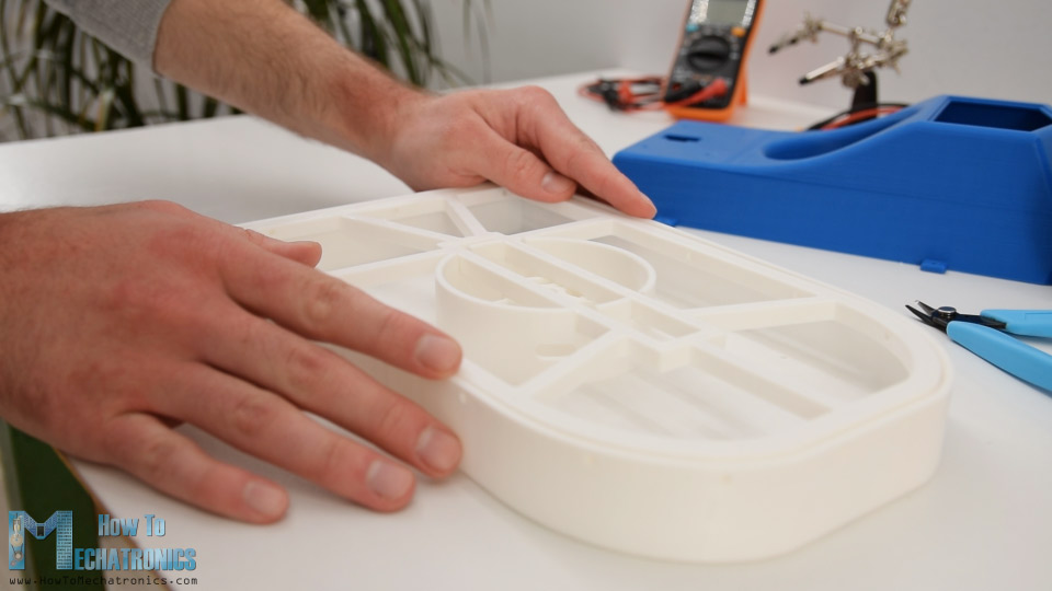
After the printing is done, it’s time to do some clean up. The main body of the hovercraft or the cockpit was the longest print which took around 18 hours to print. Because of the curved design, and because I wanted to be a single print, there was a lot of support material used for this print.
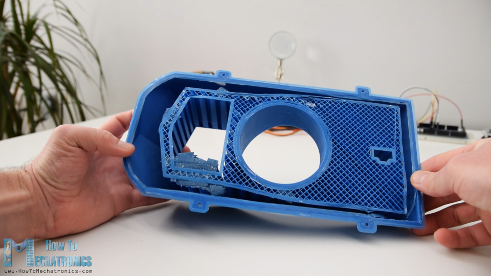
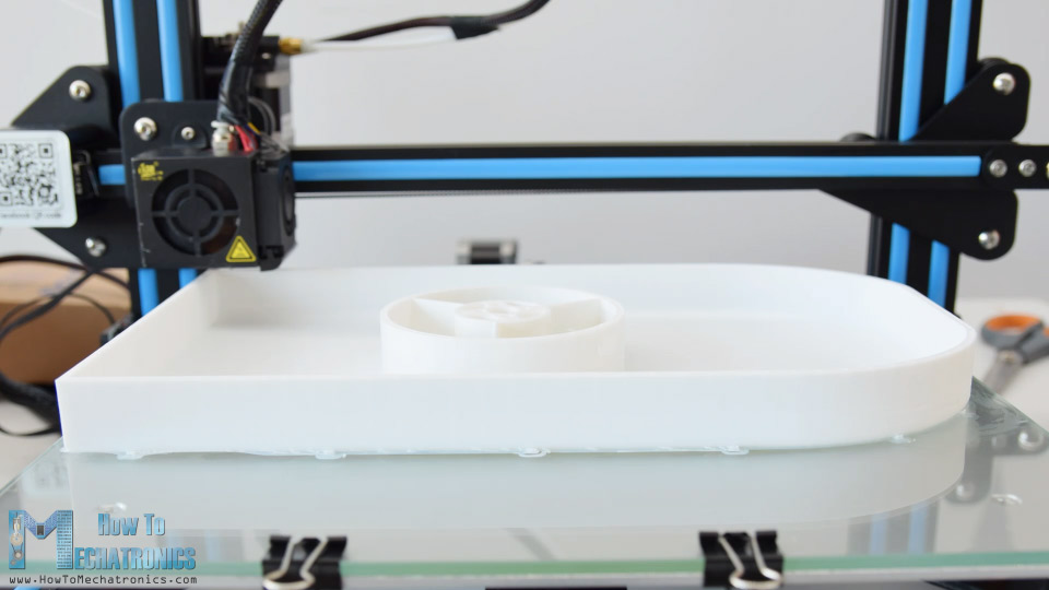
However, it was really easy to remove it and the final piece turned out just perfect. The hull of the hovercraft was printed upside-down and it had just a minor amount of support material to be removed. Actually, I had to make some adjustments to this print and cut some material out of the central blower housing so that the skirt holder can fit in properly.
I already updated the 3D model so won’t have this problem.
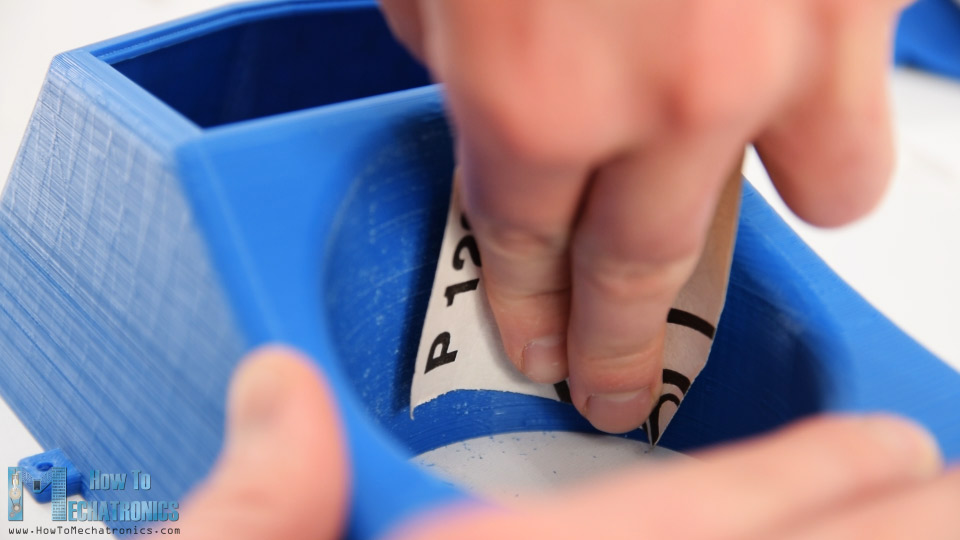
Some of the round areas of the parts were a bit rough so I used a simple sending paper to smooth them out.
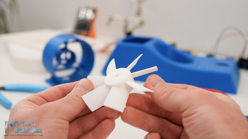
The propellers didn’t need any clean up and they worked quite good coming straight out of the 3D printer.
Painting the hovercraft
Ok the next step is painting the 3D printed parts. I didn’t use any primer before but directly applied an acrylic paint in a form of a spray paint.
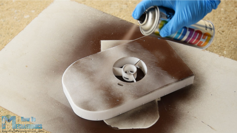
I used a chocolate brow color for the first coat. For some of the smaller parts, which are actually just decorating parts I used a lighter brown color.
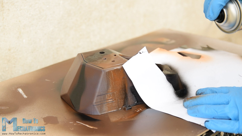
In order to make the hovercraft look a bit cooler, once the first coat dried out, I continued with adding two more colors to the parts. For that purpose, I made some random patterns on a simple sheet of paper, and used them to make stripes and spots in different colors. I used lighter brown and black color for that purpose.
Assembling the Arduino RC Hovercraft
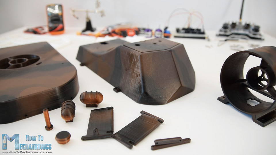
I really like how parts turned out, so once they dried out, I continued with assembling them.
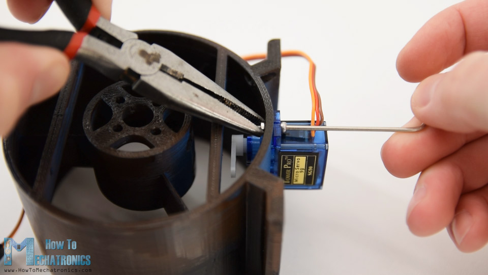
I started with installing the servo motor which controls the rudders onto the thrust blower housing. I secured the servo using two M2 bolts and nuts.
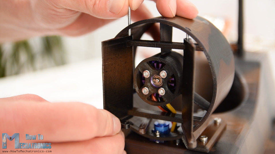
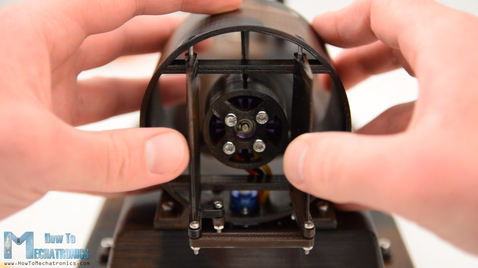
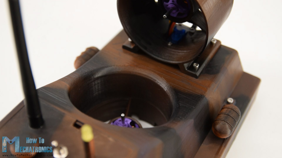
Next is the brushless motor. The particular model that I have is the D2830 which has a diameter of 28mm and 30mm of length, and of course, the housing is specifically designed to fit this motor.
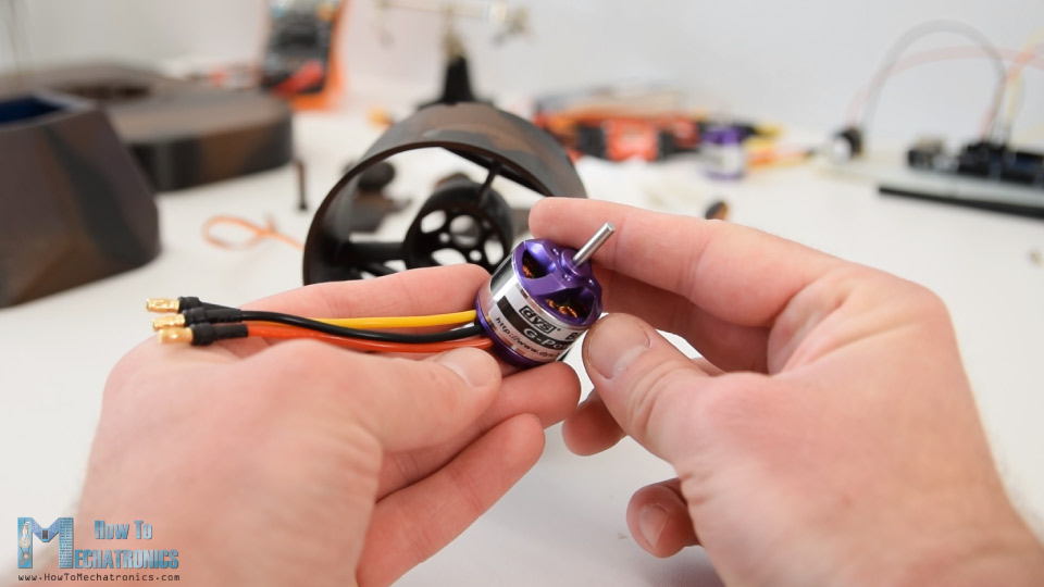
Here when inserting the motor, first I had to pass the wires through the openings. It’s a bit a tight, but still manageable to pass them through. Then on the back side, using M3 bolts I secured the motor to the housing.
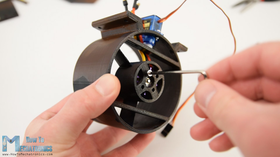
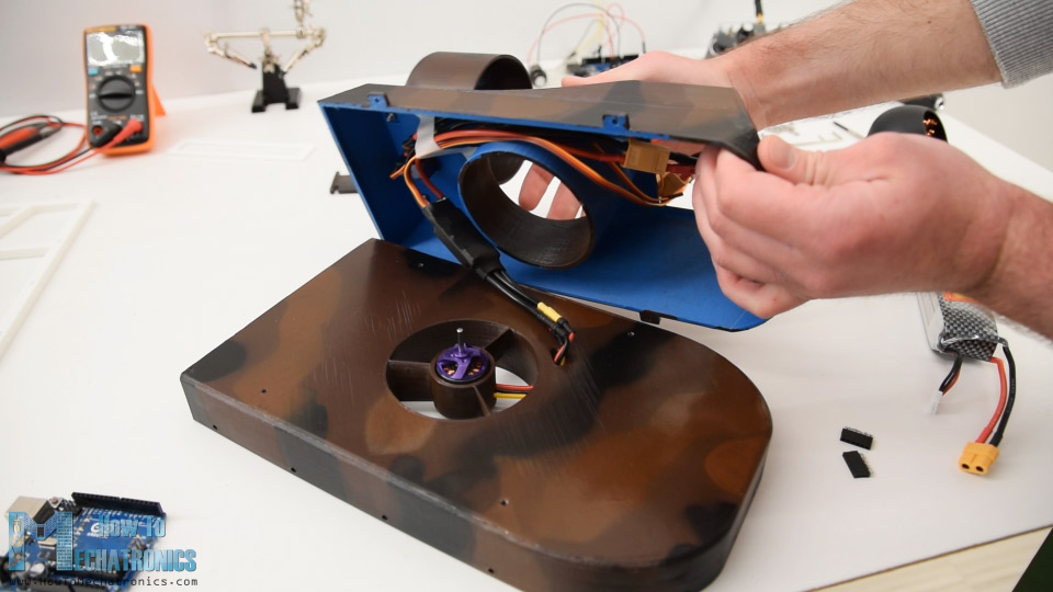
Next, I can merge the thrust housing with the main body of the hovercraft. This part has an opening so the servo and the BLDC motor wires can pass through.
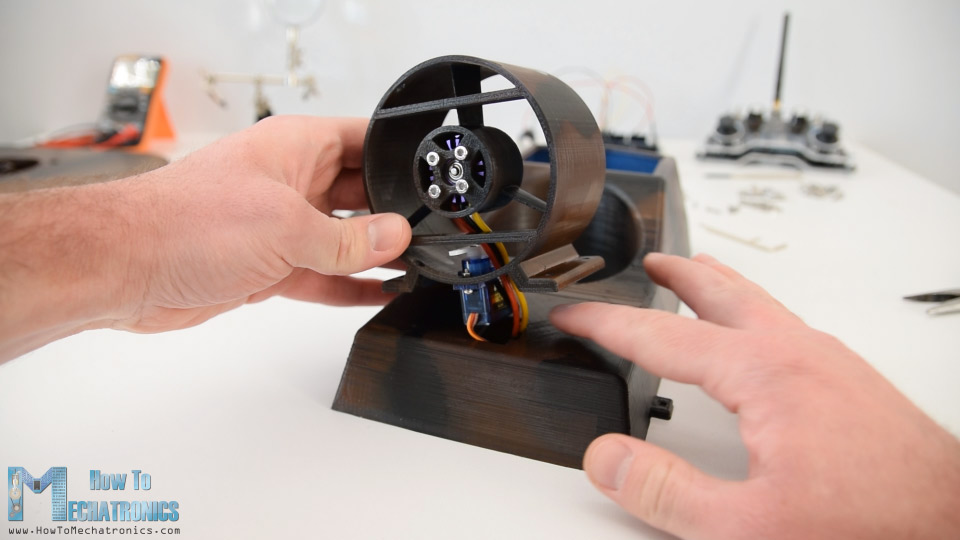
Using four M3 bolts, I secured them firmly together.
Once I finished that, I continued with installing the second brushless motor to the hull of the hovercraft. Here again I used the same method. First, I passed the wires through the openings and then on the back side secured the motor using four M3 bolts.
Circuit Diagram
Next comes the electronics. The electronic components will be placed in-between the hull and the main body of the hovercraft. But before we do that let’s take a look at the circuit diagram and see how everything needs to be connected.
So, the brain of this hovercraft is an Arduino board. With the Arduino we can easily control the servo as well as the two brushless motors using the two electronic speed controllers or ESCs. For powering the BLDC motors, I will use 3S Li-Po battery which provides around 11V, and for powering the Arduino, we can use the regulated 5V which the ESCs provide through their Battery Eliminator Circuit feature.
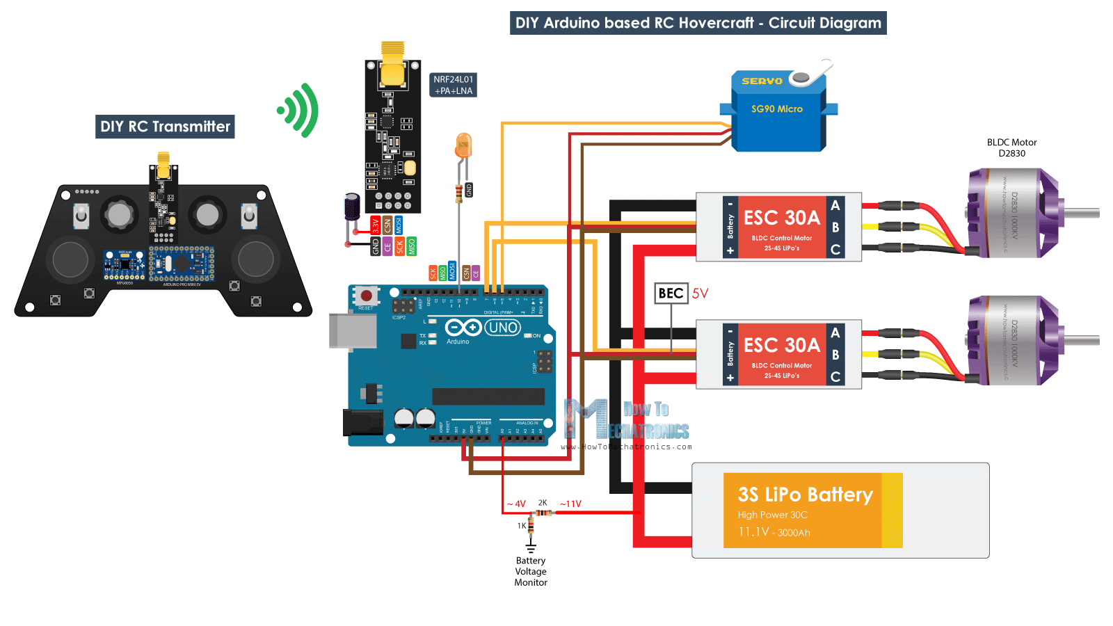
For the wireless communication I will use the NRF24L01 transceiver module which if used with an amplified antenna it can have a stable range of up to 700 meters in open space. The RC transmitter that I will use for controlling the hovercraft, is the one that I custom build in one of my previous tutorials, so you can check it out if case you need more details about it. There are also detailed tutorials on the NRF24l01 module, and how to use brushless motors using Arduino. Nevertheless, the basic working principle is that the transmitter sends the Joysticks or potentiometers data to the receiver which controls the speed of the brushless motors and the position of the servo.
There is one more small detail on this circuit diagram, and that’s the battery monitor. I added a simple voltage divider made out of two resistors, which is connected directly to the battery, and its output goes to the analog input of the Arduino. The voltage divider drops the 11 volts to around 4 volts which are then acceptable by the 5V Arduino pins. With this we can monitor the battery voltage, and set an LED to light up when, for example, the voltage of the battery will drop under 11 volts.
You can get the components needed for this Arduino Tutorial from the links below:
- NRF24L01 Transceiver Module…. Amazon / Banggood / AliExpress
- NRF24L01 + PA + LNA ………….…. Amazon / Banggood / AliExpress
- Brushless Motor ………………….…… Amazon / Banggood / AliExpress
- ESC 30A ……………………………….….. Amazon / Banggood / AliExpress
- Li-Po battery ……………………………….. Amazon / Banggood / AliExpress
- XT60 2 Female to 1 Male …………. Amazon / Banggood / AliExpress
- XT60 Connector ………………………… Amazon / Banggood / AliExpress
- Servo Motor ……………………………….. Amazon / Banggood / AliExpress
- Arduino Board ………………………… Amazon / Banggood / AliExpress
Disclosure: These are affiliate links. As an Amazon Associate I earn from qualifying purchases.
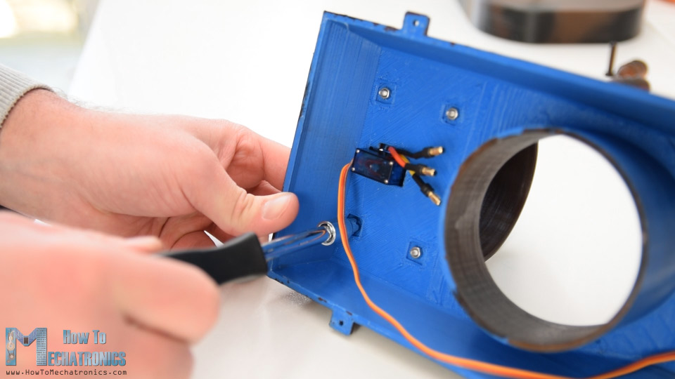
So, I started connecting the components as explained. For connecting the two ESCs to a single battery I used a parallel battery connector splitter, type XT60.
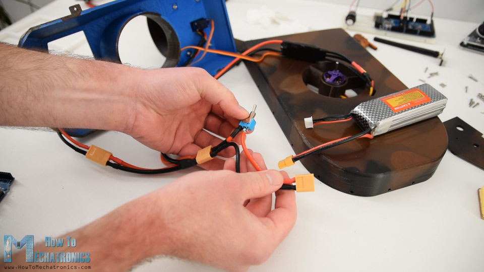
For adding a power switch to the project, I used another XT60 connector, on which I cut one wire and soldered a toggle switch there. So, one side goes to the Y splitter cable and the other side to the battery.
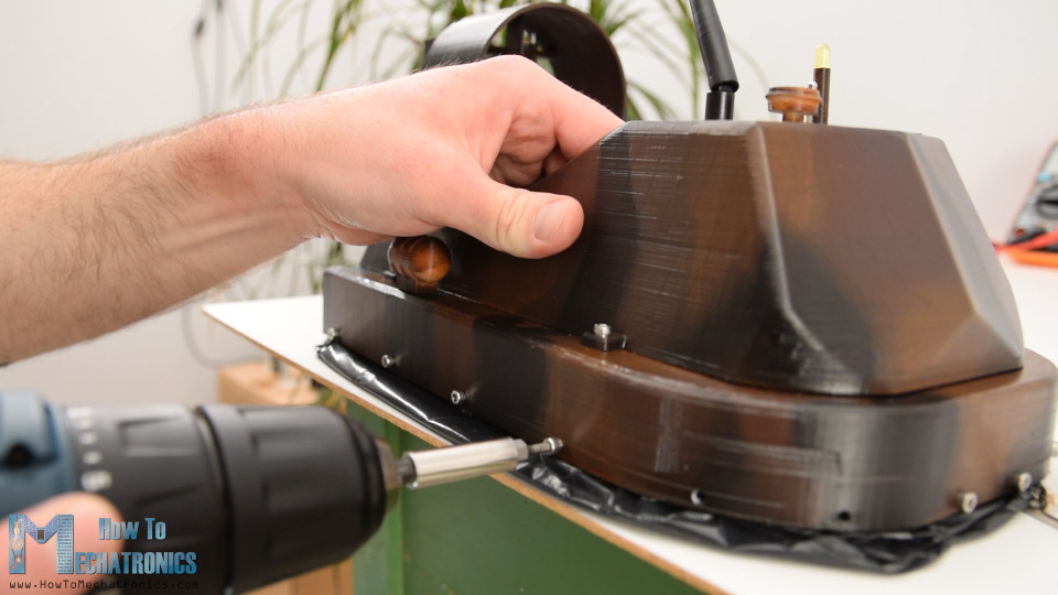
Next, I placed the ESCs into the main body and trapped them between it and the hull of the hovercraft. Then using four M3 bolts I fastened the two parts together. From the top opening of the body I then inserted the battery into the cockpit area.
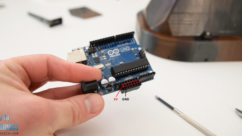
Next, we need to connect the components to the Arduino and for that purpose I added two pin headers to the Arduino which will serve as GND and 5V pins.
So, once I connected everything to the Arduino, I passed the NRF24L01 antenna, the indicator LED and the power switch, through the top cover of the cockpit.
Then I just needed to squeeze everything into the cockpit. It was a bit tight here because I used Arduino UNO, and probably I should have used and Arduino Nano instead.
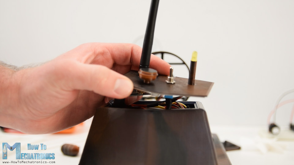
However, I managed to fit everything in, also attached a small decorating part to the cover and then just clipped it to the cockpit body.
I continued with installing the steering system. First, I connected a small link to the servo horn using a M2 bolt and a nut. Then I inserted the first rudder in place and secured it to the thrust housing using a 2mm metal wire which passes through its body and so the rudder can rotate around it. In the same way I attached the second rudder.
This rudder has an additional slot so we can connect it to the previously insert link to the servo. Again, I used M2 bolt and nut for securing them. And finally, I connected the two rudders to each other using another link and with that the steering system is completed.
Next, I will attach this small decorating part on the side of the hovercraft. Using a drill, I made a hole and then secured the part to the hull using a single screw. I placed these parts on both sides and I think they fit quite good to the overall appearance of the hovercraft.
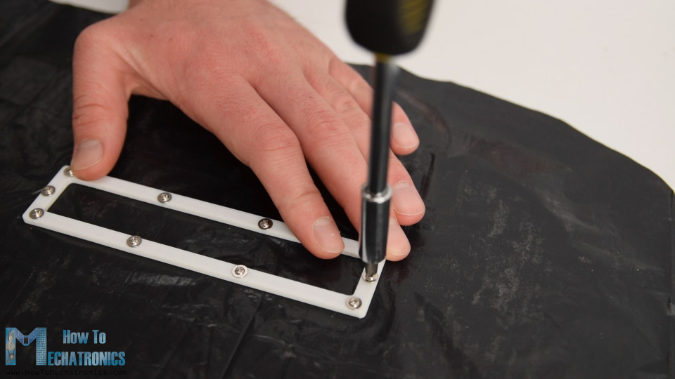
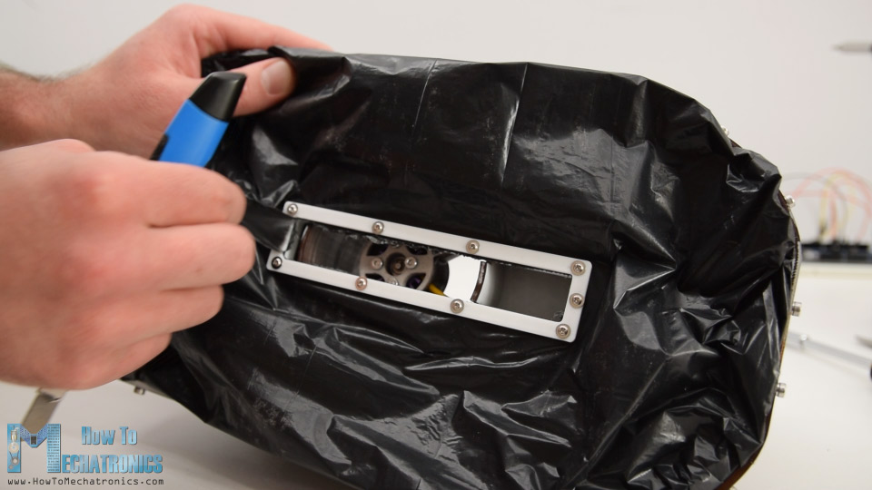
Ok, next I continued with making the skirt for this hovercraft. You can notice here the skirt holder has holes around it and that’s for attaching it to the hull.
There are also slots for nuts to be placed in and in that way, we will be able to easily secure the skirt holder to the hull using M3 bolts. Once I secured all the nuts in place, I continued with making the skirt for which I used a simple trash can plastic bag.
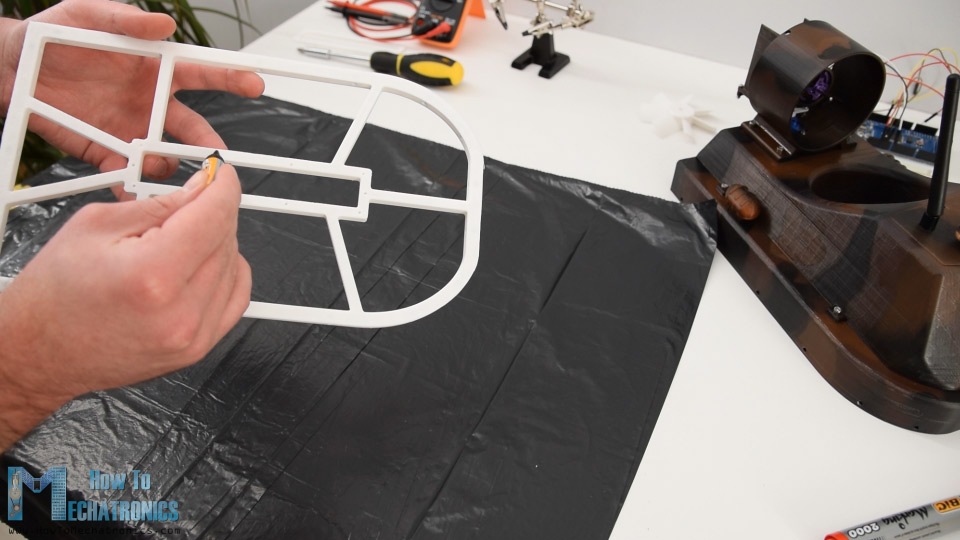
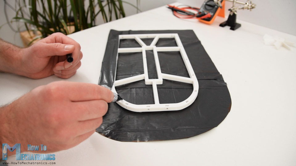
So first I applied an AC glue to the middle area of the holder, and glued it to the plastic bag. Then I offset the perimeter of the holder at around 6cm. I marked it at several points and then connected them together.
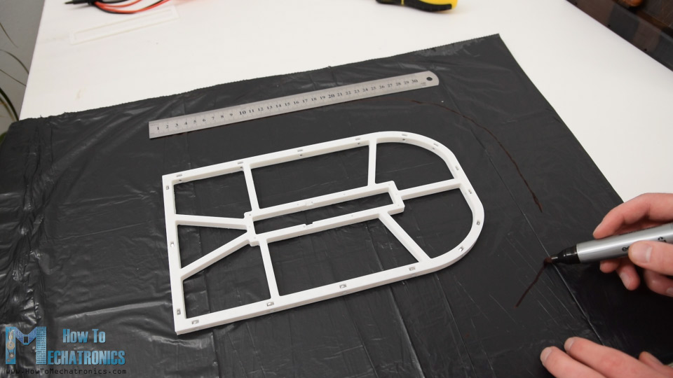
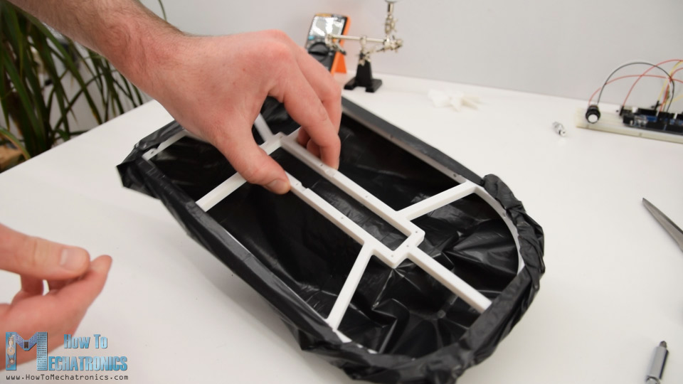
Using a utility knife, I cut the plastic bag to the proper size. Then I flipped the skirt, and added some additional holder to the bag where we previously glued it using the AC glue.
Next the outer of the bag needs to be glued to the top of the holder. Again, I used AC glue for that purpose and carefully secured the plastic bag to it.
Once done with that, here’s how the skirt should look like.
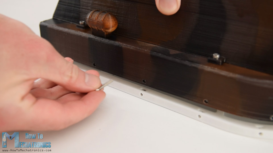
Next, I made holes through the plastic bag where the bolts should pass through. The skirt holder is just 1mm smaller then the hull of the hovercraft, so in combination with the plastic bag it fits into the hull perfectly. For securing the skirt to the hull, I simply fastened the M3 bolts around the whole perimeter.
There is one more thing to be done to the skirt and that’s cutting out central area of the plastic bag.
So, with this half of the air will directly inflate the skirt and then it will bleed out through this opening, creating an additional air bubble in the middle.
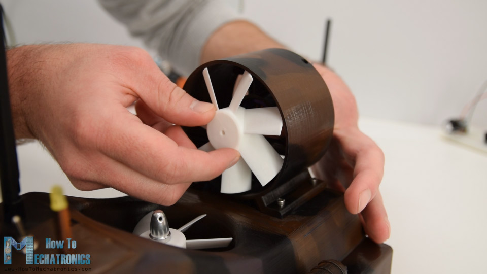
Finally, what’s left to be done is to attach the propellers to the brushless motors. For that purpose, I’m using the collet that comes with the brushless motor. It’s really simple and effective way of fastening the propeller to the motors shaft.
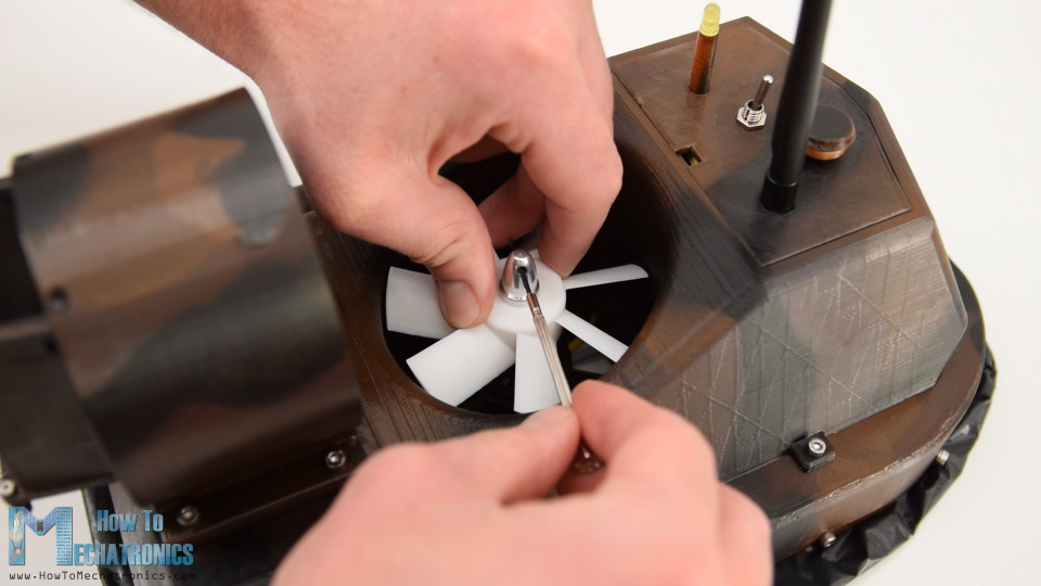
However, I lost the collet for my other motor, so I had to print a different version of the propeller to directly fit onto the motors shaft, which is 3.15mm. The print actually came out pretty good, it fitted and secured perfectly to the motor without even using a glue.
And that’s it, our radio-controlled hovercraft is finally done.
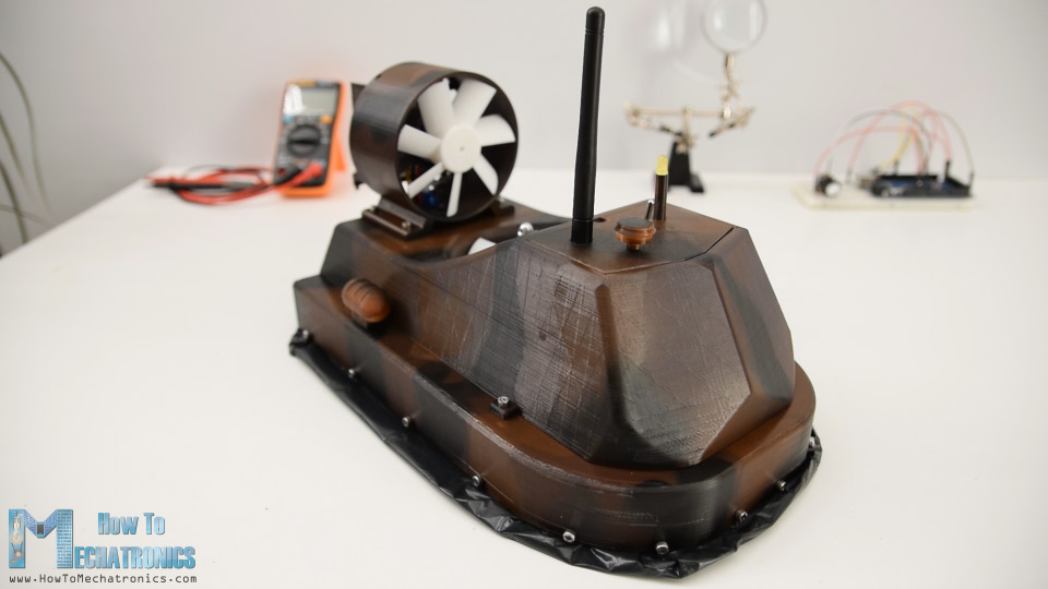
However, what’s left in this video is to take a look at the Arduino code and how the program works.
Arduino RC Hovercraft Code
Here’s the code for this DIY Arduino based RC Hovercraft project:
/*
         Arduino based RC Hovercraft
   == Receiver Code - ESC and Servo Control =
  by Dejan, www.HowToMechatronics.com
  Library: TMRh20/RF24, https://github.com/tmrh20/RF24/
*/
#include <SPI.h>
#include <nRF24L01.h>
#include <RF24.h>
#include <Servo.h>

#define led 10

RF24 radio(8, 9);   // nRF24L01 (CE, CSN)
const byte address[6] = "00001";
unsigned long lastReceiveTime = 0;
unsigned long currentTime = 0;

Servo esc1;  // create servo object to control the ESC
Servo esc2;
Servo servo1;

int esc1Value, esc2Value, servo1Value;
// Max size of this struct is 32 bytes - NRF24L01 buffer limit
struct Data_Package {
  byte j1PotX;
  byte j1PotY;
  byte j1Button;
  byte j2PotX;
  byte j2PotY;
  byte j2Button;
  byte pot1;
  byte pot2;
  byte tSwitch1;
  byte tSwitch2;
  byte button1;
  byte button2;
  byte button3;
  byte button4;
};
Data_Package data; //Create a variable with the above structure
void setup() {
  Serial.begin(9600);
  radio.begin();
  radio.openReadingPipe(0, address);
  radio.setAutoAck(false);
  radio.setDataRate(RF24_250KBPS);
  radio.setPALevel(RF24_PA_LOW);
  radio.startListening(); //  Set the module as receiver
  resetData();
  esc1.attach(7);
  esc2.attach(6);
  servo1.attach(5);
  pinMode(led, OUTPUT);
}
void loop() {
  // Check whether we keep receving data, or we have a connection between the two modules
  currentTime = millis();
  if ( currentTime - lastReceiveTime > 1000 ) { // If current time is more then 1 second since we have recived the last data, that means we have lost connection
    resetData(); // If connection is lost, reset the data. It prevents unwanted behavior, for example if a drone jas a throttle up, if we lose connection it can keep flying away if we dont reset the function
  }
  // Check whether there is data to be received
  if (radio.available()) {
    radio.read(&data, sizeof(Data_Package)); // Read the whole data and store it into the 'data' structure
    lastReceiveTime = millis(); // At this moment we have received the data
  }
  // Controlling servos
  servo1Value = map(data.j2PotX, 0, 255, 0, 50);
  servo1.write(servo1Value);

  // Controlling brushless motor with ESC
  // Lift propeller
  esc1Value = map(data.pot1, 0, 255, 1000, 2000); // Map the receiving value form 0 to 255 to 0 1000 to 2000, values used for controlling ESCs
  esc1.writeMicroseconds(esc1Value); // Send the PWM control singal to the ESC

  // Thrust propeller
  esc2Value = constrain(data.j1PotY, 130, 255); // Joysticks stays in middle. So we only need values the upper values from 130 to 255
  esc2Value = map(esc2Value, 130, 255, 1000, 2000);
  esc2.writeMicroseconds(esc2Value);

  // Monitor the battery voltage
  int sensorValue = analogRead(A0);
  float voltage = sensorValue * (5.00 / 1023.00) * 3; // Convert the reading values from 5v to suitable 12V i
  Serial.println(voltage);
  // If voltage is below 11V turn on the LED
  if (voltage < 11) {
    digitalWrite(led, HIGH);
  }
  else {
    digitalWrite(led, LOW);
  }
}
void resetData() {
  // Reset the values when there is no radio connection - Set initial default values
  data.j1PotX = 127;
  data.j1PotY = 127;
  data.j2PotX = 127;
  data.j2PotY = 127;
  data.j1Button = 1;
  data.j2Button = 1;
  data.pot1 = 1;
  data.pot2 = 1;
  data.tSwitch1 = 1;
  data.tSwitch2 = 1;
  data.button1 = 1;
  data.button2 = 1;
  data.button3 = 1;
  data.button4 = 1;
}Code language: PHP (php)
Description: So first we need to include the RF24 library for the radio communication as well as the servo library for controlling both the servo and the brushless motors. Then we need to define the radio and the servo objects, some variables need for the program below as well as the structure of variables which are used for storing the incoming data from my DIY RC Transmitter. For more details how this communication works I would suggest to check my particular tutorial for it.
In the setup section we need to initialize the radio communication as well as define the pins to which the servo and ESCs are connected.
In the loop section we read the incoming data from the transmitter and use that values for controlling the servo and the brushless motors. So, joystick incoming data which varies from 0 to 255 is converted into a values from 0 to 50 and we use these values to control the position of the servo.
With the same method we control the brushless motors using the ESCs. The incoming data which is from 0 to 255 is converted into a values from 1000 to 2000 and using the wirteMicroseconds() function we send this data to the ESC as a control signal.
For monitoring the battery voltage, we read the analog input coming from the voltage divider and with some simple math we convert the input values into real value of the battery voltage. If the battery voltage drops below 11V we simply light up the indicator LED.
And that’s it. In case you need some more details, you can check out the other suggested tutorials and so you will be able to fully understand how everything works.
I hope you enjoyed this tutorial and learned something new. Feel free to ask any question in the comments section below and check my Arduino Projects Collection.
Hello Dejan
Thank You for Your impressive work. I have built a Hovercraft and is very satisfied with it but I have a problem.
When I use the transmitter the response from the transmitter is delayed with about 3-4 seconds. I have tried to change the ´´serial.begin´ with no effect. I can´t find any problem with the code and the radio voltage is stable.
Have You experinced this and have You any tips how to solve the problem.
Sincerely
Bengt-Åke
Hey,
Thanks, I’m glad you found the project interesting.
That’s strange behavior, I haven’t experienced such a problem with the radio communication. I can’t think of anything that could cause such a delay problem at this time.
Try the radio communication with a simpler example code to see whether your system is working properly. If it does, try getting rid of some code lines from the Hovercraft code, to try to find the issue. Try removing the Serial.print() lines as they can slow the program significantly.
Hey Dejan,
When putting the files into the 3D print software the components are to large. What scale do you have the STL files as???
cheers
Well it depends on the bed size of your 3D printer. I used the CR-10 which has a print bed 30x30cm. If you are using smaller printer they parts will be out its bed.
Hey Dejan,
Firstly fantastic site, but i am slightly confused, i’d like to build the controller and the hover receiver as i want to adapt it for a boat project but when i look at the project parts lists there seem to be a number of items not listed, is there a complete list somewhere please for each project?
as much info as possible on the parts as it appears to be quite hard to get parts in the UK 🙁
Hey, thanks! Well I don’t have a specific full part list, but you can see all the required components from the circuit diagrams.
Hi Dejan,
I have made this cool project, but I have a problem with the ESC’s they make this beep sound and get really hot. When I adjust the potentiometers on the radio controller nothing happens. I have tried to reconnect the wires going from the ESC’s to the engine, but this doesn’t change anything. Hope you can give a hint on how to troubleshoot this issue.
Thanks
Hey, do you have enough battery power and what kind of controller are you using? Make sure you give a proper 50Hz PWM signal to for controlling the ESC. Check my other detailed tutorial about controlling BLDC motors using Arduino for more details.
Hi Dejan, I want to start with the printing of the hovercraft. Before I start, are the demensions correct?
For the file “boddy6”: 278.0×147.0x70.0
Thanks for the answer.
Yes, those are correct dimensions.
I want to try the project but the links to download 3D vision are dead, can you corect this ?
Hey, try to use different web browser in case you have problem downloading the files.
Nice and educational project. I made both. Now for the code. This is a bit too difficult for me.
Is there a full Arduino code for the Ardino RC transmitter to control the Hovercraft?
Thank you very much.
Hey, thanks! The full Arduino code for the RC Transmitter can be found on the particular RC Transmitter project.
Still having fun with this great project…
If you have an old, half-broken umbrella then these provide some great parts. We’re using the umbrella lining as an upgraded skirt material (versus plastic bag). And the umbrella structure provides some good sized stiff wires for the rudders.
ps. your Fusion project doesn’t include the smaller, bottom-most retention bracket body that you made to securely sandwich the skirt. (perhaps its in stl files, but I just made one from the larger, upper bracket.
Making this project with my sons, it’s a great project. Thank you for the great work that you are publishing. I appreciate it so much.
We might well upgrade later to using an arduino, but for now we’re using some off-the shelf control parts. A Flysky i6x transmitter connects easily to a FS-X6B receiver (PWM output) which is so tiny and can directly signal the motors/servos … the voltage monitoring is displayed on the i6x. You might consider an addendum for something like this, as it makes it easier for newbies to get a working one going, if they’re not as arduino/programmer savvy. (Or provide an alternative to making one of your custom transmitters.)
Please warn everyone to wear safety glasses at a minimum when playing with these homemade EDFs. We printed initially in PLA, and i’m a bit scared of it shattering … so we’re switching to PETG or ABS. Maybe not as much of an issue when operating remotely, but any close up testing could be dangerous to your face.
Thanks for the STEP files. I managed to modify them with some added joints, so that they could print on a smaller 25cm Prusa print bed.
I haven’t yet, but consider configuring the ESC from “smooth” to “accelerated” for the thrust, as it might make the thrust acceleration a bit more snapper and less lag.
Doesn’t the voltage dividing resistors, for the voltage detection, end up being a constant drain on the battery? (Meaning, when the system is otherwise “off”, the battery will drain down due to the voltage detection … right?) how to fix that?
Well yeah, that’s a good point. But if you connect the voltage divider after the power switch there won’t be any current flow through it.
Where did you ground the voltage divider? Btw awesome project
Thanks! Well you can ground it at any ground point.
I have an Arduino Nano. How do I step the voltage down to 3.3V for the NRF24L01.
This is a great project and very well explained.
However since I already have a standard R/C transmitter and receiver with 9 channels, do I technically still need an Arduino to control the motors and servo or can this all be done from the receiver module directly by connecting the receiver to the ESCs and servo?
What actual value is the Arduino adding here (apart from monitoring the battery voltage)?
Thanks.
Thank you!
Yes, you can absolutely make the project with a standard RC transmitter and receiver. I just wanted to make a cool Arduino project which will include brushless motors control, so that’s why I used an Arduino.