In this tutorial I will show you how I build an Arduino based RC Airplane, and also, I will show you how to control it using the custom build Arduino transmitter that I built in one of my previous videos.
You can watch the following video or read the written tutorial below.
Overview
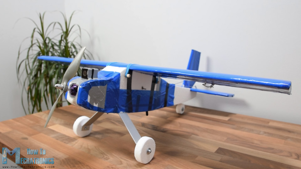
So, the airplane is entirely made out of Styrofoam. For making the shapes I used my Arduino CNC Foam Cutting Machine which I already showed you how I built it in a previous video. Although I’m using a CNC machine for building this Arduino RC airplane, I can still say it’s 100% DIY because the CNC machine is also a DIY build.
Moreover, the control of the airplane is also 100% DIY, based on Arduino and the NRF24L01 module for the radio communication.
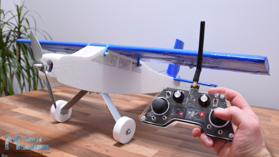
Using the right joystick of the transmitter, we can control the ailerons and the elevator of the airplane, and using the left joystick we can control the rudder and the throttle.
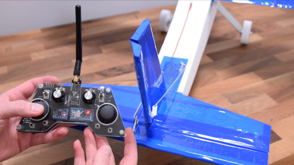
In addition to that, using the right potentiometer we can adjust the controls responsiveness, or reduce the amount of servo travel, and using the left joystick we can sub-trim the rudder or adjust the neutral position of the servo arm.
Oh, and I almost forgot the mention, the main feature of this Arduino RC airplane is flying, so yeah, it can fly.
Designing the RC Airplane – 3D Model
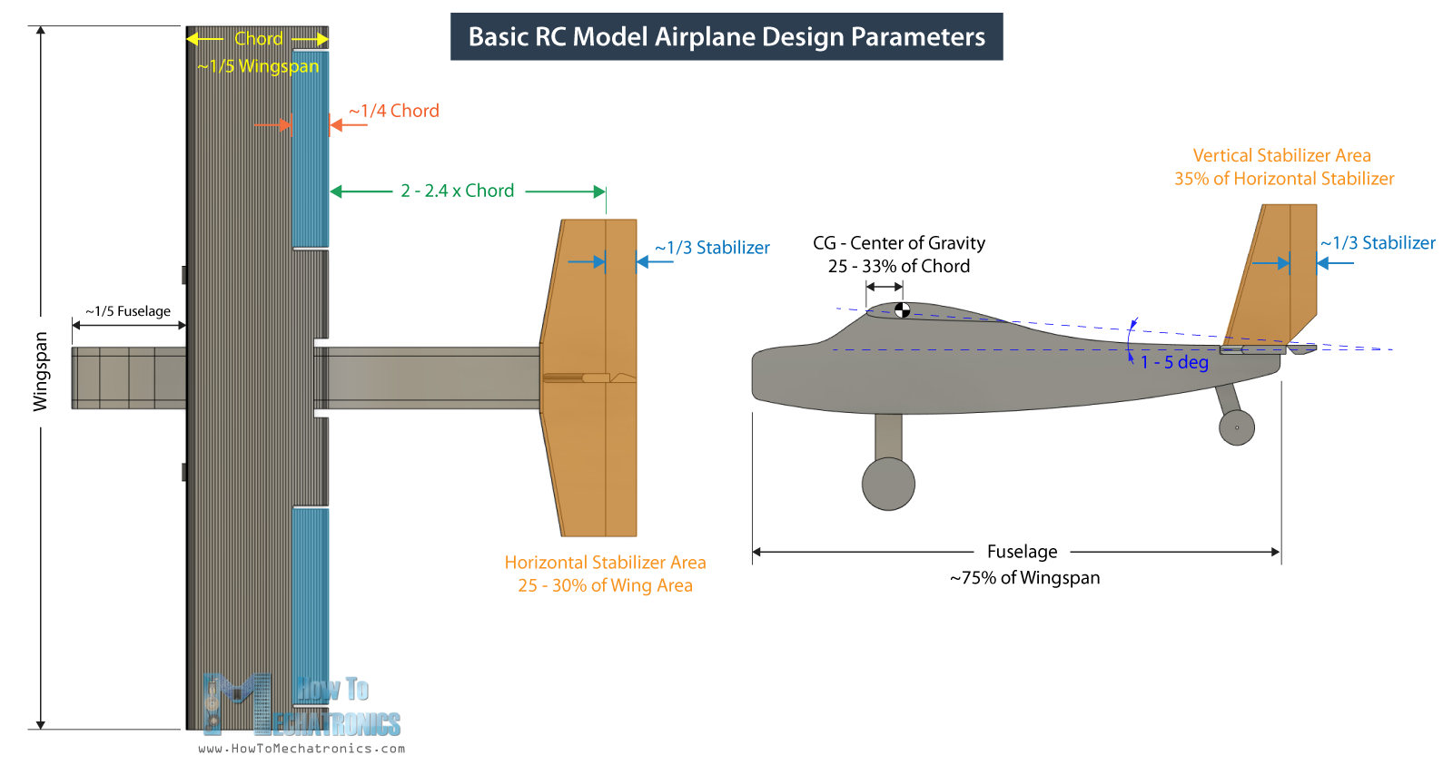
I started by designing the airplane using a 3D modeling software, Fusion 360 in this case. I made the design by looking at some commercial RC airplanes and following some basic guidelines or rule of thumbs for model airplane parameters.
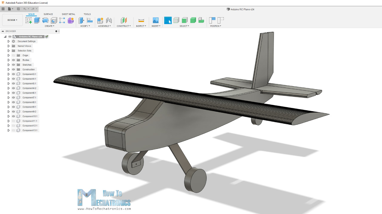
The starting point is the wingspan, and I chose to be 80cm. From there we get the fuselage length, which is generally 75% of the wingspan. As for the airfoil, or the wing cross section I chose the CLARK Y Airfoil, which a popular choice for RC airplanes.
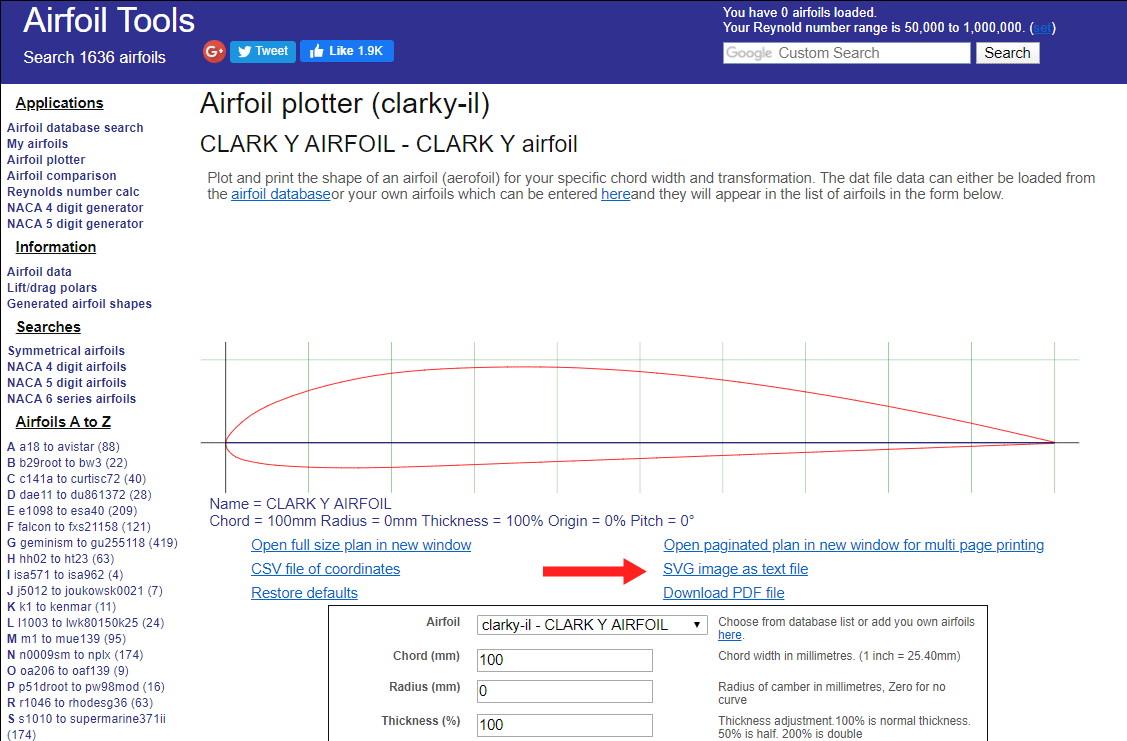
I downloaded the airfoil shape from airfoiltools.com as .SVG file and then I imported it into Fusion 360. I adjusted the size appropriately, so that the wing chord, or the length of the wing in stream-wise direction is around 1/5th of the wingspan.
The horizontal and the vertical stabilizer are also sized according to those basic guidelines. Here are some those basic RC model airplane design parameters:
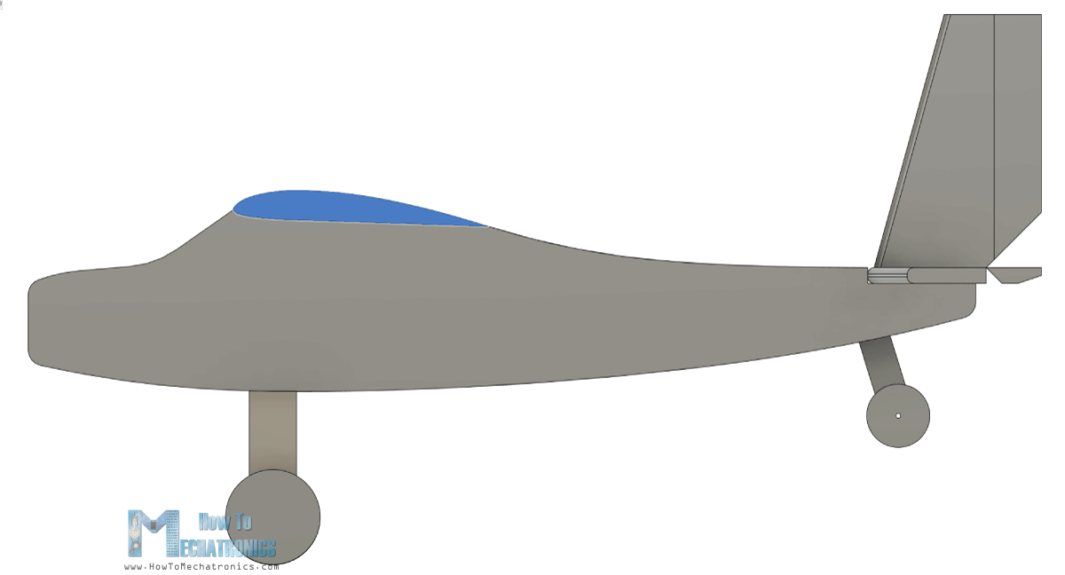
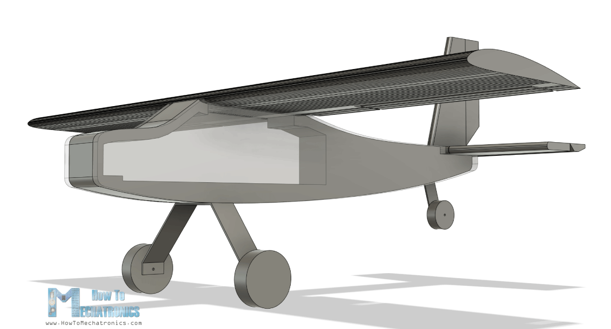
The fuselage of the airplane will be made out of two 10mm sides and a 50mm core which will be hollow to accommodate the electronics.
You can download the 3D model from the links above. There are two version of the Airplane. The version 1 is the one shown here in the images, and version two has a bit smaller nose and the motor can be placed more to the front in order to improve airflow.
Generating G-codes for my DIY CNC Foam Cutter
Now, as my Arduino CNC Foam Cutting Machine work area is limited to 45cm, and the fuselage is 60cm in length, I had to make the fuselage out two parts.
So, I cut the fuselage at 34cm from the front point, and made a new sketch in which I projected the shape and added a point near it. Next, in the manufacturing tab of Fusion 360, I can generate the G-code for cutting the shapes.
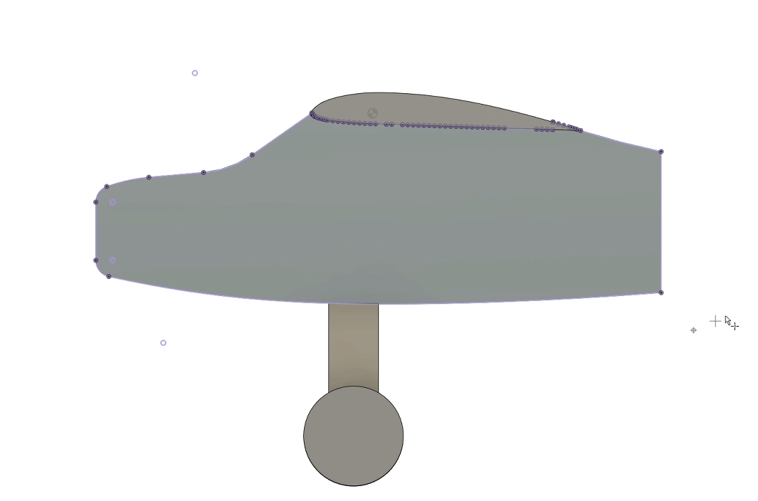
Here, first I made a new setup where I selected the sketch as a model, selected the point I added earlier as origin for the setup, and adjusted the X and Y axis appropriately.
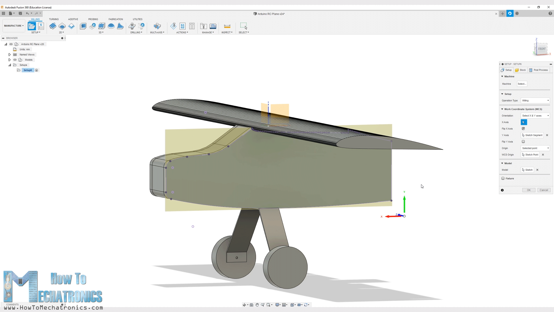
Then I chose the 2D contour operation and selected or generated a new tool, with diameter of 3mm, because that’s the approximate size of the cuts that the hot wire makes when passing through the Styrofoam. Here we can also set the cutting feedrate which depends on the hot wire itself and the hardness of the Styrofoam. I set it to 150 mm/m.
Then in the geometry tap we can select the contour or the shape that needs to be cut. As for the heights I set them all to 1mm as there isn’t any Z axis movement on my foam cutter machine. Lastly in the Linking tap I selected the entry position to be the edge located near the origin point.
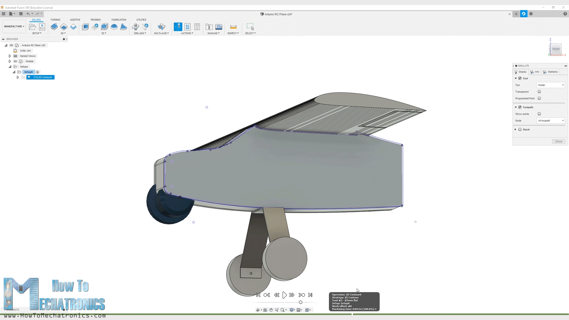
With this the toolpath is generated and we can take a look at it by clicking the Simulation button. The toolpath should be a closed loop single pass, and if that’s the case, we can finally generate the G-code. For that we can go to Post Processes, select the GRBL firmware, select the output folder, name the file and click the post button.
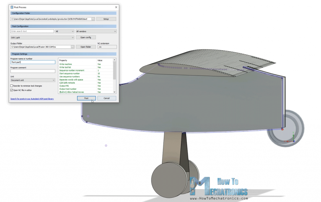
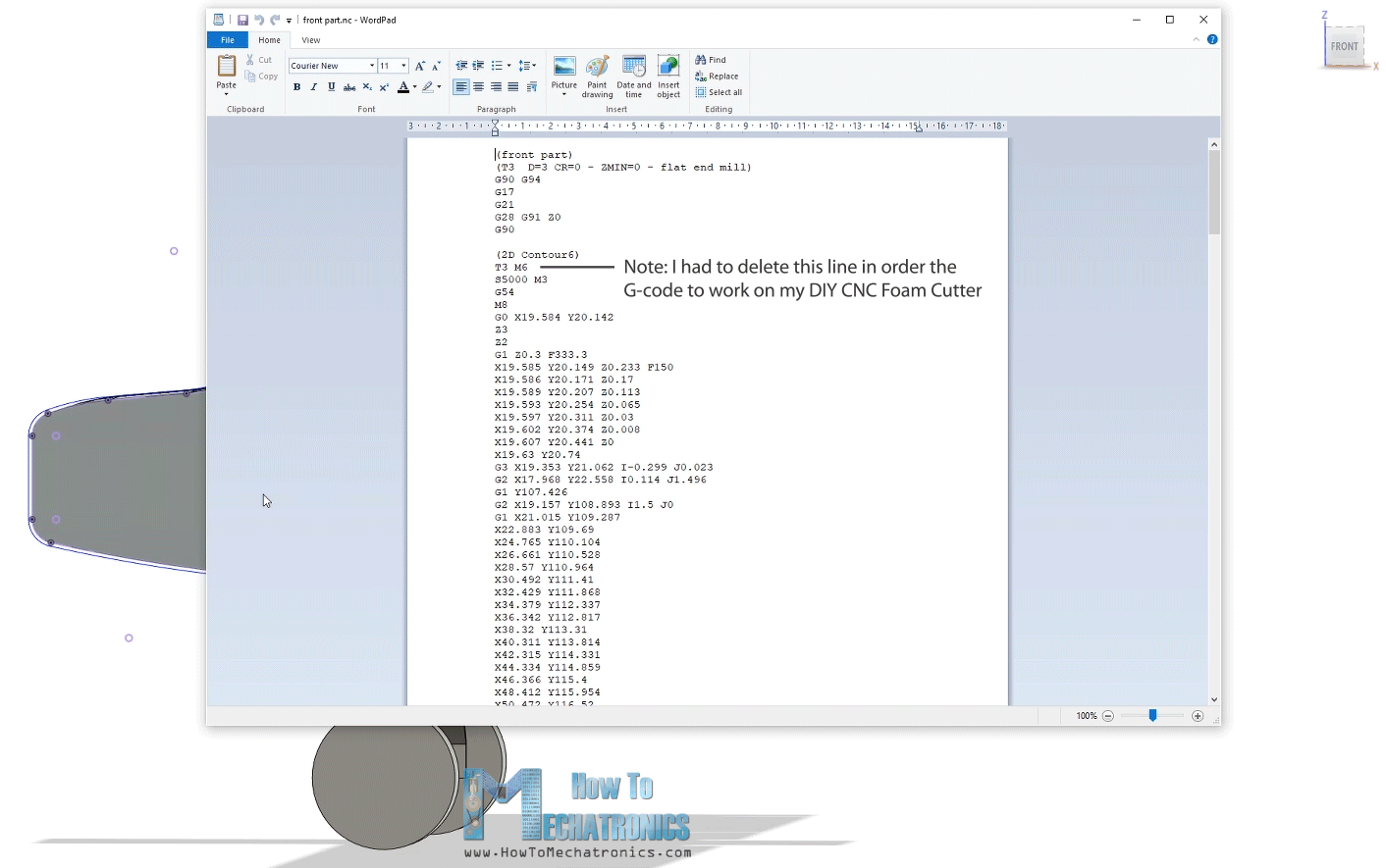
Then we can save the file, and we can see the G-code in the WordPad editor or something similar.
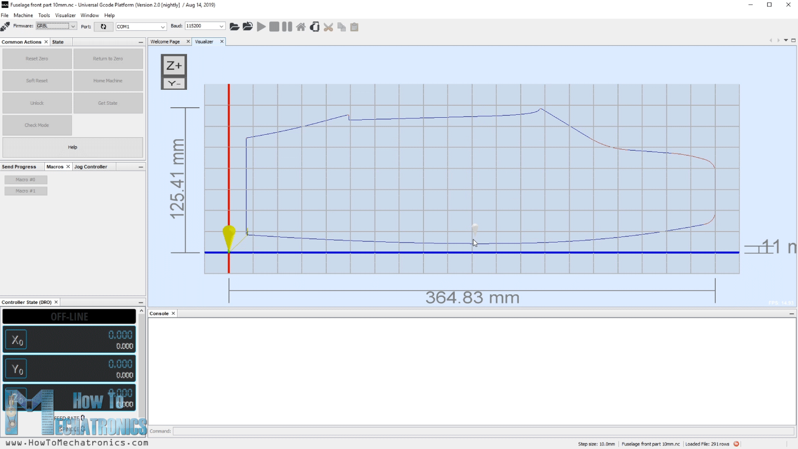
So now once we have the G-code file, we can load it into the Universal G-code sender and send the G-code to the CNC machine to make the shape.
We can note that the process that I’ve just showed you is probably not the best one or not professional at all, but still it does the job for getting the G-codes to work with my DIY CNC Foam Cutting Machine. Of course, for more details about this DIY CNC machine you can check my particular tutorial for it, the link is in the description of the video.
You can download the G-code files here:
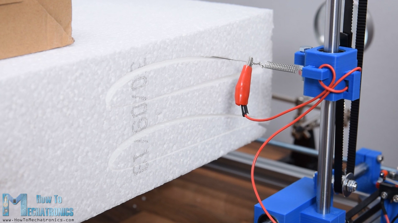
As I said, for the sides I used 1cm tick Styrofoam and for the middle I used 5cm tick Styrofoam.
As for the wing, I used 10cm tick Styrofoam which I cut it around 30cm wide because that’s the maximum span my hot wire machine can cut. I placed two wing profiles in single G-code file and I cut couple of them.
In order to get the 80cm wingspan I will glue 3 pieces of 27cm, and in order to get them straight, I manually cut off the ends of the pieces so that they are perpendicular.
Assembling the RC Airplane
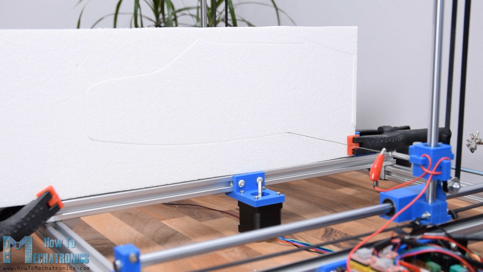
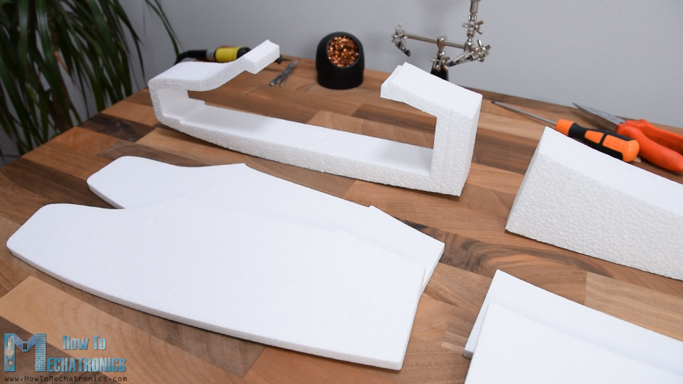
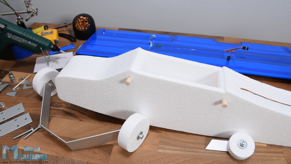
So here are all the Styrofoam pieces I cut with CNC machine. Three pieces for the front, three pieces for the back and three pieces for the wing. Now I can start assembling them.
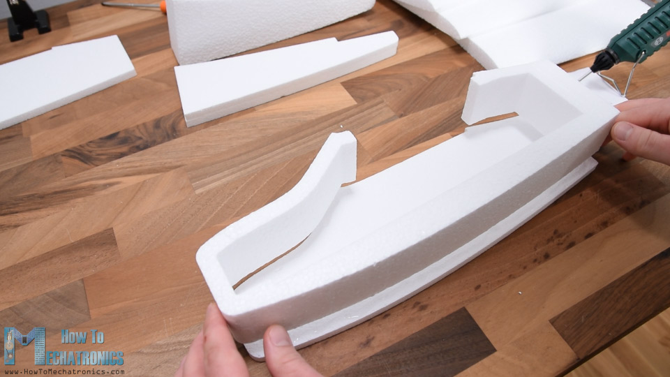
I will start with the front part. I’m using a glue gun for gluing the pieces together. The hot glue was melting a little bit the Styrofoam but still I was able to glue them using this method.
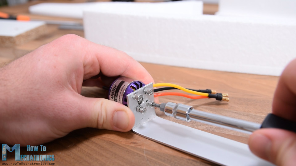
Another good way to glue Styrofoam is with 5-minutes epoxy. Before gluing the other side, I will make the holder for the motor. For that purpose, I’m using 30mm wide aluminum profile which is pretty light weight. I cut the profile at around 18cm, marked the holes for mounting the motor, and drilled them using 3mm drill bit. Then I bent the profile at 90 degrees. I secured the motor to the holder using some M3 bolts.
Using this assembly, I made a hole through the front part of the Styrofoam. Then, using a utility knife, I enlarged to hole to 30mm in diameter, same as the motor diameter.
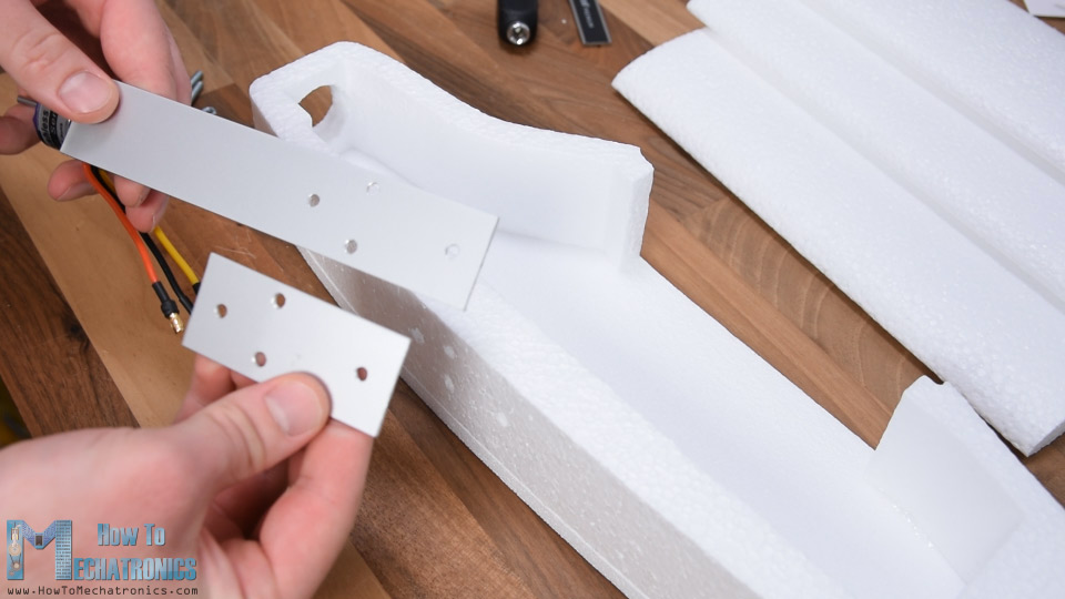
Next, on the other side of the motor holder I made 4 holes which will serve for securing the holder in place and also for attaching the landing gear. I marked the location of these holes on the fuselage and using a 4mm drill bit I made holes through the Styrofoam manually. I made another aluminum piece around 7cm long with the same holes, and now I can use it for securing the motor holder.
Using M4 bolts we can easily secure the motor holder in place without damaging the Styrofoam. However, I will do that later, so I removed them and I continued with gluing the other side. Using the same method, I glued the back pieces as well.
The next step is the marriage, or connecting the front and the back part of the fuselage. In order to make the connection stronger, I will add simple barbecue sticks in between them.
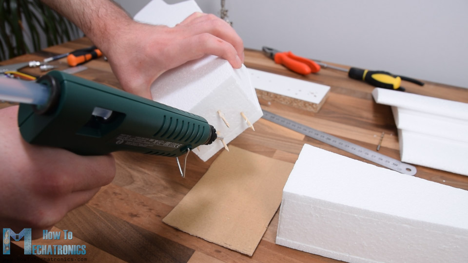
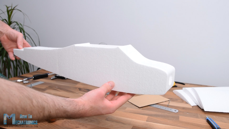
I would suggest even using some bigger sticks because when the airplane will crash it might easily break here. I added some decent amount of hot glue to the connecting site and squeezed them together. So here it is, the fuselage is ready and I think it looks pretty cool.
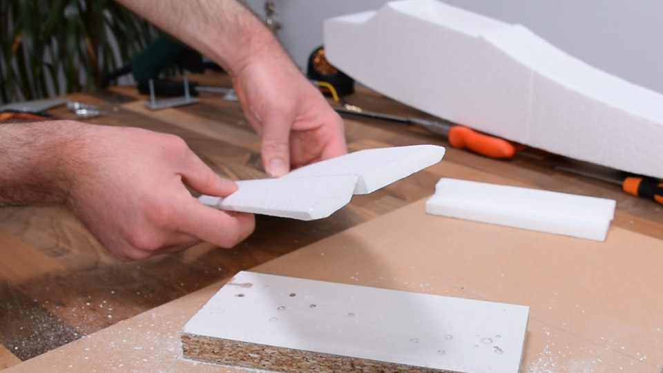
Next, using a utility knife I’m cutting two pieces of 10 mm stick Styrofoam which will be the horizontal and the vertical stabilizers. I beveled the edges so they look better and also be a little more aerodynamic. The stabilizers will be directly glued to the back side of the fuselage but before I do that, I will first make their controller surfaces.

For that purpose, I cut around 1/3rd of their length, and that will be their control surface or the elevator for the horizontal stabilizer and the rudder for the vertical stabilizer. In order to be able to hinge the control surfaces on the stabilizers I needed to bevel their contact surface. Again, I did that using a utility knife, and we actually need quite sharp one for getting these cuts clean.
I continued with making the stabilizers a bit more aerodynamic. For that purpose, I used a sandpaper and made their leading edges rounded. I also sanded the trailing edges a little bit.
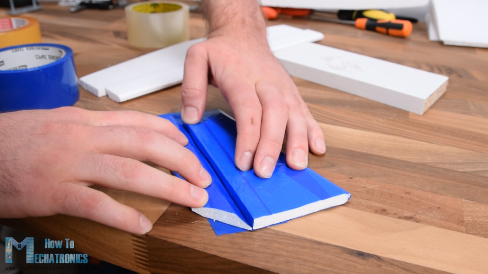
Now, as the Styrofoam is quite fragile, I’m going to wrap the whole area of the stabilizers and their control surfaces with a simple packing tape. This will not only make the parts stronger but also increase the aerodynamic, as the tape is much smoother than the Styrofoam itself.

After wrapping it, I cut the rudder bottom part at 45 degrees, in order to make space for the elevator to be able to move freely.
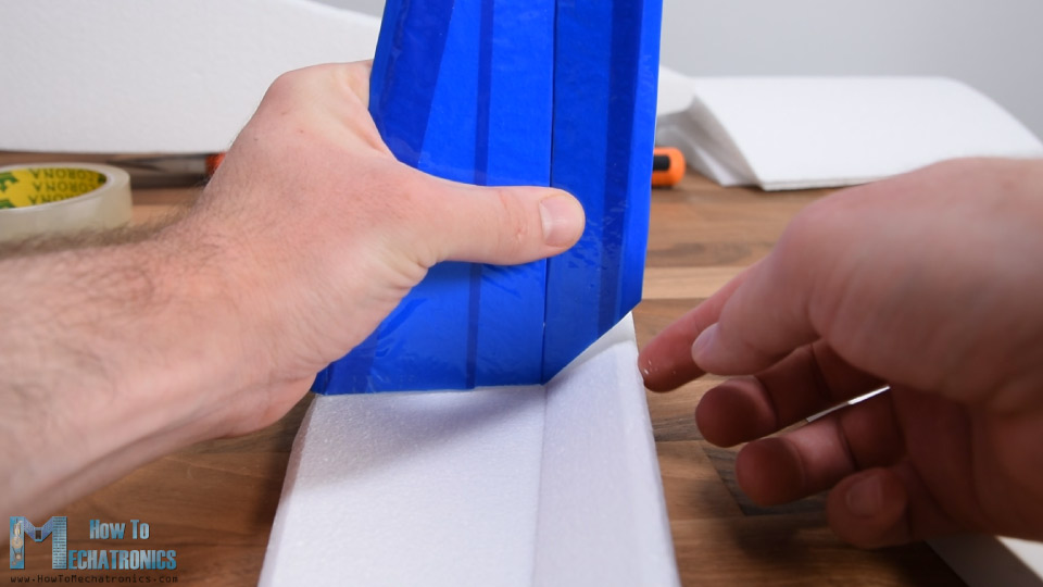
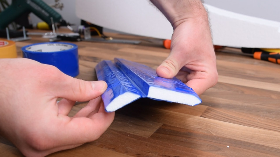
Now finally, I can make the hinge for it, and I’m doing that using the packing tape again. So, I just connected the two parts together with the tape, and that makes quite strong hinge.
I repeated this process for the horizontal stabilizer as well. For making the hinge even stronger we can also add tape on the other side. Using the same tape, I wrapped the sides and with that the two stabilizers are done.
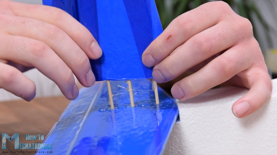
I moved on with gluing the horizontal stabilizer to the fuselage using a hot glue. For securing the vertical stabilizer, first I inserted and glued 3 barbecue sticks through the horizontal stabilizer and the fuselage. Then I put some hot glue on them and the contact surface and pushed the stabilizer down firmly.
With this we are done with the stabilizers and we can move on with making the wing.
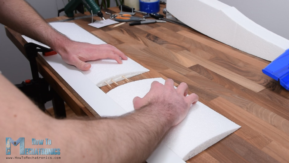
So, as I already said, the wing will be made out of 3 pieces because of the limited work area of my DIY CNC foam cutting machine. Again, I’m using barbecue sticks for providing additional strengths when gluing the pieces. For attaching them precisely in line, I’m using a straight wooden strip on which I can slide the pieces.
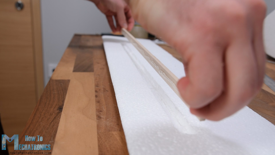
Once done with that, the wing is actually quite fragile as it’s long and tin. Therefore, I will reinforce it by adding a wooden stick to it. I cut the stick to size and marked the wing where I need to make a pocket so I can fit the stick in it. Using the utility knife, I slowly and carefully made the pocket. I added some hot glue to it and secured it in place without disturbing the airfoil shape too much.
Now the wing is much stronger with the wooden stick in place. Although stronger it would still easily break apart if it hits the ground, so therefore I will wrap it all with the packing tape as same as I did with the stabilizers. I started adding the tape from the back side or the trailing edge of the wing, to the front side or the leading edge.
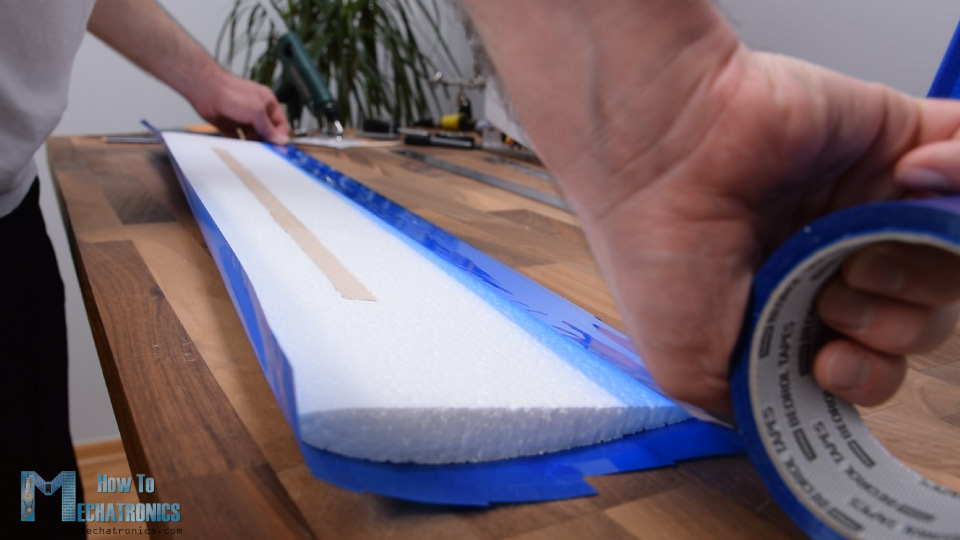
In this way the incoming air from the front won’t tend to detach the tape. Although this process looks pretty easy, it can be a bit annoying if you don’t have steady hands and enough patient. I think the wing came out just perfect. Now it is much stronger, more aerodynamic and it looks quite good.
All right, the next step is making the control surfaces of the wings or the ailerons. I’m going to make them 22cm wide and about 1/4th of the wing chord in length. In order to be able to move freely I cut off like half centimeter of it.
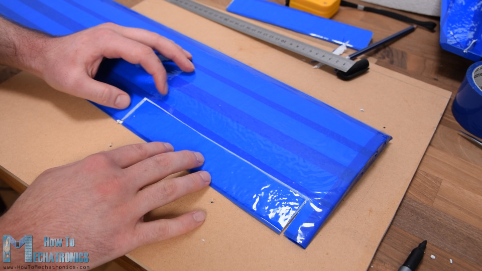
And of course, I wrapped all edges exposed with the cutting. Next, I beveled the bottom part of the aileron at 45 degrees, and in the same way as show earlier, now I can hinge it to the wing. In order to fit on the fuselage and be able to easily attach the wing to the fuselage I had to make one more recess in the middle the wing.
Next, it is time to install the servo motors for controlling the ailerons. I’m using the 9g micro servos. I marked the location where they will be placed and using the utility knife, I carefully made an opening in the wing so that the servo can fit it. Meanwhile, I removed the servos mounting brackets so that thier shape is simpler. I put some glue on the servo and inserted in the opening.
Using the utility knife, I made a small groove from the servo to the center of the wing so that I can fit the servos wiring in it. Finally, I covered everything with a piece of tape. I repeated the same process for the other side as well.
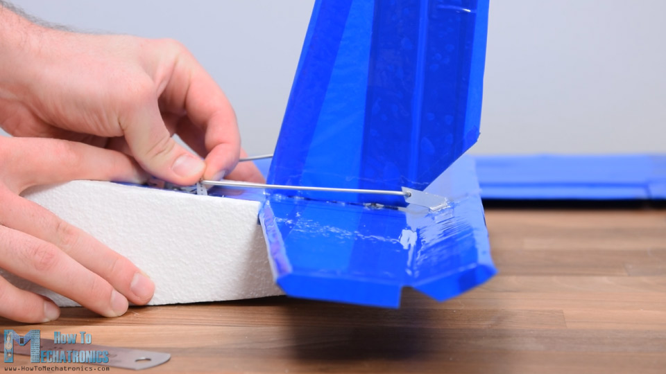
I continued with making the control horns. I’m going to make them out of the aluminum profile that I used before for making the motor holder. I draw the shape by hand to approximately match the servo motor horn height and to hang over the hinge point. I cut the shape using a hacksaw.
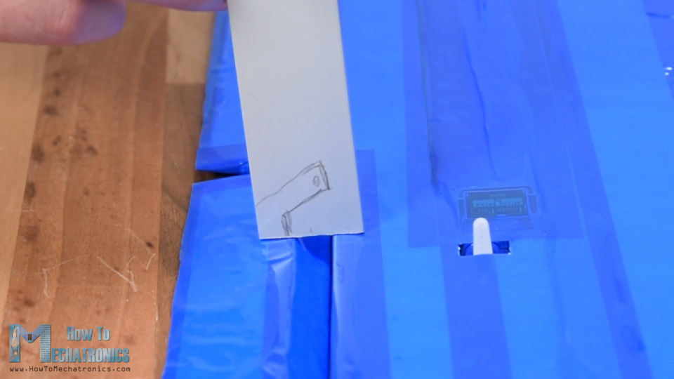
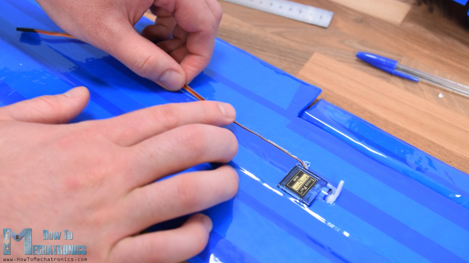
I will use 2mm steel wire as control rod so I made an opening in the horn using a 2.5mm drill. I made a small groove in the aileron and glued the horn in place. Then I measured how long the control rod should be and made it out of 2mm steel wire with the help of some pliers. We need to note that when measuring and inserting the control rods, the servo motors need to be in neutral position.
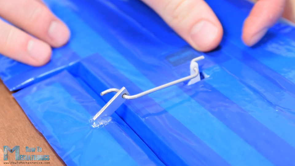
We can do that by manually placing it in the middle of its motion range, or by connecting it to a servo tester or do that with an Arduino. I repeated the process for the other side, and with that the wing is now completely done.
Next, I need to install the servos for controlling the rudder and the elevator. I’m using the same 9g micro servos here as well, and the process of installing them is actually pretty much the same as I’ve just explained. First, I marked the location, made the opening using a utility knife and glue the two motors in place. Here, they are next to each other but with their output shafts on the opposite side.
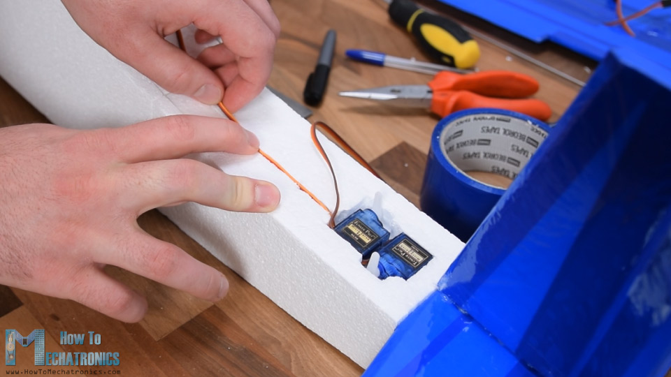
Again, I made a small groove in the fuselage in order to conduct the servos wiring to the electronics compartment. I covered the servos with a piece of tape and made openings for the servo horns. In the same way shown earlier I made the control horns and glued them in place using a glue gun. Lastly, I made the appropriate control rod and installed them accordingly.
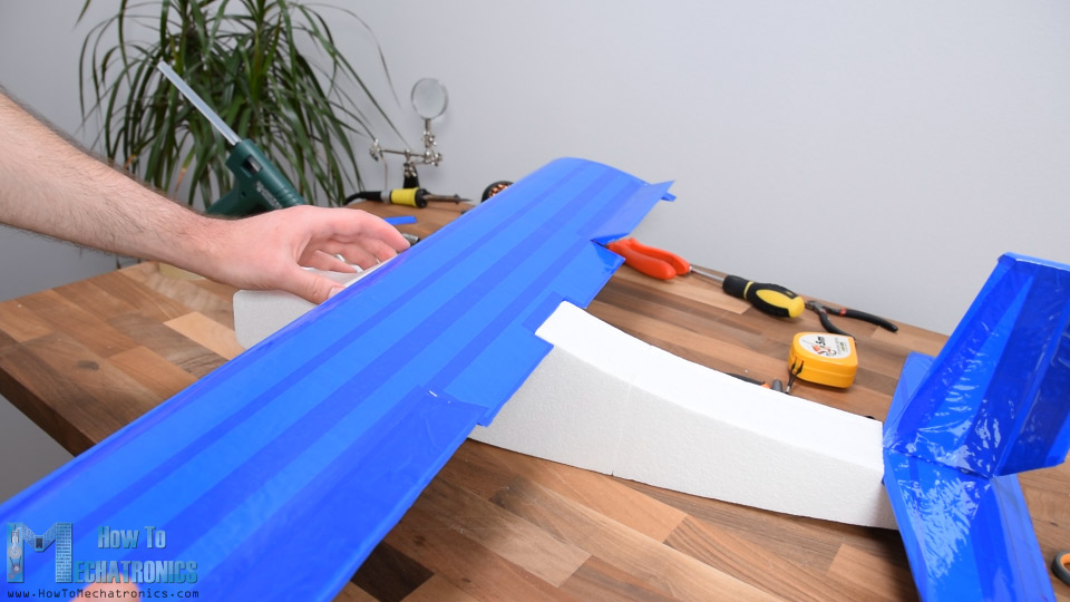
Ok, next I’m going to install two 8mm wooden rods which will serve for securing the wing to the fuselage. I made the holes manually using a 6mm drill bit. The rods should hang over around 1cm on both sides. I secured them to the fuselage with some hot glue as well and here’s how they actually work.
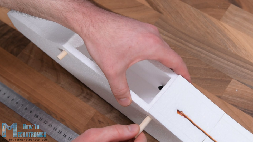
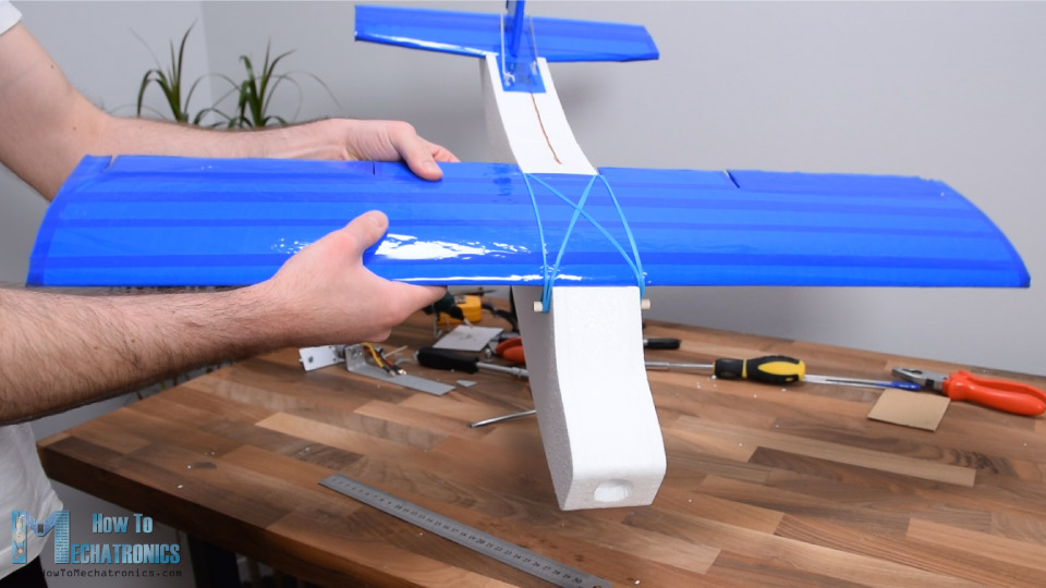
We use rubber bands for securing the wing to the fuselage. In that way the wing can be easily removed and in case of crushing the rubber bands will significantly reduce impact to the wing. At the same time the assembly is plenty strong.
Next, I’m going to make the landing gear. For that purpose, again, I’m will use the aluminum profile and wheels made out of Styrofoam. I made them using the CNC machine as shown earlier. I made little grooves on the aluminum profile so I can easily bend it. Here’s how the landing gear should actually look like.
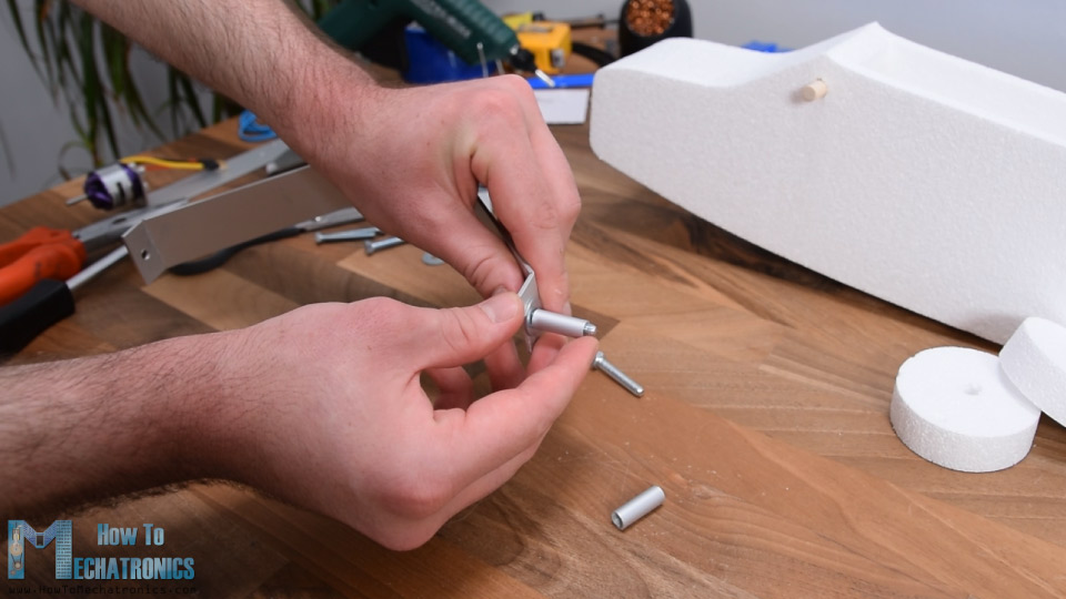
For attaching the wheels to the profile, I will use M5 bolts and an aluminum tube with 6mm inner diameter. The tube is secured to the bracket using the M5 bolt and nut, and on the sides, I added M5 washers so the wheel can rotate around the tube freely. With the same method I made the wheel for the back side of the airplane.
Ok, so now all the components are ready and before I assemble them let’s take a look at the electronics of this project.
Arduino RC Airplane Electronics – Circuit Diagram
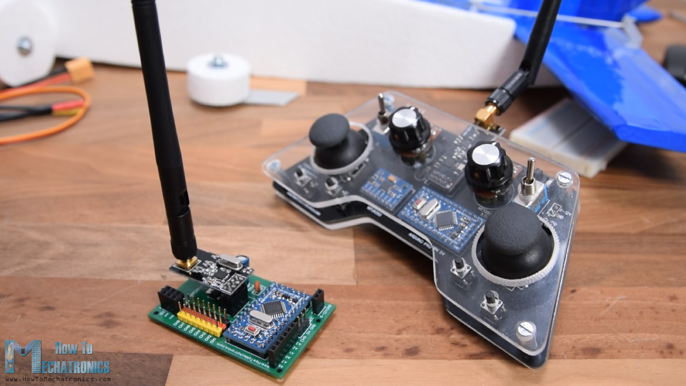
So, as I already said, this RC airplane is entirely based on the Arduino, both the Transmitter and the Receiver are custom builds based on the Arduino Pro Mini board.
I already have detailed tutorials how to build and how the transmitter and the receiver work, so you can check them out for more details. Here I will explain the circuit diagram and the working principle of this Arduino RC airplane and how everything needs to be connected.
You can get the components needed for this project from the links below:
- NRF24L01 + PA + LNA …………..…..……. Amazon / Banggood / AliExpress
- Arduino Pro Mini………………..……….….. Amazon / Banggood / AliExpress
- Servo Motor …………………………………… Amazon / Banggood / AliExpress
- Brushless Motor ………………………..…… Amazon / Banggood / AliExpress
- ESC 30A ……………………………….………… Amazon / Banggood / AliExpress
- Li-Po battery ……………………..…………… Amazon / Banggood / AliExpress
Disclosure: These are affiliate links. As an Amazon Associate I earn from qualifying purchases.
So, the radio communication is based on the NRF24L01 modules. Although it might look a bit complicated, this DIY Arduino transmitter is actually pretty simple. It has several controllers, the joysticks, the potentiometers and some buttons, and it constantly sends their data to the receiver. The receiver accepts this data wirelessly through the NRF24L01 module and it outputs appropriate commands to the servos and the brushless motor for controlling the airplane.
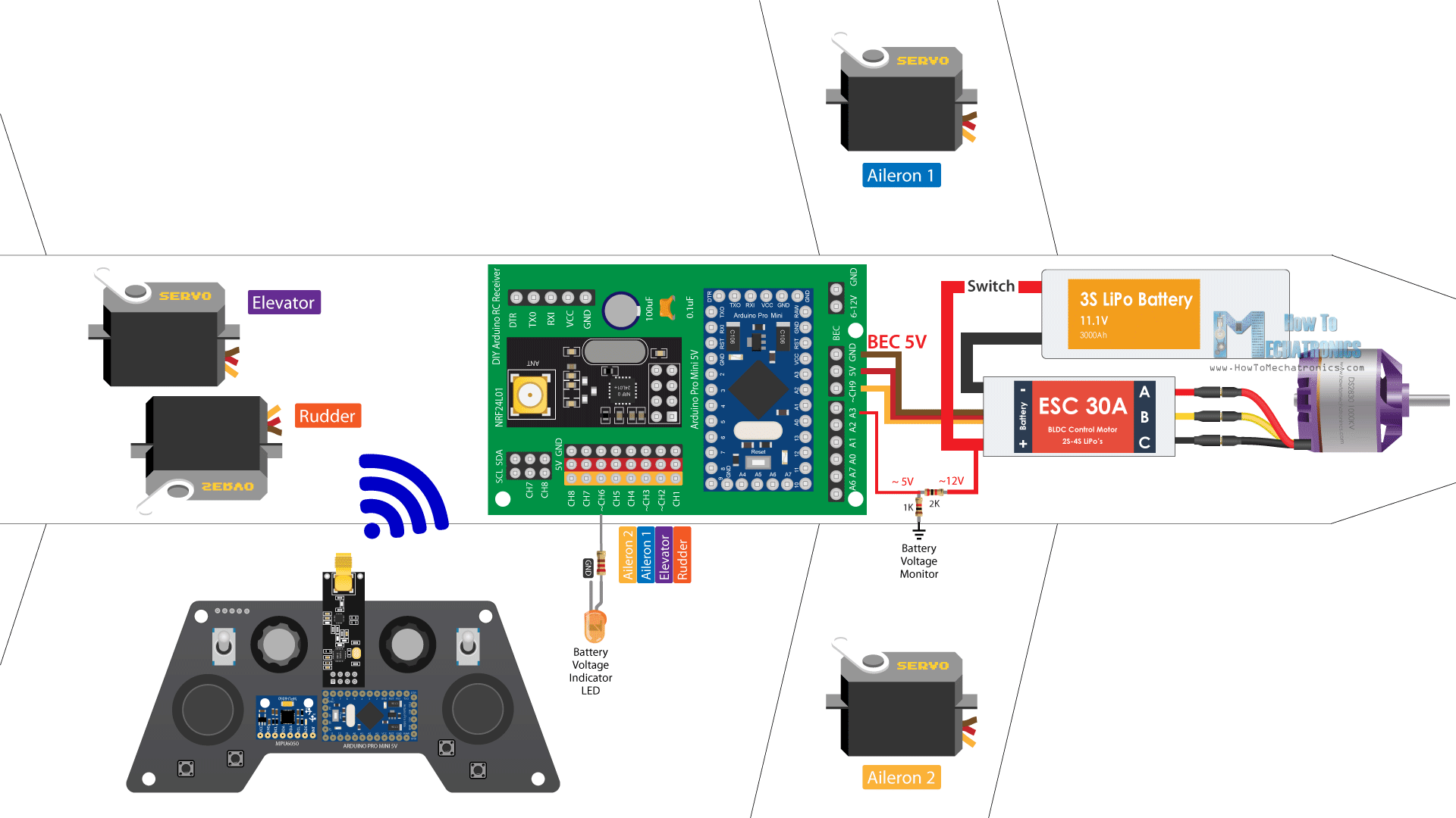
Controlling servos and brushless motors with Arduino is also quite simple, so therefore this entire Arduino RC airplane concept I think is not that hard to be understood. The brushless motor I’m using in this project has a rating of 1000KV and it requires 30A ESC. The ESC drives the motor and also provides power to the Arduino and the servos through its Battery Eliminator Circuit feature which outputs 5V. And the power to the ESC and the brushless motor comes from a 3S Li-Po battery.
I added one more feature to this airplane, and that’s a simple LED which will indicate if the battery is empty. Using a simple voltage divider, we drop the 12V coming from the Li-Po battery to around 5V so we can read them with the Arduino analog input and so know when the battery will drop below 11V. The receiver still has several free channels, so we can add more features to this airplane if we want, like strobe lights, flaps, dropping mechanisms and so on.
Finishing the Assembling
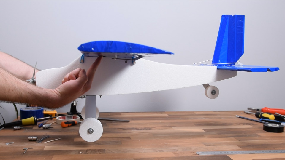
Nevertheless, let’s finish the assembly now. So, I connected everything as explained in the circuit diagram. On channel 1 is the rudder, channel 2 the elevator, channel 3 and 4 the ailerons, and on channel 6 the LED. I glued the LED on one side and the power switch on the other side.
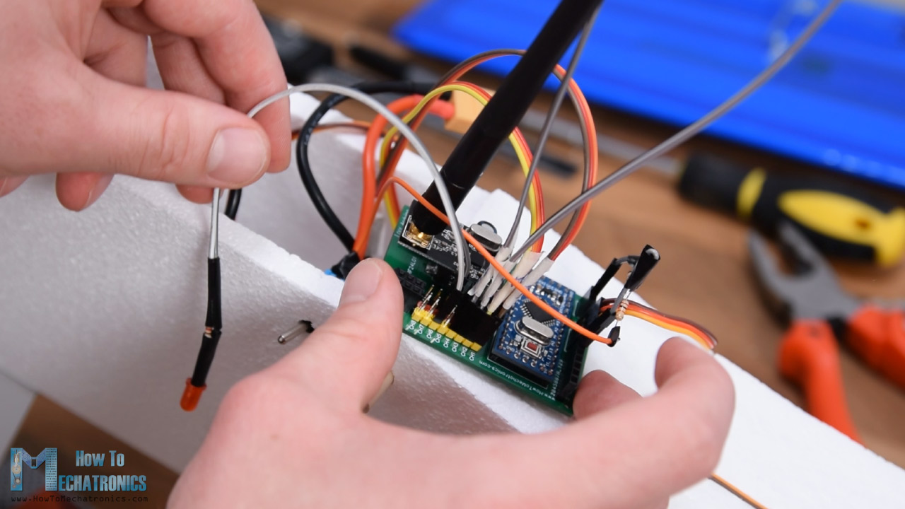
We can note here how the landing gear is attached to the airplane using the two bolts on the motor holder. In few words, I simple inserted the motor with the holder from this top opening, bolted in place as show earlier, and attached the landing gear as well. When inserting the holder, I also added some rubber bands so they can hold the battery in place.
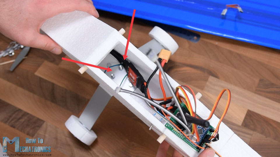
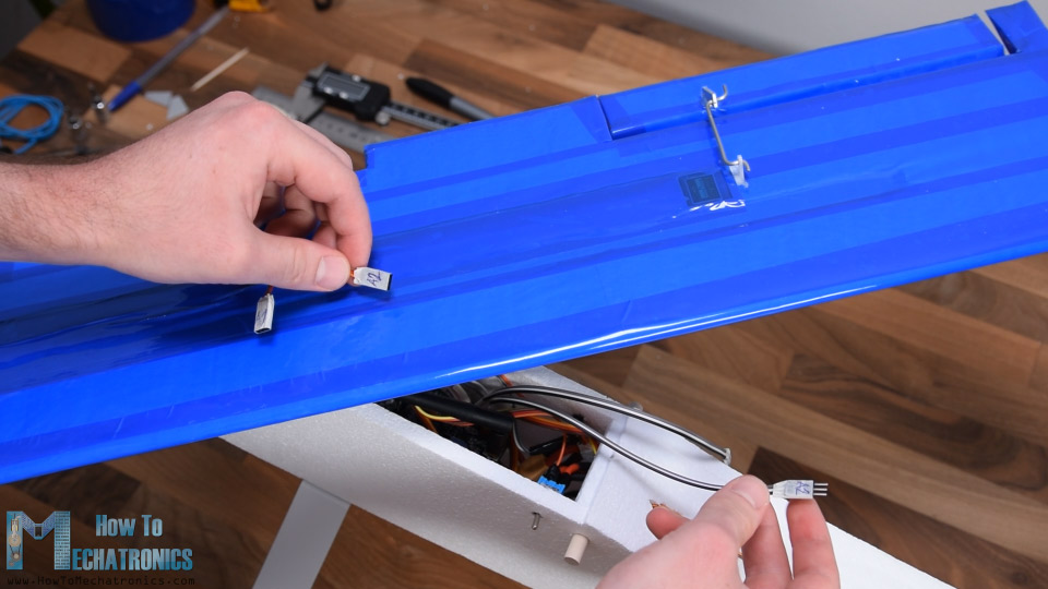
So, once I connected the battery to the ESC, I squeezed everything in. Finally, using the extension cables I can easily connect the wing ailerons to the receiver and then secure the wing to the fuselage.
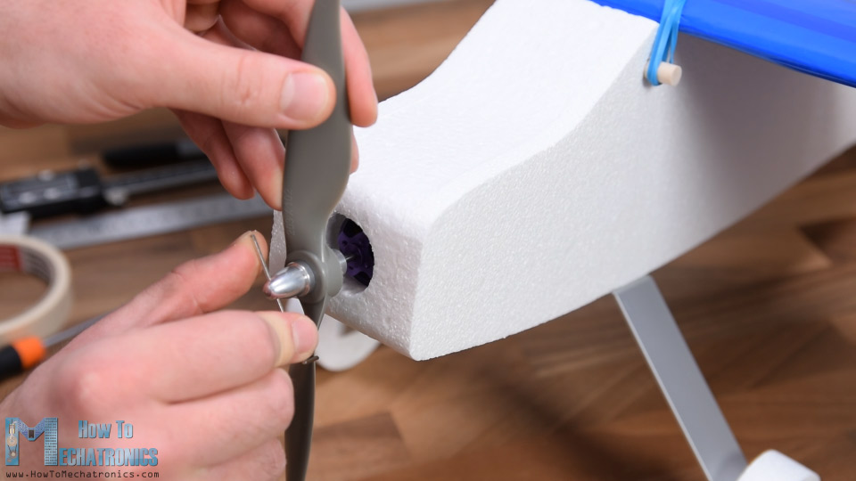
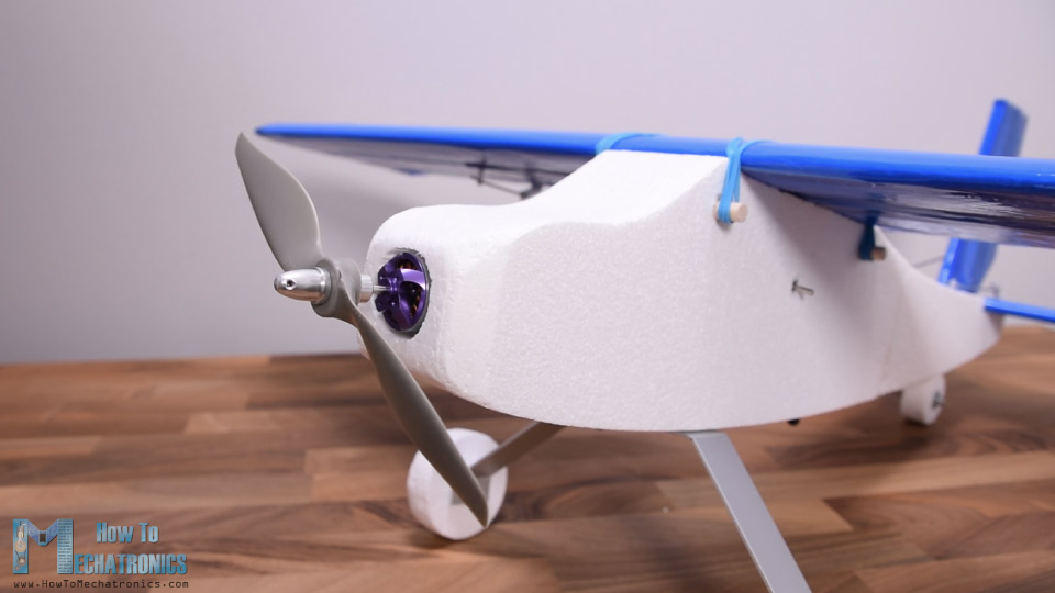
On the front, I attached the propeller to the motor and what’s left now is to check the CG or the center of gravity of the airplane.
The CG is probably the most important factor whether the airplane will fly well or fly at all.
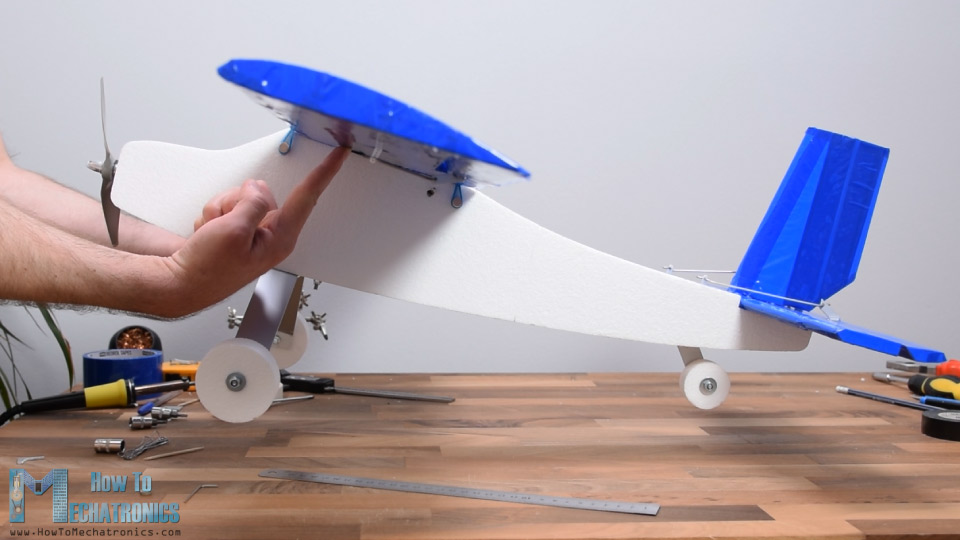
The airplane initially was tail heavy so I moved the battery to the front and added some weight (some bolts and nuts) and it got balanced.
That’s it, our Arduino based RC airplane is now done and we can go outside to try it out.
Testing the Arduino RC Airplane
Well, the first try or the maiden flight was not so cool. Especially after seeing the result of the crush.
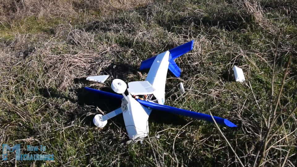
My conclusion here was that the airplane was still tail heavy and it felt like the motor didn’t have enough power. As I didn’t have another motor or propeller to try, I modified the nose of the plane to be a bit smaller, moved the motor more to the front so it has better airflow and also rounded the edges on the front. As for the structure I reinforced it with some wooden sticks and aluminum profiles that I glued in the inside area of the fuselage.
At the bottom of the electronics compartment I made two holes, one for the air to escape that comes from the front opening, and the other for getting the NRF24L01 antenna outside for having batter range.
Ok so here’s try number two. Again, almost the same thing, though it felt like it had better airflow or power now.
The fuselage broke again, which tells that this Styrofoam is pretty weak for this purpose. I made a new fuselage, and this time used a little bit of duct tape for reinforcing it.
Try number three. It looked promising but the terrain I have for takeoff is actually not good at all. The airplane started moving to the right, hit the edge of the road and broke again.
I repaired it and this time wrapped almost the entire fuselage with duct and packing tape. I should have done that much earlier as this gave the right strength to the fuselage and it didn’t break even after several more crushes.
The problem now was that after several crushes I broke all 4 propellers that I had so in this try I’m using a glued propeller. Of course, the propeller teared apart at takeoff.
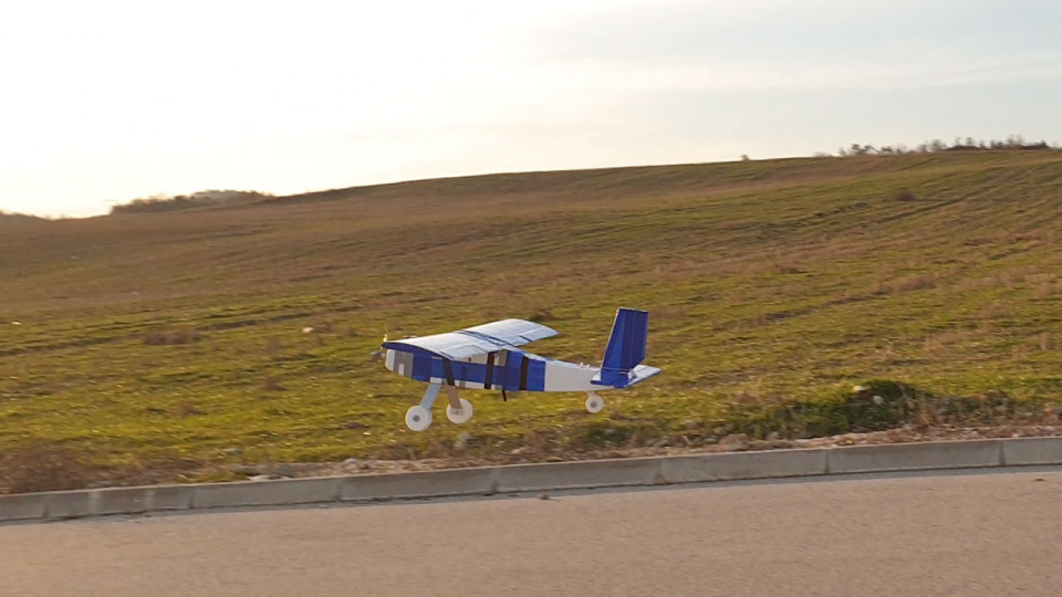
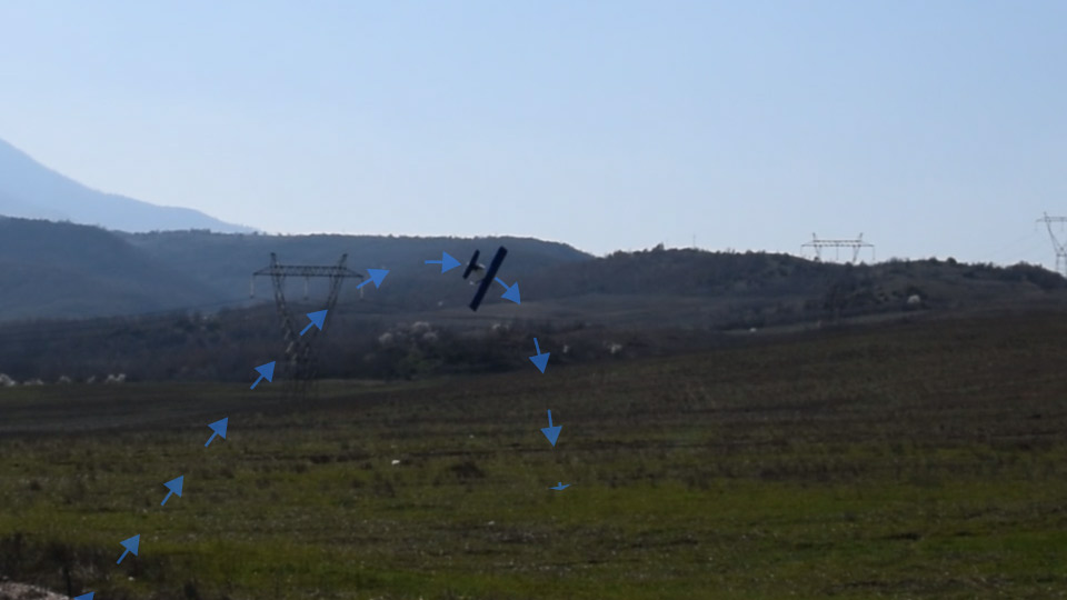
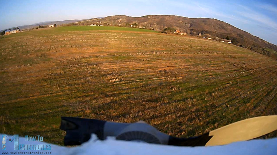
I tried with another glued propeller made out of two already broken propellers and this time I was actually lucky and the airplane finally took off properly.
Well the luck didn’t last for long as the propeller broke again in midair.
Nevertheless, as this was my first ever experience with flying an RC airplane, I guess I can consider this project successful, as I managed to prove the concept of making an entirely Arduino based system for controlling RC airplanes.
Other than that, we can note from the flight that the controls coming from the Transmitter are actually too harsh. That’s because the joysticks are not good at all for this purpose, they have small movement range and bad response.
In order to solve this, I added a feature to the program through which we can control the responsiveness of the controls using the right potentiometer on the transmitter. Also, I added a function through which we can trim the rudder using the left potentiometer.
Arduino RC Airplane Code
So finally, let’s take a look at the Arduino code of this Arduino based RC airplane and wrap this project up. The code is exactly the same as explained in the previous tutorial, for controlling servos and brushless motors using the NRF24L01 transceiver modules.
Here’s the complete code for this Arduino RC airplane project:
/*
   Arduino RC Airplane
   == Receiver Code =
  by Dejan, www.HowToMechatronics.com
  Library: TMRh20/RF24, https://github.com/tmrh20/RF24/
*/
#include <SPI.h>
#include <nRF24L01.h>
#include <RF24.h>
#include <Servo.h>

#define led 9

RF24 radio(3, 2);   // nRF24L01 (CE, CSN)
const byte address[6] = "00001";
unsigned long lastReceiveTime = 0;
unsigned long currentTime = 0;

Servo throttle;  // create servo object to control the ESC
Servo rudderServo;
Servo elevatorServo;
Servo aileron1Servo;
Servo aileron2Servo;


int throttleValue, rudderValue, elevatorValue, aileron1Value, aileron2Value, travelAdjust;
// Max size of this struct is 32 bytes - NRF24L01 buffer limit
struct Data_Package {
  byte j1PotX;
  byte j1PotY;
  byte j1Button;
  byte j2PotX;
  byte j2PotY;
  byte j2Button;
  byte pot1;
  byte pot2;
  byte tSwitch1;
  byte tSwitch2;
  byte button1;
  byte button2;
  byte button3;
  byte button4;
};
Data_Package data; //Create a variable with the above structure
void setup() {
  Serial.begin(9600);
  radio.begin();
  radio.openReadingPipe(0, address);
  radio.setAutoAck(false);
  radio.setDataRate(RF24_250KBPS);
  radio.setPALevel(RF24_PA_MAX);
  radio.startListening(); //  Set the module as receiver
  resetData();
  throttle.attach(10);
  rudderServo.attach(4);   // CH1
  elevatorServo.attach(5); // CH2
  aileron1Servo.attach(6); // CH3
  aileron2Servo.attach(7); // CH4
  pinMode(led, OUTPUT);    // CH6
}
void loop() {
  // Check whether we keep receving data, or we have a connection between the two modules
  currentTime = millis();
  if ( currentTime - lastReceiveTime > 1000 ) { // If current time is more then 1 second since we have recived the last data, that means we have lost connection
    resetData(); // If connection is lost, reset the data. It prevents unwanted behavior, for example if a drone jas a throttle up, if we lose connection it can keep flying away if we dont reset the function
  }
  // Check whether there is data to be received
  if (radio.available()) {
    radio.read(&data, sizeof(Data_Package)); // Read the whole data and store it into the 'data' structure
    lastReceiveTime = millis(); // At this moment we have received the data
  }

  // Controlling throttle - brushless motor with ESC
  throttleValue = constrain(data.j1PotY, 80, 255); // Joysticks stays in middle. So we only need values the upper values from 130 to 255
  throttleValue = map(throttleValue, 80, 255, 1000, 2000);
  throttle.writeMicroseconds(throttleValue);

  // Adjusting the servos responsiveness
  travelAdjust = map(data.pot2, 0, 255, 0, 25);

  // Elevator control
  elevatorValue = map(data.j2PotY, 0, 255, (85 - travelAdjust), (35 + travelAdjust));
  elevatorServo.write(elevatorValue);

  // Ailerons control
  aileron1Value = map(data.j2PotX, 0, 255, (10 + travelAdjust), (80 - travelAdjust));
  aileron1Servo.write(aileron1Value);
  aileron2Servo.write(aileron1Value);

  // Rudder trimming function
  if (data.j1PotX > 127) {
    rudderValue = data.pot1 + (data.j1PotX - 127);
  }
  if (data.j1PotX < 127) {
    rudderValue = data.pot1 - (127 - data.j1PotX);
  }
  // Rudder control
  rudderValue = map(rudderValue, 0, 255, (10 + travelAdjust), (90 - travelAdjust));
  rudderServo.write(rudderValue);

  // Monitor the battery voltage
  int sensorValue = analogRead(A3);
  float voltage = sensorValue * (5.00 / 1023.00) * 3; // Convert the reading values from 5v to suitable 12V i
  // If voltage is below 11V turn on the LED
  if (voltage < 11) {
    digitalWrite(led, HIGH);
  }
  else {
    digitalWrite(led, LOW);
  }
}
void resetData() {
  // Reset the values when there is no radio connection - Set initial default values
  data.j1PotX = 127;
  data.j1PotY = 80; // Motors stops // the central point of the joystick is not starting point for the throttle, its at value of 80 instead of 127
  data.j2PotX = 127;
  data.j2PotY = 127;
  data.j1Button = 1;
  data.j2Button = 1;
  data.pot1 = 1;
  data.pot2 = 1;
  data.tSwitch1 = 1;
  data.tSwitch2 = 1;
  data.button1 = 1;
  data.button2 = 1;
  data.button3 = 1;
  data.button4 = 1;
}Code language: PHP (php)
Description: I will just quickly explain the main functions of the code and for all other details you can check the previous tutorial. So, after receiving the data coming from the transmitter, we use the Joystick1 Y axis value for controlling the throttle of the airplane. We convert the values from 80 to 255 coming from the transmitter into values from 1000 to 2000 which are used for controlling the brushless motor.
For controlling the elevator, we use the Joystick2 Y axis value which we convert to values from 85 to 35. These values directly set the position of the servo motor in degrees. Right next to them we can note that we have the travelAdjust variables, which value depends on the position of the right potentiometer. We actually use that value to decrease the position or the movement of the servos although the joysticks will go to their maximum position.
The same principle is applied for controlling the ailerons and the rudder. Additionally, we use the data from the left potentiometer to adjust the neutral point of the rudder.
Lastly, using the analogRead() function and some math we control the battery voltage indicator LED.
So that’s it. I would like to hear your thoughts about this project in the comments section below, especially from you who have experience with building and flying RC airplanes. For those who are beginners and thinking of getting into this, I would suggest to check the FliteTest YouTube channel because it’s an amazing resource for learning about this RC world. I will put a link to it in the description.
I hope you enjoyed this project and learned something new. Feel free to ask any question in the comments section below and don’t forget to check my Arduino Projects Collection.
Thanks for sharing this i like it
there is one missing in this rc plane
its a gyroscope
and it will be awesome
thank you
Hello Dejan.
I´m new follower and it is very exciting planning to do the RC plane…. I´m just cheking all the information you have on the web site. I really thank you for sharing all your experience on this matter.
Regards from Mexico.
Jesus Guerrero
Hello Dejan,
How are you doing? I wanted to do this project for fun during this time at home and I wanted to ask a question. Can this plane stay up in the air for at least 2 minutes?
Yeah you can keep it if you use a high powered lipo battery
Hello, your project is great, I am in the process of supplying the elements, and I am only missing the GCODE files that I cannot download, do you have another download solution because ZLIB at home does not work. Pending. Thank you in advance. Best regards – Fernand
Hey, thanks! I’ve updated the post, please try again, it should work now.
Hi,
Hope you are doing well……
have two questions about the transmitter:
switch one is intended for switching on the Gyro MPU 6050 ….
has the switch two already assigned a function?
And can I also connect servos to the receiver that are more powerful and therefore require a little more current / Ah? Or should I better supply them with electricity?
I know I have a lot of questions …
Thank you
Greetings Wolfgang Rupp
Hey, the left switch activates MPU6050 and it replaces the outputs of the left joystick. With the right switch you can do whatever you want, the transmitter just sends its output either 0 or 1, so in your program you can do whatever you want with it.
Hey
thanks for the answer, I should have seen it in the sketch, but sometimes you overlook something (maybe with me due to age, grin)
Greetings Wolfgang Rupp
Hi Dejan,
Sketch works great, now I can switch four LEDs using the buttons,
it is really fun to work or experiment with your projects.
Receiver boards have come, now it is soldering ….
greeting
Wolfgang Rupp Germany
Hi,
great thanks for the help, i’m still familiarizing myself with the arduino commands, this is so versatile, arduino is a world in itself …………..
I’m still trying out the sketch with the new commands today, and then giving you feedback
Wish you a nice Sunday, here the sun is shining …
Lg
Wolfgang Rupp from Germany
PS. I can give you many tips for the RC motor pilot
Hello Dejan,
I hope you are doing well. is it possible to control the BLDC using a controller based on the HC-12 transmitter? I am trying to make a 3D printed “tank” and brushed gear motors are not cutting it so I want to use BLDC using some gear reductions to power the tank. would it be possible to control it this way?
Hey, thanks! You idea is sure possible. The HC-12 modules simply provide wireless communication between two Arduino, and then you can do whatever you want with the Arduinos.
Hello Dejan,
I need your help, please
I would like to switch RC Airplane on and off in your new project using the button LEDs on the plane (position lights)
Could you please give me the commands that I still have to enter in the Reciver Sketch to switch the buttons on the transmitter for the LEDs on and off ….
Thanks alot
greeting
Wolfgang Rupp
Hey, I’m not sure if I understood you well, but you want to turn on and off some additional LEDs on that you will add on the plane? If that’s what you are asking, you just simple use the digitalWrite() function to turn on or off the LED. You can use any of the free channels or even the Analog input channels.
Hello Dejan,
Thank you for your prompt reply,
yes that’s exactly what I want to do, using the 4 buttons on the transmitter, for example. turn an LED on or off.
Do not know how I can expand your sketch with the buttons, because I’m somehow on the tube …..
The first 5 Reciver boards arrived today, perfect,
ordered another 5 …….
Take a look at the channel on you tube: https: //www.youtube.com/channel/UCsM-eoJt17xnWMNNpwhf8Nw
his name is NumaVIG ……….
there you will find interesting information for your motor plane project,
which is very important for your project, the brushless motor has to point about 3-5 degrees upwards when mounting, and the wing profile is called Clark Y, very important for good flight characteristics, the wings should be about 3 degrees V-shaped to each other ….
When weighing out the model, the nose is tilted slightly downwards …
can give you a thousand tips, that used to be my job ….
Stay healthy,
Greetings Wolfgang Rupp from German
Yeah, those are all good points for making the plane better.
In order turn on and off LEDs you need a simple code in the loop() section, something like:
if(data.button1 == 1) { // with this line you check whether the button is pressed
digitalWrite(led1, HIGH); // LED on
}
else {
digitalWrite(led1, LOW); // LED off
}
Dear Dejan, I like your DIY project very much, because they are not only interesting, but also can learn a lot of scientific knowledge. My favorite is the plane, because it is the vehicle of the future, which can take us to complete the global travel. I hope you can explain more about aircraft
Hi Dejan,
I hope you are fine,
that’s a great project with the RC Airplane …..
I learned model building for flight and ship models, and often destroyed a model airplane, but over time it got better and better, my focus was on gliders from Graupner, e.g. Amigo or Cirrus with 3m wingspan …..
my receiver boards from JLCBCB should come this week then I can go on
I will write to you when the project is finished, your page is really great and I hope there are many more projects to come
Stay healthy
Greetings Wolfgang Rupp from Germany
Thank you!