If your work or hobby correlates with CNC machines or 3D printers, then understanding what G-code is and how it works is essential for you. So, in this tutorial we will learn the basics of the G-code language, what are the most important or common G-code commands and we will explain how they work.
What is G-code?
G-code is a programming language for CNC (Computer Numerical Control) machines. G-code stands for “Geometric Code”. We use this language to tell a machine what to do or how to do something. The G-code commands instruct the machine where to move, how fast to move and what path to follow.
In case of a machine tool such as lathe or mill, the cutting tool is driven by these commands to follow a specific toolpath, cutting away material in order to get the desired shape.
Similarly, in case of additive manufacturing or 3D printers, the G-code commands instruct the machine to deposit material, layer upon layer, forming a precise geometric shape.
How to read G-code Commands?
At first glance, when you see a G-code file, it might look a quite complicated but it is actually not that hard to be understood.
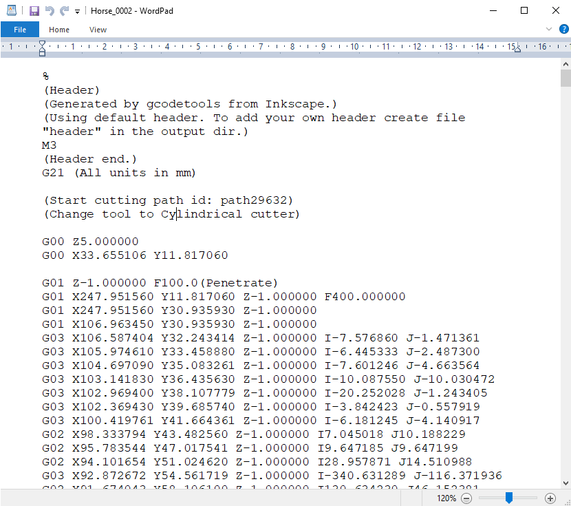
If we take a closer look at the code, we can notice that most of the lines have the same structure. It seems that the “complicated” part of the G-code are all those numbers we see, which are just Cartesian coordinates.
Let’s take a look at a single line and explain how it works.
G01 X247.951560 Y11.817060 Z-1.000000 F400.000000
The line has the following structure:
G## X## Y## Z## F##
- First is the G-code command and in this case that’s the G01 which means “move in straight line to a specific position”.
- We declare the position or the coordinates with the X, Y and Z values.
- Lastly, with the F value we set the feed rate, or the speed at which the move will be executed.
To wrap up, the line G01 X247.951560 Y11.817060 Z-1.000000 F400 tells the CNC machine to move in a straight line from its current position to the coordinates X247.951560, Y11.817060 and Z-1.000000 with speed of 400 mm/min. The unit is mm/min because if we take a look back at the G-code example image, we can see that we have used the command G21 which sets the units to millimeters. If we want the units in inches, we use the G20 command instead.
The most Important/ Common G-code Commands
So, now as we know how to read a line of G-code, we can take a look at the most important or commonly used G-code commands. We will learn how each of them work through several examples, and by the end of this tutorial we will be able to fully understand how G-code works, how to read, how to modify and even how to write our own G-code.
G00 – Rapid Positioning
The G00 command moves the machine at maximum travel speed from a current position to a specified point or the coordinates specified by the command. The machine will move all axis at the same time so they complete the travel simultaneously. This results in a straight line movement to the new position point.
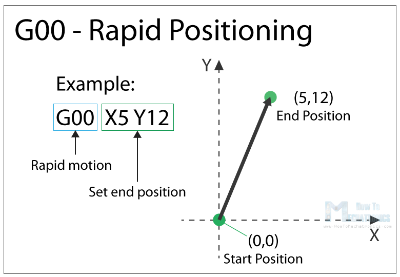
The G00 is a non-cutting movement, and its purpose is to just quickly move the machine to the desired position to begin some kind of job, like cutting or printing.
G01 – Linear Interpolation
The G01 G-code command instructs the machine to move in a straight line at a set feed rate or speed. We specify the end position with the X, Y and Z values, and the speed with the F value. The machine controller calculates (interpolates) the intermediate points to pass through to get that straight line. Although these G-code commands are simple and quite intuitive to understand, behind them, the machine controller performs thousands of calculations per second in order to make these movements.
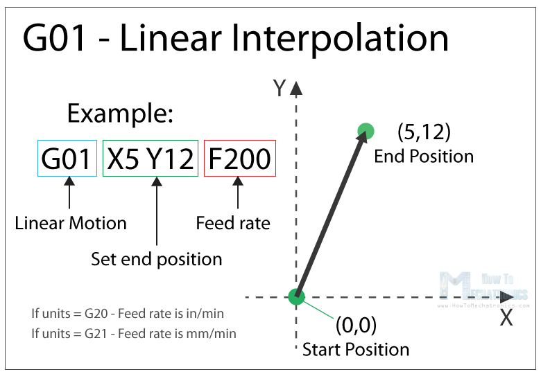
Unlike the G00 command which is used just for positioning, the G01 command is used when the machine is performing its main job. In case of lathe or mill, cutting material in straight line, and in case of a 3D printer, extruding material in straight line.
G02 – Circular Interpolation Clockwise
The G02 command tells the machine to move clockwise in a circular pattern. It’s the same concept as the G01 command and it’s used when performing the appropriate machining process. In addition to the end point parameters, here we also need to define the center of rotation, or the distance of the arc start point from the center point of the arc. The start point is actually the end point from the previous command or the current point.
For better understanding, we will add the G02 command after the G01 command from the previous example.
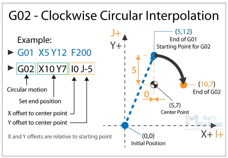
So, in the example first we have the G01 command which moves the machine to the X5, Y12 point. Now this will be the starting point for the G02 command. With the X and Y parameters of the G02 command we set the end point. Now in order to get to this end point using a circular motion or using an arc, we need to define its center point. We do that using the I and J parameters. The values of the I and J are relative to the starting point, or the end point of the previous command. So, to get the center point to the X5 and Y7, we need to make an offset of 0 along the X axis, and offset of -5 along the Y axis.
Of course, we can set the center point anywhere else, thus we will get a different arc which ends at the same end point. Here’s an example of that:
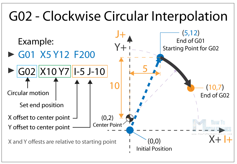
So, here we still have the same end point as the previous example (X10, Y7), but the center point is now at different position (X0, Y2). With this we got wider arc compared to the previous one.
See also: How to Setup GRBL & Control CNC Machine with Arduino
G00, G01, G02 Example – Manual G-code Programming
Let’s take a look at a simple CNC milling example using these three main G-code commands, G00, G01 and G02.
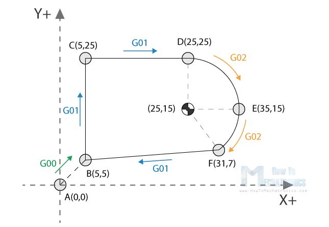
To get the toolpath for the shape shown in the image above we need to following G-code commands:
G00 X5 Y5                ; point B
G01 X0 Y20 F200          ; point C
G01 X20 Y0               ; point D
G02 X10 Y-10 I0 J-10     ; point E
G02 X-4 Y-8 I-10 J0      ; point F
G01 X-26 Y-2             ; point B
With the first G00 command, we quickly bring the machine from its home or initial position to the point B(5,5). From here we start with “cutting” at a feed rate of 200 using the G01 command. We can note here that for getting from point B(5,5) to the point C(5,25) we use values for the X and Y relative to the starting B point. So, +20 units in Y direction will get us to point C(5,25). Actually, this depends whether we have selected the machine to interpret the coordinates as absolute or relative. We will explain this in later section.
Once we reach the point C(5,25), we have another G01 command to reach the point D(25,25). Then we use the G02 command, a circular motion, to get to point E(35,15), with a center point (25,15). We actually have the same center point (25,15) for the next G02 command, to get to point F(31,7). However, we should note that the I and J parameters are different from the previous command, because we offset the center from the last end point or the point E. We finish the toolpath with another G01 command which gets us from point F(31,7) back to point B(5,5).
So, that’s how we can manually program the G-code for making this shape. Though, we need to note that this is not a complete G-code, because we are missing few more basic commands. We will make the complete G-code in a later example as we first need to explain those G-code commands.
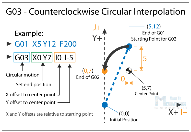
G03 – Circular Interpolation Counterclockwise
Just like the G02, the G03 G-code command defines the machine to move in circular pattern. The only difference here is that the motion is counterclockwise. All other features and rules are the same as the G02 command.
So, with these three main G-code commands, G01, G02 and G03 we can generate a toolpath for, literally, any shape we want. You might be wondering now how is that possible, but that’s actually an easy task for a computer and a CAM software. Yes, it’s true we can sometimes manually make a G-code program, but most of the time we do that with appropriate software which far more easier and safer.
Nevertheless, now explain few more important and commonly used commands and at the end make a real G-code example.
G20/ G21 – Units Selection
The G20 and G21 commands define the G-code units, either inches or millimters.
- G20 = inches
- G21 = millimiters
We need to note that the units must be set at the beginning of the program. If we don’t specify the units the machine will consider the default set by the previous program.
G17/ G18/ G18 – G-code Plane Selection
With these G-code commands we select the working plane of the machine.
- G17 – XY plane
- G18 – XZ plane
- G19 – YZ plane
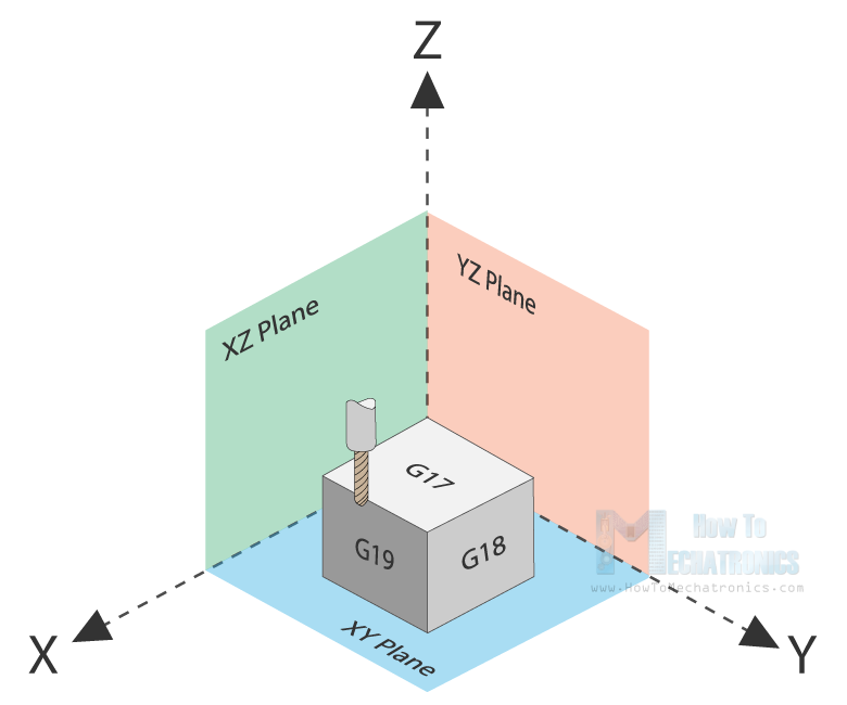
The G17 is default for most CNC machines, but the other two can be also used for achieving specific movements.
G28 – Return Home
The G28 command tells the machine to move the tool to its reference point or home position. In order to avoid collision, we can include an intermediate point with X, Y and Z parameters. The tool will pass through that point before going to the reference point. G28 X## Y## Z##
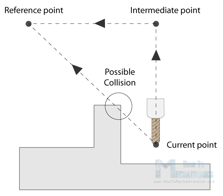
The home position can be defined with the command G28.1 X## Y## Z##.
G90/ G91 – Positioning G-code commands
With the G90 and G91 commands we tell the machine how to interpret the coordinates. G90 is for absolute mode and G91 is for relative mode.
In absolute mode the positioning of the tool is always from the absolute point or zero. So the command G01 X10 Y5 will take the tool to that exact point (10,5), no matter the previous position.
On the other hand, in relative mode, the positioning of the tool is relative to the last point. So if the machine is currently at point(10,10), the command G01 X10 Y5 will take the tool to point (20,15). This mode is also called “incremental mode”.
See Also
Arduino CNC Foam Cutting Machine
More Commands and Rules
So, the G-code commands we explained above are the most common ones but there are many more. There are commands like cutter compensation, scaling, work coordinate systems, dwell etc.
In addition to the G-code, there also M-code commands which are used when generating a real full-fledged G-code program. Here are few common M-code commands:
- M00 – Program stop
- M02 – End of program
- M03 – Spindle ON – clockwise
- M04 – Spindle ON – counterclockwise
- M05 – Spindle stop
- M06 – Tool change
- M08 – Flood colant ON
- M09 – Flood colant OFF
- M30 – End of program
In case of a 3D printer:
- M104 – Start extruder heating
- M109 – Wait until extruder reaches T0
- M140 – Start bed heating
- M190 – Wait until bed reaches T0
- M106 – Set fan speed
Some of these commands need appropriate parameters. For example, when turning on the spindle with M03, we can set the spindle speed using the S parameter. So, the line M30 S1000 will turn on the spindle at speed of 1000 RPM.
We can also note that many codes are modal, which means they remain in effect until cancelled or replaced by another code. For example, say we have a code for linear cutting movement G01 X5 Y7 F200. If the next movement is again a linear cutting, we can just type the X and Y coordinates, without the writing G01 at the front.
G01 X5 Y7 F200
X10 Y15
X12 Y20
G02 X5 Y5 I0 J-5
X3 Y6 I-2 J0
The same applies for the feed rate parameter F. We don’t have to include it in every line unless we want to change its value.
In some G-code file you can also see “N##” in front of the commands. The N word is simple to number the line or block of code. That can be helpful for identifying a specific line in case of an error in a huge program.
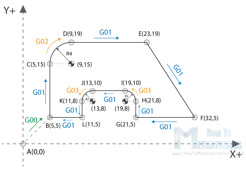
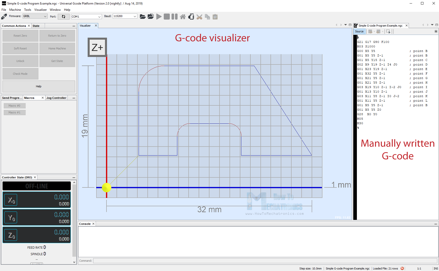
Simple G-code Program Example
Nevertheless, after reading all of this, now we are able to manually make a real, actual code. Here’s an example:
%
G21 G17 G90 F100
M03 S1000
G00 X5 Y5                 ; point B
G01 X5 Y5 Z-1             ; point B
G01 X5 Y15 Z-1            ; point C
G02 X9 Y19 Z-1 I4 J0      ; point D
G01 X23 Y19 Z-1           ; point E
G01 X32 Y5 Z-1            ; point F
G01 X21 Y5 Z-1            ; point G
G01 X21 Y8 Z-1            ; point H
G03 X19 Y10 Z-1 I-2 J0    ; point I
G01 X13 Y10 Z-1           ; point J
G03 X11 Y8 Z-1 I0 J-2     ; point K
G01 X11 Y5 Z-1            ; point L
G01 X5 Y5 Z-1             ; point B
G01 X5 Y5 Z0
G28  X0 Y0
M05
M30
%
Description of the G-code program:
- Code initialization. This character (%) is always present at the beginning and at the end of the program.
- Safety line: Set programming in metric system (all dimensions in mm), XY plane, absolute positioning and feed rate of 100 inches/min.
- Spindle on clockwise at speed of 1000 RPM.
- Rapid positioning to B(5,5).
- Controlled motion on the same position, but lowering the tool to -1.
- Linear cutting movement to position C(5,15).
- Clockwise circular motion to point D(9,19), with center point at (9,15).
- Linear cutting to point E(23,19).
- Linear cutting to point F(32,5).
- Same straight cutting to point G(21,5).
- One more straight cutting to point H(21,8).
- Counterclockwise circular interpolation to position I(19,10), with a center point at (19,8).
- Linear cutting to point J(13,10).
- Counterclockwise circular cutting to position K(11,8), with a center point at (13,8).
- Linear cutting to position L(11,5).
- Final linear cutting movement to position B(5,5).
- Rise up the tool.
- Go to home position.
- Spindle off.
- Main program end.
Here’s how this code looks ready to be sent to our CNC machine through the Universal G-code Sender software:
So, using these main G-code commands explained above, we managed to write our own fully-fledged G-code. Of course, this example is quite simple and for more complex shapes we definitely need to use a CAM software. Here’s an example of a complex G-code of a Horse shape:
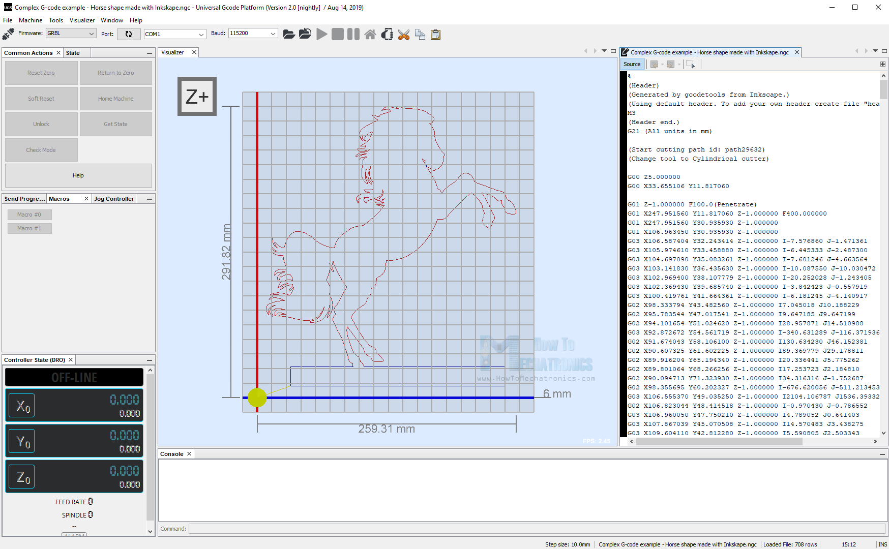
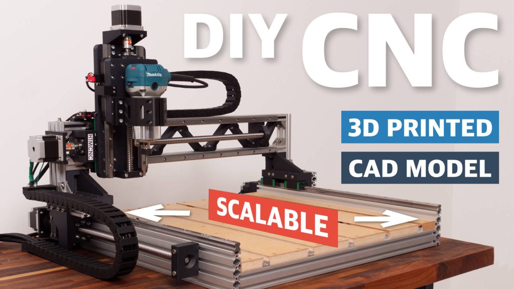
For comparison, this code has around 700 lines, but all of it generated automatically. The G-code was made using Inkscape as an example for my DIY Arduino CNC Foam Cutting Machine. Here’s how the shape came out:
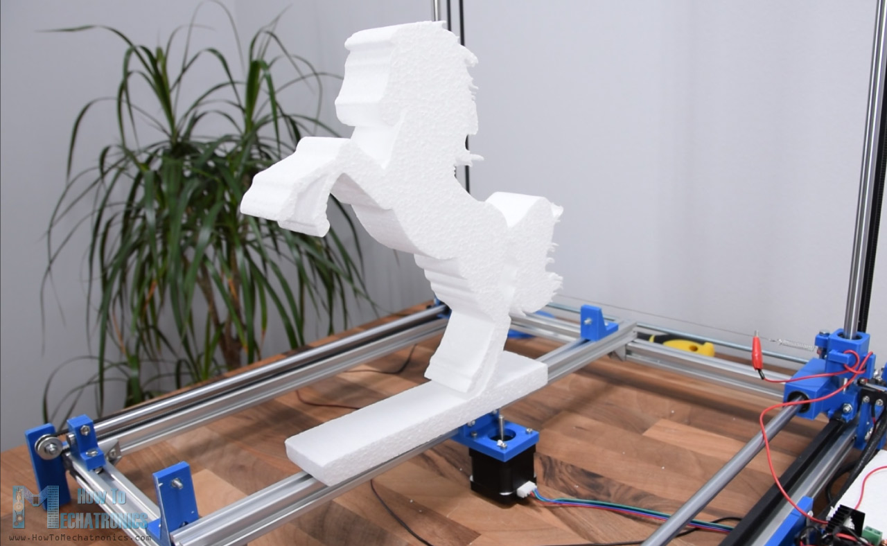
You can check my particular tutorial for more details about this machine.
Conclusion
So, we covered the basics of G-code, explained the most important and common G-code commands and manually made our own actual G-code. After all, I think understanding G-code is not that hard. Of course, there are so many other commands and features used in CNC machining or 3D printing that we should be aware of, but more on that in some other tutorials.
If you found this article useful, share it other CNC and 3D printing enthusiasts. Also feel free to ask any question in the comments section below.
EXCELLENT article, you went into just enough detail w/o “wandering off into the weeds”. I’m just getting into 3D printing and found this MOST helpful. I appreciate that you showed code with both written AND graphic explanation (some pick up better reading text, some prefer “pretty pictures”, so thanks for providing both). Clear enough that even an old FORTRAN and BASIC programmer (in a previous lifetime) could pick it up quickly. VERY well done, thanks much!
Maranatha
Appreciate… Very good explanation with simple sketches, code. etc.
It could be even better if M codes were explained similarly.
Hello Dejan,
Thanks for the G-code tutorial, I found it very helpful. I have tried to build a SCARA robot arm following your instructions in other project. So far, I can move the robot arm using your Processing code. But, I only see the servo motor openning and closing the gripper after I loaded the code to Arduino Uno card. When I select open or close slider, it has no movement. Any advice on how to make it work will be very much appreciated.
Hey, well I guess the serial communication is the problem, you don’t get the right string, or the Arduino can’t extract the right string and use that value to move the servo. It’s not the perfect way of communication that I did, but it worked at the time of making. But I guess there can be problems.
Thank a lot of the mystery explained in simple terms so even I can understand it😂
I found this article and the comments very useful for I am learning this all on my own. Thank you
Excellent article. I’m working through it in detail and think there are a couple of typos, but please put me right as appropriate. In your ‘simple cnc milling example’ the code
G00 X5 Y5 ; point B
G01 X0 Y20 F200 ; point C
G01 X20 Y0 ; point D
G02 X10 X-10 I0 J-10 ; point E
G02 X-4 X-8 I-10 J0 ; point F
G01 X-26 Y-2 ; point B
Lines 4 and 5 have two X values. I think the second value in each case should be a Y value i.e. X10 Y-10, X-4 Y-8
Yes, that’s right, thanks for the input!
In line 2
G21 G17 G90 F100
Safety line: Set programming in metric system (all dimensions in mm), XY plane, absolute positioning and feed rate of 100 inches/min.
You first set the machine to use mm – so shouldn’t F100 be in mm / minute?
Thanks, good article
Great introduction to G-code. Thanks
I am confused by the example for G00, G01, G02 Example line 5.
Should that Y position be Y-8 instead of X-8 ?
Yes, it was a typo, the example is updated now.
Hello. I really liked the article, thanks.
If you want to show how to make changes to the G-code, for example, speed, so that it changes from my desire, increases and then decreases
Thanks
Hello! Dejan。 I’m very glad to see your article again. As you said, G code is widely used. Although we don’t need to be proficient in it, we must understand its meaning, so that we can find out the reason more effectively when encountering problems. Thank you for this basic science course.