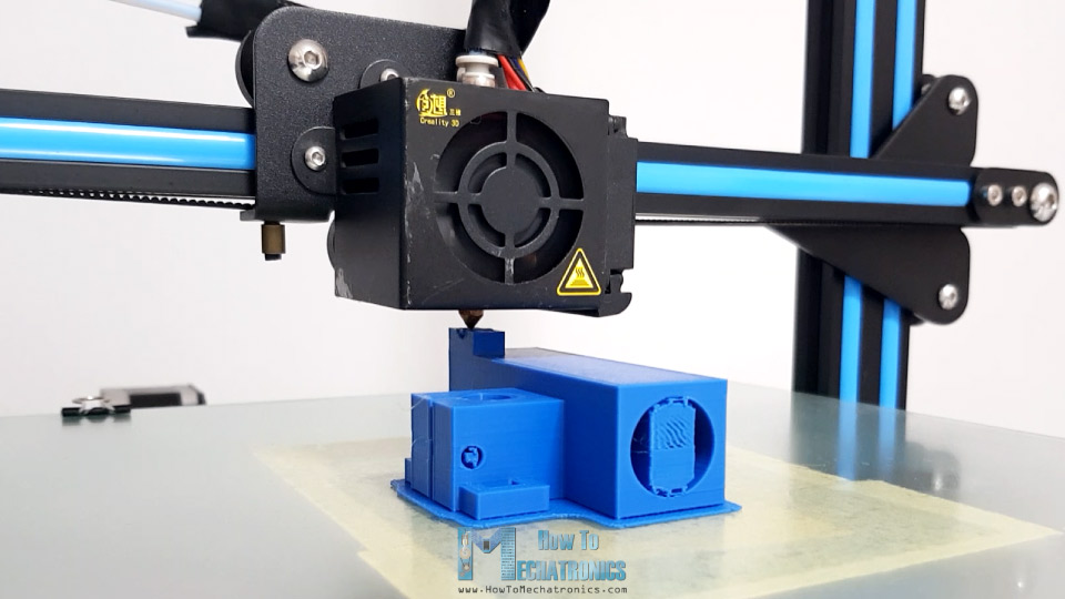
In this tutorial we will learn how to build an Arduino CNC foam cutting machine. This is a typical DIY CNC machine because it’s made out of simple and cheap materials, some 3D printed parts and it has an Arduino as a controller.
You can watch the following video or read the written tutorial below.
Overview
Instead of bits or lasers, the main tool of this machine is a hot wire, or a special type of resistance wire which gets really hot when current flows through it. The hot wire melts or vaporizes the foam when passing through it and so we can precisely and easily get any shape we want.
I said easily because building a CNC machine is actually not that hard. If you are a beginner and thinking about building your first DIY CNC machine, just stay tuned because I will explain how everything works. I will show you the entire process of building it, starting from designing the machine, connecting the electronic components, programming the Arduino and also explain how to prepare your shapes, make G-codes and control the machine using free, open source programs. So, let’s dive into it.
Arduino CNC Foam Cutting Machine 3D Model
To begin with, here’s the 3D model of this machine. You can download and the 3D model below.
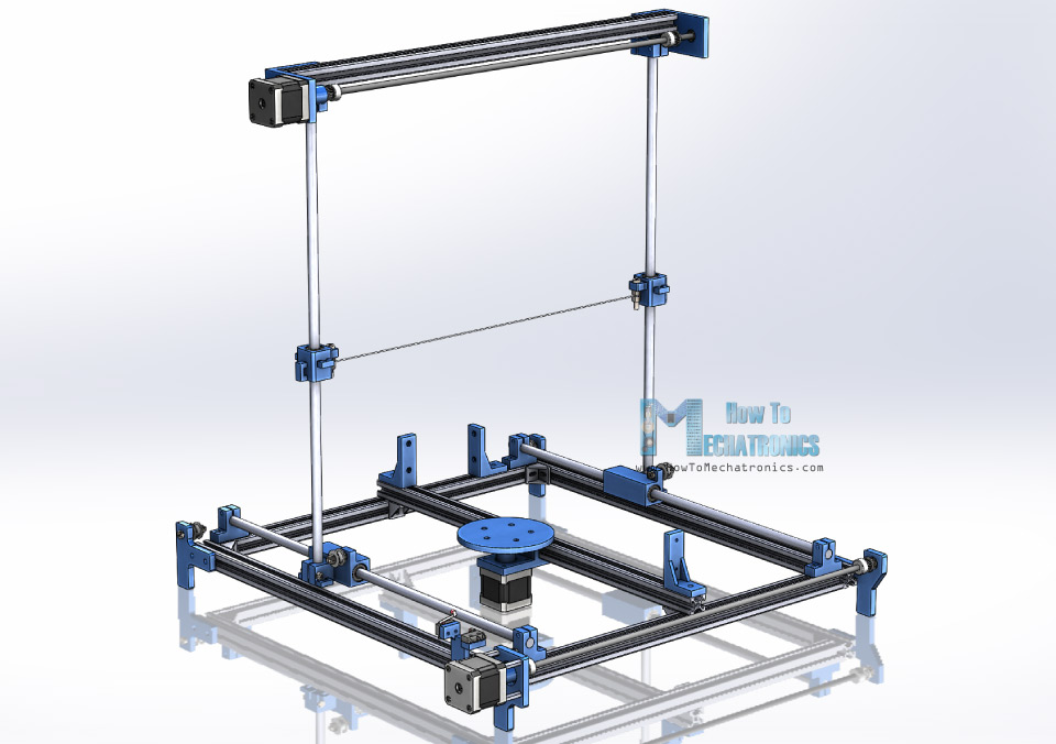
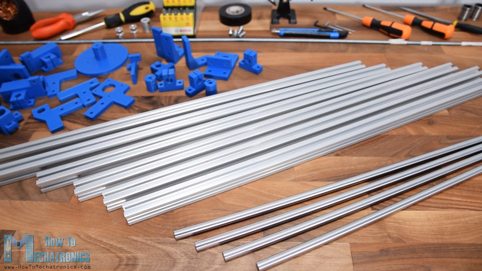
The base construction is made out of 20x20mm T-slot aluminum profiles. I chose these profiles because they are easy to use, we don’t have to drill any holes or something when assembling, and plus they are reusable, we can easily disassemble and use them for other projects. The motion of each axis is achieved by using linear bearings sliding on 10mm smooth rods. I used two rods for each axis.
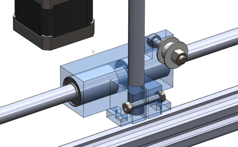
The sliding blocks might look a bit weird but they are designed in a way that they can be easily 3D printed as a single part while having multiple functions. So, for example, the X sliding block accommodates the two linear bearings, it holds the Y axis rod, it holds the pulley for the Y axis belt, as well as it has handles for attaching the X axis belt.
For driving the sliding blocks, we are using NEMA 17 stepper motors. Using a shaft coupler, a simple threaded rod, two pulleys and two belts we can evenly drive the two sliding blocks on each rail at the same time.
Here we can also notice that we have a third stepper motors which enables the machine to make 2.5D shapes and we will explain how that works a bit later in the video.
Overall, in terms of construction and rigidity the design is probably not that good, but I my point was to make a function machine with minimum parts possible and still to be able to get the job done.
3D Model and STL Download Files
You can get this 3D model, as well as the STL files for 3D Printing from Cults3D.
3D Printing
For 3D printing the parts I used my Creality CR-10 3D printer.
Note that some of the 3D printed parts need a bit of post-processing, or the supporting material should be removed before using.
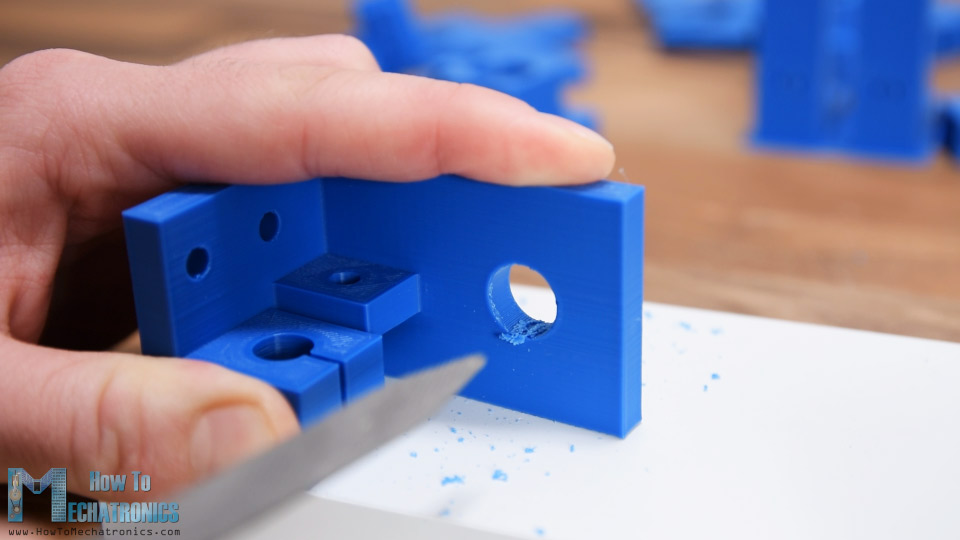
In some cases, I also had to use a rasp to remove the excess material, I guess due to bad support settings in the slicing software.
Assembling the CNC
Anyway, now I have all the materials ready so I can start assembling the machine.
Here’s a list of all main components used in this CNC machine. The list for the electronics components can be found below in the circuit diagram section of the article.
- 6x 20x20mm 500mm T-slot Aluminum Profiles …. Amazon / Banggood / AliExpress
- 4x 10mm Linear Rails Rods ………………….. Amazon / Banggood / AliExpress
- 6x T-slot profile corner brackets ………….. Amazon / Banggood / AliExpress
- 50x M5 nuts for T-slot Profiles………………. Amazon / Banggood / AliExpress
- 6x Linear bearings 10mm ……………………… Amazon / Banggood / AliExpress
- GT2 Belt + Tooth Pulley + Idler Pulley …. Amazon / Banggood / AliExpress + Idler Pulley
- 2x Bearing 5x16x5mm ……………………….. Amazon / Banggood / AliExpress ….. Note: In the video I’m using 6mm bearing as well as threaded rod and GT2 pulleys. Here I’m suggesting to use 5mm because these dimensions are more common and can be easily found. Therefore, in the STL download files, I also included two versions of the shaft couplers and the mounting brackets to mach these dimensions. So make sure you consider this when 3D printing those parts.
- Spacer Nuts ………………………………… Amazon / Banggood / AliExpress
- Spring assortment set……………….. Amazon / Banggood / AliExpress
- Hot wire ………………………………………. Amazon / AliExpress
- 2x 50cm threaded rod or any kind of rod 6 or 5mm diameter depending on the pulleys inner diameter
- Bolts and nuts from local hardware store: M3x30 x8, M4x25 x4, M4x30 x4, M5x10/12 x40, M5x15 x8, M5x25 x4, M5x30 x4
Disclosure: These are affiliate links. As an Amazon Associate I earn from qualifying purchases.
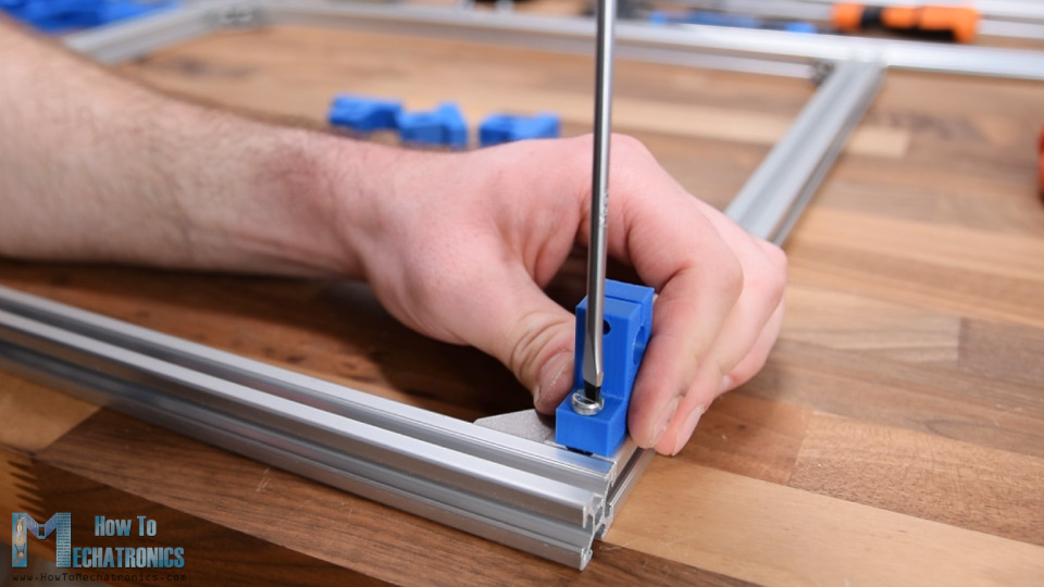
The T-slot aluminum profiles I had were 60cm long, so according to the 3D model, I cut each of them to size using a metal hand saw. Then using the corner brackets, I assembled the base frame. Next, I’m installing the shaft claps for the X axis. You see, working with T-slot profiles is so easy, we just need some M5 bolts and T-slot nuts for attaching all kind of things to them.
Next, I’m inserting the shaft rod through the clamps. While half inserted, we also need to add the X axis sliding block. We just put the two bearings in it and then insert them on the shaft. Now we can slide in the shaft to the other side and using a M4 bolt and a nut we can tighten the shaft in place. I repeated this process for the other side too.
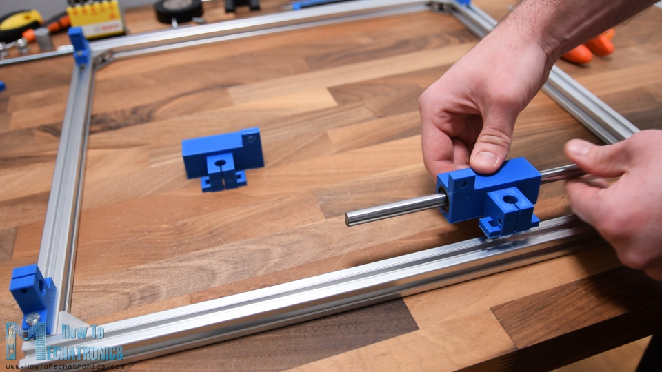
Next, we need to install the Y axes. For that purpose, first we need to insert the rods into the X axis sliding blocks, place them flush with the bottom of the part and secure them using M4 nuts and bolts. Then we can insert the Y axis sliding blocks. These sliding blocks use just a single linear bearing.
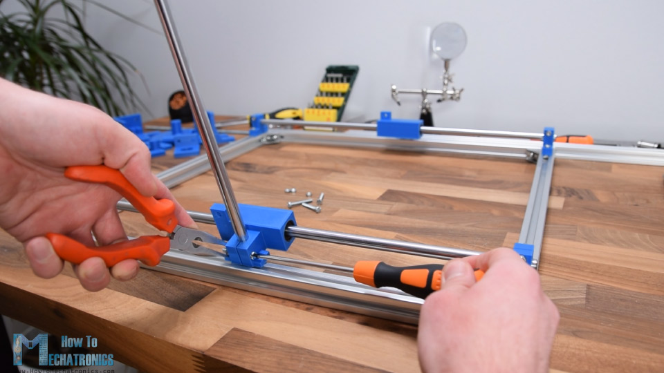
On top of the Y axis rods we need to attach the mounting brackets which will connect the two Y axis rods with a T-slot profile on the top. Again, we are using the same method for securing them to the rods. For attaching the T-slot profile to the mounting brackets, first I added 3 M5 bolts and T-slot nuts on them. Then I just slid the profile in, and fastened the bolts.
So, with this we have the main construction built and we can freely move in both the X and the Y axis.
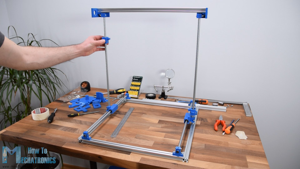
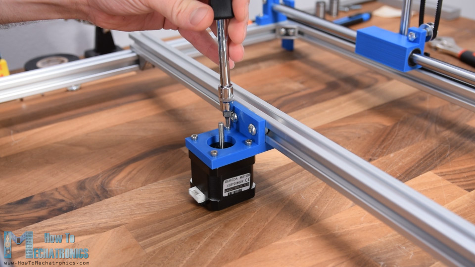
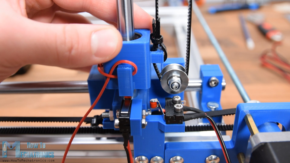
Next, I’m attaching the legs on the base frame. Again, it’s so simple to do that using the T-slot profiles. Once the legs are secured, I’m going to insert the first stepper motor for the X axis. In this case I’m using 20mm spacer nuts in order to distance the motors shaft so I’m able to place a belt pulley near the leg later on.
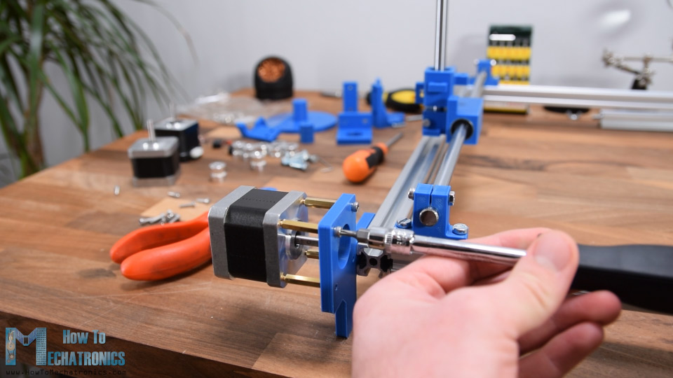
Ok so next I have a simple 6mm threaded rod which will drive the two belts at the same time. So first I cut it to size, placed a bearing with 6mm inner diameter on the opposite leg of the stepper and passed the threaded rod through it. Then I inserted a nut for securing the rod to the bearing and two toothed pulleys for the belts.
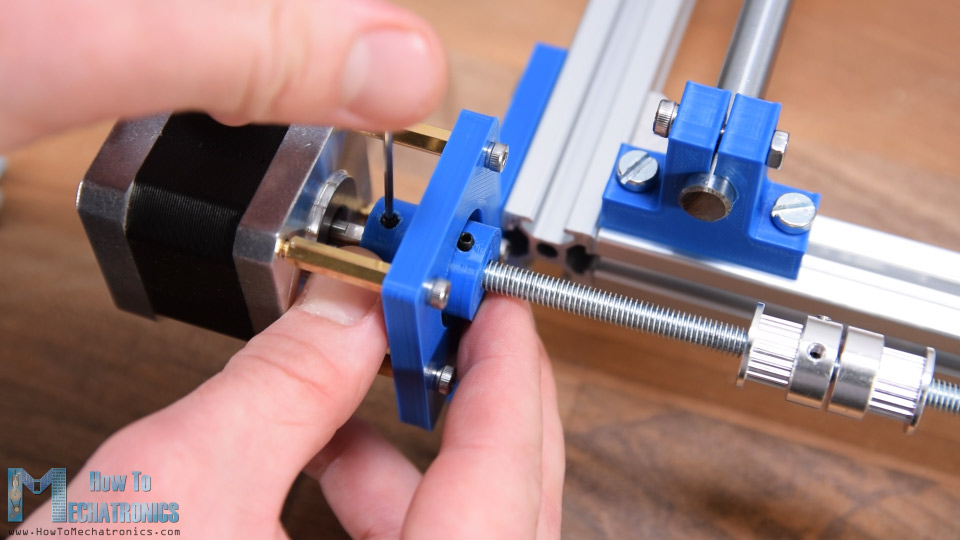
For connecting the threaded rod to the stepper motors, I 3D printed a shaft coupler with a 5 mm hole on the stepper side and 6 mm hole on the rod side. The shaft coupler has slots for inserting M3 nuts, and then using M3 bolts or grub screws we can easily secure it to the motors shaft and the threaded rod. Next, we need to position the pulleys in a line with the sliding blocks handles and also secure them with the grub screws.
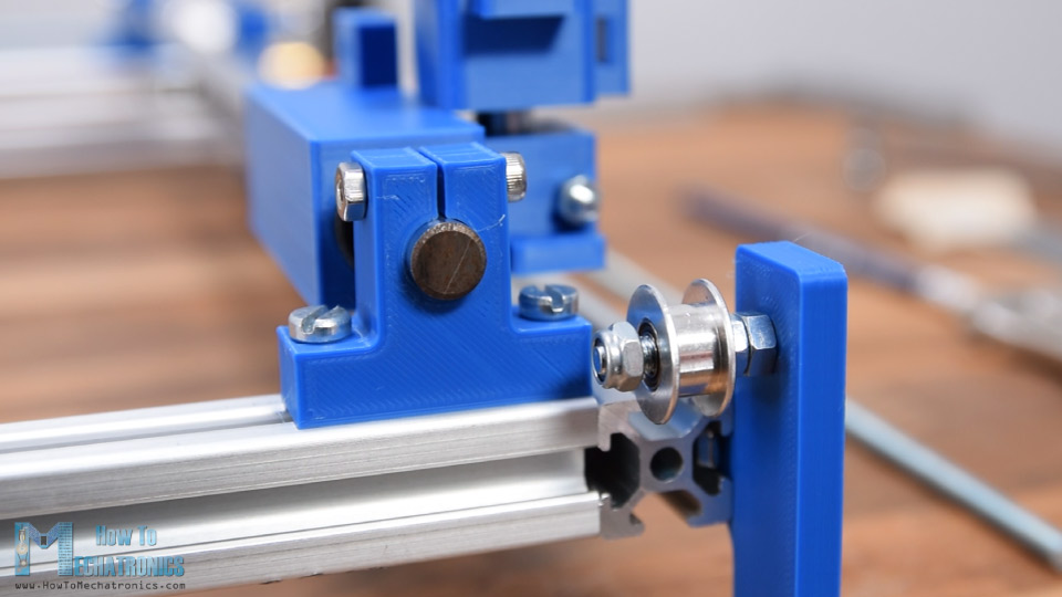
On the opposite side of the machine we can insert the two idler pulleys. I used some M5 bolts and nuts for that purpose.
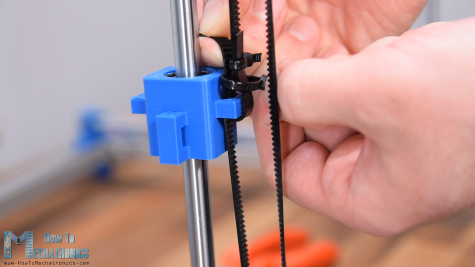
Ok so now we are ready to install the GT2 belts for the X axis. First, I inserted and secured the belt to the sliding block with a help of a zip tie. Then I passed the belt around the tooth pulley, on the other side around the idler pulley, cut it to the appropriate size and again secured it to the other side of the sliding block using a zip tie.
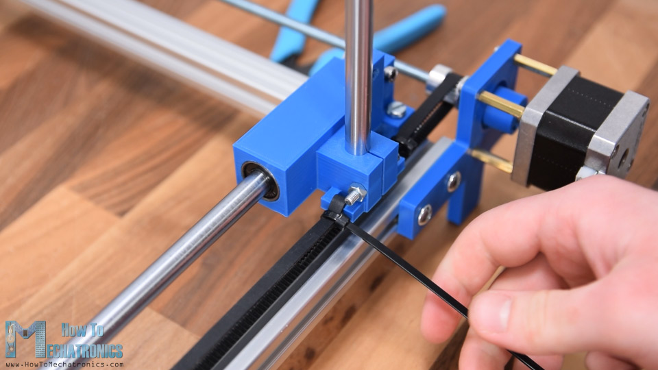
I repeated this process for the other side as well. When securing the other side, we must make sure that the two sliding blocks are on the same position on the X axis. For that purpose, we can simply move them to the end of the rails and so we can tighten the belt and secure it with a zip tie. With this the X axis sliding mechanism is done.
Related: DIY Pen Plotter with Automatic Tool Changer | CNC Drawing Machine
Next, with the same method we will assemble the Y axis mechanism. For securing the belt to the sliding block again we use zip ties. Here the sliding block has only one handle and in order to secure the belt, first I zip tied one end of the belt, then I stretched the belt to be tight enough and with another zip tie I caught both ends of the belt. Now I can just remove the previous zip tie and cut off the excess belt. As mentioned earlier, when securing the belt on the other side, we must make sure that the two sliding blocks are on the same position on the Y axis. With this the Y axis mechanism is also done.
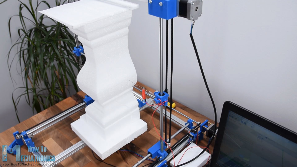
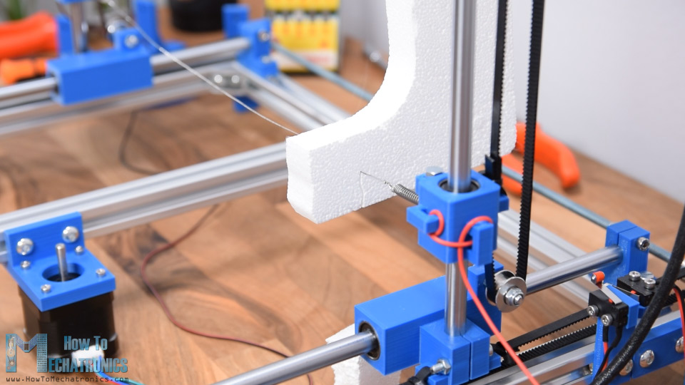
Next, I will attach one more T-slot profile across the X-axis. This profile will serve for attaching the 3rd stepper motor to it as well as for placing the foam pieces on it. With the 3rd stepper motor we can make 2.5D or actually three-dimensional shapes with this machine, like for example the chess piece.
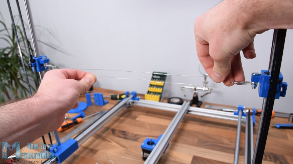
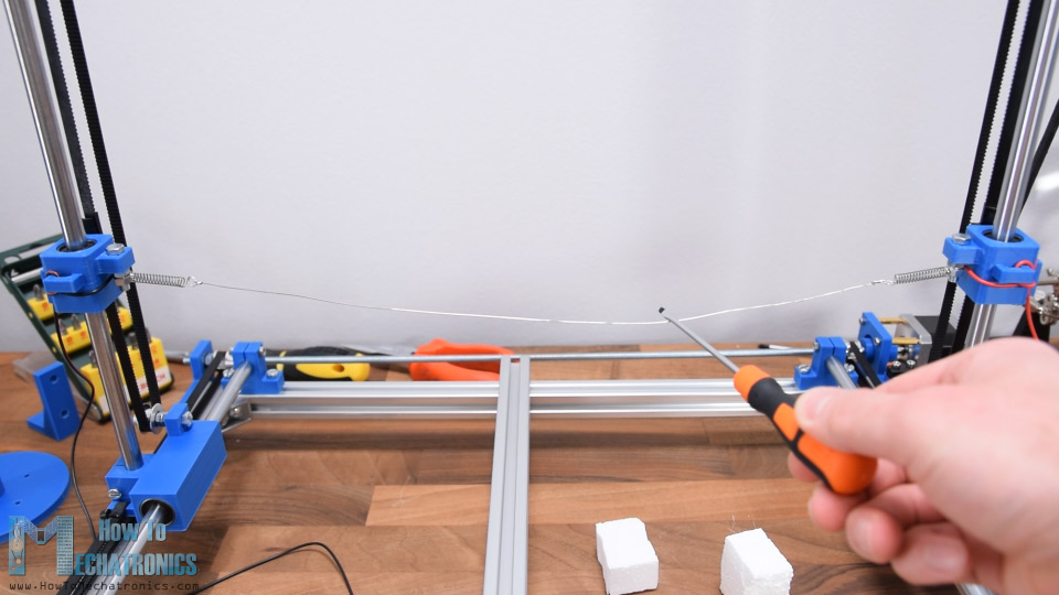
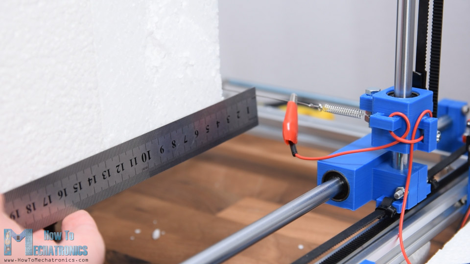
All right, so next we need to install the resistance wire. This wire needs to be able to withstand high heat while maintaining uniform temperature across its length. That’s usually Nichrome wire or a stainless-steel fishing wire which are actually inexpensive and easy to get. In order to work properly, the wire needs to be tensioned between the two towers or sliding blocks and here’s how I did it. I attached M5 bolts on both sliding blocks and added small extension springs to them.
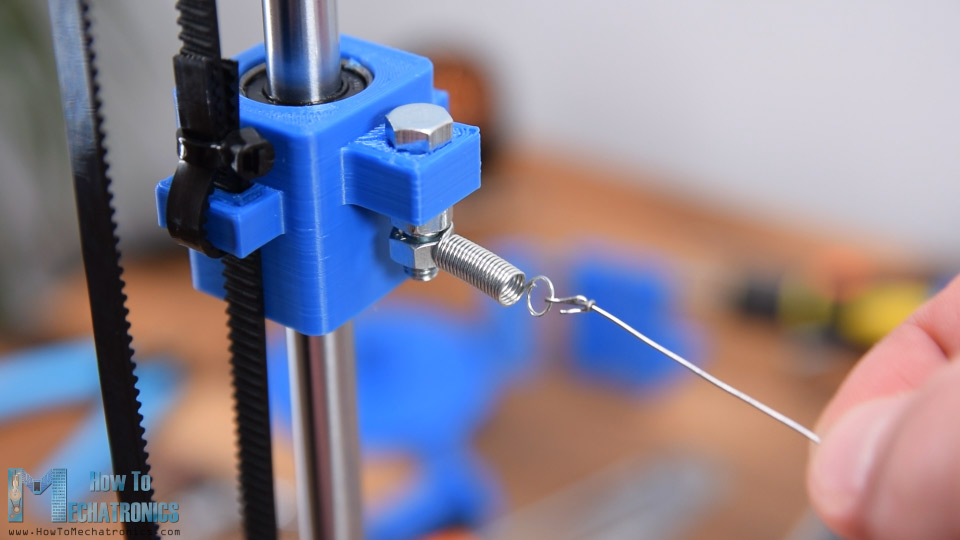
Then I simply attached the wire to the springs. I tensioned the wire as much as the springs allowed. The wire needs to be tensioned like this with springs because when it will get hot it will also extend its length and so the springs will be able to compensate for that.
Ok, so next we can connect the resistance wire with electrical wires. We will use DC power so the polarity doesn’t matter, it’s just important a current to flow through the wire in order to get hot. Here make sure your electrical wire is tick enough in order to support current draws of around 3 to 5 amps. In my case I’m using 22-gauge wire but I would suggest 20- or 18-gauge wire just for sure.
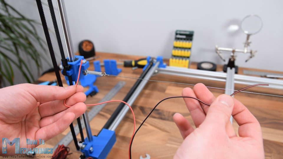
Initially I attached the electrical wire between the two nuts, and so the current could pass through the coil to the resistance wire. This actually didn’t work really well and I will show you why in a minute. I conducted the wire through the handles of the sliding block in order to stay neat and away from the hot wire.
Next, we need to install the CNC machine end-stops or limit switches. These micro limit switches have 3 connections, Ground, normally open and normally closed connection. Initially I connected them to Normally Open connections but after con
ducting some tests I switched to normally closed connection because in that way the machine works more stable.
The problem is the electrical noise generated while the CNC machine works which falsely triggers the switches like they are pressed and causes the machine to stop working.
Arduino CNC Foam Cutter Circuit Diagram
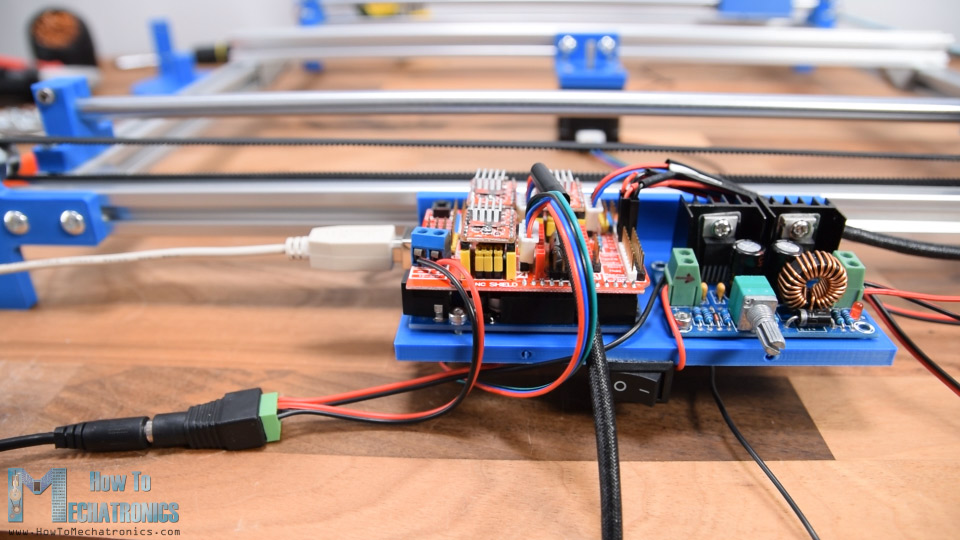
Next, we can connect the cables of the stepper motors and then see how to connect all electronic components. Here’s a circuit diagram of how everything needs to be connected.
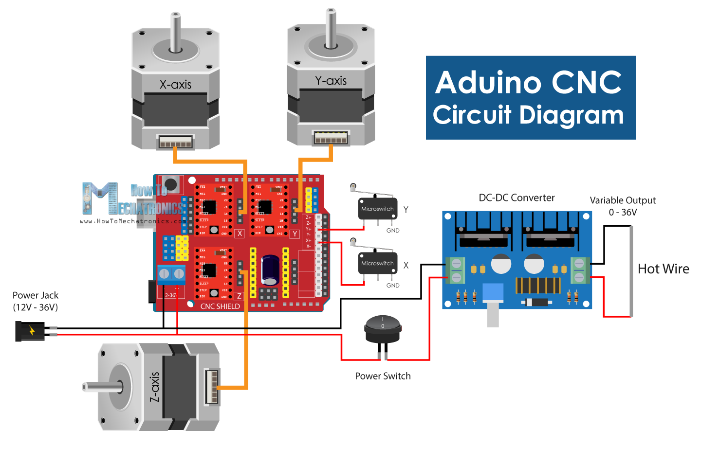
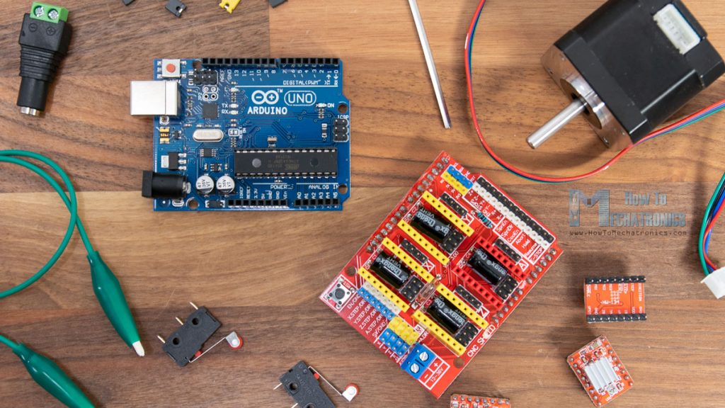
Of course, the brain of this CNC machine is an Arduino board. Along with it we also need an Arduino CNC Shield, three A4988 stepper drivers and a DC to DC converter for controlling the temperature of the hot wire.
You can get the components needed for this project from the links below:
- Stepper Motor – NEMA 17………… Amazon / Banggood / AliExpress
- A4988 Stepper Driver……………….… Amazon / Banggood / AliExpress
- Arduino CNC Shield …………………….. Amazon / Banggood / AliExpress
- Arduino Uno……………………………..… Amazon / Banggood / AliExpress
- DC-DC Converter ………………………… Amazon / Banggood / AliExpress
- Limit Switch ………………………………….. Amazon / Banggood / AliExpress
- DC Power Supply ………………………… Amazon / Banggood / AliExpress
Disclosure: These are affiliate links. As an Amazon Associate I earn from qualifying purchases.
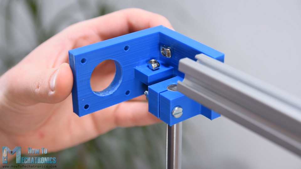
I 3D printed a stand for the electronics components which I secured it to one side of the T-slot profile. Using M3 bolts first I secured the Arduino board to the stand and then inserted the Arduino CNC shield on top of it.
Next, we need to select the resolution at which the stepper drivers will drive the motors using some jumpers. In my case I chose 16th step resolution by adding three jumpers to each driver and so the steppers will have smoother movements.
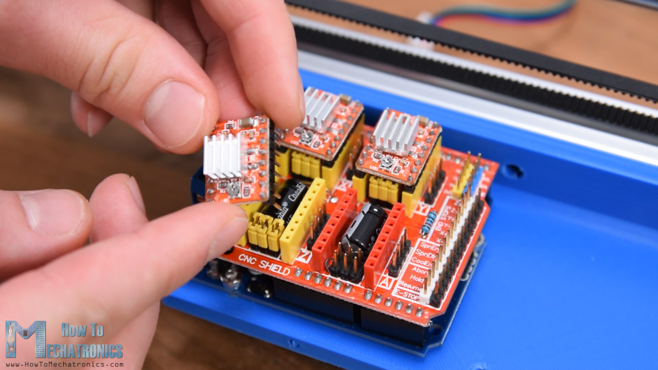
When placing the drivers make sure their orientation is correct, the small potentiometer can be an indicator for that which should be oriented to the bottom side of the shield.
I continued with securing the DC converter in place. Then I connected the three stepper motors to the Arduino CNC shield, as well as the two limit switches to the X+ and Y+ end stop pins. For powering the machine, I will use 12V 6A DC power supply. The Arduino CNC shield can actually work from 12 to 36 volts and also the particular DC converter that I use can work with the same voltages. On the input of the DC Converter I added a switch so I can turn on and off the hot wire separately. On the output of the DC converter I simply connected the two wires from the two ends of the resistance wire. Finally, we can connect and power the Arduino through the USB port and power the Arduino CNC shield and the stepper motors through the DC power plug.
All right, so now it’s time to test the machine whether it’s working properly and I will start with the hot wire. You can see here I have 0 volts at the DC converter input, and once I turn on the switch, I get 12V on the input. Then on the output of the DC converter again, we have zero volts but as we start turning the potentiometer, we can adjust the output voltage from 0 to 12V and so the current flow through the hot wire and untimely its temperature.
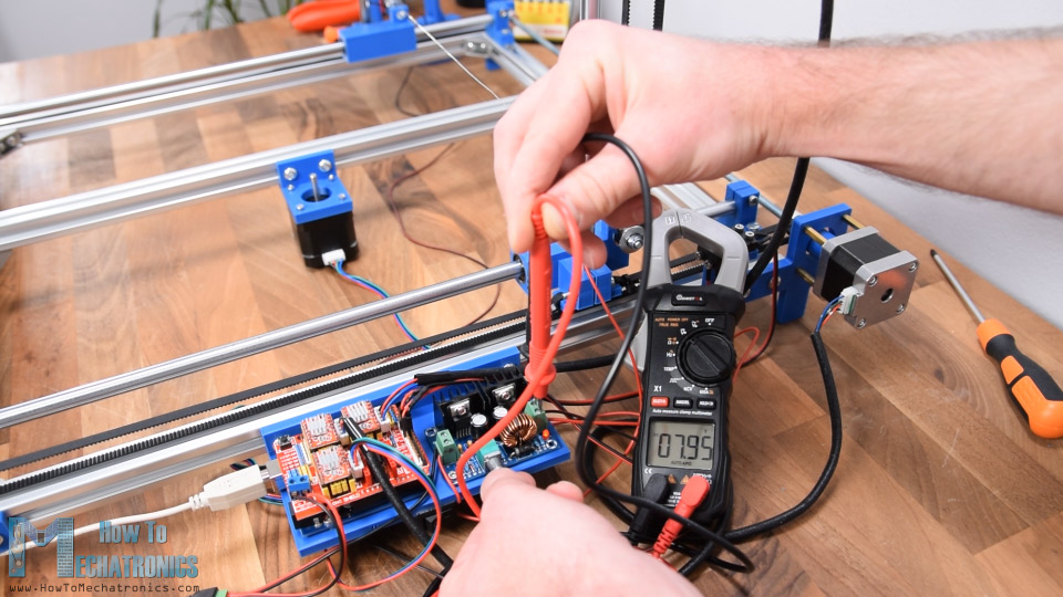
The best way to test at what voltage you should set the output of the DC converter is by trying to cut through some foam piece. The hot wire should be able to cut through the foam without much resistance and bending.
However, after the initial testing, you can see what happened to my hot wire. It extended due to the heat and the springs which should have compensated for that didn’t do their job.
Actually, the springs lost their functionality due to overheating, because with this configuration the current was flowing through them as well.
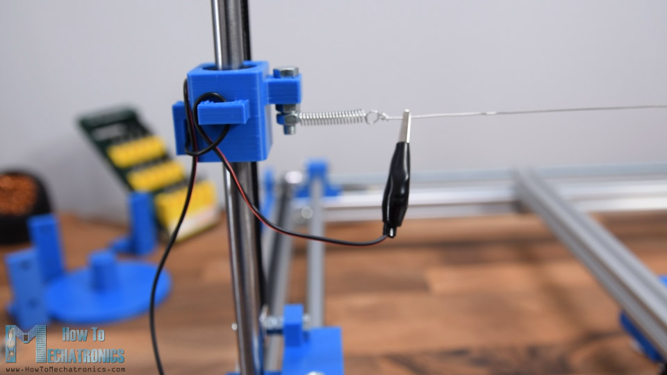
So, I replaced the old springs with new ones, and now I bypassed the springs by connecting the electrical wires directly to the resistance wire with the help of some alligator clamps.
Software for Arduino CNC Machines
Ok, so now it’s time to give live to this machine and make it a real CNC machine.
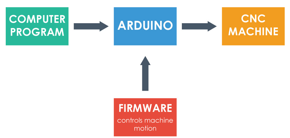
For that purpose, first we need to upload a firmware to the Arduino which controls the motion of the machine. Most popular choice for DIY CNC machines is GRBL firmware.

It’s open source and we can download it from GitHub.com. Once we download it as a zip file, we can extract it, copy the “grbl” folder and paste it into the Arduino library directory. Then we can open the Arduino IDE and from File > Examples > grbl choose the grblUpload example. Now we need to select the Arduino board that we are using, Arduino UNO, and select the COM port to which our Arduino is connected and finally upload this sketch to the Arduino. Once uploaded, now the Arduino knows how to read G-codes and how to control the machine according to them.
Next, we need some kind of interface or a controller which will communicate and tell the Arduino what to do. Again, I’m choosing an open source program for that purpose and that’s the Universal G-Code Sender.
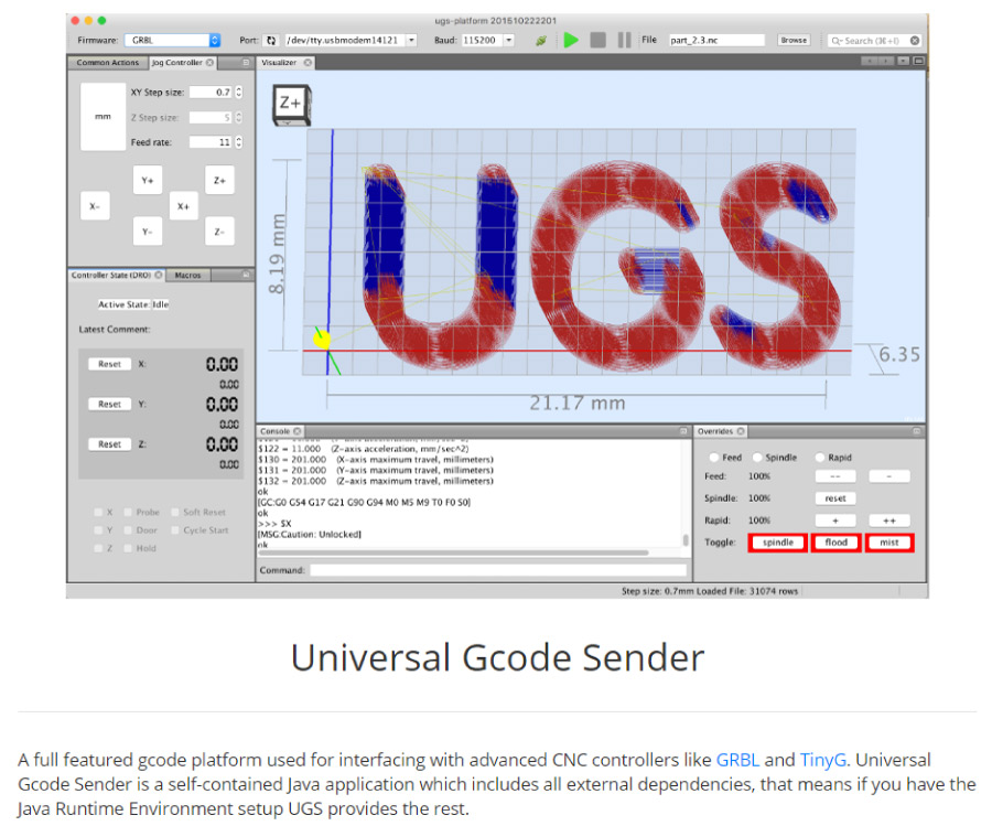
I downloaded the 2.0 Platform version. To run the program, we need to extract the zip file, go to the “bin” folder and open any of the executable ugsplatfrom files. This is actually a JAVA program, so in order to be able to run this program first we need to install JAVA Runtime Environment. We can also download this for free from its official website.
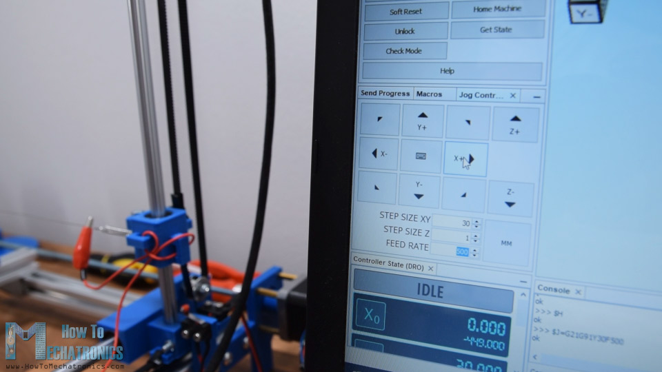
So, once we open the Universal G-Code Sender program first we need to run the Setup wizard in order to configure the machine.
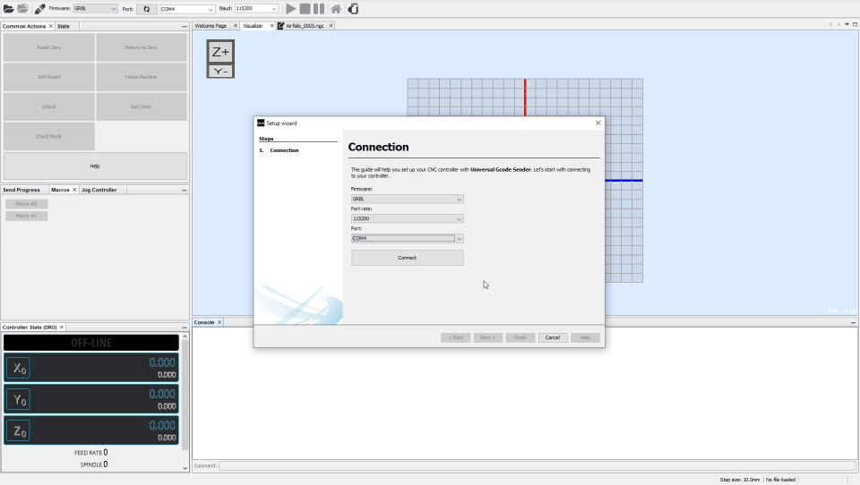
Here we need just to select the proper Port and connect the program to the Arduino. Once the connection is established, we can check the direction of moving of the motors by clicking the buttons. If needed we can reverse the direction. I chose the positive movements to go from the home position where the limit switches are located to the other sides.
Next, we need to calibrate the steps of the motors in order to achieve correct and accurate movements. As we selected 16th step resolution on the drivers, and the motors have 200 physical steps, that means it will take 3200 steps in order the motor to make full 360 degrees movement. Now depending on the transmission type, or in this case the size of the pulleys, we need to calculate the number of steps the motor needs so the machine moves 1mm. The default value here is set to 250 steps per mm. So, once we click one of the these move buttons the motor will make 250 steps.
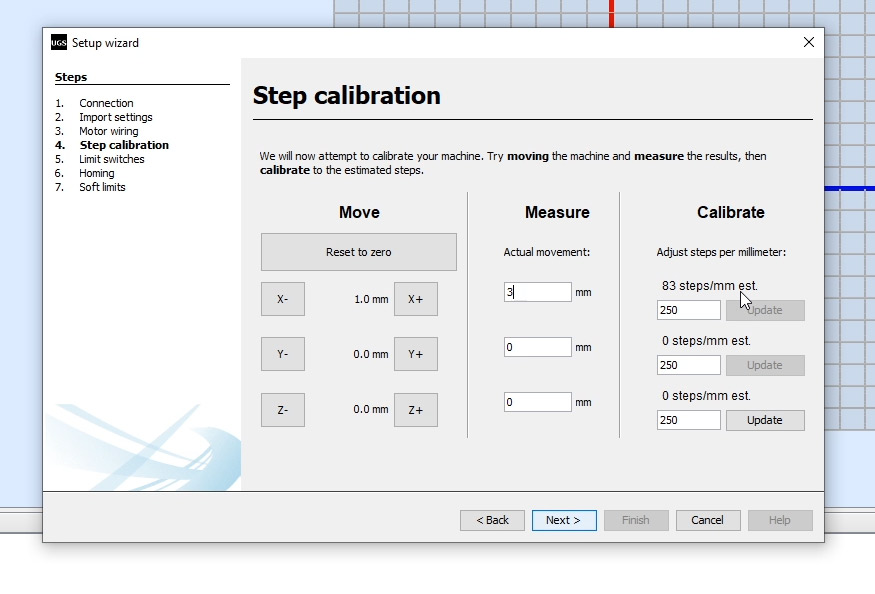
Now in reality, using a ruler we measure the actual movement the machine made and we enter that number here in the program. According to this, the program will calculate and tell us to that value we should change and update the steps/mm parameter. In my case that’s 83 steps/mm. As for the Z axis, I set it to 400 steps/mm, or that means a value 1mm for the Z axis will make a rotation of 45 degrees.
Next, we need to check whether the limit switches work properly. Depending whether we have connected them NO or NC we also can invert them here. Just like I said before, NC connection worked better for me. Anyway, here we need to notice that we need to turn off the Z axis limit switch as we don’t have one in our machine. If we don’t turn it off, we won’t be able to home the machine. In order to do that we need to go the grbl folder in the Arduino library, and edit the config.h file.
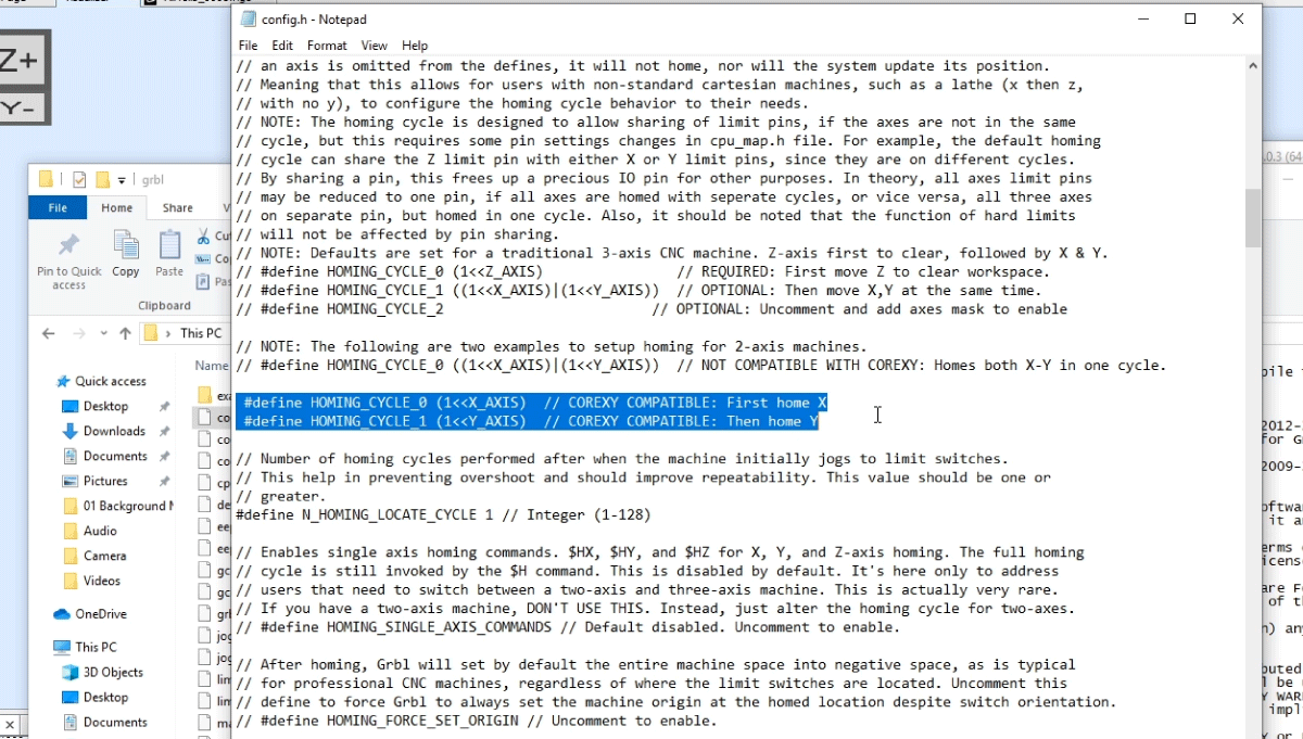
Here we need to find the homing cycle lines and comment the default set for 3 axis CNC machine and uncomment the setup for 2 axis machines. Now we need to save the file and reupload the grblUpload example to the Arduino. Note that you should probably restart the programs again in order everything to works properly.
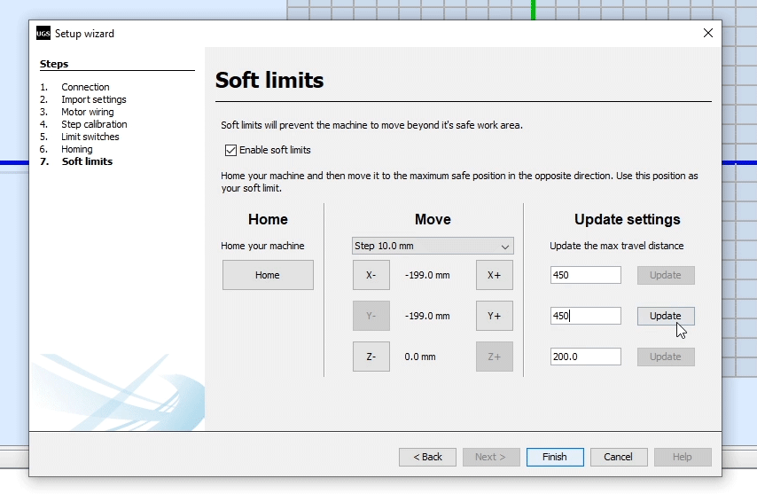
All right, so next we can try to home the machine using the Try homing button. When clicked the machine should start moving toward the X limit switch, and once pressed, it will start moving the Y axis. If needed we can change the limit switches directions. At the end of the setup wizard we can set Soft Limits which actually limits the maximum distance the machine can travel in each direction. In my case that’s 45x45cm.
Ok so now the program is ready to work. Before each use, you should always Home the machine and then you can do anything you want. First, I would suggest to play around and test the Jog controller or manually move the machine around. Also, at this point you should try to cut some foam pieces in order to find out what feed rate or speed of movement will be the most suitable for you.
So, you should play around with both the hot wire temperature and the feed rate in order to figure out what will get you the most clean and precise cuts on your foam pieces.
Generating G-code for the CNC Machine
Finally, what’s left in this video is to take a look how to prepare the drawings so the CNC machine can make shapes of out them. For that purpose, we need a vector graphics software, and again, I chose an open source one, and that’s Inkscape. You can download it from its official website for free.

I will show you two examples how to prepare the G-code for the Arduino CNC machine using Inkscape. So first we should set the page size to the size of our working area and that’s 45x45cm. For the first example I downloaded and image of the Arduino logo and imported into the program. Using the Trace Bitmap function, we need to convert the image to vector format.
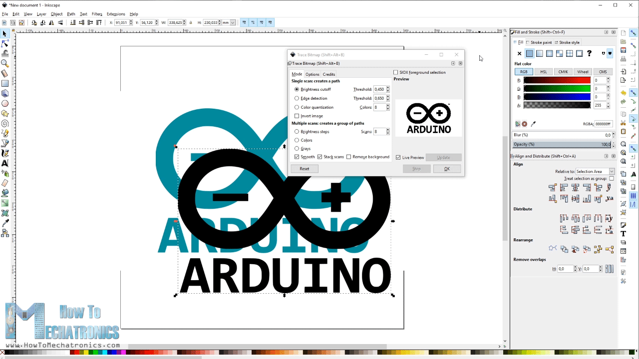
Now in order to be able to cut this shape with the hot wire, we need to make the shape to be a continuous path. That’s because the hot wire is always present in the working area, it cannot be raised like for example a bit or turned off in case of a laser, while traveling from one to other letter or shape. So therefore, using simple squares I connected all separate pieces together. We do that by selecting the pieces and then use Union function. On the other hand, the inner closed loops need to be opened and we do the using the Difference function.
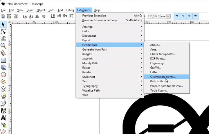
So, once we have our drawing ready, we can use the Gcodetools extension to generate the G-code. First, we need to generate Orientation points.
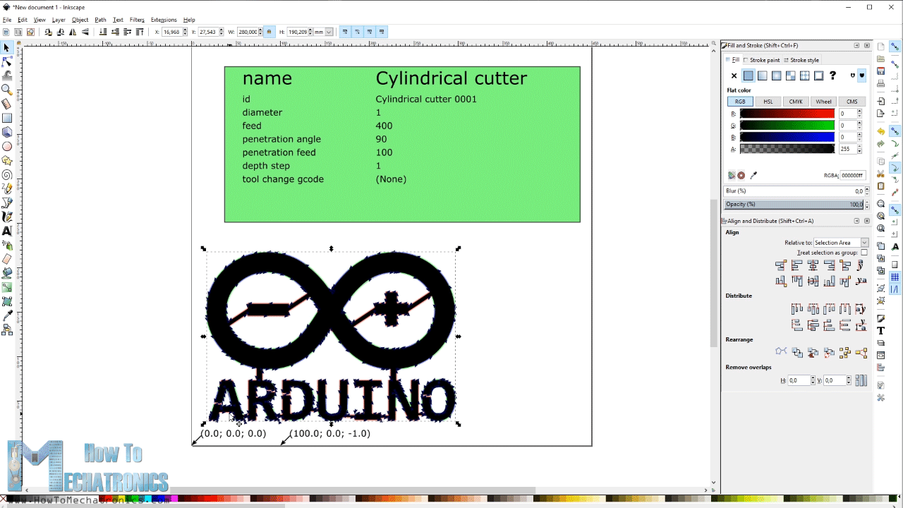
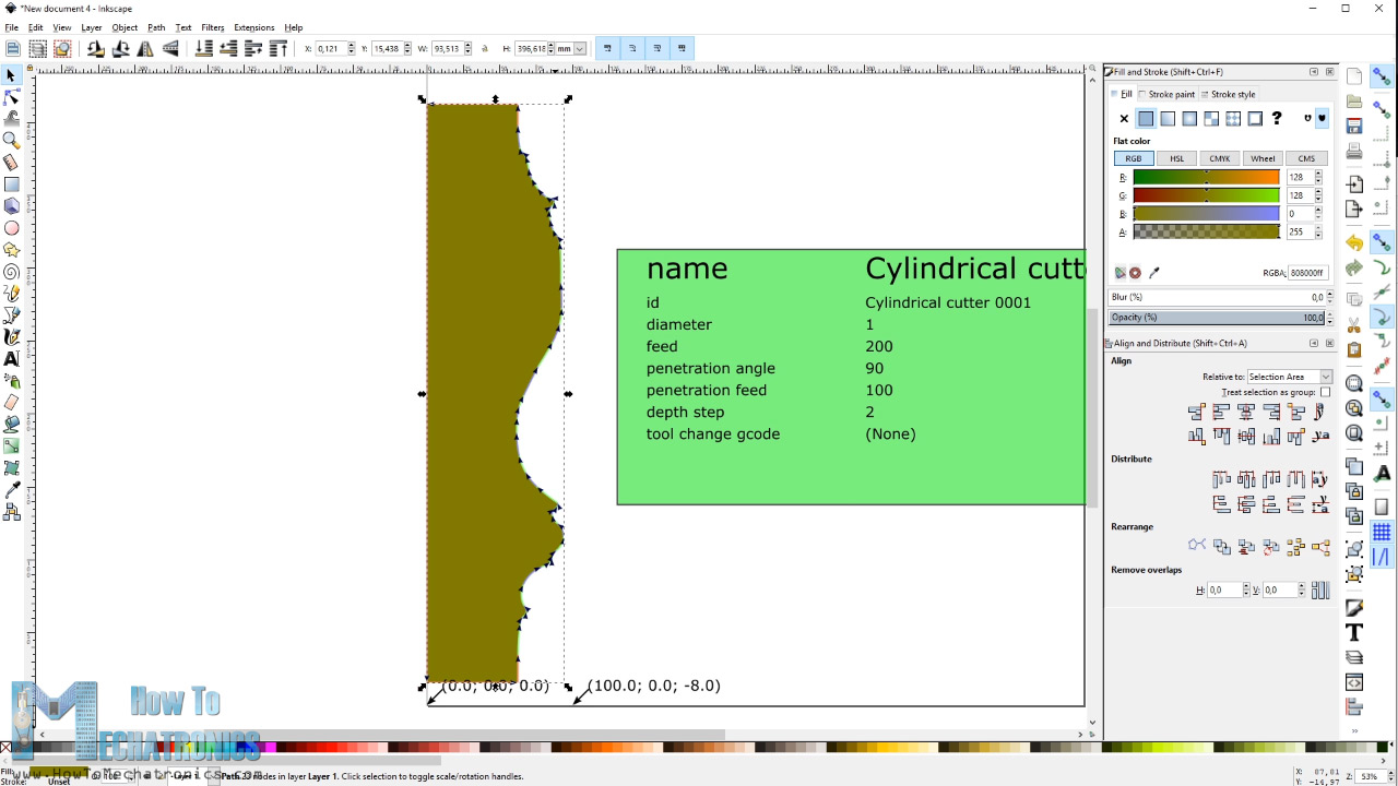
Then we can scale our model to the desired size. Next, we need to go to the tools library and with this define the tool that we are using for the Arduino CNC machine. We can select a cylinder as the wire obviously have a cylindrical shape. Here we can change the parameters like diameter of the tool, I set it to 1mm, as well as the feed rate. The other parameters are not important at this time. Finally, now we can generate the G-code for this shape using the Path to Gcode function.
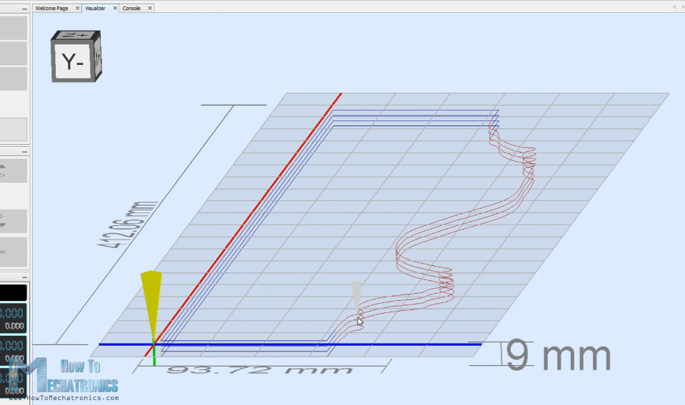
The G-code is simply a set of instructions that the GRBL or the Arduino can understand and according to them drive the stepper motors. So now, we can open the Gcode in the Univeral G-code sender program and through the Visualizer window we can see that path that the machine should go through.

However, we can notice here yellow lines which are represent an empty travel, or travel through air in case of using a bit or laser. As I mentioned earlier, in this case the hot wire cannot move on these travels, because the wire would cut through the material and ruin the shape. Here we can actually notice that we don’t have a single path for the entire shape because we forgot to open closed areas inside the logo. So, we can simply go back to the drawing, make these closed areas open and then generate the G-code again.
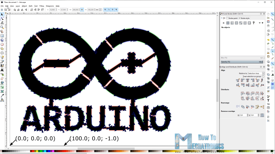
One more thing to mention that it’s good idea to select your own starting point by double clicking the shape, select a Node and select Break path at selected node. Now if we open the new G-code we can see that the path starts from the later A, goes through the whole shape, and ends back at the A letter.
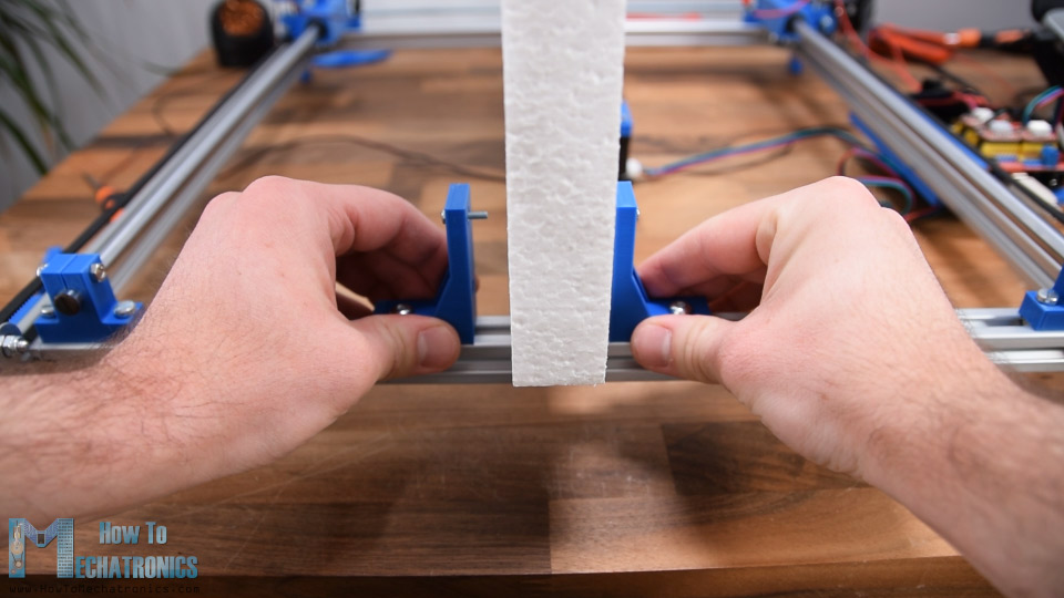
For securing the foam pieces to the CNC machine I made these simple holders which have M3 bolts that penetrate the foam and hold it in place.
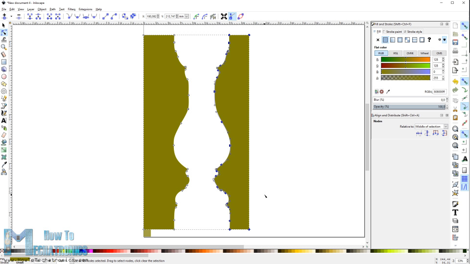
Ok, so now I will show you one more example of how to make a three-dimensional shape. We will make a square pillar shape which needs to be cut on four sides 90 degrees from each other.
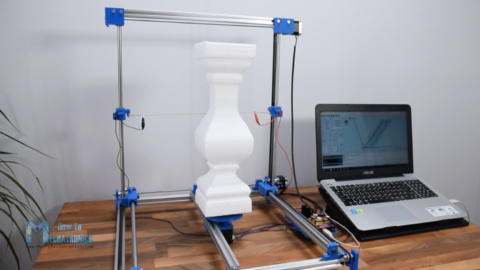
I got the pillar shape with the Trace Bitmap method shown earlier. Now we can draw a simple rectangle as big as the pillar and we will subtract the pillar from the rectangle. We will delete one of the sides as we need only one profile path of the pillar. So, this is the actual path that CNC machine should make, and after each passing, we need to rotate the 3rd stepper 90 degrees.
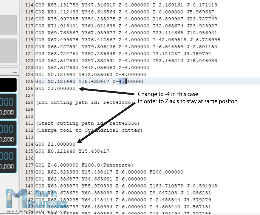
In order to do that when creating the Orientation points, we need to set the Z depth to -8mm. Then in the tool parameters we need to set the depth step to value of 2mm. Now after generating the G-code, we can open it in the G-code sender and we can see that the machine will do 4 passes of the same path at 2mm depth difference. In case of a CNC router that would mean that each time the bit will get 2mm deeper to cut the material, but here as show earlier, we set the Z axis to rotate 45 degrees with each millimeter or 90 degrees for 2mm Z stepper motor travel.
Anyway, here we also need to modify the G-code a little bit. By default, the generated G-code after each passing moves the Z axis to value of 1mm, which in case of CNC router it means that it raises the bit when an empty travel is needed.
Actually, we could leave G-code unmodified but it will make unnecessary movements of the Z axis, or rotate the foam for no reason. Therefore, after each iteration of the code we just have to modify the Z axis values to stay at the same place, without moving back to the value of 1mm.
For mounting the foam piece for making the 3D shape, we use this platform which contains some M3 bolts that get stacked into the foam piece and they hold it while it’s being shaped.
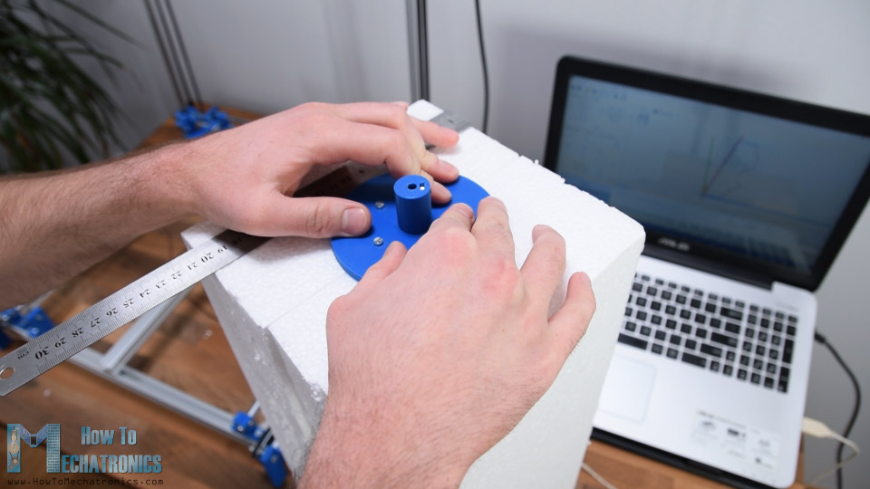
Before running the G-code, we need to manually bring the hot wire near the foam piece. The distance from the center to the hot wire should be as much as we want our shape to be tick. Or in case we want the exact dimension like in the drawing we need to measure distance from the origin to the center of the shape in the drawing.
Then we need to click the Reset Zero button in the controller in order to tell the program that it should start from here, instead of the home position. And that’s it, now we just have to click Play button and the Arduino CNC machine will make the 3D shape.
You can download the G-code files and the Inkscape files for all example here:
So that’s pretty much everything for this tutorial. I hope the explanation was clear enough and that you will be able to make your own CNC machine. Feel free to ask any question in the comments section below and check my Arduino Projects Collection.
Hi;
I’m from Türkiye, my name is Hasan.
I started make this cnc hor wire machine. I have some quastion;
I have Arduino Mega anad Raprap card. is that possible use this cards for this project or not?
Thanks for your help.
Hi, sure you can use that combination of hardware and software, it is just a bit different the programming and the control.
Thank you for your detailed explanation. We made the prototype. We have a problem. The machine is only working with the Normally Open Limit Switches, not with the Normally Closed Limit Switches. When I use Normally Open Limit Switches, it immediately stops with alarm: Homing fails. When I use the Normally Closed Limit Switches, it works for Homing but when I try to cut any shape, it stops with the error: Hard limit triggered (I think the noise from the limit switch as you mentioned in your video). I am not able to understand why it does not work with NO Limit Switches. I understand for NC Limit Switches. I think the noise comes in both situations. Am I right? What could be the solution to this problem? How can I filter noise? Where can I connect resistor and capacitor?
Well yeah, that can be a problem sometimes due to noise. Check out this article from github which might be useful for solving the issue: https://github.com/gnea/grbl/wiki/Wiring-Limit-Switches
Hello. Replayed your project. He is beautiful! I am from Ukraine and I do not speak English well. I have a problem that recurs when sending G-code to the machine Universal Gcode sender keeps giving this error “An error was detected while sending ‘G00Z5’: (ALARM: 2) Soft limit alarm. G-code motion target exceeds machine travel. Machine position retained. Alarm may be safely unlocked. Streaming has been paused. ” I ask for help on how to solve this problem. Thank.
Hey, the problem seems to be with the limit switches. Either they are not connected properly or the is a electrical noise causing them to fail. You can use some resistors and capacitors for noise filtering.
Today, by the end of the day, we managed to randomly partially solve the problem or find a clue. I reset the coordinates, send g code for cutting, the result is nothing, the result is as I described above. But, if you rotate the Z axis, for example, lower it to – 14,000 and then reset the coordinates, then when you restart the cut, g code starts working. This should not be so, but at least some progress. What did I do wrong with the Z axis? P.S. I also noticed such a thing that if you touch the driver’s radiator with your finger, the machine may freeze. Is this a tip?
what type of paint and hardner do you use to fish your parts?
I didn’t use any paint or hardener for the part in this project.
I drive thousands of kilometres each month in VietNam on a Kymco Motorscooter. As I have a large backside I and travel up to 800 kilometres at a go, I made my ơn custom seat pads.
I constructed the Dejan 3D Foam Cutter. Since VietNam is an emerging country, not only are we flooded we Chinese products of dubious quality but we also have. at retail, wide choices of ‘raw’ materials.
Working with a custom seat manufacturer, I have managed to custom fit the underlying foam using a CNC Ultrasonic knife (from AliExpress) I made the most comfortable seat ever.
I use the Dejan 3D Foam Cutter to also cutter to process very soft cushion foam. This doesn’t involve much more than positioning the X & Y axis then lowering the hot wire Z-axis ever so slowly.
After experimentation, it is possible to cut the softest foam. Cheese next?
A very detailed explanation, and understandable dialogue you’ve given freely. Thank you from the heart. I’m about to start new chapter In my life from working in manufacturing medical parts machine shop CNC some 35 yrs ago.
This is the engineering behind it. I‘m quite stoked to CNC mill and I’m grateful for folks like yourself.
What can be the maximum dimensions that we can use for this design??
The work area for this particular configuration is around 42x32cm.
What material did you use to print the parts?
I used a normal PLA material.
Thank you so much for posting this tutorial very instructive, clear and understandable. I want to enlarge the printer for cutting larger foam wings, 1/4″ scale (probably no wider than 36″ x 12-14″ deep) how far can I safely go with having to upgrade to bigger aluminum and spend “too” much money?
Well, I don’t think it’s a good idea enlarging this design. I mean, the concept is ok, but the design itself, the 3D parts and the way everything is connected is not really good for making it bigger.
In my part of the US metric screws/nuts are difficult and expensive to source. Just an FYI to anyone with similar issues that I’ve found 8/32 nuts slide perfectly and rigidly into the aluminum profiles. You can then source appropriately sized 8/32 screws to do all of your fastening. Much much cheaper and easier to find!
This is definately my next project…excellent and inspiring …
Hello – Awesome tutorial. I just pulled the trigger and ordered almost everything needed from Amazon. Wherever possible I clicked on your links so hopefully you’ll get something!
Just two questions:
1) Total price for components was roughly $300. Does this sound about right to you?
2) I am having trouble understanding why you are using a threaded rod… Wouldn’t a straight rod also be OK? Thanks!
Hey, thanks and I’m glad you found it interesting!
1) Yeah, the price could go probably end up to $300. It depends where you order the components from, so $200 to $300.
2) I used threaded rods just because I had them laying around my workshop. Sure you can use straight rods or anything similar to transfer the motion.
As others have said, your video and instructions are incredibly well done. It is rare to see videos of this quality, conciseness, and completeness. And then you go even further by providing all the files, and links to supplies. Though, I wonder if it is possible to place a “set” of components in a list at the source, so it can be a one-click order.
My question is in regards to the circular profile you have in the foreground of the 1st image on this page. I am guessing that it is done in a similar way to the 3d Profile of the Square Column. But, perhaps by increasing the number of turns substantially. Is that correct?
Thank you, I’m glad you find my work interesting!
I don’t think I can place a “set” of components in a list so it would be one-click order. Some items often run out of stock, it’s not something that I have a control over, all of them are external links.
As for the “Bishop” chess shape, yeah, you’ve guessed right, It’s the same method as the Square column example, just increased number of turns. I think I did 18 turns for that example.
Hi Dejan exceptional work, explained in detail, really very professional, I just wanted to ask you for an info before, start with the creation, I don’t care about the z axis, and I need other mounting measures, but on the programming part arduino, if I do everything as described and do not mount the Z motor, does everything work for me? mounting only X and Y? I don’t know if I am displaced, I only have to cut some panels and not polysitrol cubes, thanks
Hey, thanks! Sure, you don’t have to use the Z motor. You just have to follow the steps as explained in the video, and it would work even without the Z motor.
I bought 6 piecea of 500mm sigma profiles but the profile on the top is short. What do i need to do?
Well maybe you could use the leftover piece from the shorter profile (440mm), and extend it with that profile. You could make a connector out of simple flat profile and just bolt it using the T-slot nuts.
Wow this is amazing! Thank you so much for being so clear about assembly and just as importantly about the bill of materials/where to get all the parts!
One question – What design software did you use to generate the STEP files? Is there a basic/freeware version that you would recommend for a newbie?
Thank you! I made the model using Solidworks, but as for a free CAD software I would recommend Autodesk Fusion 360. You can register as Student or Hobbyist/Maker and get a free licence.
Hello! How long are the linear rail rods?
Hey, the linear rail rods are 50cm long.
HI Dejan
Great tutorial and great product. I have made one and have it all working, i can move the x and y axis and have the x and y limit switches set NC as you said and they work fine, but the z axis says it is tripped and i cant get it to run any program as the z axis limit is tripped, I have changed the grbl config.h to be 2 axis homing first x then y but when i run the UGS setup wizard it says the z axis is tripped.
I tried to trick it by placing a jumper on the z+ limit switch connection but it did not work. I am at a stand still at present and cant get it to work. I dont think i missed a step in the limit switch setup.
Thanks in advance
Russell allen
Hey, thanks! I didn’t have any problem with the Z axis. Just make sure you change the grbl config.h file as explained, and also make sure you reupload the grblUpload example again to the Arduino, as the changes in the config.h to to be uploaded to the Arduino.
Awesome, Great explanation and thanks for all the links to purchase require parts. That was my main concern with other videos on youtubes, I didnt know what they used but this blog answers all my questions. Will definately going to build this machine.
Thanks, I’m glad you found it useful!
Building now. Another issue came up. The threaded rod for the x-axis needs to be about 56 cm long. 50 is too short.
This is wrong sorry. I hadn’t realized that two of the profiles need to be shortened, making the 50cm threaded work.
I ran into a similar issue watching the video vs checking the CAD file so just modified the shaft coupler to create an extension. I cut the coupler in half and add a 5mm nipple on the other side to bridge the gap. Didn’t want to disassemble cut & reassemble 😉 and haven’t had any performance issues.
I built this with my kids (13, 11 & 9)… As a next step, we’ll be using the foam positives to cast our creations in aluminum.
Very good tutorial, I have already designed my 2 and 4 axis foam cutters. I use free and also expensive software to run my CNCs. I was trying to implement a third axis, and your information was very helpful. My main interest is to use my machines to build my rc planes.
Hi great project.
In your mechanical parts list you don’t specify the bearing size for the threaded rod end opposite the stepper. In the video you mention 6mm id but the pulleys you linked in the parts list are 5mm. So I’ll need a 5mm bearing to match the 5mm rod.
Hey, thanks! Well yeah, in the video I used 6mm bearings, pulleys and threaded rod but I would suggest to use 5mm ones because these are more common dimensions for those parts and it’s easier to get them. You see they even come as a bundle containing belt, pulleys and idler pulleys, because they are commonly used in DIY 3D printers. Therefore, I also included two versions of the shaft couplers and the mounting brackets to mach these dimensions. So make sure you consider this when 3D printing those parts. I also updated the article with this note.
Anyway, thanks for the input so I hope now I cleared the things a little bit about this.
Thanks for the quick reply.
Another minor issue but maybe this one is due to a change or maybe my arduino is made by others but the hole pattern on my (1 month old) UNO R3 doesn’t match up with your arduino controller case’s hole pattern. I just drilled a new hole for it in my print to make mine work, easy fix. But I thought others might benefit if they check the hole pattern against their UNO before printing.
Great Job!! Creating the foam cutter and even higher praise for a thorough and complete explanation. Look forward to more of your projects
This is a great project congratulations for this achievement!!
I am wondering what gauge of hot wire do you use in your prototype?
Thank you! The hot wire I used had a diameter of 0.6mm.
Inspired by you, I made many structural improvements, which made it very stable and durable!
Great tutorial. Is there a easy to make non symmetric 3D parts? For example an aircraft fuselage? I build RC airplanes. One method I use requires slicing a 3d model to get the profile every few inches. Then make a wire guide template and hand cut with a hot wire all the segments. This is very time consuming.
Thanks! Well with this configuration of the machine we couldn’t make non symmetric parts. For that purpose we would need the two Y axis towers or sliding blocks to have 2 separate motors and work independently, while here they are doing the same movements. Sure it’s possible and there are some DIY machines on the net with that feature. Maybe I would make such modifications when day when I decide to play around with RC planes, but to be honest I don’t know when it would be.
it’s wonderful project
I wait for a long time with your project! But now ,it’s wonderful.