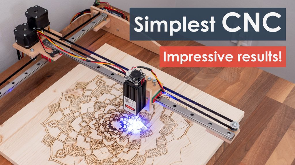
In this tutorial I will show you how I built a CNC pen plotter or a drawing machine but with one cool feature and that’s automatic tool change. In other words, the machine will be able to automatically change colors and so we can draw really cool stuff with it.
You can watch the following video or read the written tutorial below.
Overview
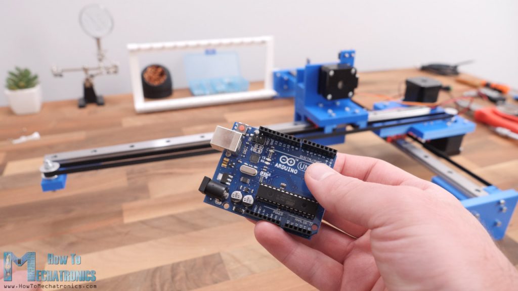
The construction of the machine is based on my DIY CNC Laser Engraver machine from my previous video where the goal was to make the simplest CNC machine with minimum parts possible. It uses 3 NEMA 17 stepper motors for the X, Y and the Z axis motion, and a small servo for the gripper. The brain of this CNC Pen plotter machine is an Arduino UNO board in combination with a CNC shield and three A4988 stepper drivers.
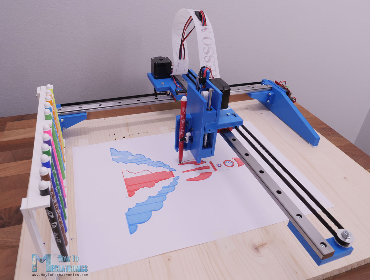
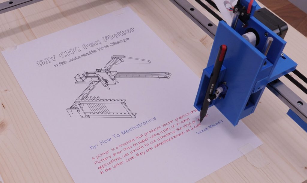
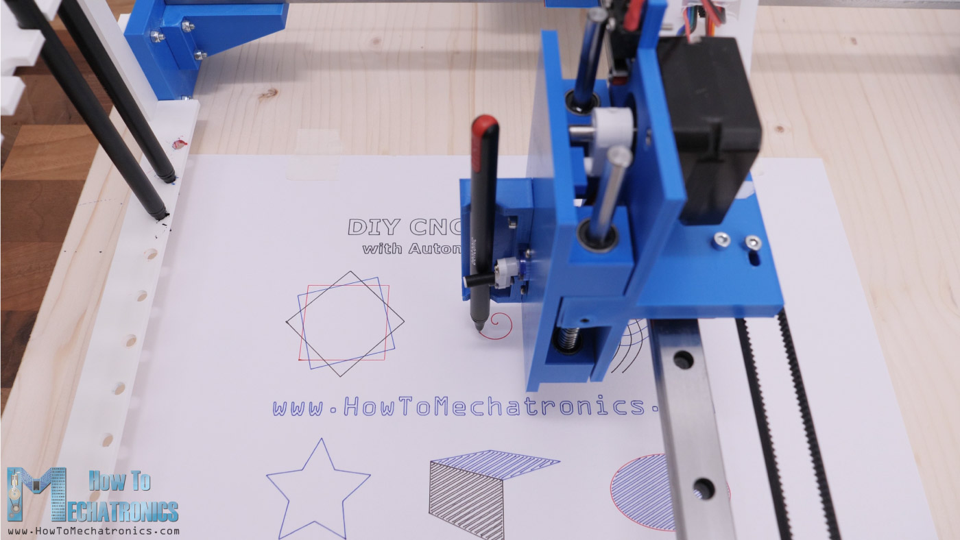
The work area of fairly big, 360x280mm, and the level of details this pen plotter can output is in my opinion quite impressive too. I was actually surprised how good and precise the drawings came out, especially the ones where I used a 0.6mm gel pen.
Nevertheless, now I will explain everything you need to know about building a drawing machine like this, including how to design it, connect the electronics, what firmware and software to use and how to generate G-code for it.
DIY CNC Pen Plotter 3D Model
To begin with, let’s have a look at the design of this CNC machine. As I already mentioned, this machine is based on the design of my previous CNC laser engraver machine where the goal was to make a very simple CNC with minimum parts possible.
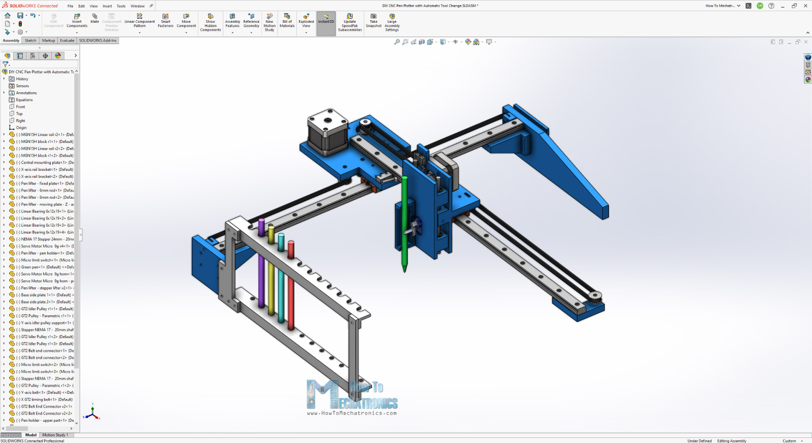
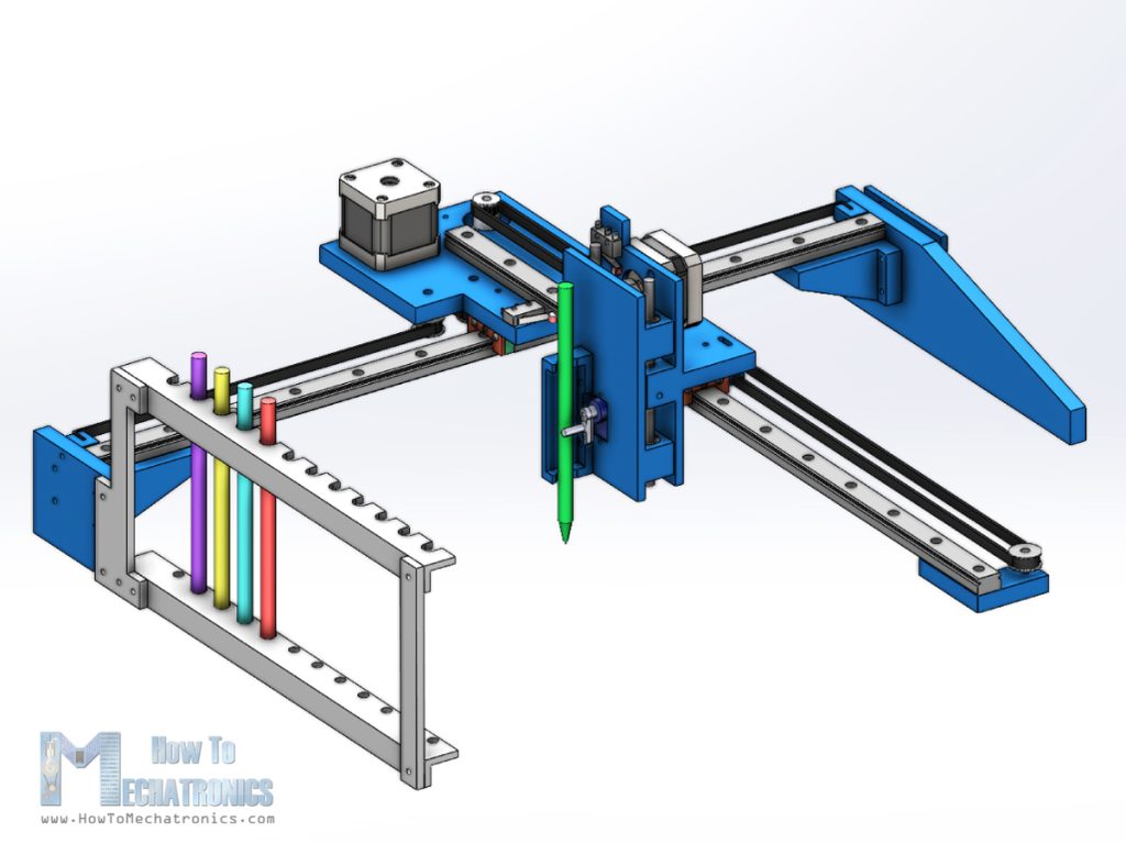
The two main components are the MGN15H linear rails, together with their suitable sliding blocks. The motion for the X and the Y axes is provided through two GT2 Belts and some GT2 pulleys. As for the Z-axis, we have a simple reciprocating motion where the moving part slides up and down on two 6mm linear rods and suitable linear bearings. A small, hobby servo is used for gripping the pen.
A homing procedure is essential for this pen plotter as the pen holders have a specific fixed position, so the machine must have a starting point. Therefore, we must have a limit switch for each axis.
3D Model and STL Download Files
You can get this 3D model, as well as the STL files for 3D Printing from Cults3D.
Assembling the machine
Here are all the parts needed for assembling the pen plotter.
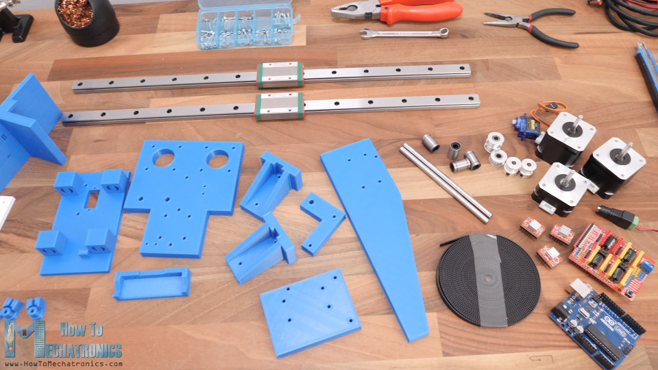
Here’s a list of components needed for assembling this DIY CNC machine. The list for the electronics components can be found below in the circuit diagram section of the article.
- MGN15H Linear Rail ………………………… Amazon / Banggood / AliExpress
- Linear Rod 6mm ……………………………….. Amazon / AliExpress
- Linear Bearing 6mm …………………………. Amazon / AliExpress
- Stepper Motor – NEMA 17 …………….… Amazon / Banggood / AliExpress
- GT2 Belt + Tooth Pulley……………….…… Amazon / Banggood / AliExpress
- GT2 Idler Pulley ………………………….….… Amazon / Banggood / AliExpress
- Spacer Nuts …………………………….……….. Amazon / Banggood / AliExpress
- Bolts and Nuts set ……………………….…… Amazon / Banggood / AliExpress or from local hardware store + Flat Head Screws 3x16mm
Disclosure: These are affiliate links. As an Amazon Associate I earn from qualifying purchases.
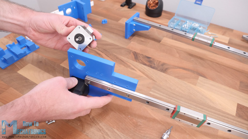
All right, so now we can start assembling the machine. I started by securing the base plate and the bracket for the linear rail together with the help of some M3 bolts. All of the bolts for assembling this machine are actually M3 with various lengths except for few M5 bolts needed for GT2 pulleys.
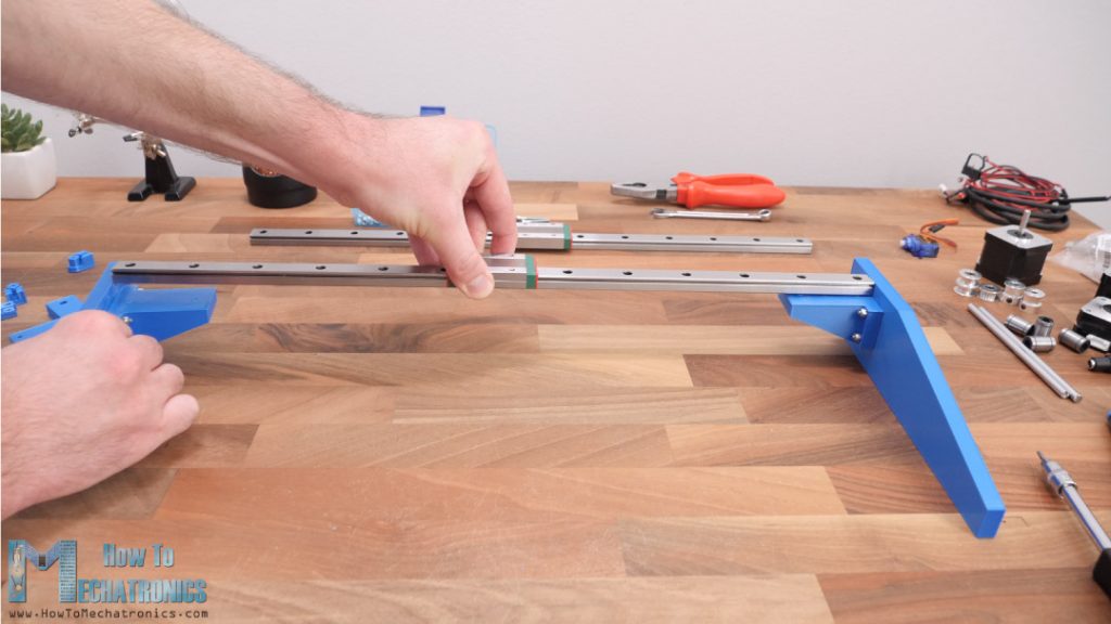
Once we have the two sides ready, we can secure the X-axis linear rail to them with two bolts on each side. These MGN15H rails provide very smooth and play free motion, as their sliding blocks have balls or rollers inside them.
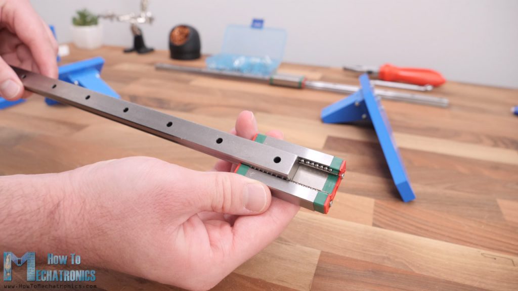
However, before installing them, it’s a good idea to clean and grease them well in order to work properly.
Next, the Y-axis rail should go on top of the X-axis sliding block and for securing them together we will use a central mounting plate. First, we can install the Y-axis rail to the central plate using three bolts.
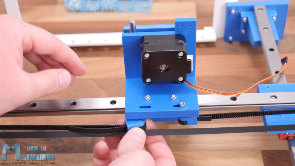
Then we can install the two NEMA 17 stepper motors. One goes on the top side and the other at the bottom side of the plate. As I mentioned earlier, we need some M5 bolts and nuts for installing the GT2 pulleys in place. The two pulleys here are actually idler pulleys which are used for providing grip for the X-axis GT2 belt and the toothed pulley which goes on the stepper motor.
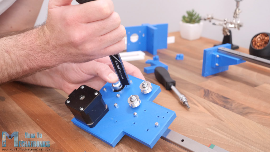
As for installing that pulley, we should measure and level it according to the idler pulleys. As for the Y-axis, we only need one idler pulley which goes on the other side of the rail, as the belt for this axis will be installed in a loop.
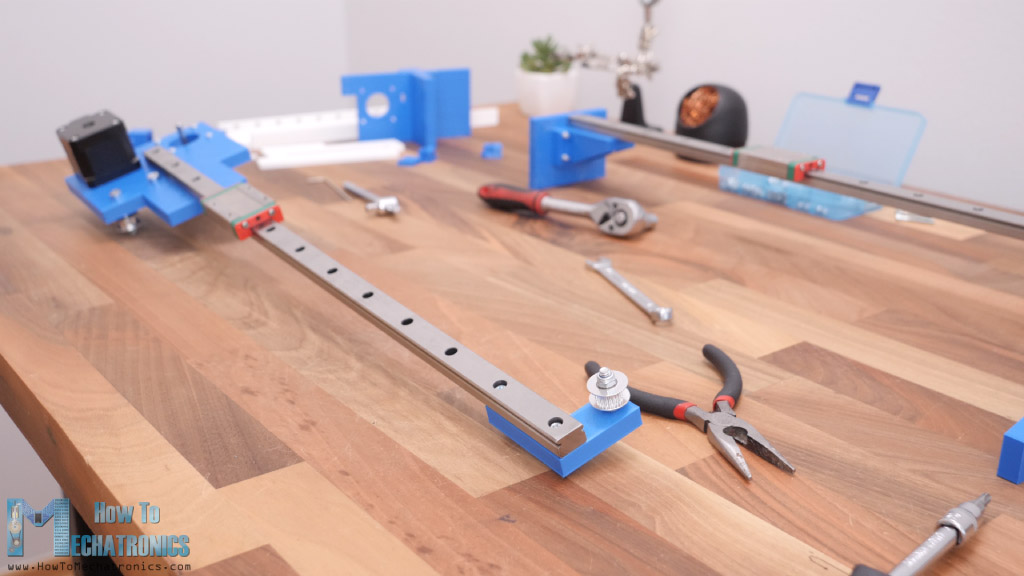
Ok, next is the marriage or connecting the two axes together. We simply do that by securing the central plate to the X-axis sliding block using four M3 bolts. With this the machine got its main shape and now the Y-axis sliding block can reach any position in the work area.
We can continue now with assembling the pen lifter mechanism. This mechanism is composed of two parts, one fixed that’s bolted to the Y-axis sliding block, and the other one that will be sliding up and down. Once the fixed part is secured in place, we can install the Z-axis stepper motor on it. This stepper is also a NEMA 17 but it’s shorter, 23mm instead of 40mm, in order to cut on weight.
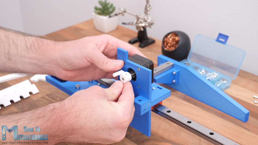
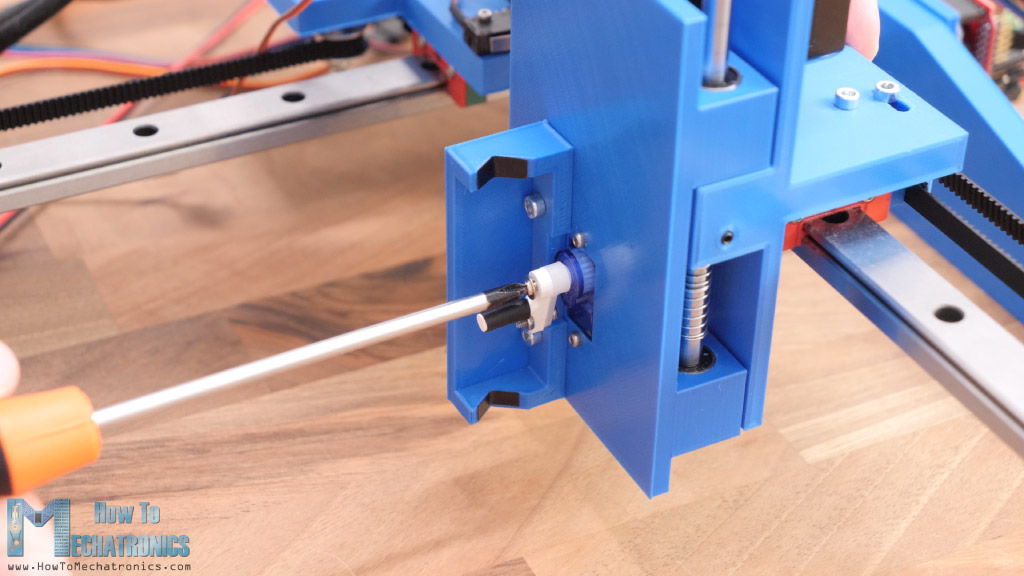
Then we can install the lifter which is simply attached to the shaft of the stepper. The grub screw that I had was a bit long for it, so I put lifter to the shaft without it, but its hole has a shape as the shaft so the motion will be transferred well. I actually ended up modifying this part a little but, no worries you will get the updated version of it in the download files.
Next, I inserted the four linear bearings into the sliding part and secured the micro servo in place. Then I also secured the pen holder part right next to the servo.
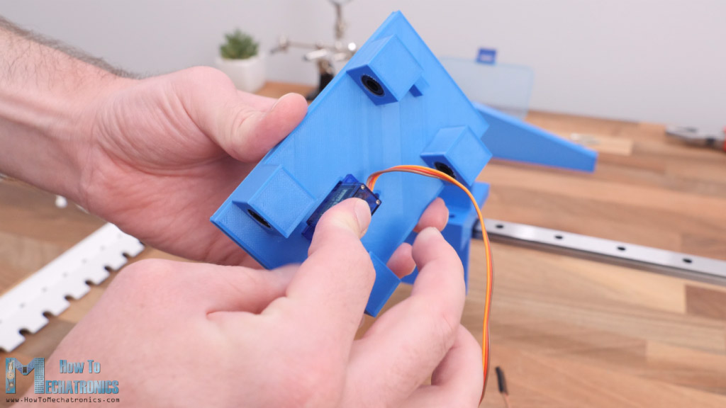
For connecting the fixed and the sliding parts together, first we need to pass the servo wire through a hole in the fixed part and then insert the 6mm rods from the top, through the bearings and the fixed part hole. While installing this rod, we should also insert a spring in-between the fixed and the sliding part in a way that it pushes the sliding part down.
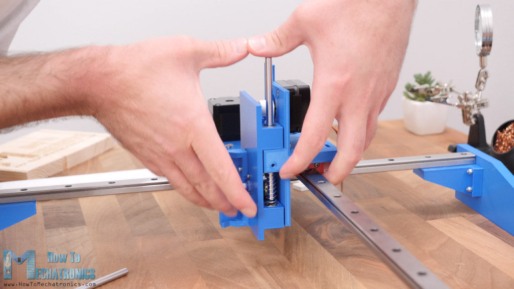
This will help the pen to have a better contact with the work surface. At the bottom side of the fixed part, there are opening where we can insert M3 nuts and use them for securing the 6mm rods in place.
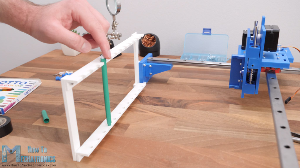
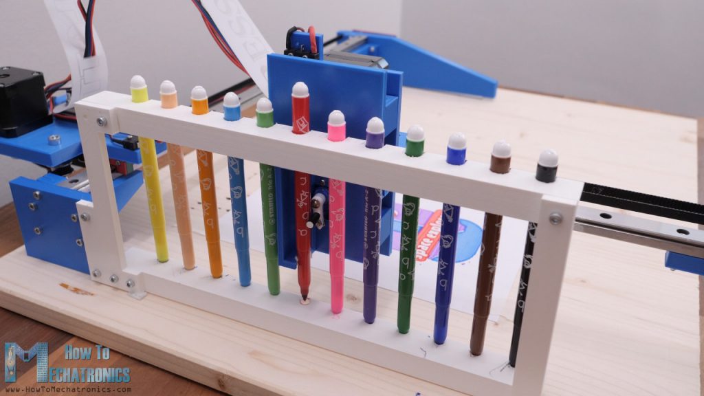
Next, we can assemble the pens holder unit that goes on one side of the machine. It’s composed of top and a bottom part with openings to accommodate up to 12 pens.
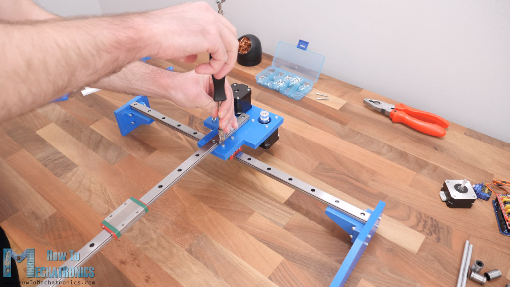
I continued with installing the belts. First, we need to measure how much length we need and cut it approximately to size. For attaching the belt to the sliding block, I made these cool belt connectors, where the belt goes around a hollow shaft and in between two walls that doesn’t allow the belt to move.
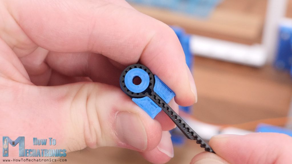
Using a M3 bolt we can secure the first connector on one side of the block, and repeat the same procedure for the other side. We can move the connectors along these slots here and so tension the belt as much as we want.
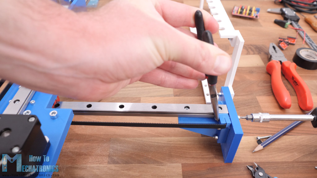
As for the X-axis, the belt will go in a straight line from one to the other side, while passing through the pulleys in a way that will provide tension or grip with the stepper motor pulley.

For tensioning the X-axis belt, I made these connectors that have a shape as the belt and so we can tight them to the sides of the machine.
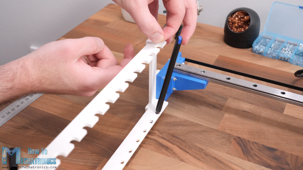
Next, we can install the limit switches.
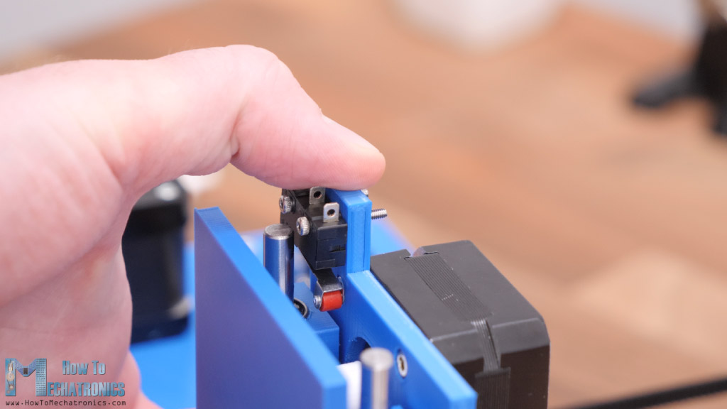
I actually ended up lowering a bit this Z-axis limit switch, and as for the X and Y limit switches I used the ones from my previous project which already had wires connected to them.
Connecting the electronics
With this the mechanical part of the machine is ready and we can move on with connecting the electronics.
As I mentioned, we are using an Arduino Uno board in combination with a CNC shield and three A4988 stepper drivers.
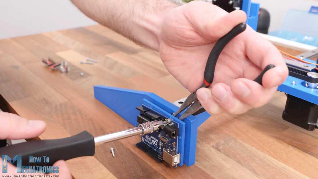
For attaching the Arduino board to machine I made an additional 3D printed part that goes on the side panel. I secured the Arduino board with two M3 bolts, and on top of it I inserted the CNC shield.
Here we need to insert three jumpers for each stepper driver in order to select 16th/step resolution, and then we insert the stepper drivers.
Then we can connect the motors to the CNC shield appropriately. For connecting the micro limit switches in place, I simple soldered wires directly to them, and on the other side soldered female pin headers which I got them from some jump wires.
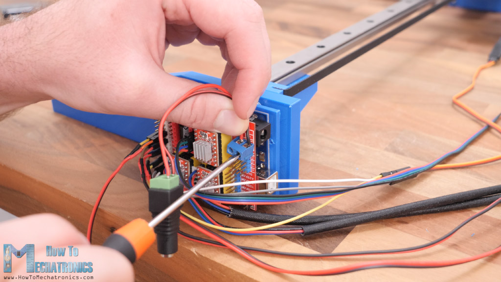
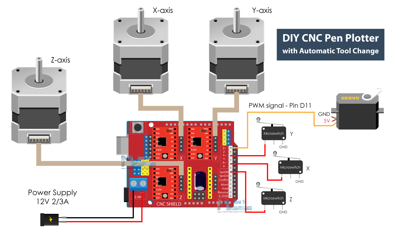
As for the servo motor, I used some servo extension cables so that it can reach the CNC shield. For powering the machine, we need 12V power supply. Here’s a circuit diagram of how everything needs to be connected.
DIY CNC Pen Plotter Circuit Diagram
Here’s the circuit diagram of how everything needs to be connected.
You can get the components needed for this project from the links below:
- Stepper Motor – NEMA 17……………… Amazon / Banggood / AliExpress
- Stepper Motor – NEMA 17 23mm ….. Amazon / Banggood / AliExpress
- A4988 Stepper Driver………………..…..… Amazon / Banggood / AliExpress
- Servo Motor ………………………………….… Amazon / Banggood / AliExpress
- Arduino CNC Shield ……………………….. Amazon / Banggood / AliExpress
- Arduino Uno………………………………….… Amazon / Banggood / AliExpress
- Limit Switch ……………………………………. Amazon / Banggood / AliExpress
- DC Power Supply …………………………… Amazon / Banggood / AliExpress
Disclosure: These are affiliate links. As an Amazon Associate I earn from qualifying purchases.
So, we are using an Arduino UNO board in combination with a CNC Shield and three A4988 stepper drivers. We have three micro limit switches for homing the machine and a small servo motor for the gripper mechanism. For powering we need 12v power supply with a minimum current rate of 2 amps.
Finishing the machine assembly
There few final touches that needs to be done in order to complete this pen plotter. Here I’m installing the pen gripper which is simply attached to the servo motor through the servo horn.
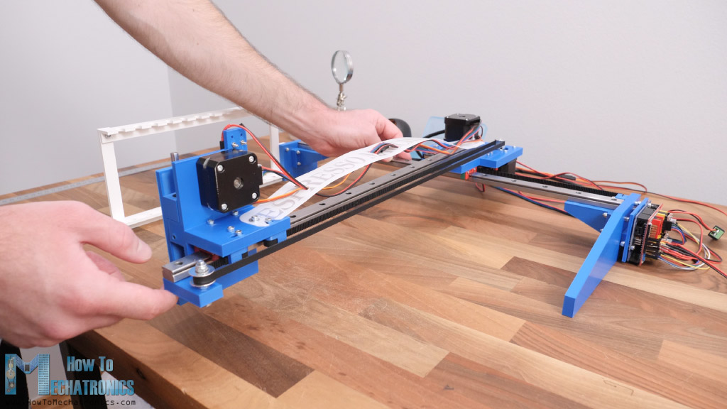
For managing the cables from the pen lifter, I used a dining table mat which material was firm but flexible, so it was perfect for the job.
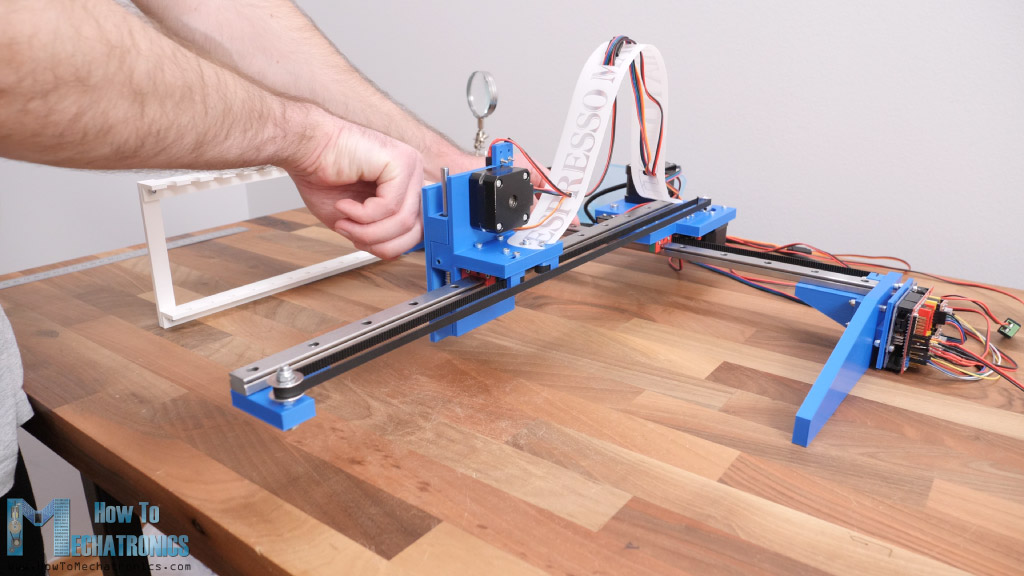
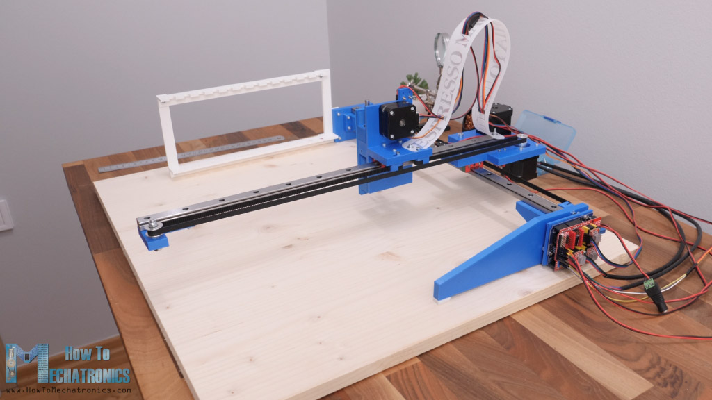
With this our drawing machine is completed. However, there are few things that we should note here. As the Y-axis rail is unsupported on one side and the 3D printing PLA material itself is not that rigid, when fully extended, the pen lifter was 4mm lower compared to the supported side.
That’s way too much play but I managed to solve that issue by lifting the front side of the machine a little bit. In this way I reduced the difference to around 1mm which was acceptable. if you plan to use these big rails, I would definitely suggest to support the Y-axis rail on the other side as well.
Another issue is the pen holder, because the pens don’t stay in place well in this way. Here I would suggest making the top openings bigger and add some soft material on the sides so that the pens stay in place while being easy for the machine to insert them.
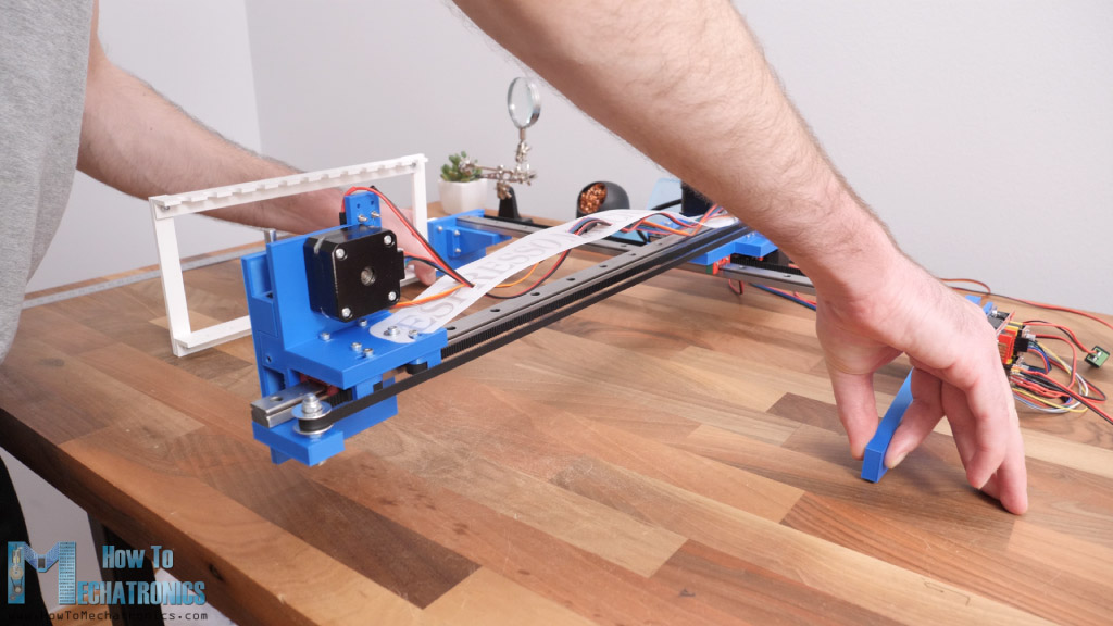
Finally, we can insert a board under the whole machine so that we get a flat surface.
And that’s it, our machine is completed.
DIY Pen Plotter Firmware and Control Software
What’s left to do now is to give life to it or make it a real CNC machine. For that purpose, we need to install a firmware to the Arduino for controlling the motion of the CNC machine and we need a control software through which we will send G-codes and tell the machine what to do.
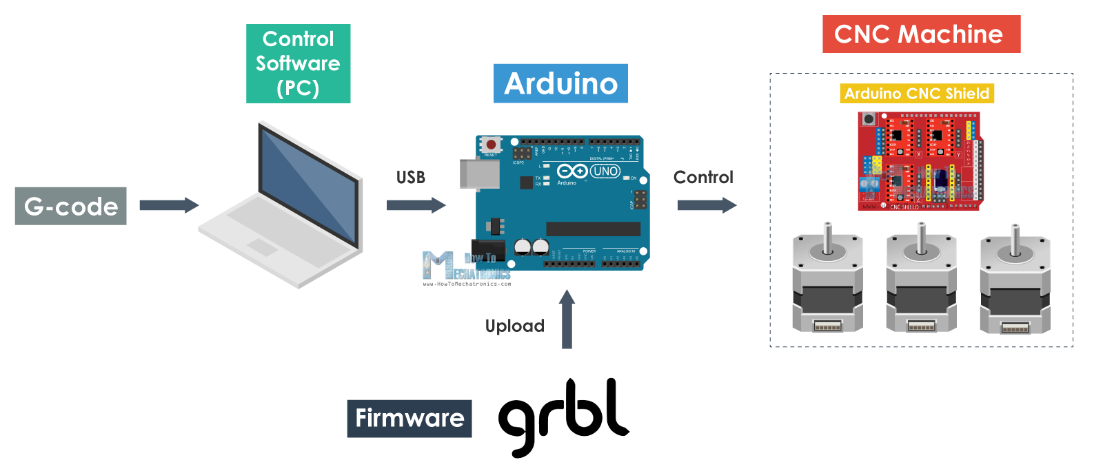
The most popular choice for DIY CNC machines is the open source GRBL firmware. However, for this pen plotter we need a modified version of it, which can control the servo motor. This modified version called “grbl-servo”, which alters the default PWM frequency of the spindle control pin (or digital pin number 11) from 1kHz to 50 Hz which is needed for controlling this type of servo motor.
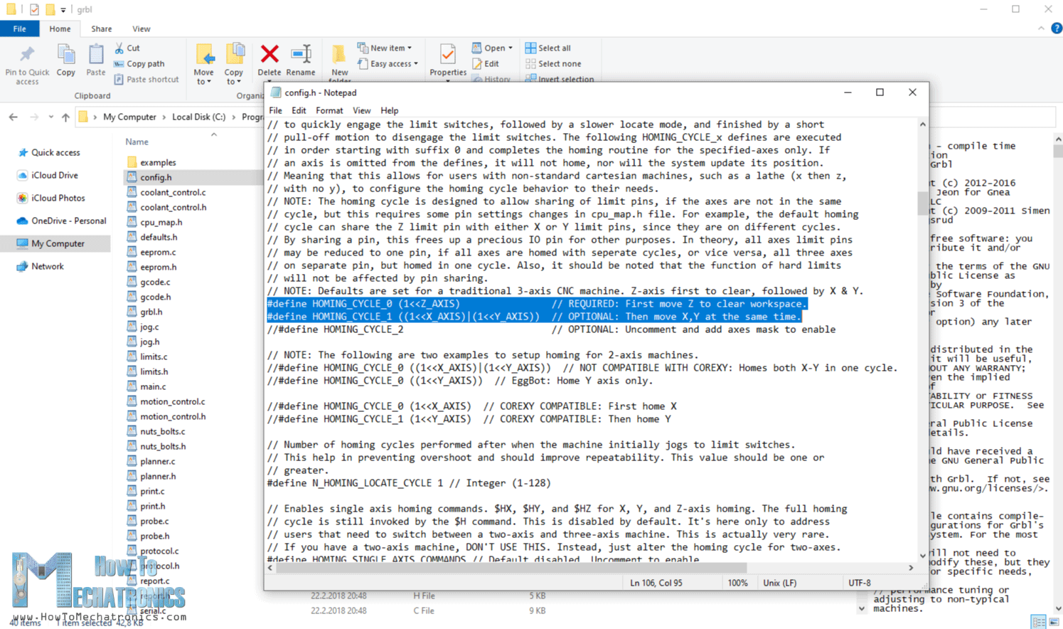
Once we download and install this GRBL firmware into the library folder of our Arduino IDE, we also need to modify its config.h file in order to enable 3 axis homing, instead of its default 2 axis homing.
As for control software, we will use GRBL-Plotter which is dedicated for controlling plotters and includes a graphics converter though which we can generate G-code from our images or graphics. This one is also open-source software which can be downloaded from Github.
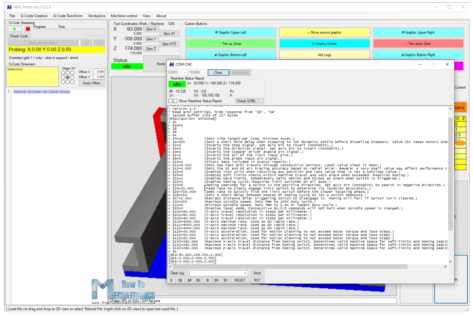
Here, the first thing we need to do is connect our Arduino board to the software through the suitable COM port. Once we click the “Kill Alarm” button, on the serial monitor we will get a list of our current GRBL parameters. We need to change some of these parameters to according to our machine.
GRBL parameters
The first thing that we should adjust here is the travel resolution or the steps/mm values. These values indicate how many steps the motor should take in order to move 1mm. This depends on the type of stepper motor that we have, the selected step resolution and motion transmission, in this case the GT2 belt and pulley.
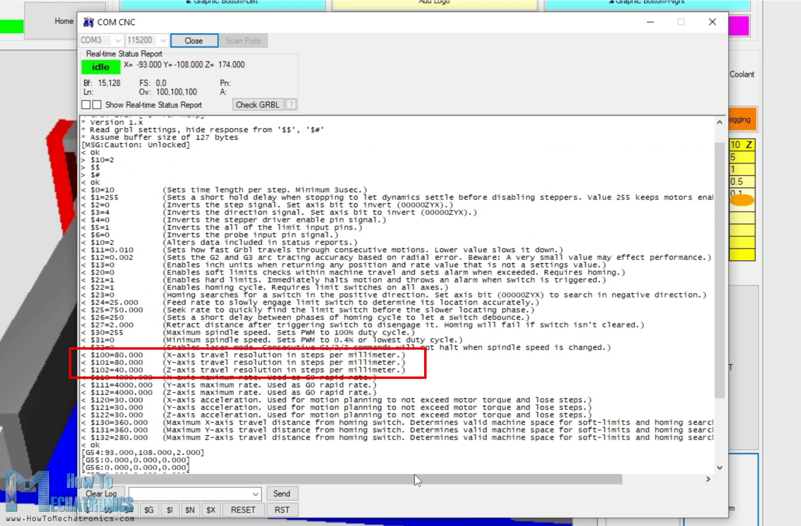
For our machine, a value of 80 steps/mm is needed for the X and Y axis to be accurate. As for the Z-axis I set a value of 40 which is actually not accurate in terms of real motion, but we cannot achieve that anyway with our reciprocating motion.
We should also set the parameter number 23, to 0, which tells where our limit switches are located, set the maximum feed rate, acceleration, maximum travel speed and the parameter number 1 to a value of 255, which keeps active the steppers all the time. However, we should note that with this enabled, especially for the Z-axis stepper, we should adjust the current limit of the A4988 driver to minimum because the shorter NEMA 17 stepper can quickly get hot.
GRBL-Plotter setup
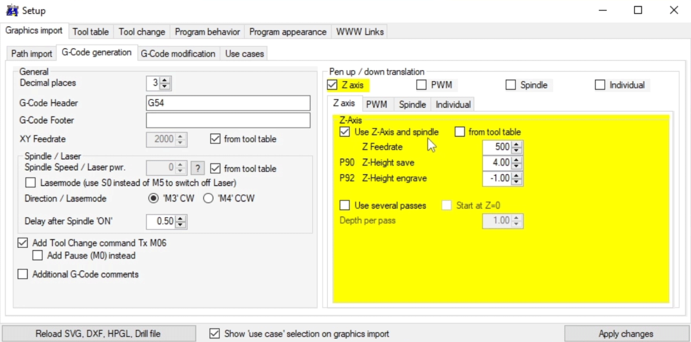
Ok, so let’s take a look at the controller setup now. There are so many options to adjust here that it can be a bit intimidating at the beginning. Here first we need to set the Pen up and down translation to be the Z-axis and set values for the Up and Down position.
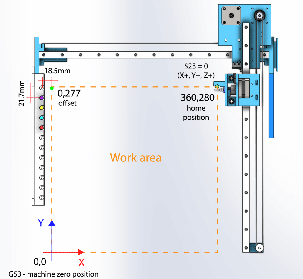
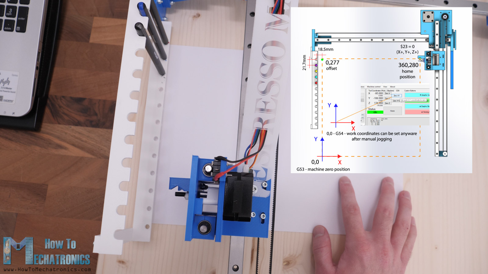
In the Tool table tab, we can define the pens color and their position. We should note here that these values are for the G53 or the machine coordinate system. This means they are defined by the hard limit switches the machine have, and the maximum travel that we set in the GRBL parameters earlier.
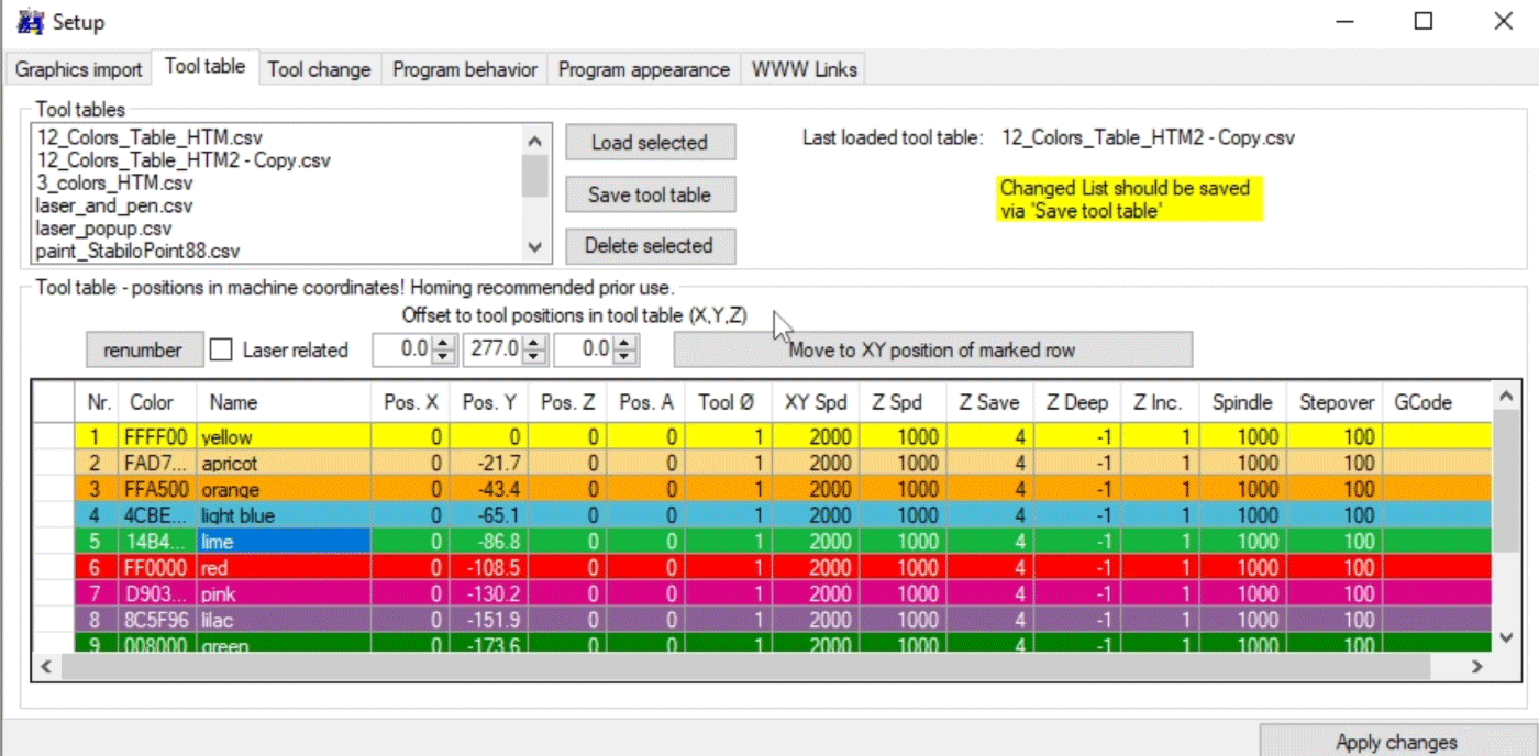
For defining the position of each pen, I used the offset values, which are 0 for the X and 277 for the Y axis in this case. These values position the gripper in front of the first pen, and then I just had to define the Y value for each pen, which is 21.7mm in the negative direction.
Here we can also adjust the feed rate and the up and down position for each pen individually, in case there are different pens.
Next in the Tool change tap we should select “Perform tool change on Tx M06” which tells the machine to do the tool change when this command appears in the G-code.
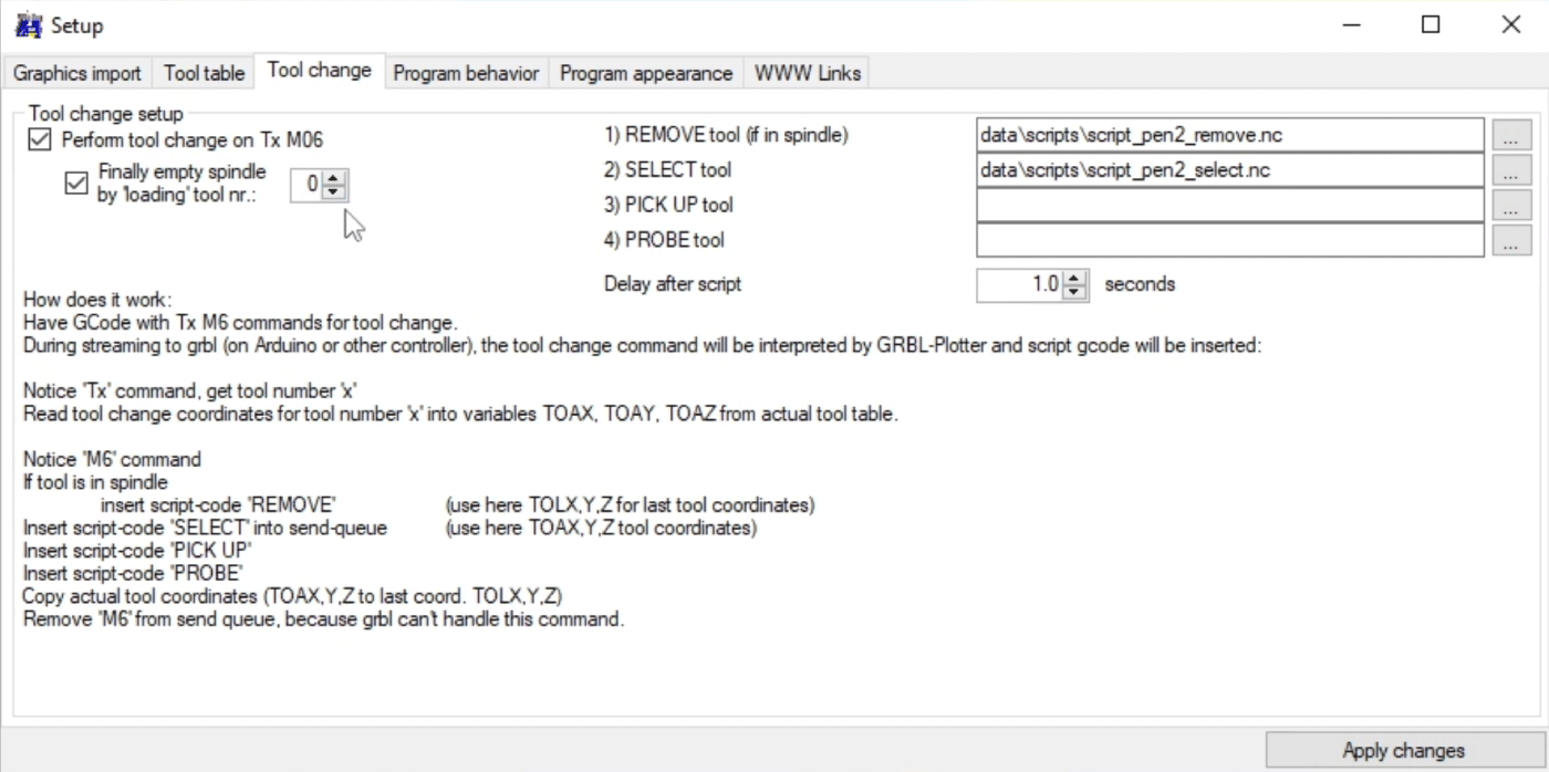
The “x” value after the letter T indicates the tool number from the tool table. To perform the tool change we must include a “select” and “remove” scripts, which are executed when the Tx M06 command appear. In these scripts we define the movement of the gripper in order to take or remove the tool.
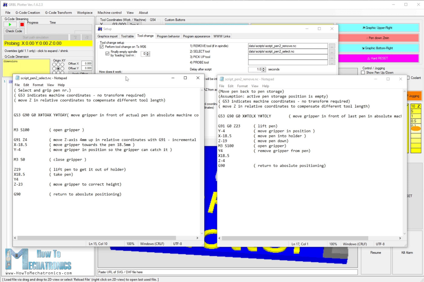
For selecting a pen, the gripper is first positioned in front of the actual pen in absolute machine coordinates, the one defined in the tool table. Then the servo opens the gripper, it moves up 4 more mm, then move towards the pen in X direction and a little bit in Y direction. Then the gripper closes, lifts the pen up and move back to the same position before executing the script. For removing the pen, the script steps are the same but in reverse order.
Of course, all of these parameters depend on the pens them self, their dimension and the dimension of the holders. The only way to get this process correct is by testing and correcting values.
Generating G-code for CNC Pen Plotter with Automatic Tool Changing
Finally, let’s take a look how we can generate G-code from images with this GRBL-Plotter software.
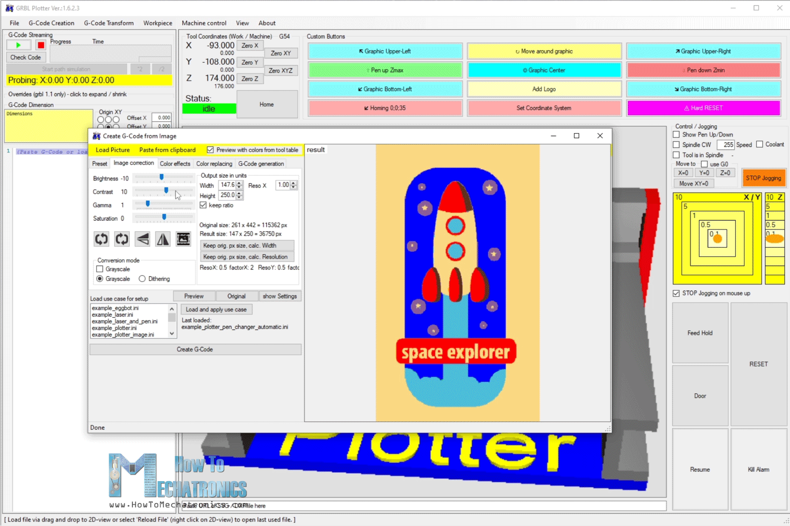
Once we load the image, we can click on “Preview with colors from table” so we can see how the image would look like. From the image correction tab then we can play with the Brightness, Contrast, Gama and Saturation values in order to achieve colors similar to the real image or that one that we actually want. We can set the output size in mm, and in the color replacing tap, we can remove the colors that we don’t want to use.
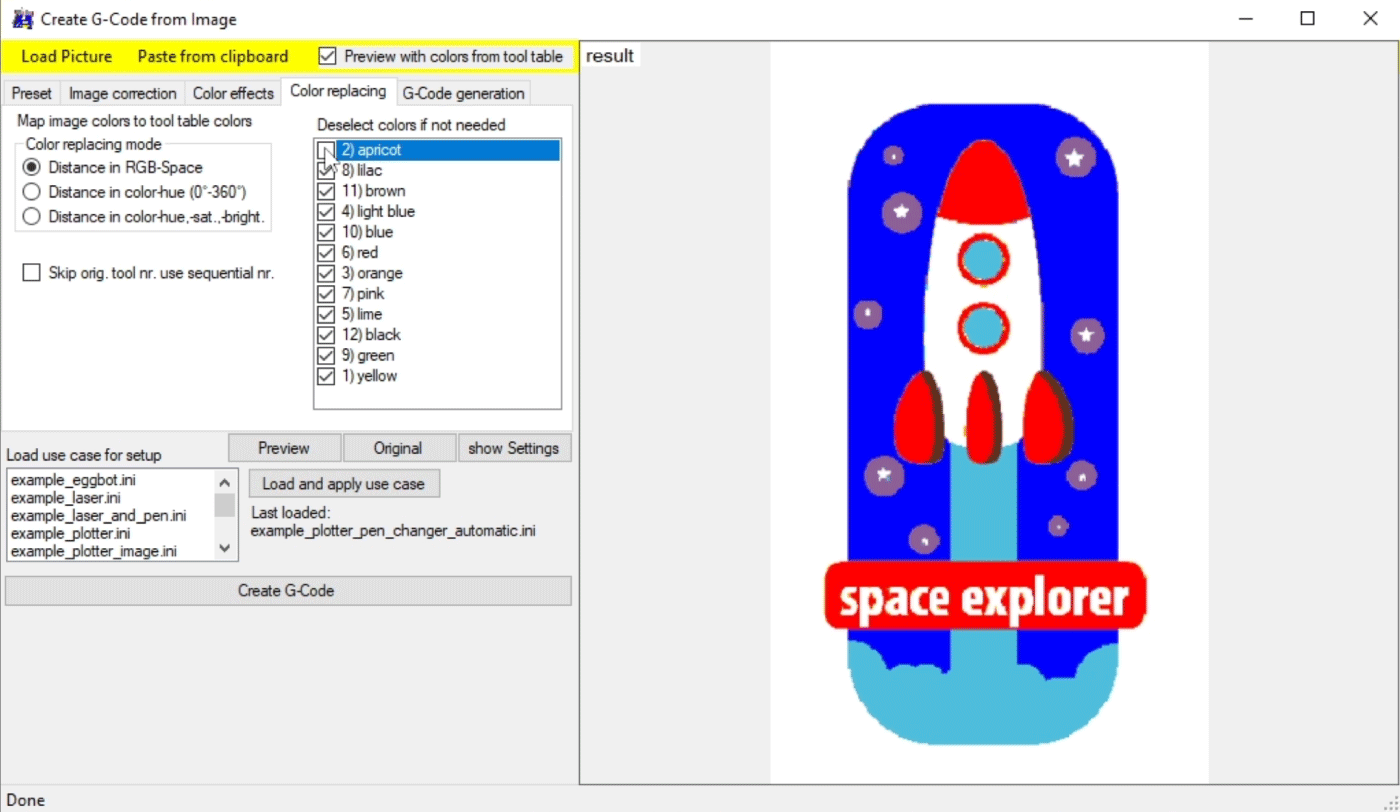
For example, we can remove the apricot color which is the white color in the image. Then we can click on Create G-Code button and the G-code will be generated.
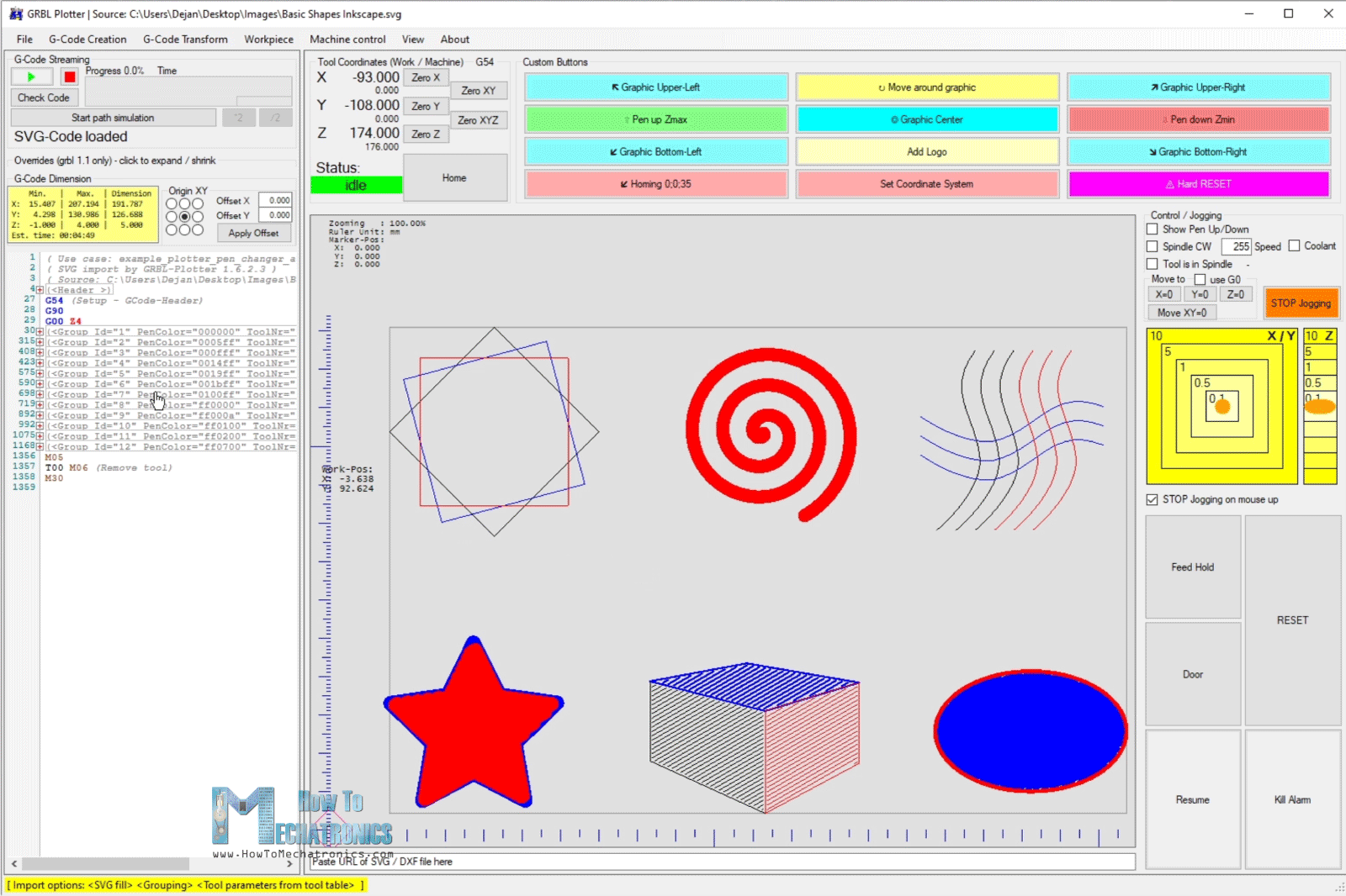
We can also generate G-codes from SVG files, which we can just drag and drop them, and the software will generate the G-code right away.
Before we start the plotting, we should set the 0 position wherever we want in the work area and then click the play button.
The pen plotter will start working and so we can enjoy watching it making magic.
I hope you enjoyed this video and learned something new. If you have any questions feel free to ask them in the comments section below.
Thank you for the amazing project Dejan,
I’ve been looking into the project and trying to put the pieces together, however, I have some difficulties finding the Stepper motors in the EU:
Stepper Motor – NEMA 17……………… Amazon / Banggood / AliExpress
Could you recommend something similar, please?
Hey, thanks! Well AliExpress is a good place to shop for shipping to EU. Check the AliExpress link now, I updated with a better option. Cheers
Thanks for an awesome first project.
Got most parts and printed parts already. Initially doing the drawing plotter and then laser engraver. Got laser already. New to arduino. Excited for next week when rails arrive. Do you think ability to add laser to other side of pen holder? Probably need another support rail if so I guess.
Thanks and have fun building one! Yeah, I would recommend adding another support rail in any case, it would be much stable.
Amazing idea. I was thinking of putting a laser on one side of the z carriages and the pen plotter on the other side of the carriage. I hope I can pull it off
Thanks! Yeah, that’s a cool idea.
I cannot download the files, This has happened on other ones too. When I try to download the stl. files it tells me to uninstall arduino in order for it redownload arduino when I am trying to download 3-D printing files. Every time I comment on the other ones it just disappears (I commented three times on the SCARA robot) PLEASE HELP.
Hey, sorry for the late response. Well, once you enter a comment it has to be manually approved in order to appear, but I simply don’t have the time to do that for each comment.
Anyways, did you manage to download the files? The should be working, try using a different web browser.
I used google and Microsoft edge and they don’t work, it tells me to uninstall Arduino in order for it redownload Arduino when I am trying to download 3-D printing files.
Can you specify the length of the MGN15H linear rail?
The rails I used are 500mm long.
Fantastic project ! ! Thank you very much for the detailed instruction that make this project doable for me.
For the printed part what setting did you use? And would printing with PET instead of PLA help with more rigidity?
Thanks! I’m a bit late with answering this but still, I used like normal settings for these budged 3D printers, 0.2mm layer height and 60mm/s speed.
PET might help with rigidity but still that won’t be enough. If you want to improve the rigidity you definitely need one more support rail on the other side.
Cheers!
Why don’t you design it as a dual X track? It’s more stable.
That can be easily added, but why bother with such result?