In this tutorial we will learn how to turn any DC motor into a stand-alone custom servo motor with a lot of features. Unlike regular servos that have limited motion of 180 or 270 degrees, this one has unlimited range of 360 degrees and in addition to that we have the ability to adjust the range of the rotation to whatever value we need.
That’s quite handy I think, and on top of that, we can even adjust the center point of the servo. So, we can adjust both the center point and the range of rotation at the same time.
You can watch the following video or read the written tutorial below.
Another feature is that we can adjust the sensitivity or how quickly the servo will respond to our input. Talking about the input, we can have three different input modes.
We can control the servo with an analog voltage input or using a potentiometer, we can control the servo with an RC transmitter as well as control the servo through a serial port by entering angle values through the serial monitor on our PC or laptop.
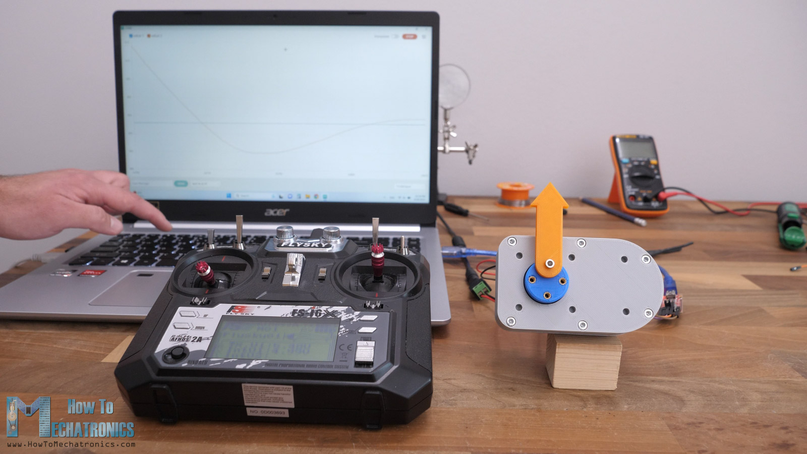
We can also do that simultaneously, control the servo by entering values through the serial monitor and manually move the servo using the RC transmitter. The servo motor will know its current position at all times and can see it on the serial monitor.
On top of this servo motor features lists, is the continuous rotation mode. That’s right. We can control and keep track of the servo motor position even in this continuous rotation mode. We can set the servo motor shaft to go to any position with an infinite number of turns.
All of this is possible thanks to the 12-bit encoder this servo motor employes, the AS5600 magnetic rotary position sensor and the implemented PID control for driving the DC motor.
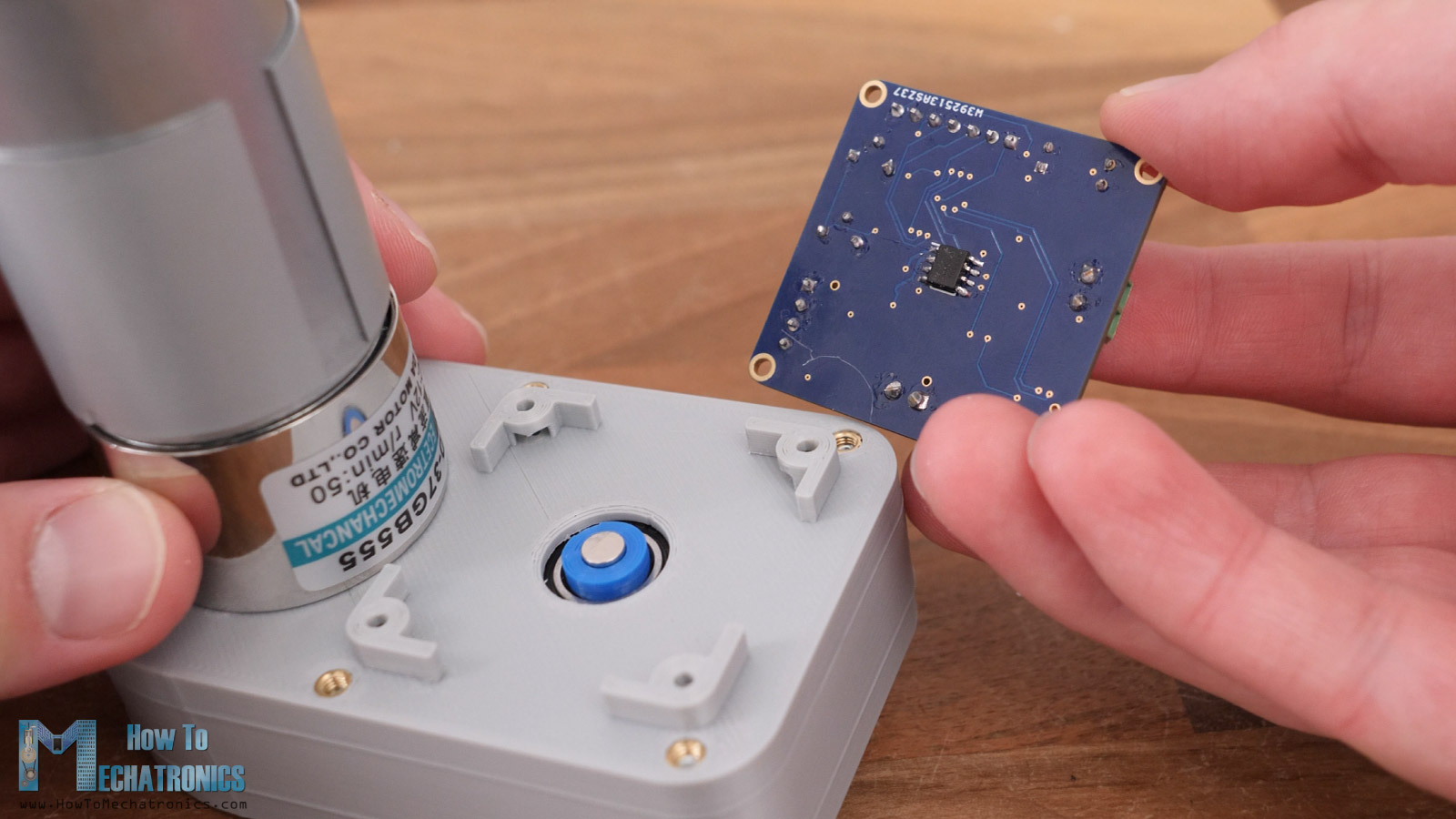
I made this custom servo motor controller board which includes its own microcontroller and everything else to easily turn any DC motor into a stand-alone servo motor.
We just have to position the board at the center of the output shaft (including a specific magnet on the shaft), connect any size of DC motor with up to 3.5A rated current, power the whole system with 12V and that’s it, we get a servo motor from a normal DC motor with all these features.
Now I will walk you through the entire process of making this custom-built servo motor so you can also make one on your own. I will explain the working principle of a servo motor, a closed-loop controller, a PID controller, how I designed the custom PCB for it and gearbox, as well as explain the code behind it.
Servo Motor Working Principle
In order to explain the working principle of a servo motor, let’s take apart a typical RC servo motor and see what’s inside.
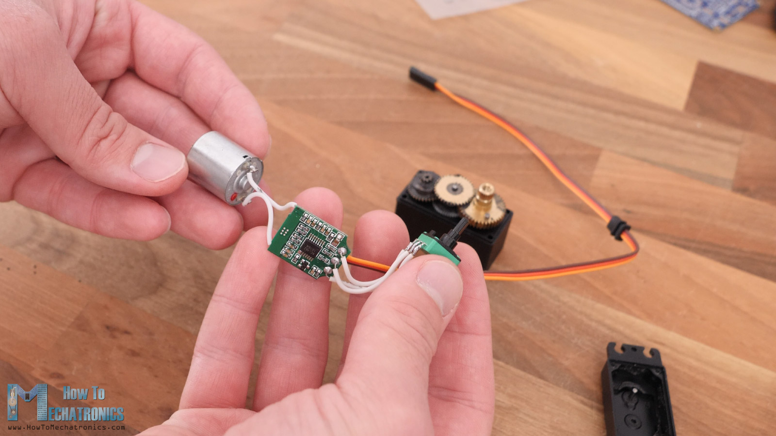
We can notice that it has a small DC motor, a controller board, a potentiometer and a three-wires connection, two wires for the power and one for the input signal. Also, there are some gears for reducing the speed and increasing the torque of the DC motor.
This is a typical setup for most RC or hobby servo motors. The potentiometer is attached to the output shaft of the DC motor, and it acts as position sensor, it tells the controller the current position of the servo motor shaft. The controller board controls the DC motor based on input signal (the desired position) and the actual position that we get as feedback from the potentiometer. This represents a closed-loop control system.
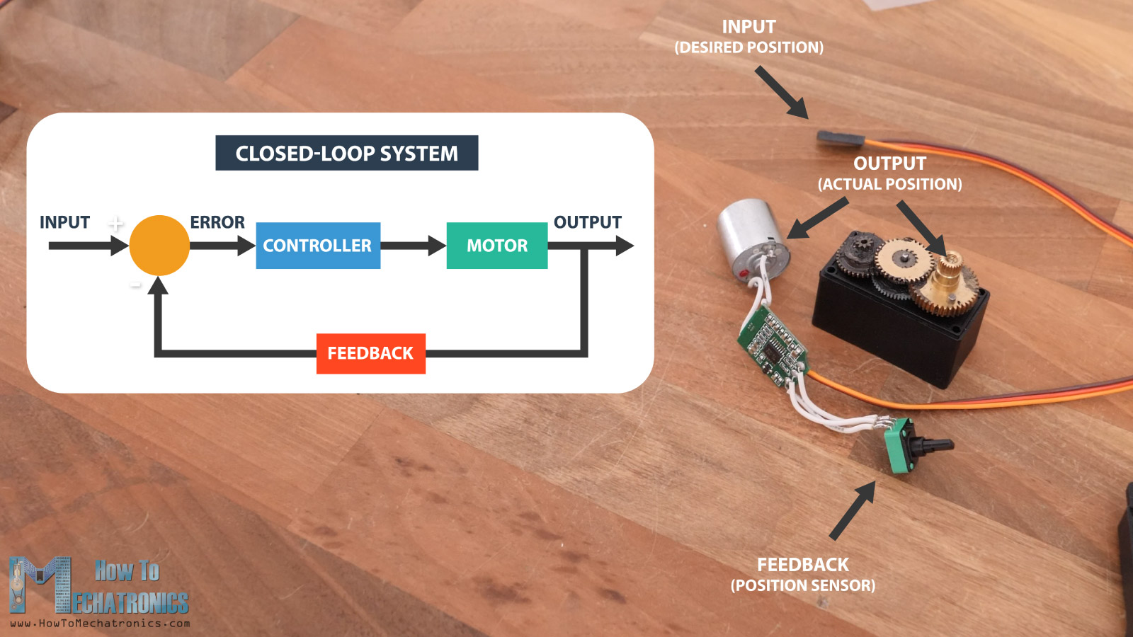
The input signal, or the desired position is compared to the actual position of the motor that we get from the position feedback sensor. The difference that occurs, which is called the error, is then processed in the controller which commands the motor to move until it reaches that desired position.
How to Make a Custom Servo Motor
So, if we want to build our own servo motor with some bigger DC motors than these typical RC servos use, we can implement the same closed-loop control system.
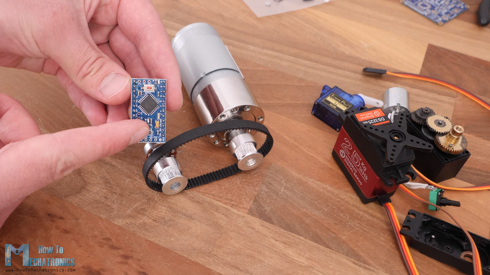
We just need a position sensor attached to the output shaft in some way and a microcontroller for driving the DC motor.
Now as for the position sensor, the simplest solution is to use a simple potentiometer just like the one we saw in the RC servos. The problem with these types of potentiometers though is that they have a limited range of rotation of only 270 degrees, which directly limits the range of rotation of the servo motor. There are also other types of potentiometers that can make multiple turns and can provide better range and resolution, but still they have limited rotation.
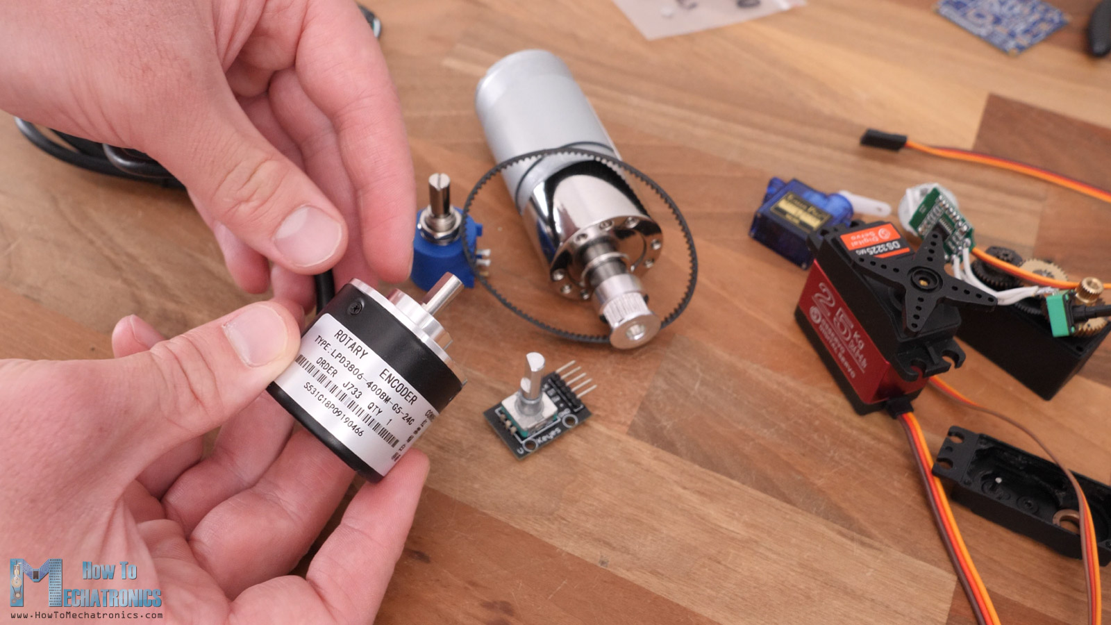
If we need the servo motor to have unlimited range of rotation, then we need to use an encoder. Encoders are electro-mechanical devices that can keep track of the angular position of the shaft with unlimited rotation. There are many types of encoders like incremental or absolute, or depending on their sensing technology optical, magnetic or capacitive. Of course, each of them has their own advantages and disadvantages.
AS5600 Encoder – Magnetic Rotary Position Sensor
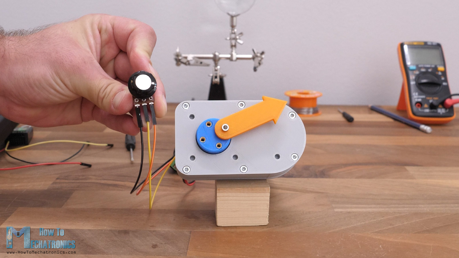
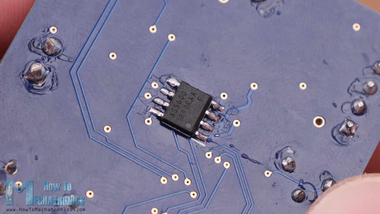
I chose to use a magnetic encoder, or the AS5600 magnetic rotary position sensor, because it is very compact and easy to implement encoder providing high precision or resolution. Just take a look at how small this microchip is.
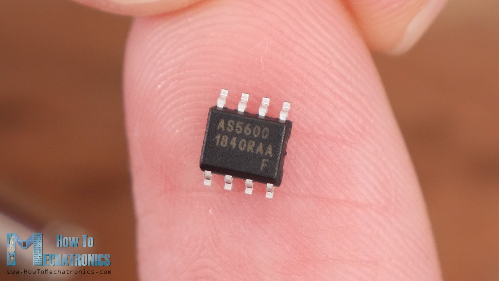
It has a built-in Hall-Effect sensor that can detect changes in the direction of magnetic field. So, we just have to attach a magnet to the output shaft of the motor and position it close the microchip at a distance from 0.5 to 3mm.
Now as the motor shaft and the magnet will rotate, the Hall-Effect sensor will capture those changes in the magnetic field direction. With the help of the built-in 12-bit A/D converter, the AS5600 sensor can output 4096 positions per turn or 360 degrees rotation.
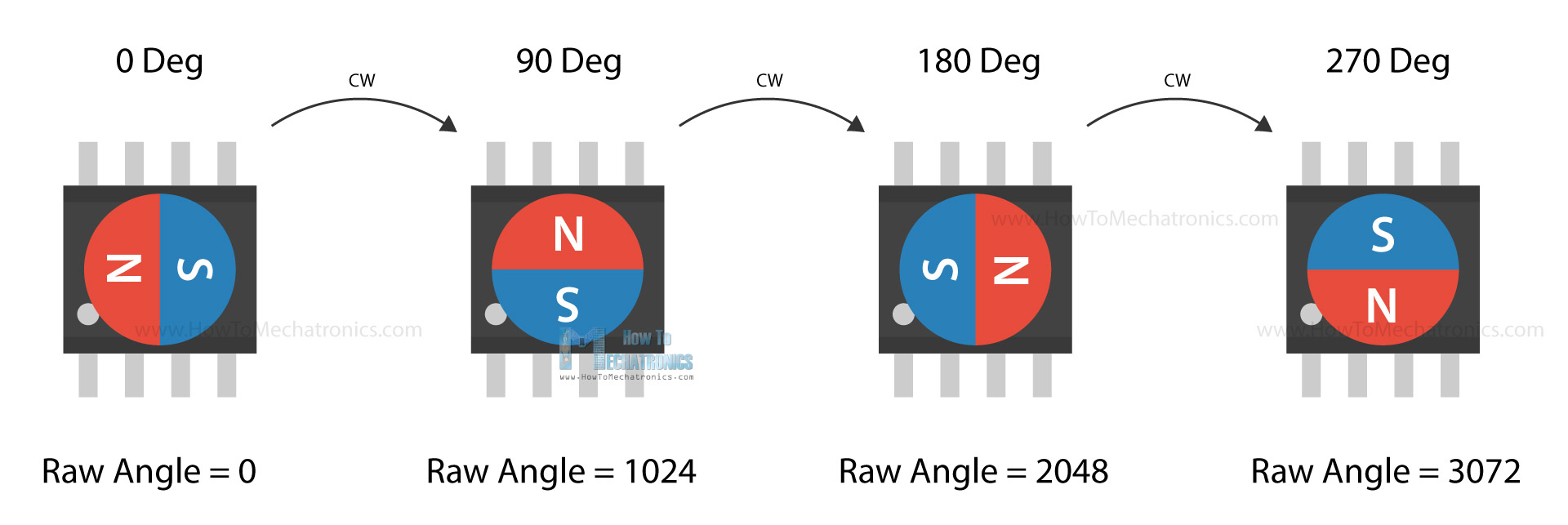
That means, it can detect changes of the angular position as small as 0.0878 degrees. That’s pretty impressive, and with the fact that it’s very affordable and easy to get, it’s the right choice for a custom-built servo motor.
All right, so what else do we need, a microcontroller and a driver for the DC motor. I chose the DRV8871 DC motor driver which can handle up to 3.5 amps of current, and the Atmega328 microcontroller.
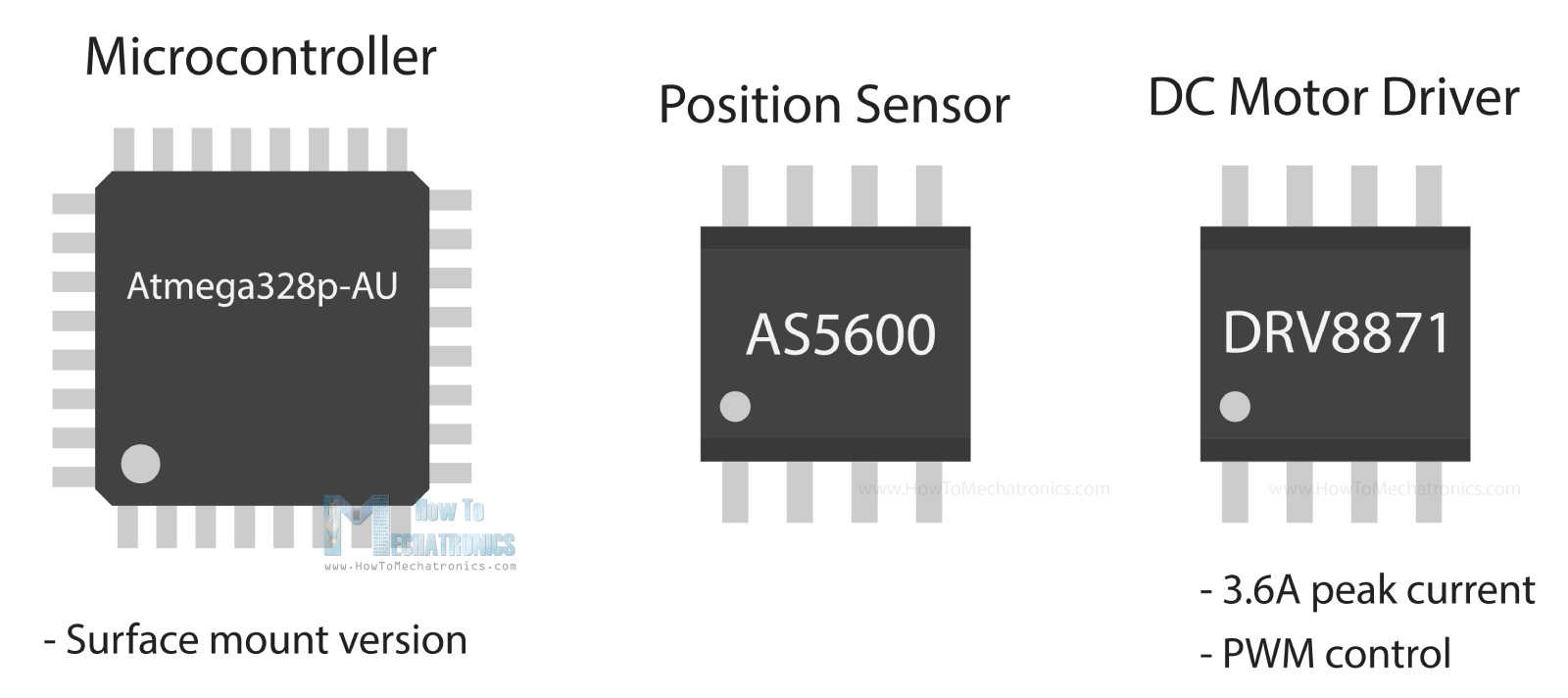
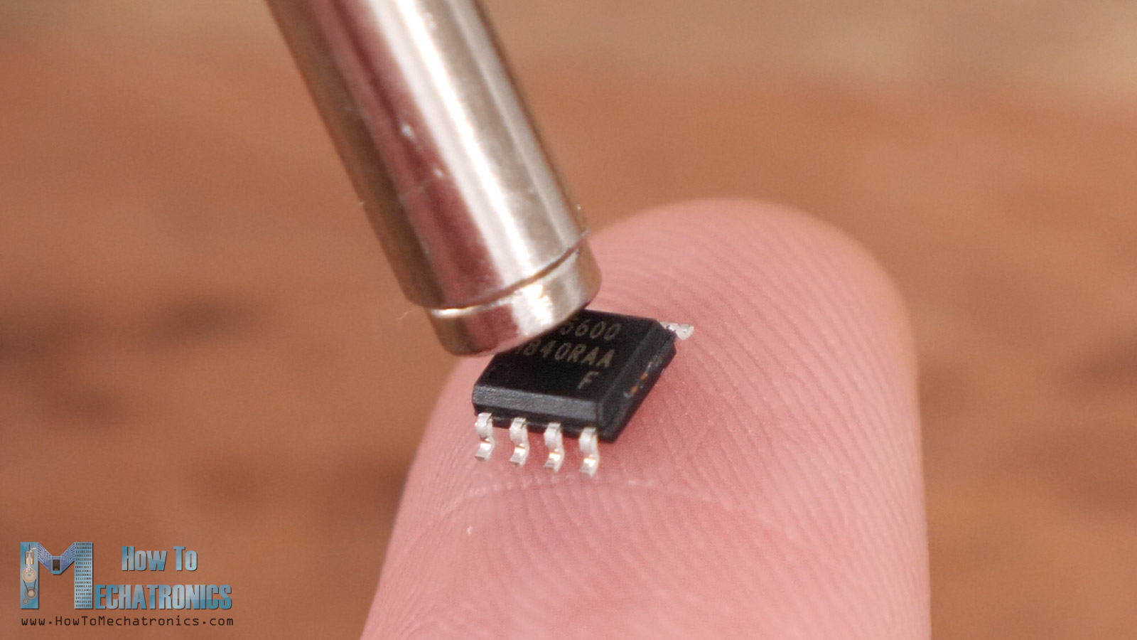
I chose the surface-mount version of it, as it’s much more compact than the DIP version, and my goal was to make as small as possible custom PCB on which I can include everything so that the servo can work as a stand-alone device.
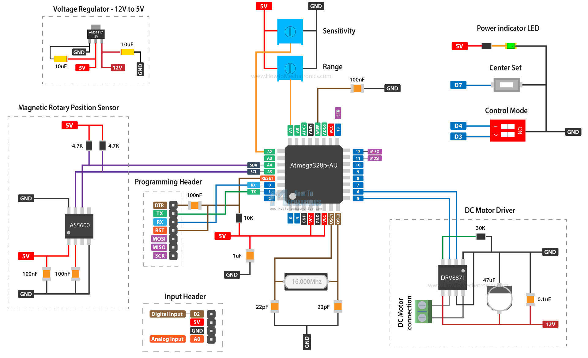
Custom Servo Motor Circuit Diagram
Here’s the complete circuit diagram of this custom-built servo motor.
You can get the components needed for this project from the links below:
- AS5600 magnetic encoder ………………….. Amazon / AliExpress
- DRV8871 DC motor driver ……………….…. Amazon / AliExpress
- Atmega328p-AU …………………………………. Amazon / AliExpress
- 16Mhz crystal oscillator …………………….. Amazon / AliExpress
- AMS1117 5V voltage regulator ………..…. Amazon / AliExpress
- 3386P square potentiometer ………………. Amazon / AliExpress
- Capacitors 0805 kit …………………………….…. Amazon / AliExpress
- 12V DC motor – ~ 50RPM …………….……. Amazon / AliExpress
Disclosure: These are affiliate links. As an Amazon Associate I earn from qualifying purchases.
So, we have the Atmega328 microcontroller along with its recommended bare minimum circuit, which includes a 16Mhz oscillator, few capacitors and a resistor.
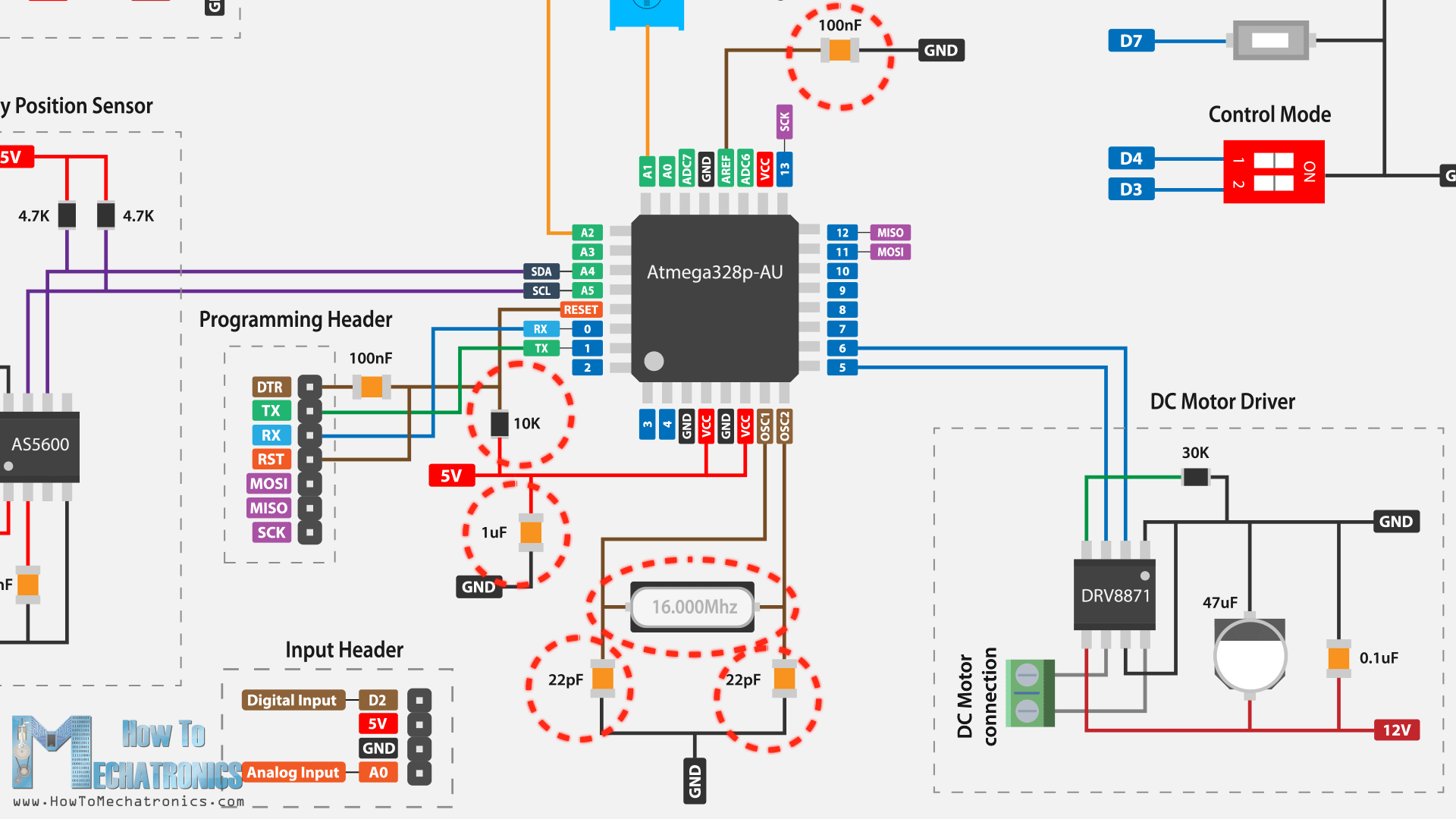
For powering the microcontroller and the other components that require 5V, we are using the AMS1117 voltage regulator, which will drop the 12V power input to 5V.
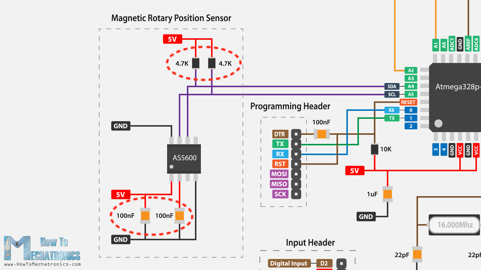
Here’s the AS5600 position sensor with its recommended circuit which includes two capacitors and two pull-up resistors for the IC2 communication.
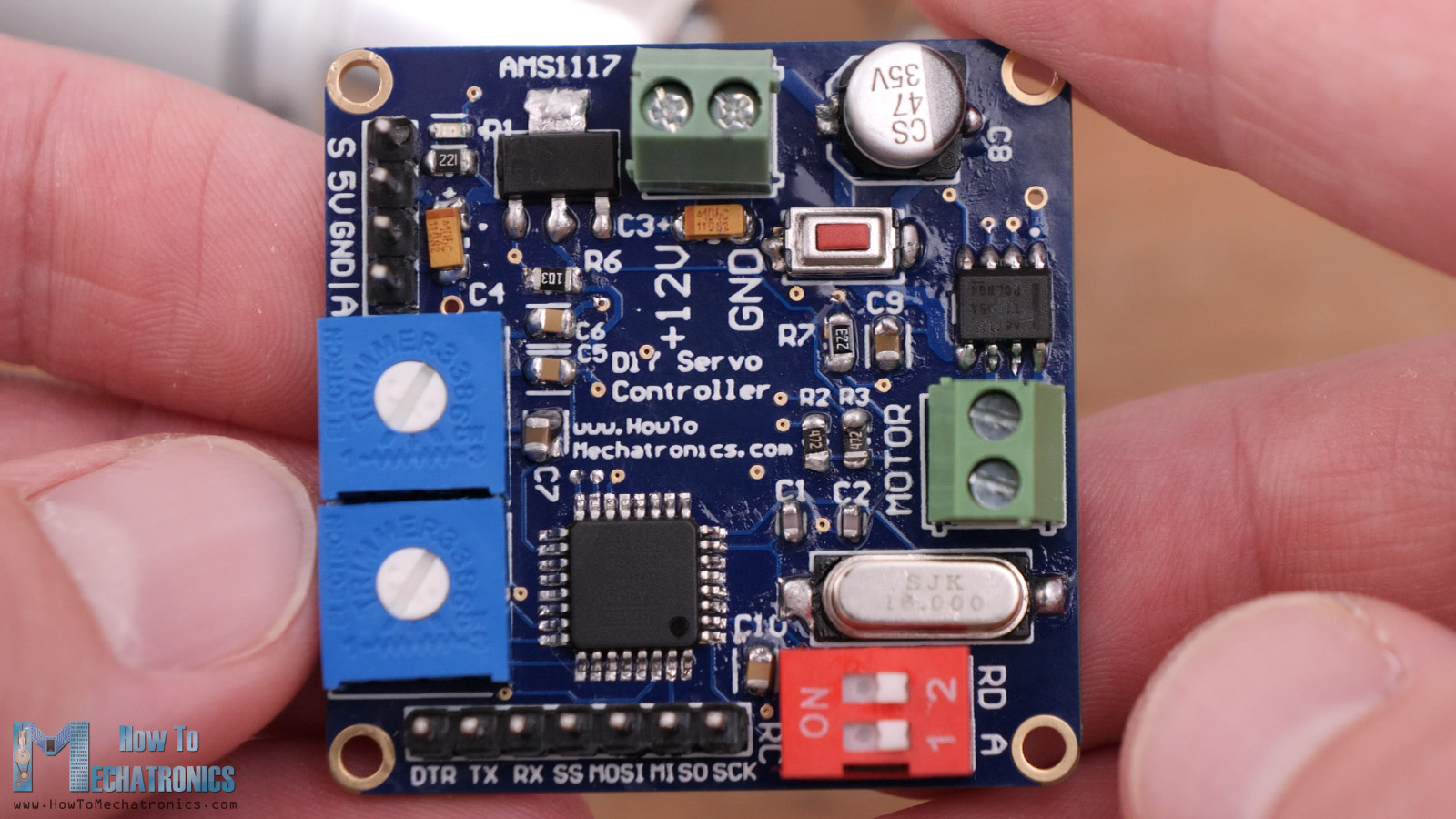
The DRV8871 DC motor driver needs just one resistor for limiting the current, and two decoupling capacitors. Then we have two potentiometers connected to the analog inputs of the microcontroller, one for adjusting the range of rotation and the other for adjusting the sensitivity of the servo. The push button is used for setting the center point of the servo, and the two-way dip switch for selecting the working modes of the servo. There’s a pin header for the inputs of the servo, either analog voltage input or a digital PWM input from an RC receiver, along with a 5V and a ground pin. There’s also a pin header for programming the microcontroller through the SPI protocol and the serial port.
Here’s a recap of this circuit and its workflow. The input, or the desired angular position, is received through these two pins and it can be either an analog voltage coming from a potentiometer or a digital PWM signal coming from an RC receiver. The input goes into the microcontroller where it is compared to the actual angular position that is detected by the encoder, or the AS5600 position sensor. This sensor communicates with the microcontroller through the IC2 protocol.
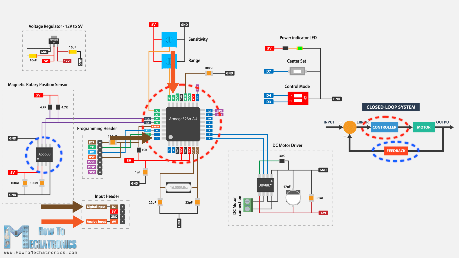
Then the microcontroller does the math, it calculates the error and according to it, it sends PWM signal to the DRV8871 driver which drives the DC motor until it reaches that desired position.
The whole circuit is powered by 12V, and the AS1117 voltage regulator provides 5V for the microcontroller and the other components appropriately.
PCB Design
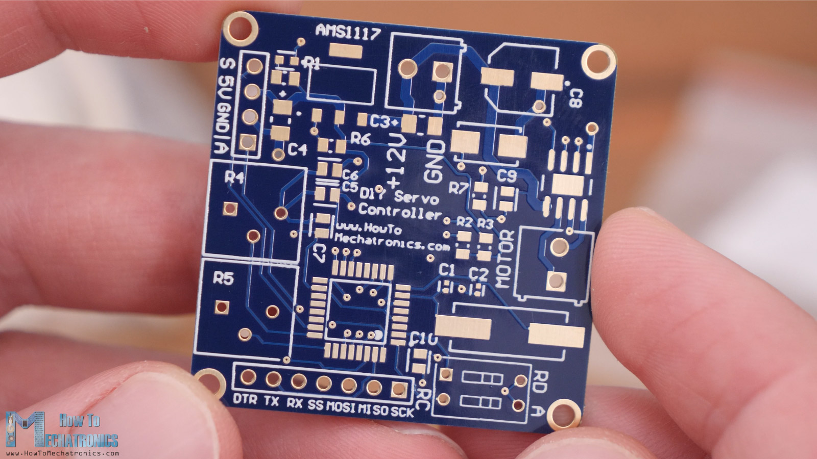
According to the circuit diagram, I tried to design the PCB as small as possible, and it came out to be 40x40mm.
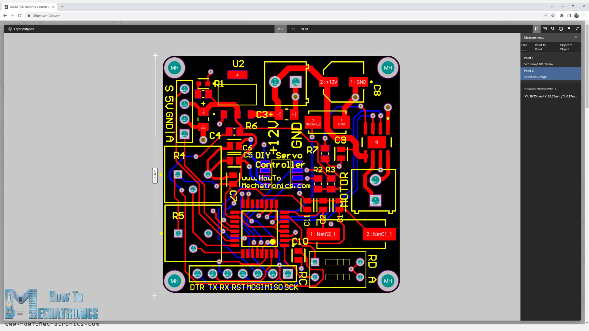
I position the encoder at the bottom side and exactly at center point of the PCB, so that it can be easily mounted and aligned with the output shaft of the servo.
All other components are located on the other side so that they won’t interfere with the encoder and the output shaft.
I ordered the PCB from PCBWay. Here we can simply upload the Gerber file, choose the properties of our PCB, and order it at a reasonable price.
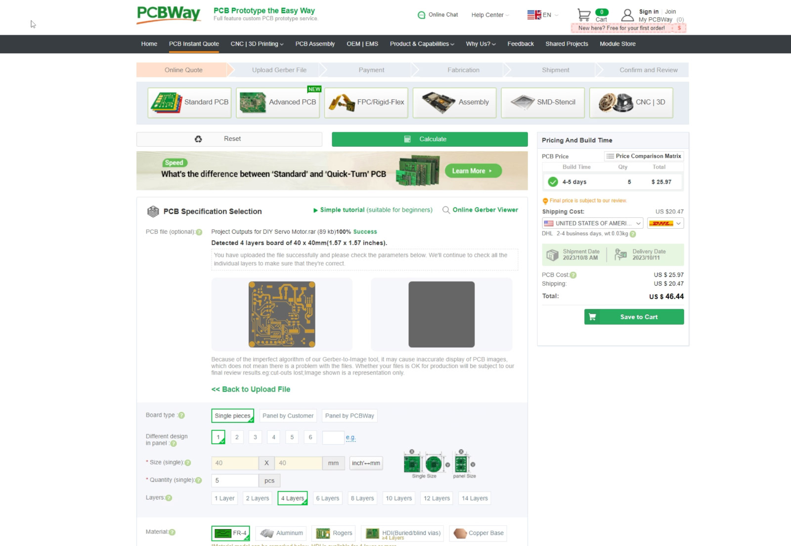
I designed the PCB to have 4 layers, the middle ones are for GND, which increases the price a bit. I didn’t change any of the default properties except for the PCB color which I chose to be white, and I tick that I accept change for the Surface finish to Immersion gold if applicable without extra charge.
You can find and download the Gerber from the PCBWay projects sharing community through which you can also directly order the PCB.
Nevertheless, after several days the PCB arrived. The quality of the PCB is great, everything is the same as in the design, and I got it in immersion gold surface finish.
All right, so now we can move on with soldering the components to it. I started with the smaller components like this indicator LED, and the capacitors and the resistors.
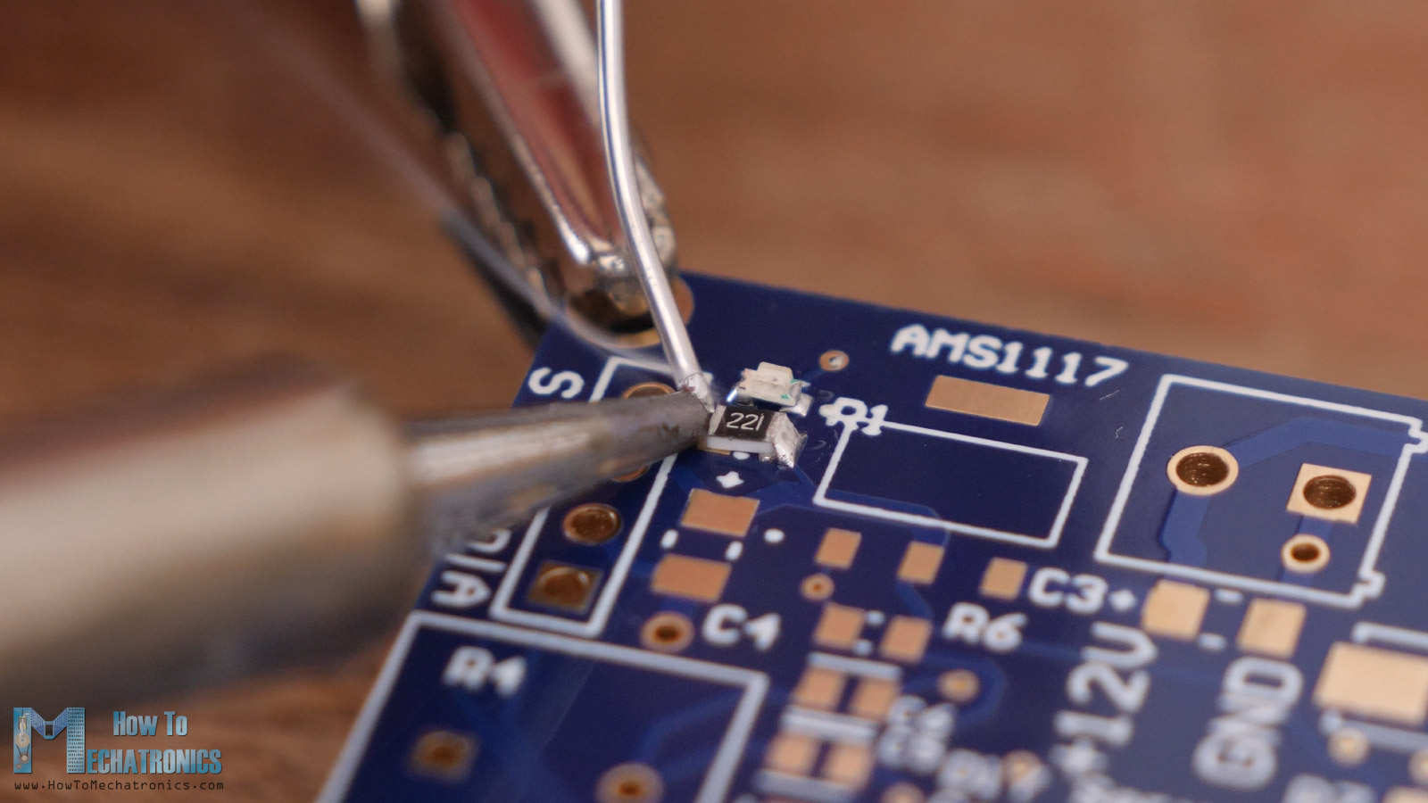
This is actually my first time soldering this small SMD components, and I was really, really bad at it.
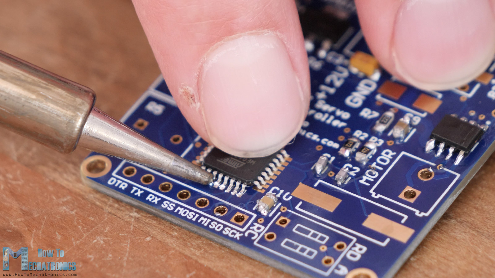
The most challenging was soldering the Atmega328 microcontroller, as the pins are really small and very close to each other, but I somehow managed to do it.
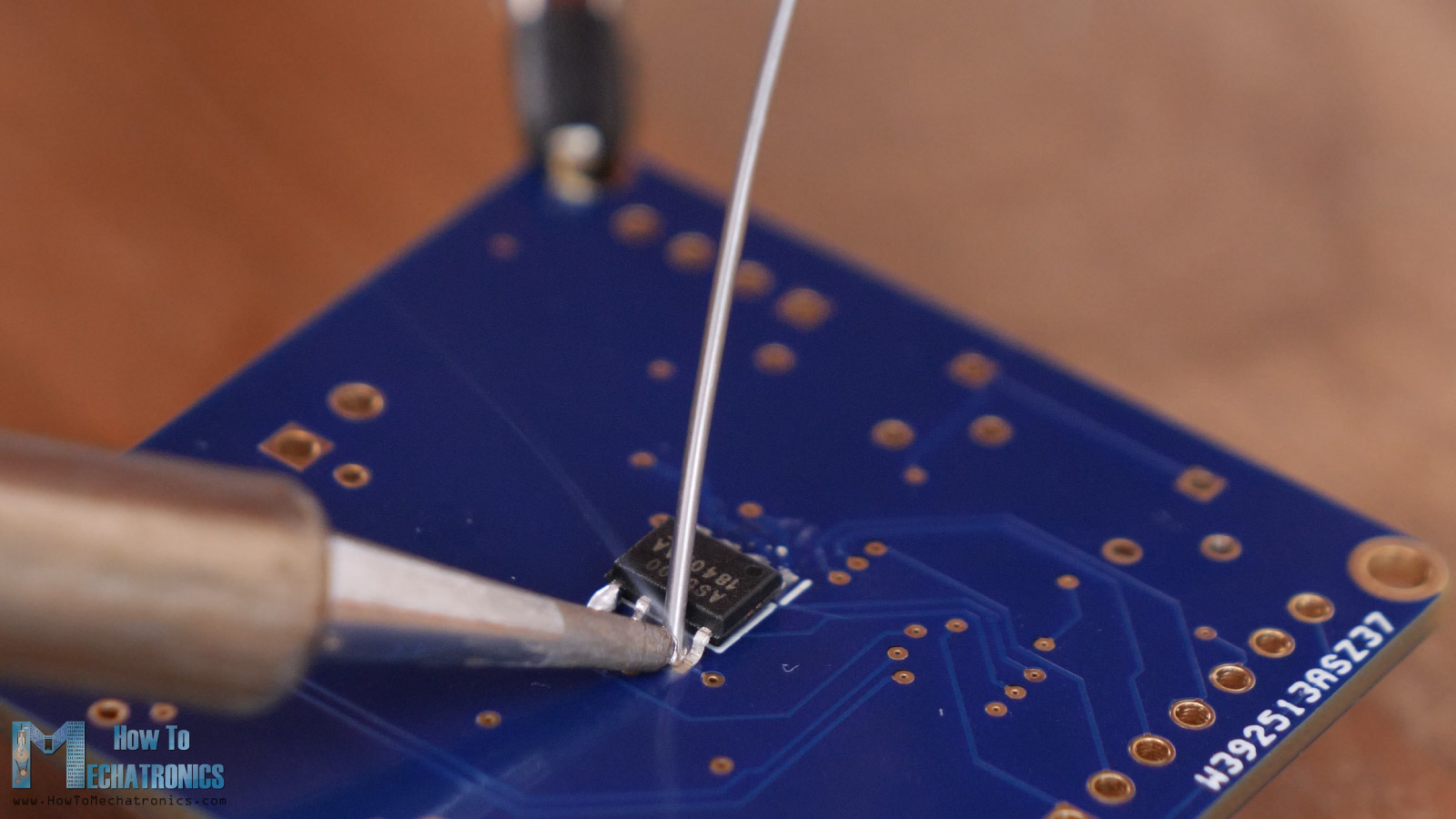
The AS5600 encoder microchip was easy to solder on the back side of the PCB, as well as the bigger, through-hole components, like the dip switch, the potentiometers, the terminal blocks and the pin headers.
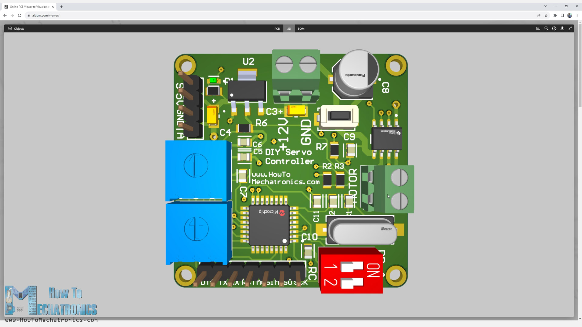
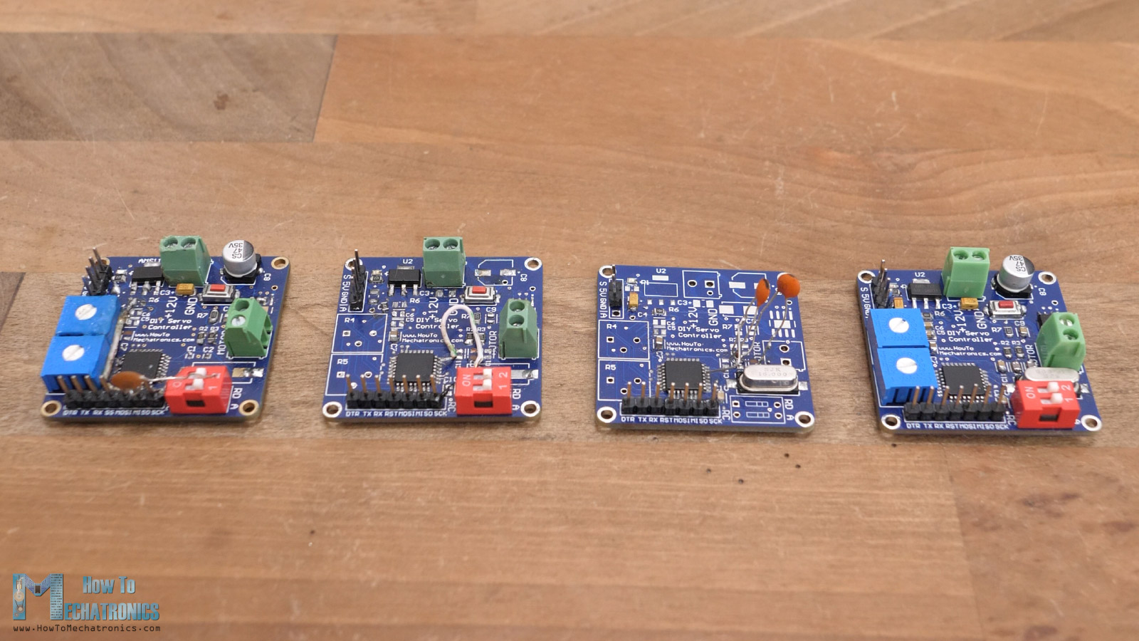
Anyway, here’s the final appearance of the controller board which after all, it turned out decent, I think.

Now it’s time to make a suitable gearbox for the DC motor and this controller board.
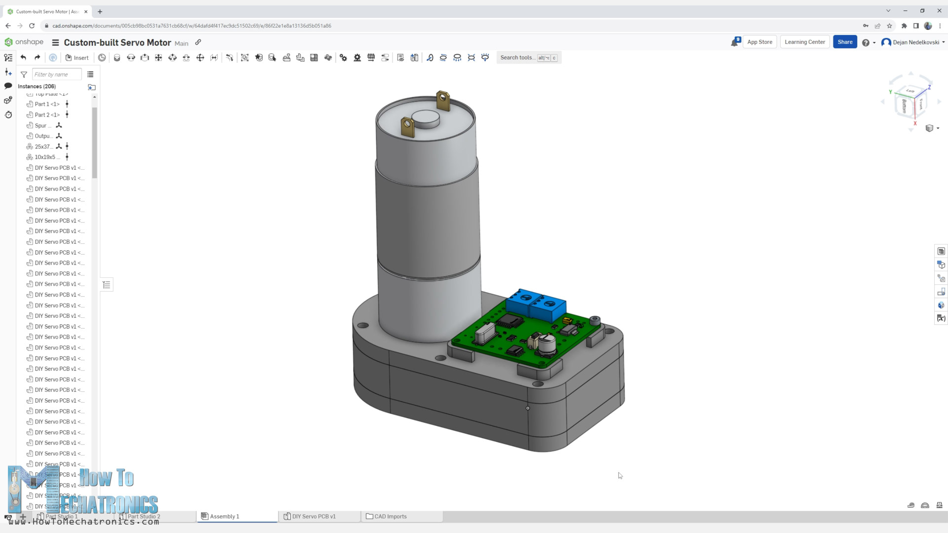
Custom Servo 3D Model
I designed the gearbox for this custom servo motor using Onshape. The design of the gearbox depends on the DC motor of course. As I mentioned we can use any size DC motor in combination with the controller board we just made.
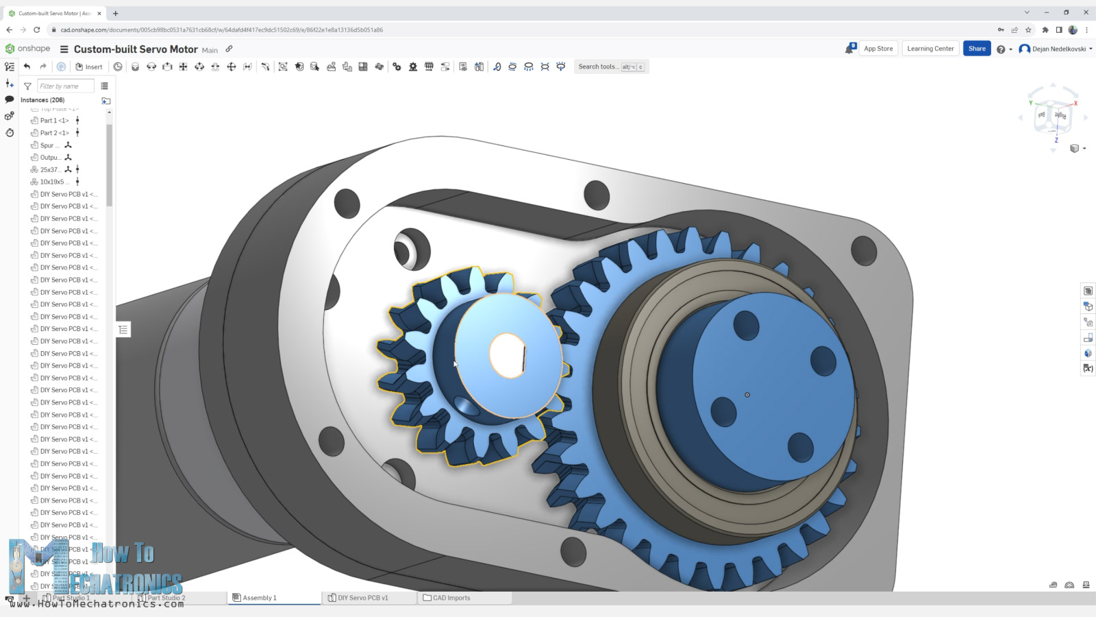
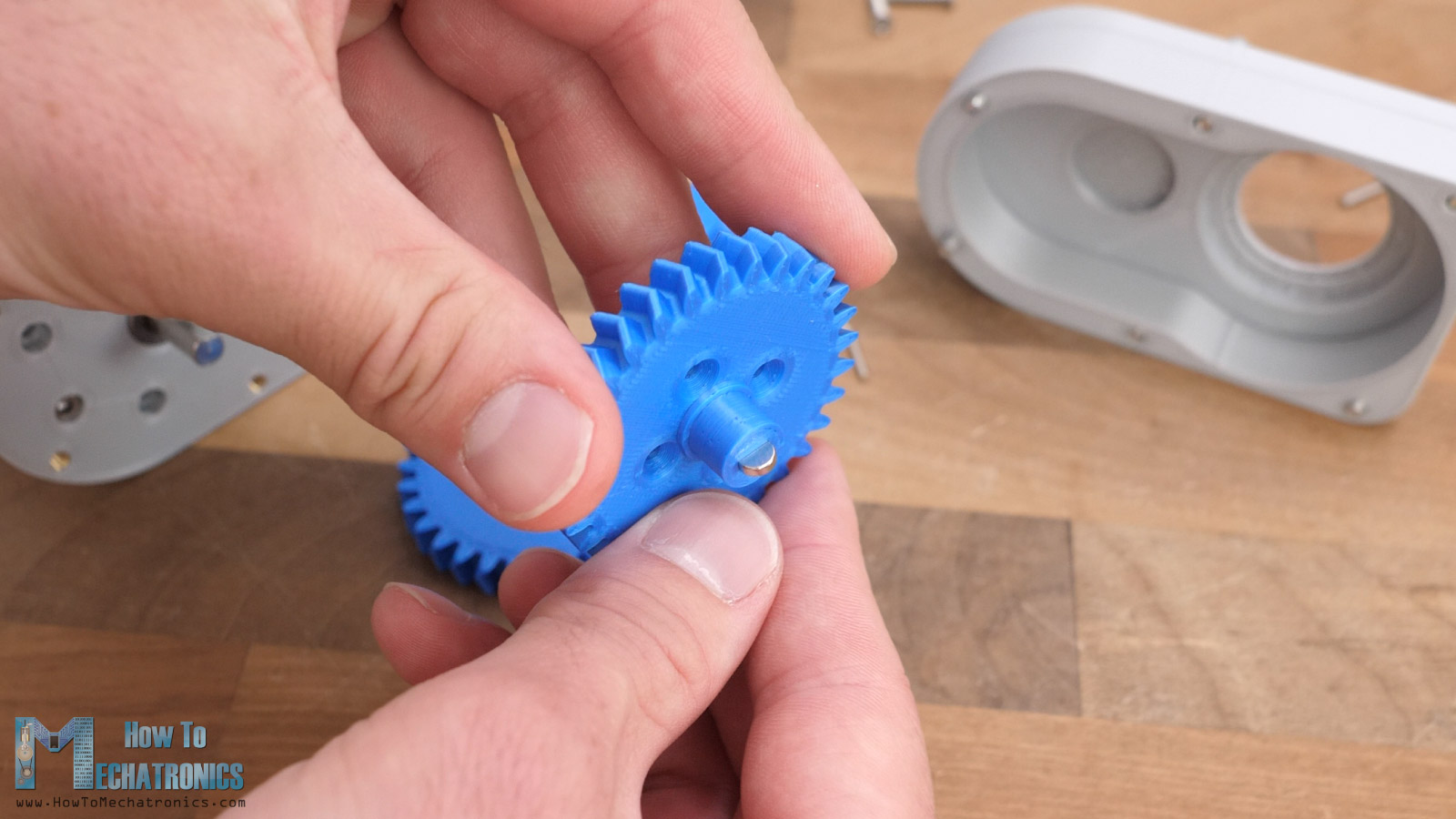
Here I’m using a DC motor with 37mm diameter and a built-in gearbox that outputs 50RPM. 50RPM is good speed for a servo motor, but I wanted to go a bit lower than that, to get better torque, so I made a gearbox with 3 times reduction. I used herringbone gears for that purpose as they are efficient and easy to make with a 3D printer.
Of course, here we have the freedom to make this gearbox design however we want, as it depends on the DC motor that we want to use and what output speeds we want to get.
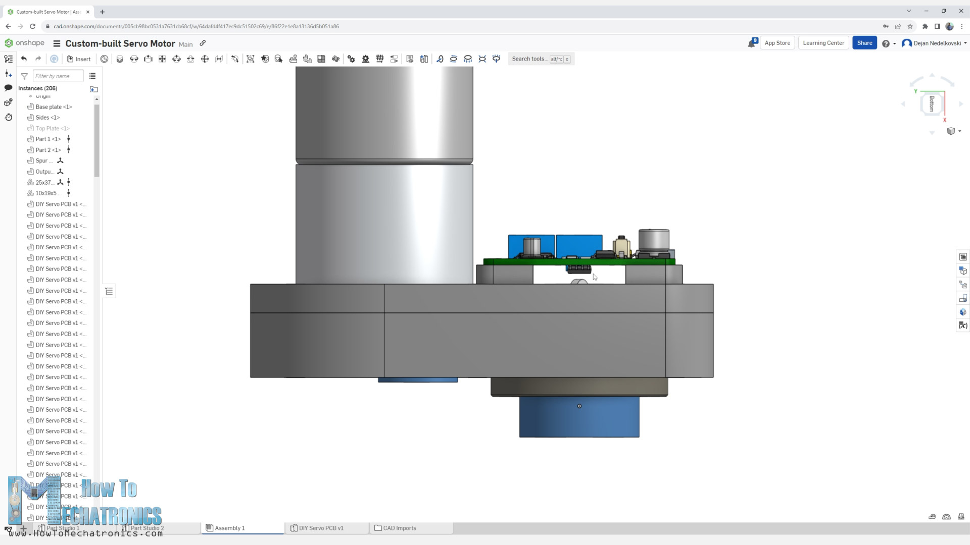
I positioned the controller board on the back side of this gearbox and aligned it perfectly in the center of the output shaft.
In case we want to use the DC motor shaft directly as an output, we can just use 1:1 gearset so that we can track the position of the shaft correctly. Or we could also use a belt system in such a case. Like I said, we have endless possibilities for making the gearbox.
Download 3D Model and STL Files
You can view and explore the 3D model of this custom-built servo motor directly on your web-browser with Onshape. (You need an Onshape account for that, you can create a free account for at home use)
Of course, you also download 3D model, as well as the STL files need for 3D printing the parts from here:
STEP file:
STL files for 3D Printing:
Assembling the custom servo
Here are the 3D printed parts for this build so we can start assembling the servo motor.
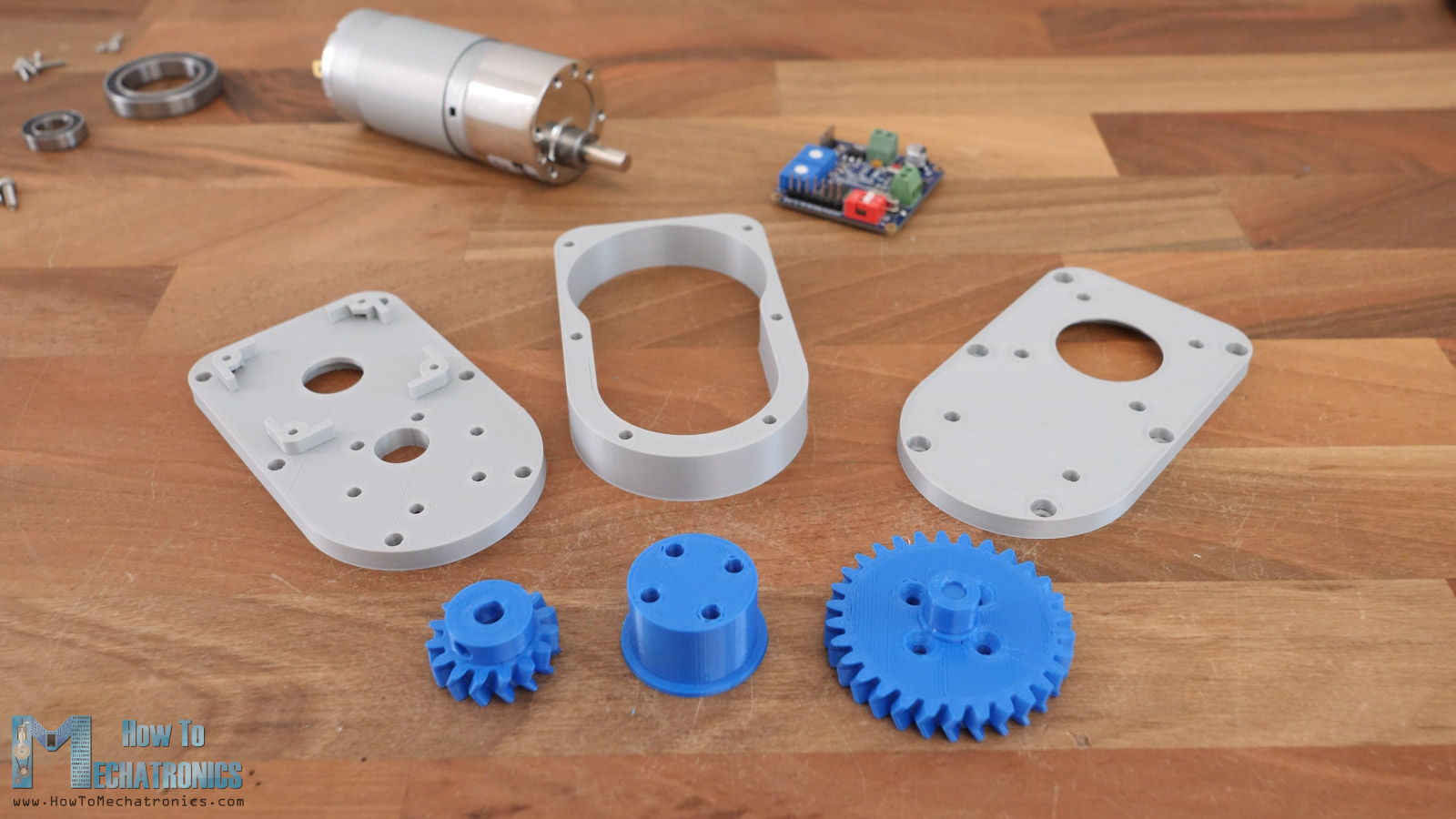
Along with them we need some M3 bolts and threaded inserts, and some bearings.
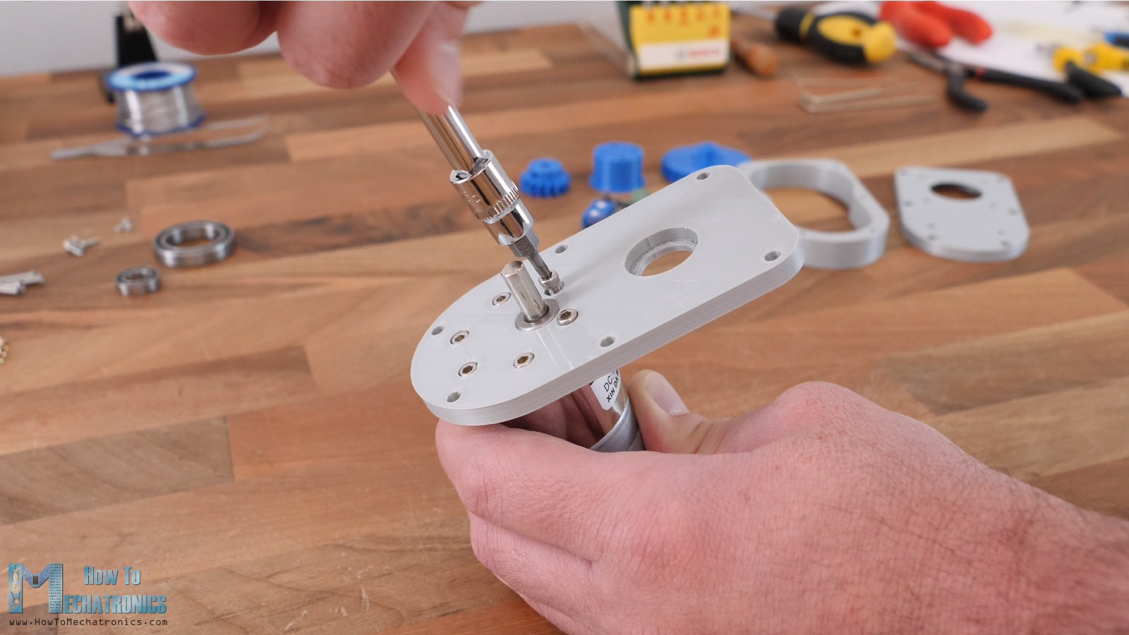
First, I secured the DC motor to the base plate with some M3 bolts with 8mm length.
Then we can install the two gears in place. The smaller gear goes directly to the DC motor shaft, and the bigger gear will be the output of the servo. Though, the output shaft of the is composed of two parts.
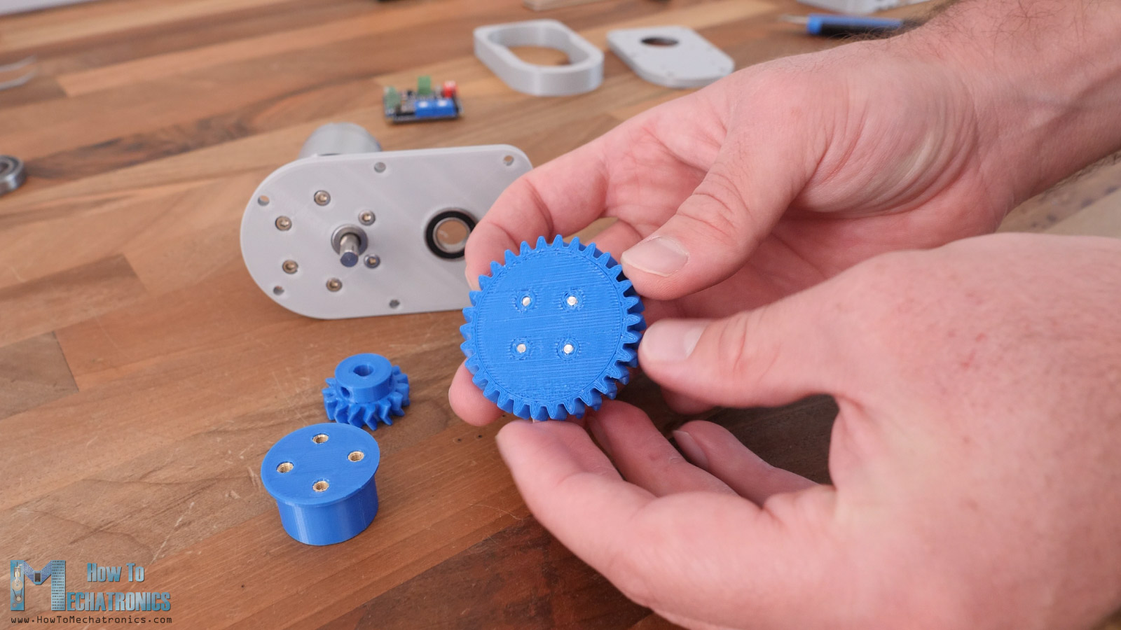
I installed threaded inserts on both sides of this output shaft part, on one side for connecting the gear to it, and on the other side for attaching things on the output of the servo.
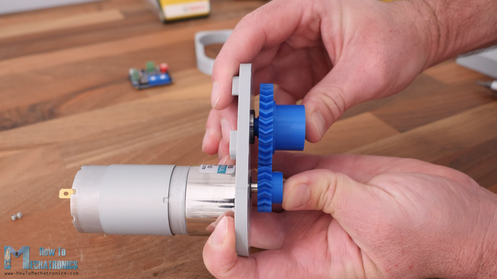
I also installed threaded inserts to the smaller gear which will be used for securing it to the DC motor shaft. Now we can slide the pared gears into their position. As these are herringbone gears, we must slide them both in place at the same time, otherwise we cannot pair them if we insert them one by one.
Using a grub screw, I secured the small gear to the DC motor shaft. I applied 12V to the DC motor to check whether the gearset will work properly.
We can finish the gearbox assembling by inserting the side panel, the ball bearing for the output shaft and the top cover.
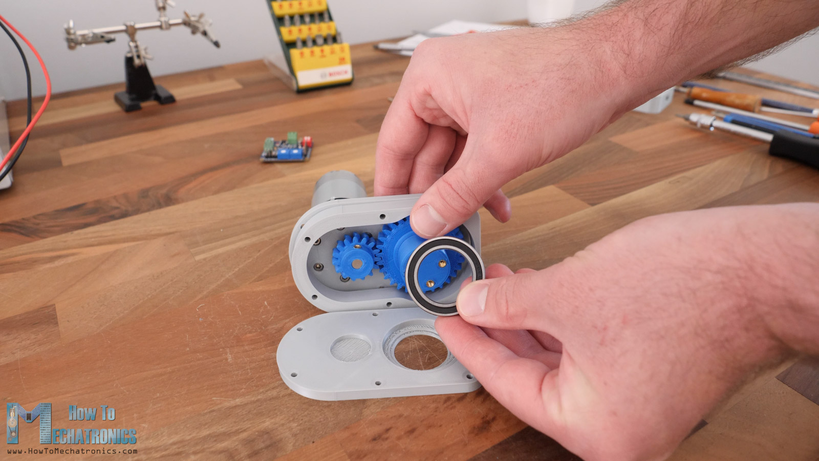
I installed some M3 threaded inserts on the back plate so we can secure the whole assembly with some 20mm long M3 bolts. I tested the gearbox again, it works great. We can notice how the output shaft rotates on the back side and here we need to insert the magnet that the AS5600 encoder will keep track of.
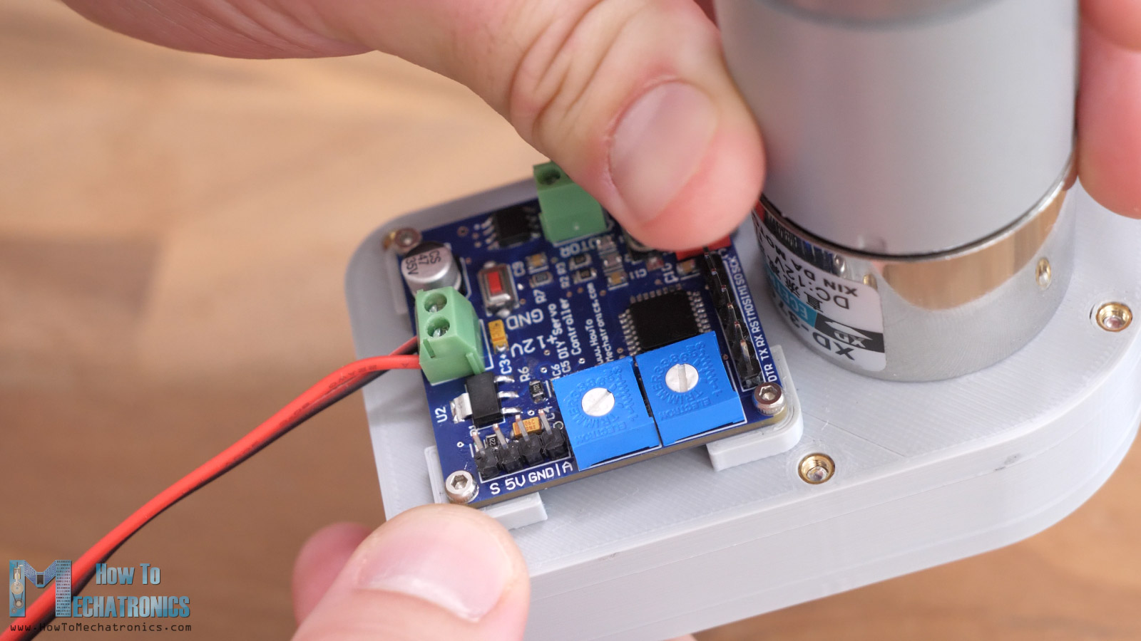
We secure the controller board to the gearbox using some M2 bolts and nuts. The AS5600 position sensor is now perfectly aligned with the magnet and so when the output shaft will rotate it will measure the change in the magnetic field properly.
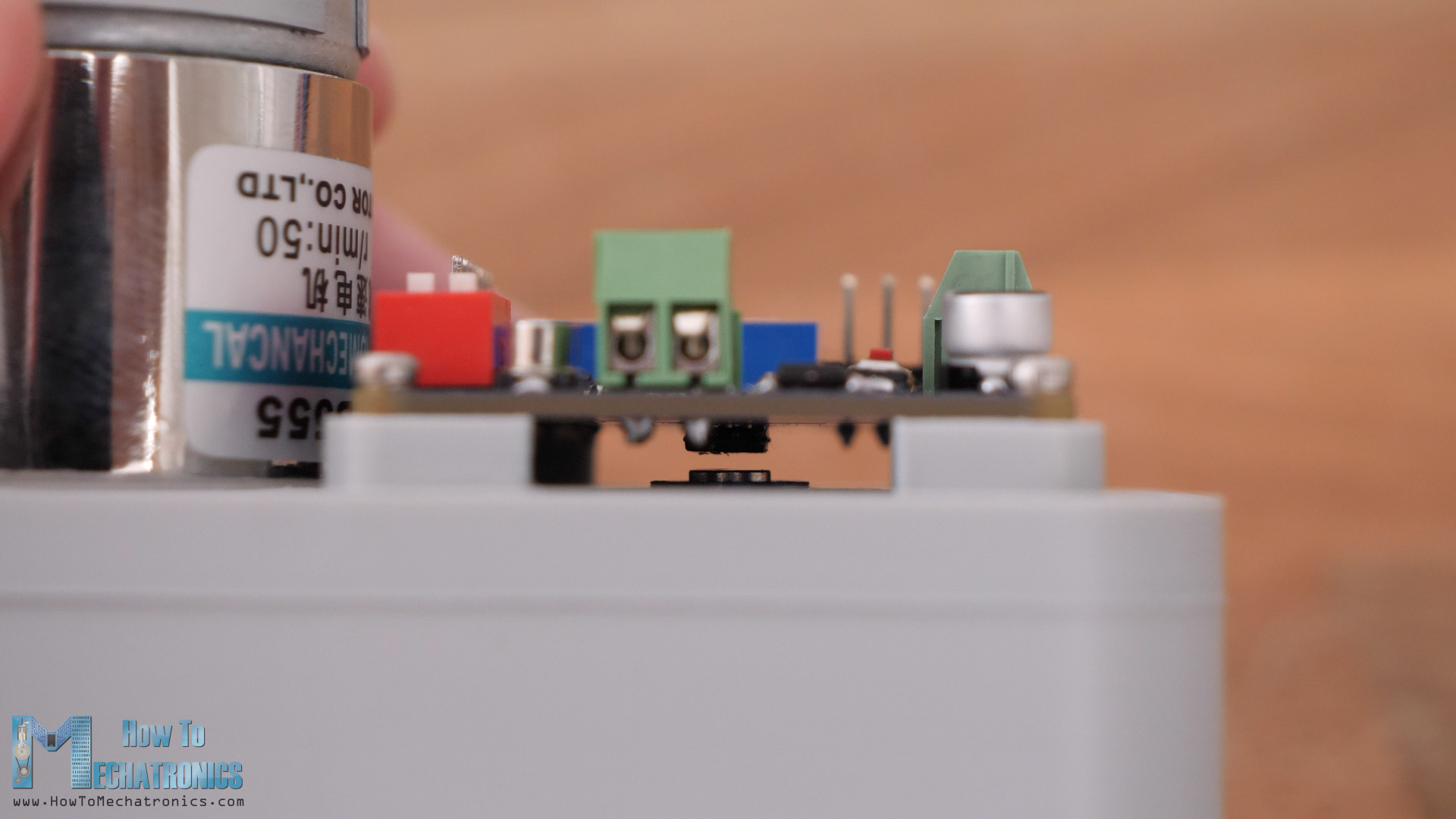
Please note here that the magnetization direction of the permanent magnet is very important. Depending on whether it’s axially or diametrically magnetized, we should position the magnet either perpendicular or parallel to that AS5600 IC.
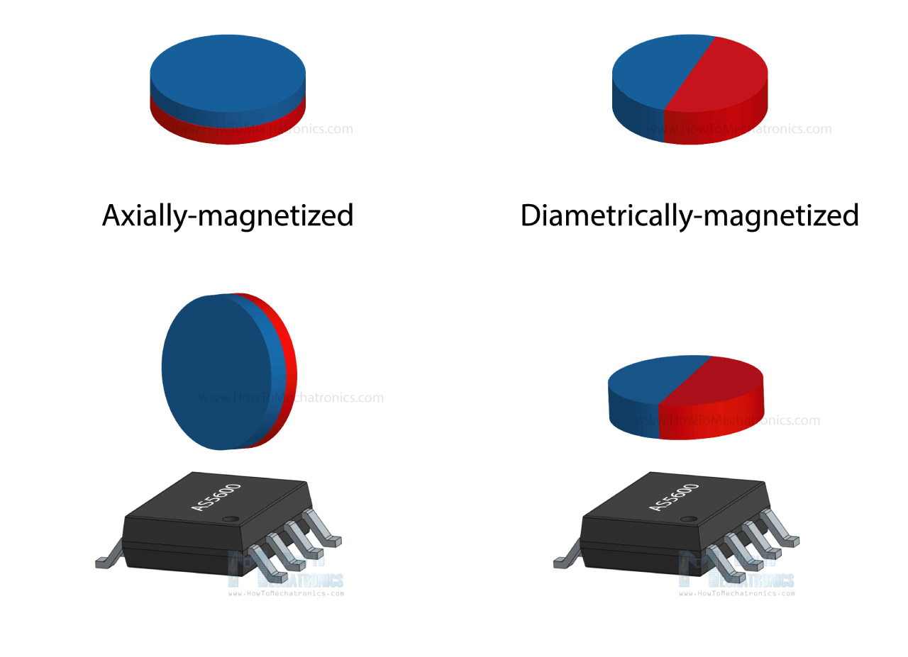
I ended up changing the direction of my magnet, as it didn’t have the right magnetization so that the AS5600 encoder could measure it.
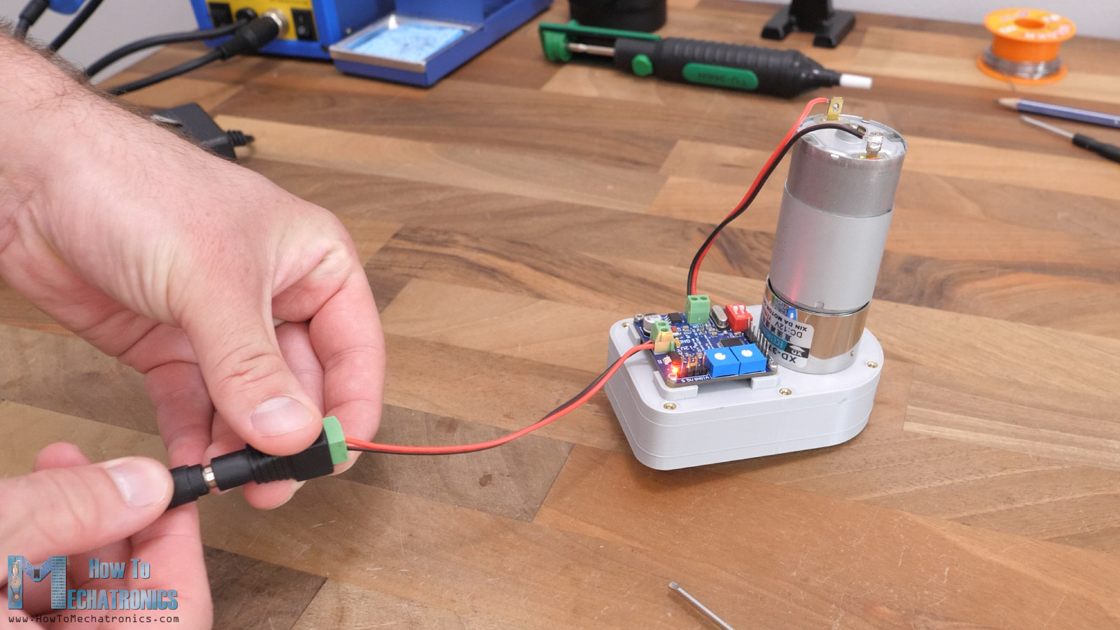
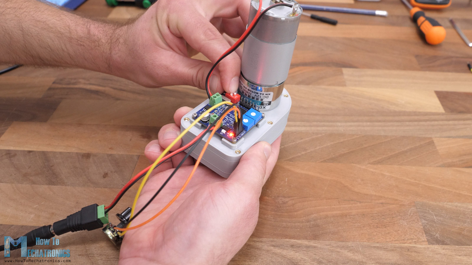
Next, I soldered two wires to the DC motor and connected the motor to the controller with the terminal block. As for the power, I connected two wires to the power terminal block, which on the other side have a DC power connector for connecting a 12V power supply. And that’s it, our custom-built servo motor is done.
Programming the Controller
What’s left to do now is to give life to this servo, or program the controller. For that purpose, first we need to burn a bootloader to the ATmega328p microcontroller. Without a bootloader the microcontroller won’t be able to understand the language or the code that we will send to it.
Bootloader Burn
To burn the bootloader to the ATmega328p, we need an Arduino board, in my case I will use an Arduino Nano board.
We will use the SPI communication, so we need to connect the suitable SPI pins on the Arduino board and our controller board.
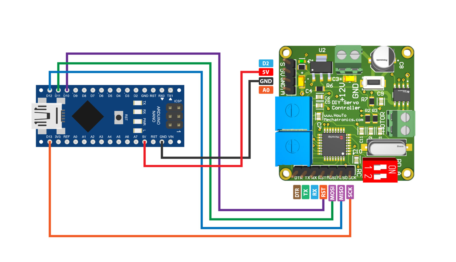
Now, using the Arduino IDE, we need to open the ArduinoISP example sketch and upload it to the Arduino Nano board. With this code the Arduino Nano is now capable of burning the bootloader to the ATmega328 microcontroller.
Next, from the Tools menu, as a Programmer we need to select Arduino as ISP and then click Burn Bootloader.
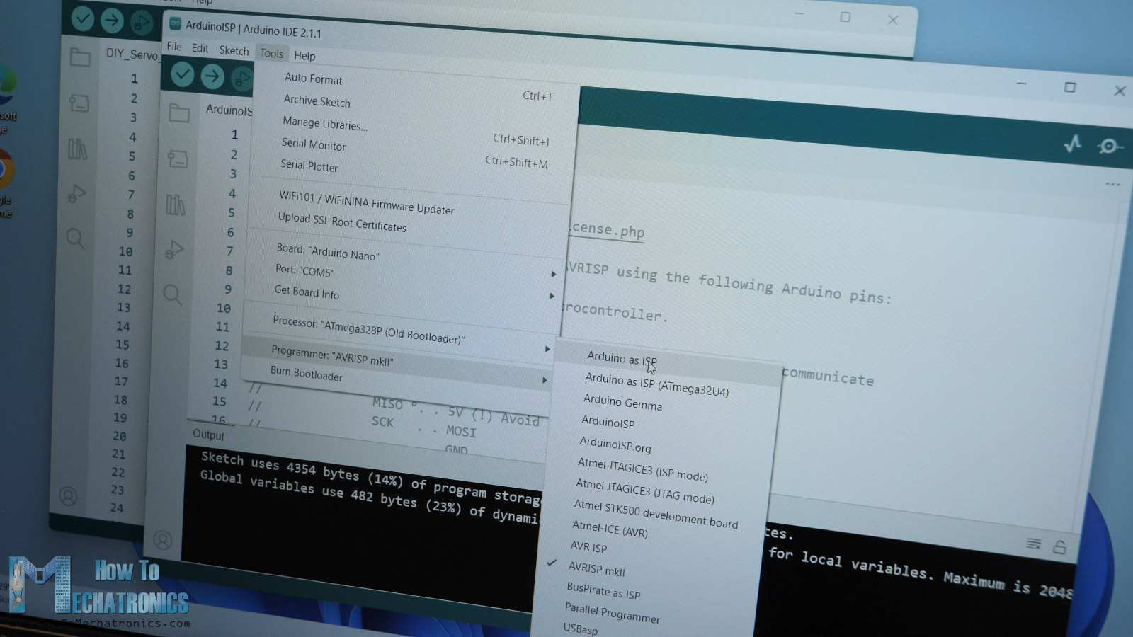
While burning the bootloader, we should notice that the Arduino NANO lights will blink a lot, and that will result in successful bootloader burn.
Code Upload
Once we are done with that, now we can program or upload the code to the controller board with the help of an USB to UART Interface module.
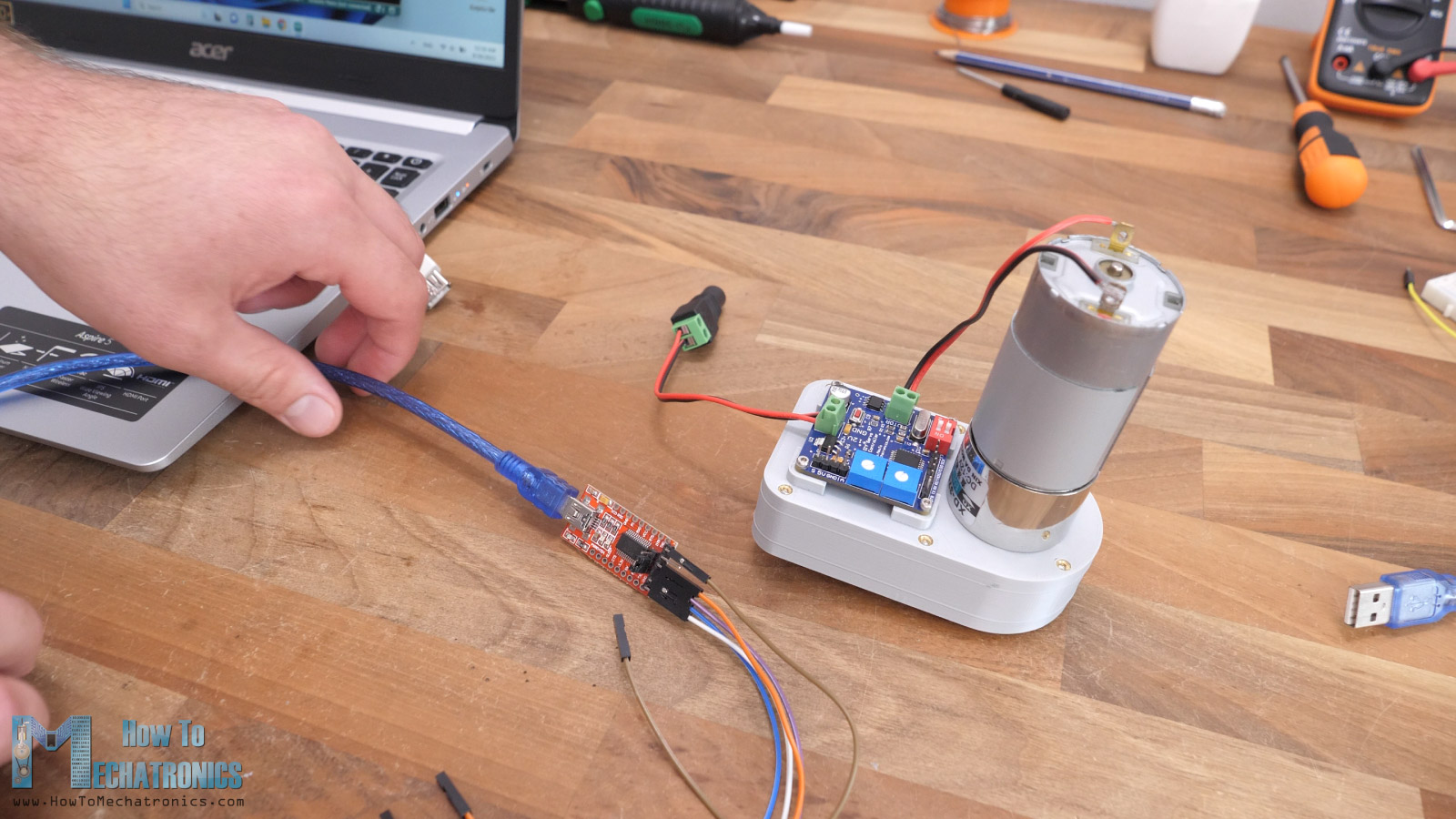
The controller board has dedicated pins for easily connecting them just like shown in this circuit diagram.
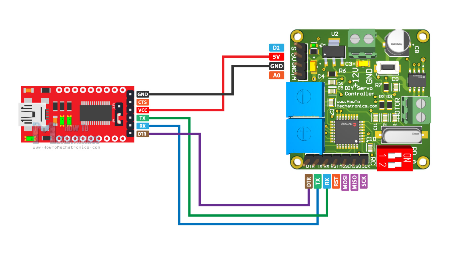
Now we can open the code for this custom-built servo that I made and upload it to the controller. Before we do that though, we should first install the libraries for the AS5600 sensor and the PID control. We can easily do that from the Arduino IDE Library Manager. Once we hit the upload button the code will be written to our ATmega328 controller through the USB to UART Interface module.
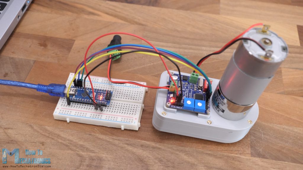
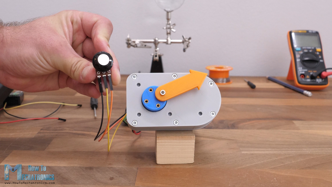
And that’s it, our custom-build servo motor is done. Now we can connect a potentiometer to it to test it out. Just a note that the analog input goes to the “S” pin on the controller board, instead of the “A” pin.
When designing the PCB, I’ve connected these two pins wrongly to the ATmega328. Then we can select the analog input mode through the DIP switch and power the servo.
And here it is, we can control the servo motor position with the help of the analog input from the potentiometer. We have successfully converted our DC motor into a servo motor.
Source Code
Now let’s take a look at the code of this custom-built servo motor.
/*
 *    Custom-built Servo Motor - Arduino Code
 *    by Dejan, www.HowToMechatronics.com
 *
 *   Libraries:
 *   AS5600 encoder: https://github.com/RobTillaart/AS5600
 *   PID conroller: https://github.com/br3ttb/Arduino-PID-Library/blob/master/PID_v1.h
 */


#include "AS5600.h"
#include "Wire.h"
#include <PID_v1.h>


AS5600 as5600;   //  use default Wire

double Pk1 = 2;  //speed it gets there
double Ik1 = 0;
double Dk1 = 0.025;

//Define Variables we'll be connecting to
double Setpoint, Input, Output;

PID myPID(&Input, &Output, &Setpoint, Pk1, Ik1, Dk1, DIRECT);

#define motor_IN1 5
#define motor_IN2 6
#define ch1 2
#define centerSet 7
#define inputSwitch 3
#define modeSwitch 4

int ch1Value;

int encoderValue, inputValue, pwmValue;
String inString = "";  // string to hold input

int centerAngle = 2047; // 180 degrees
int angleDifference = 0;
int angleValue = 0;
int leftLimit = 30;
int rightLimit = 4067;
int rangeAdjustment = 0;
float sensitivityAdjustment = 0;
float angle = 0;

int quadrantNumber = 2;
int previousQuadrantNumber = 3;
int numberOfTurns = 0;
float totalAngle = 0;

int error = 0;

char incomingByte = 0;
int intInput = 0;

void setup() {
  Serial.begin(115200);
  Serial.println(__FILE__);
  Serial.print("AS5600_LIB_VERSION: ");
  Serial.println(AS5600_LIB_VERSION);

  Wire.begin();

  pinMode(motor_IN1, OUTPUT);
  pinMode(motor_IN2, OUTPUT);
  // Activate the Arduino internal pull-up resistors
  pinMode(centerSet, INPUT_PULLUP);
  pinMode(inputSwitch, INPUT_PULLUP);
  pinMode(4, INPUT_PULLUP);

  myPID.SetMode(AUTOMATIC);              // PID Setup
  myPID.SetOutputLimits(-255, 255);
  myPID.SetSampleTime(20);

}

void loop() {
  // Read encoder value - current position
  encoderValue = as5600.readAngle();

  // Continuous rotation mode
  if (digitalRead(modeSwitch) == 0) {
    // Enter desired angle for the servo to go to through the serial monitor
    while (Serial.available() > 0) {
      int inChar = Serial.read();
      if (isDigit(inChar)) {
        // convert the incoming byte to a char and add it to the string:
        inString += (char)inChar;
      }
      // if you get a newline, print the string, then the string's value:
      if (inChar == '\n') {
        Setpoint = inString.toInt(); // Setpoint - desired angle
        // clear the string for new input:
        inString = "";
      }
    }
    if (digitalRead(inputSwitch) == 0) { // Potentiometer as input
      inputValue = analogRead(A0);
      if (inputValue < 400) {
        Setpoint = Setpoint - 0.3;
      }
      if (inputValue < 300) {
        Setpoint = Setpoint - 0.3;
      }
      if (inputValue < 200) {
        Setpoint = Setpoint - 0.3;
      }

      if (inputValue > 600) {
        Setpoint = Setpoint + 0.3;
      }
      if (inputValue > 700) {
        Setpoint = Setpoint + 0.3;
      }

      if (inputValue > 800) {
        Setpoint = Setpoint + 0.3;
      }
    }
    else if (digitalRead(inputSwitch) == 1) {
      inputValue = pulseIn(ch1, HIGH, 30000); // RC receiver as input
      if (inputValue < 1450) {
        Setpoint--;
      }
      if (inputValue < 1350) {
        Setpoint--;
      }
      if (inputValue < 1250) {
        Setpoint--;
      }
      if (inputValue < 1150) {
        Setpoint--;
      }
      if (inputValue > 1550) {
        Setpoint++;
      }
      if (inputValue > 1650) {
        Setpoint++;
      }
      if (inputValue > 1750) {
        Setpoint++;
      }
      if (inputValue > 1850) {
        Setpoint++;
      }
    }

    // Convert encoder RAW values into angle value
    angle = encoderValue * 0.087890625;
    // Quadrant 1
    if (angle >= 0 && angle <= 90) {
      quadrantNumber = 1;
    }
    // Quadrant 2
    if (angle >= 90 && angle <= 180) {
      quadrantNumber = 2;
    }
    // Quadrant 3
    if (angle >= 180 && angle <= 270) {
      quadrantNumber = 3;
    }
    // Quadrant 4
    if (angle >= 270 && angle <= 360) {
      quadrantNumber = 4;
    }

    if (quadrantNumber != previousQuadrantNumber) {
      // Transition from 4th to 1st quadrant
      if (quadrantNumber == 1 && previousQuadrantNumber == 4) {
        numberOfTurns++;
      }
      // Transition from 1st to 4th quadrant
      if (quadrantNumber == 4 && previousQuadrantNumber == 1) {
        numberOfTurns--;
      }
      previousQuadrantNumber = quadrantNumber;
    }
    if (totalAngle >= 0) {
      totalAngle = (numberOfTurns * 360) + angle;
    }
    else {
      totalAngle = (numberOfTurns * 360) + angle;
    }

    // Establish Input value for PID
    Input = totalAngle;
  }

  // Limited Rotation Mode
  else if (digitalRead(modeSwitch) == 1) {

    rangeAdjustment = analogRead(A1);
    leftLimit = 0 + 30 + rangeAdjustment;
    rightLimit = 4097 - 30 - rangeAdjustment;


    if (digitalRead(inputSwitch) == 0) {  // Analog input - Potentiometer
      // Get value from potentiometer
      inputValue = analogRead(A0);
      if (inputValue < 15) {
        inputValue = 15;
      }
      if (inputValue > 1008) {
        inputValue = 1008;
      }
      Setpoint = map(inputValue, 15, 1008, -255, 255);
    }
    else if (digitalRead(inputSwitch) == 1) {  // Digital input - RC transmitter
      inputValue = pulseIn(ch1, HIGH, 30000); // Read RC receiver as input
      Setpoint = map(inputValue, 1000, 2000, -255, 255);
    }

    // Set center angle
    if (digitalRead(centerSet) == LOW) {
      centerAngle = encoderValue;
      angleDifference = 2047 - encoderValue;
      delay(1000);
    }
    // Adjust angle value according to the center point (angleDifference)
    if (centerAngle < 2047) {
      angleValue = encoderValue + angleDifference;
      if (encoderValue < 4097 && encoderValue > (4096 - angleDifference)) {
        angleValue = encoderValue - 4097 + angleDifference;
      }
    }
    if (centerAngle > 2047) {
      angleValue = encoderValue + angleDifference;
      if (encoderValue >= 0 && encoderValue < abs(angleDifference)) {
        angleValue = encoderValue + 4097 + angleDifference;
      }
    }
    else if (centerAngle == 2047) {
      angleValue = encoderValue;
    }

    // Establish Input value for PID
    Input = map(angleValue , leftLimit, rightLimit, -255, 255);
  }
  // Adjusting sensitivity
  Pk1 = analogRead(A2) * 0.002;
  myPID.SetTunings(Pk1, Ik1, Dk1);

  // Run PID process to get Output value
  myPID.Compute();
  // Move right
  if (Output > 1 ) {
    pwmValue = Output;

    if (pwmValue < 30 && pwmValue > 5) {
      pwmValue = pwmValue + 30;
    }
    if (pwmValue <= 5) {
      pwmValue = 0;
    }
    digitalWrite(motor_IN1, LOW);
    analogWrite(motor_IN2, pwmValue);
  }
  // Move left
  else if (Output < 1 ) {
    pwmValue = abs(Output);

    if (pwmValue < 30 && pwmValue > 5) {
      pwmValue = pwmValue + 30;
    }
    if (pwmValue <= 5) {
      pwmValue = 0;
    }
    analogWrite(motor_IN1, pwmValue);
    digitalWrite(motor_IN2, LOW);
  }
  // Do not move
  else if (Output > -1 && Output < 1) {
    pwmValue = 0;
    digitalWrite(motor_IN1, LOW);
    digitalWrite(motor_IN2, LOW);
  }

  //Serial.print(Setpoint);
  //Serial.print("\t");
  //Serial.println(totalAngle);
}Code language: PHP (php)
Code Overview
So, we start the loop by reading the encoder value or the current position of the shaft.
// Read encoder value - current position
  encoderValue = as5600.readAngle();Code language: JavaScript (javascript)
Then if we are in Continuous rotation mode, we accept values from the serial monitor and use them as a setpoint or desired angle for the PID controller.
// Enter desired angle for the servo to go to through the serial monitor
    while (Serial.available() > 0) {
      int inChar = Serial.read();
      if (isDigit(inChar)) {
        // convert the incoming byte to a char and add it to the string:
        inString += (char)inChar;
      }
      // if you get a newline, print the string, then the string's value:
      if (inChar == '\n') {
        Setpoint = inString.toInt(); // Setpoint - desired angle
        // clear the string for new input:
        inString = "";
      }
    }Code language: JavaScript (javascript)
If the input mode is set to potentiometer, we read its analog input, and correct the setpoint value depending how far we turn it.
if (digitalRead(inputSwitch) == 0) { // Potentiometer as input
      inputValue = analogRead(A0);
      if (inputValue < 400) {
        Setpoint = Setpoint - 0.3;
      }
      if (inputValue < 300) {
        Setpoint = Setpoint - 0.3;
      }
      if (inputValue < 200) {
        Setpoint = Setpoint - 0.3;
      }

      if (inputValue > 600) {
        Setpoint = Setpoint + 0.3;
      }
      if (inputValue > 700) {
        Setpoint = Setpoint + 0.3;
      }

      if (inputValue > 800) {
        Setpoint = Setpoint + 0.3;
      }
    }Code language: JavaScript (javascript)
We do the same setpoint correction if the input is the RC receiver.
Here we convert the RAW encoder values into angle values, and with these if statements we keep track in which quadrant the current position of the shaft is.
// Convert encoder RAW values into angle value
    angle = encoderValue * 0.087890625;
    // Quadrant 1
    if (angle >= 0 && angle <= 90) {
      quadrantNumber = 1;
    }
    // Quadrant 2
    if (angle >= 90 && angle <= 180) {
      quadrantNumber = 2;
    }
    // Quadrant 3
    if (angle >= 180 && angle <= 270) {
      quadrantNumber = 3;
    }
    // Quadrant 4
    if (angle >= 270 && angle <= 360) {
      quadrantNumber = 4;
    }Code language: HTML, XML (xml)
With this information, we can keep track of how the shaft rotates and when it will make a full turn. The total angle is the Input value for the PID controller.
if (quadrantNumber != previousQuadrantNumber) {
      // Transition from 4th to 1st quadrant
      if (quadrantNumber == 1 && previousQuadrantNumber == 4) {
        numberOfTurns++;
      }
      // Transition from 1st to 4th quadrant
      if (quadrantNumber == 4 && previousQuadrantNumber == 1) {
        numberOfTurns--;
      }
      previousQuadrantNumber = quadrantNumber;
    }
    if (totalAngle >= 0) {
      totalAngle = (numberOfTurns * 360) + angle;
    }
    else {
      totalAngle = (numberOfTurns * 360) + angle;
    }

    // Establish Input value for PID
    Input = totalAngle;Code language: JavaScript (javascript)
On the other hand, if we are in limited rotation mode, first we read the potentiometer value which is used for adjusting the range of rotation and adjust the left and right limit of rotation accordingly.
rangeAdjustment = analogRead(A1);
    leftLimit = 0 + 30 + rangeAdjustment;
    rightLimit = 4097 - 30 - rangeAdjustment;
If the input mode is the potentiometer, we use its value as a setpoint value for the PID controller.
if (digitalRead(inputSwitch) == 0) {  // Analog input - Potentiometer
      // Get value from potentiometer
      inputValue = analogRead(A0);
      if (inputValue < 15) {
        inputValue = 15;
      }
      if (inputValue > 1008) {
        inputValue = 1008;
      }
      Setpoint = map(inputValue, 15, 1008, -255, 255);
    }Code language: HTML, XML (xml)
If the input mode is the RC receiver, we read the incoming PWM value from the receiver and use that value as a setpoint.
else if (digitalRead(inputSwitch) == 1) {  // Digital input - RC transmitter
      inputValue = pulseIn(ch1, HIGH, 30000); // Read RC receiver as input
      Setpoint = map(inputValue, 1000, 2000, -255, 255);
    }Code language: JavaScript (javascript)
For setting a different center point, we check whether we have pressed the push button and capture that position as a new center point.
// Set center angle
    if (digitalRead(centerSet) == LOW) {
      centerAngle = encoderValue;
      angleDifference = 2047 - encoderValue;
      delay(1000);
    }Code language: JavaScript (javascript)
According to it, then we have to adjust the actual readings from the encoder and offset them by the angle difference between the new and the old center point. We use that value as an input value for the PID controller.
if (centerAngle > 2047) {
      angleValue = encoderValue + angleDifference;
      if (encoderValue >= 0 && encoderValue < abs(angleDifference)) {
        angleValue = encoderValue + 4097 + angleDifference;
      }
    }
    else if (centerAngle == 2047) {
      angleValue = encoderValue;
    }

    // Establish Input value for PID
    Input = map(angleValue , leftLimit, rightLimit, -255, 255);Code language: HTML, XML (xml)
Using the analog input from the other potentiometer we adjust the proportional gain of the PID controller, and finally we run the PID process to get an output value.
// Adjusting sensitivity
  Pk1 = analogRead(A2) * 0.002;
  myPID.SetTunings(Pk1, Ik1, Dk1);

  // Run PID process to get Output value
  myPID.Compute();Code language: JavaScript (javascript)
We use that output value for driving the DC motors with PWM signal, left or right, or in still position depending on the output value from the PID controller, or depending on the error between the desired and the actual position the encoder reads.
// Move right
  if (Output > 1 ) {
    pwmValue = Output;

    if (pwmValue < 30 && pwmValue > 5) {
      pwmValue = pwmValue + 30;
    }
    if (pwmValue <= 5) {
      pwmValue = 0;
    }
    digitalWrite(motor_IN1, LOW);
    analogWrite(motor_IN2, pwmValue);
  }Code language: HTML, XML (xml)
So that would be all for this video. Please note that the code is not well optimized and there is room for improvement.
Also, if you try recreating this project, you should be prepared to troubleshoot. There are a lot of things that could go wrong, especially when soldering those small SMD components.
I didn’t get this servo working from the first try. Initially, I had some wrong connections on the PCB, then I ordered the PCB again with new updates, but still needed few more tries until I get it working.
This section of the article is still under construction, please check it a bit later….
Hello Dejan,
I was wondering what software you used to create your circuit diagrams.
Do you set them up using a piece of software and it generates the final product, or do you draw it manually using a photo editor?
My robotics team currently uses Google Drawings to create wiring diagrams but we are looking for wiring diagram software that is more efficient.
Thanks!
Same like you, the harder way, manually drawing everything.
Cheers! 🙂
Hi Dejan,
I would like to order the PCB board from the site you mentioned (PCBWay), and it asks me for the description of Layers 1 to 4. Could you kindly point me to it?
This is the request:
Please fill in the layer order from top side view to bottom side according to
the layers name in your file.
L1
L2
L3
L4
Thank you
Hi, I think you can skip that and order the PCB.