In this tutorial we will learn what is a planetary gear set and how it works, as well as explain how to design our own planetary gearbox and 3D print it so we can see it in real life and better understand how it works. At the end of the video, we will also do some backlash and torque tests to see how well it can perform being a 3D printed gearbox.
You can watch the following video or read the written tutorial below.
A planetary gear set is a unique type of gearing system which provides high torque and high efficiency in a compact design. Because of these three key features, planetary gearboxes are used in countless applications, such as in industrial machines, agricultural, medical, wind turbines, robots, automatic transmission and so on.
How Planetary Gears Work
A planetary gear set is composed of four main components. In the center there is a gear, called sun gear which is usually the input that drives the motor.
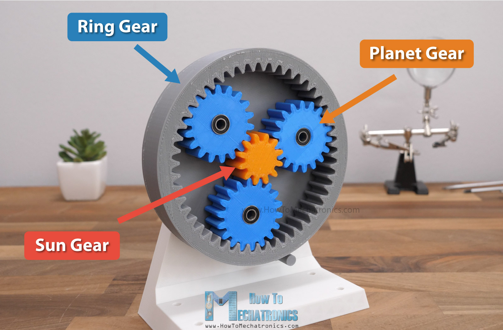
Then there are three or more gears that orbit around the sun gear which are called planet gears. The internally teethed gear is called ring gear and it determines the orbit of the planet gears.
The fourth component is called the carrier and in the most common scenario that’s the output of the gearbox.
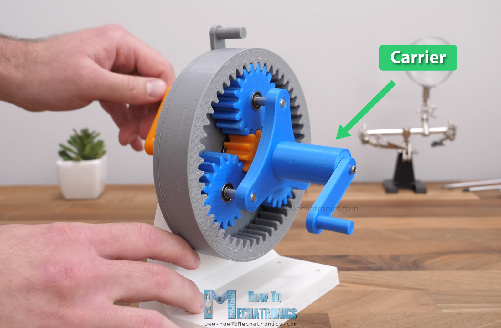
It connects the planet gears together and transfers their orbiting motion into single, central axis output.
If we rotate the sun gear, while holding the ring gear stationary, the planet carrier will rotate at a reduced speed, in this case that’s 5 times slower, or that’s 5:1 ratio.
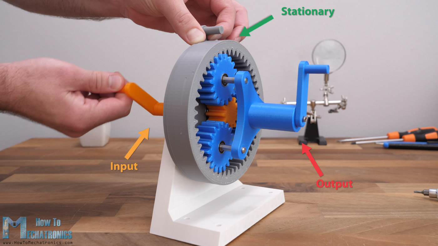
We can also use it the other way around, or use the planet carrier as an input, then the sun gear will rotate five times faster.
But that’s not all. The beauty of the planetary gearing system is that we can get various outputs or transmission ratios depending on which component is held stationary and which component is the input.
For example, we can have the carrier held stationary , and use the sun gear as input.
In such a case the output will be the ring gear which will get a different output ratio than in the pervious case, or here it will be 4 times slower and in reverse direction. That’s a negative 4:1 ratio.
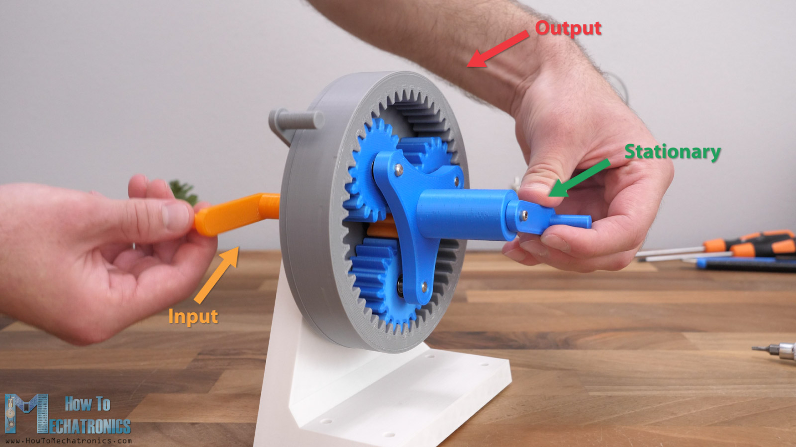
Another example would be to have the sun gear held stationary and use the ring gear as input.
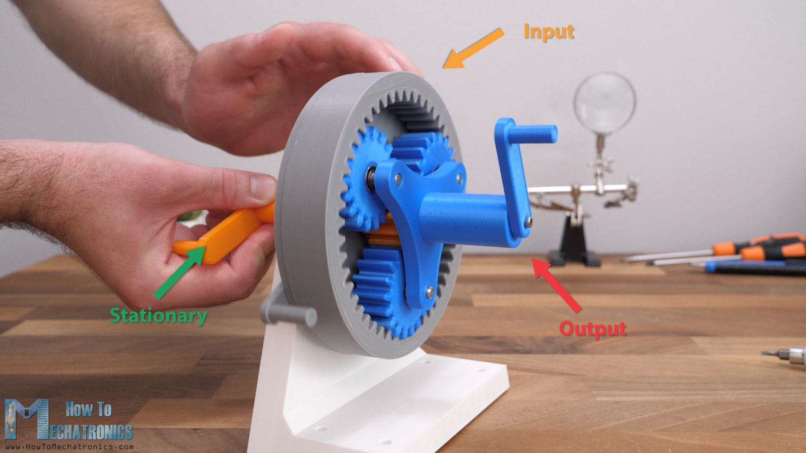
In this case the carrier will be the output and it will be 1.25 times slower than the input. That’s a ratio of 5:4.
This unique feature of the planetary gear set, to be able to produce different outputs with the same setup, is used in automatic transmissions to achieve different speeds.
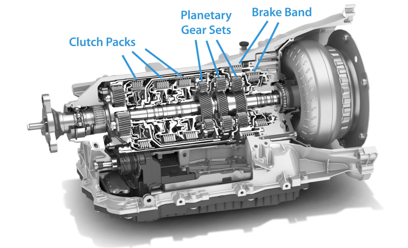
Several planetary gear sets are connected in series and with the help of some clutches that can control which component will be stationary, we can achieve the different output speeds.
Planetary Gears Transmission Ratios
The transmission ratios of a planetary gear set depend on the gear’s teeth number. Here are the formulas for calculating the transmission ratios of a planetary gear set depending on which gear is the input and which gear is held stationary.
We can see that the highest transmission ratio is achieved when the sun gear is the input, and the ring gear is held stationary. The planet carrier is the output, and the ratio is 1 + the ring gear teeth number / the sun gear teeth number.
i = 1 + Zring / Zsun
This is like I said earlier, the most common scenario for a planetary gearbox, to reduce the speed and increase the torque for industrial and construction machines, for servo motors in robotics applications and so on.
3D Printed Planetary Gearbox
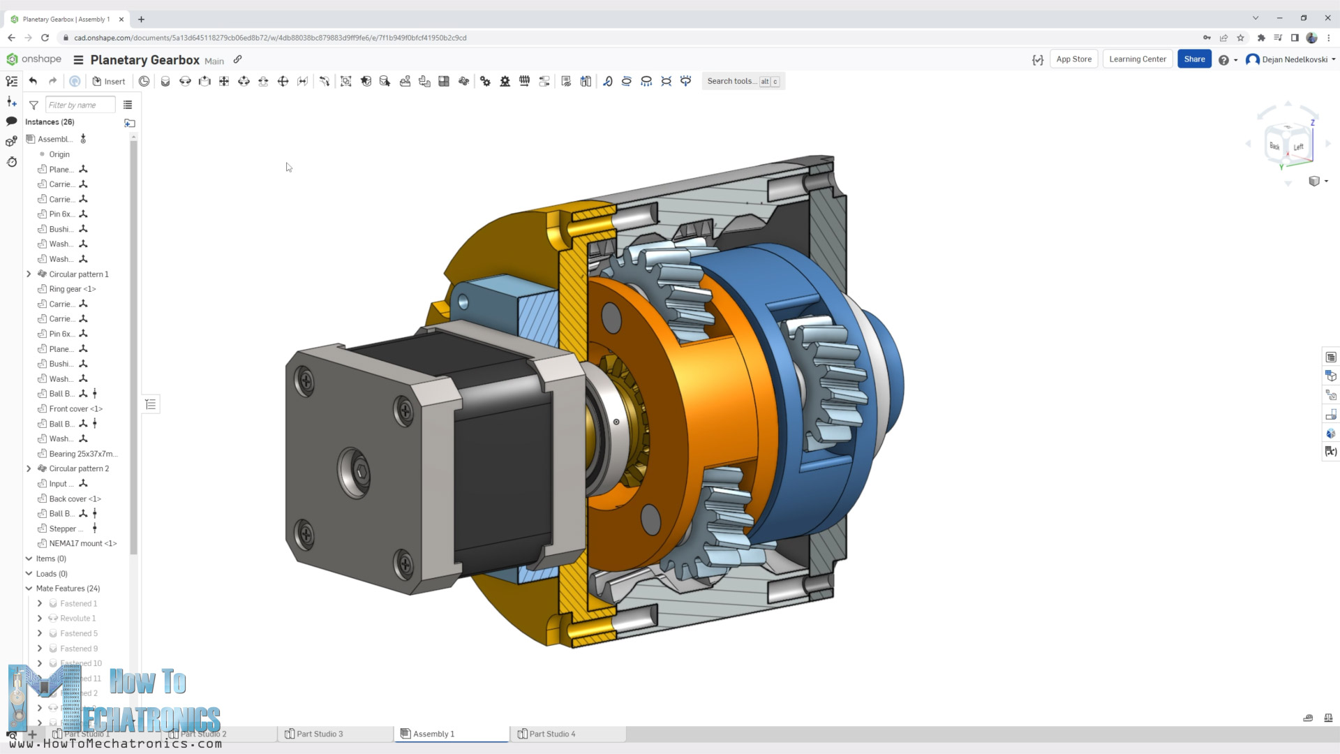
Nnow I would like to show you how I designed a 16:1 reduction ratio planetary gearbox for a NEMA17 stepper motor, which in terms of design is similar to a real gearbox.
At the end we will also do some torque and backlash tests to see how well it can perform being a 3D printed gearbox.
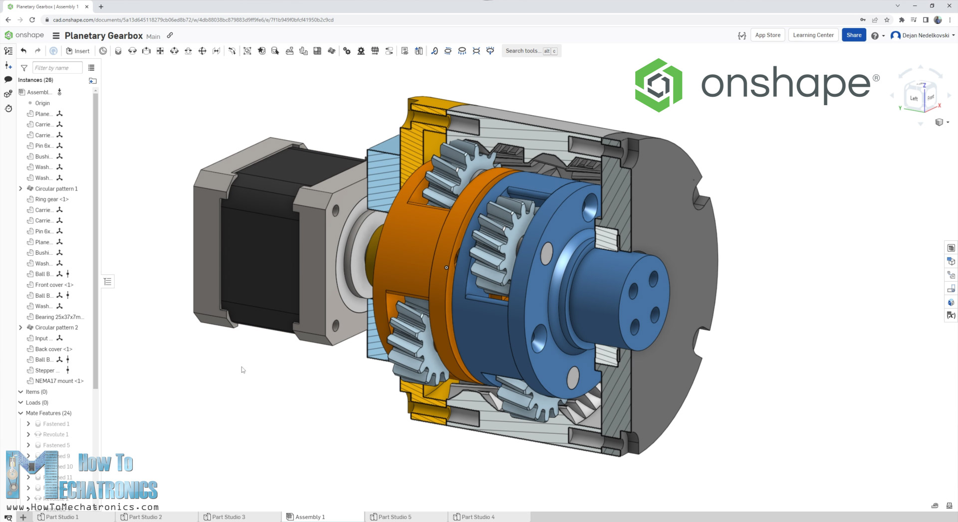
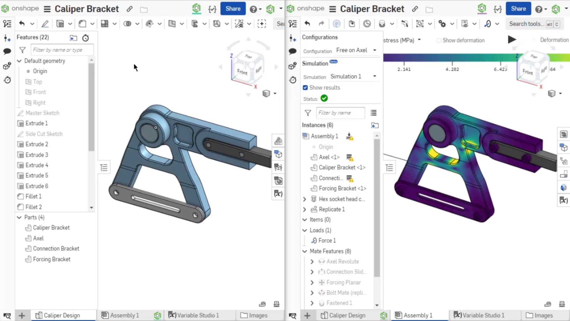
I designed this planetary gearbox using Onshape, which is the sponsor of this tutorial.
— Sponsored section —
Onshape is a cloud-native CAD + PDM system used by businesses, and there is also a free version for at home use.
Believe it or not, Onshape was actually created by the founders of SOLIDWORKS – with the rise of cloud computing the SOLIDWORKS founders realized that creating a CAD system from scratch in the cloud could create many new benefits that existing SOLIDWORKS users can’t experience.
One benefit for example is that in Onshape users are able to collaborate in real-time, similar to how google docs works, which allows engineering and design teams to be more productive than ever. And you also no longer need to be concerned with who has the most recent version of a file, or checking a file in and out of an expensive and hard to manage PDM system.
Onshape also works in a browser which means it works across all operating systems and devices, including iOS and android devices.
Whether your company uses Solidworks already and you are looking to modernize your engineering and design, or if you just want to try it out for at home use you can create a free Onshape account at https://Onshape.pro/HowToMechatronics.
Thanks Onshape for sponsoring education content like this.
— Back to topic —
Design
Now let me explain how I designed this planetary gearbox.
To begin with, the first input parameter for designing the gearbox was that I wanted to have a reduction ratio of around 15:1, and to be a whole number. In order to get such a ratio, the planetary gearbox had to be a two-stage gearbox. That means two planetary gear sets connected in series.
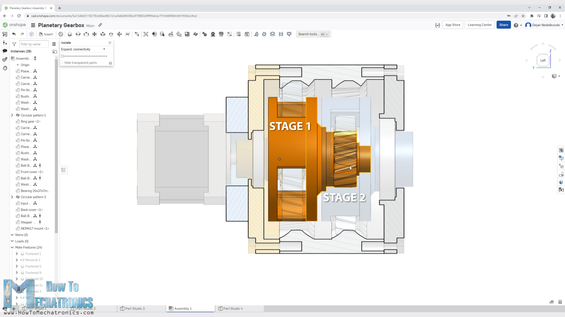
The output of the first planetary gear set is the input of the second planetary gear set. The final ratio of the gearbox is the product of the two gear sets ratios. That’s so because a single-stage planetary gearbox can typically provide ratios as low as 3:1 or as high as 10:1. In this way, with multiple stages, we can achieve very high reduction ratios with planetary gearboxes.
So, in order to get something around 15:1, we need two stages. In my case I chose two stages with 4:1 ratio, and when multiplied, they make 16:1 ratio. According to the formula in order to get 4:1 ratio, the ring gear teeth number should be 3 times the sun gear teeth.
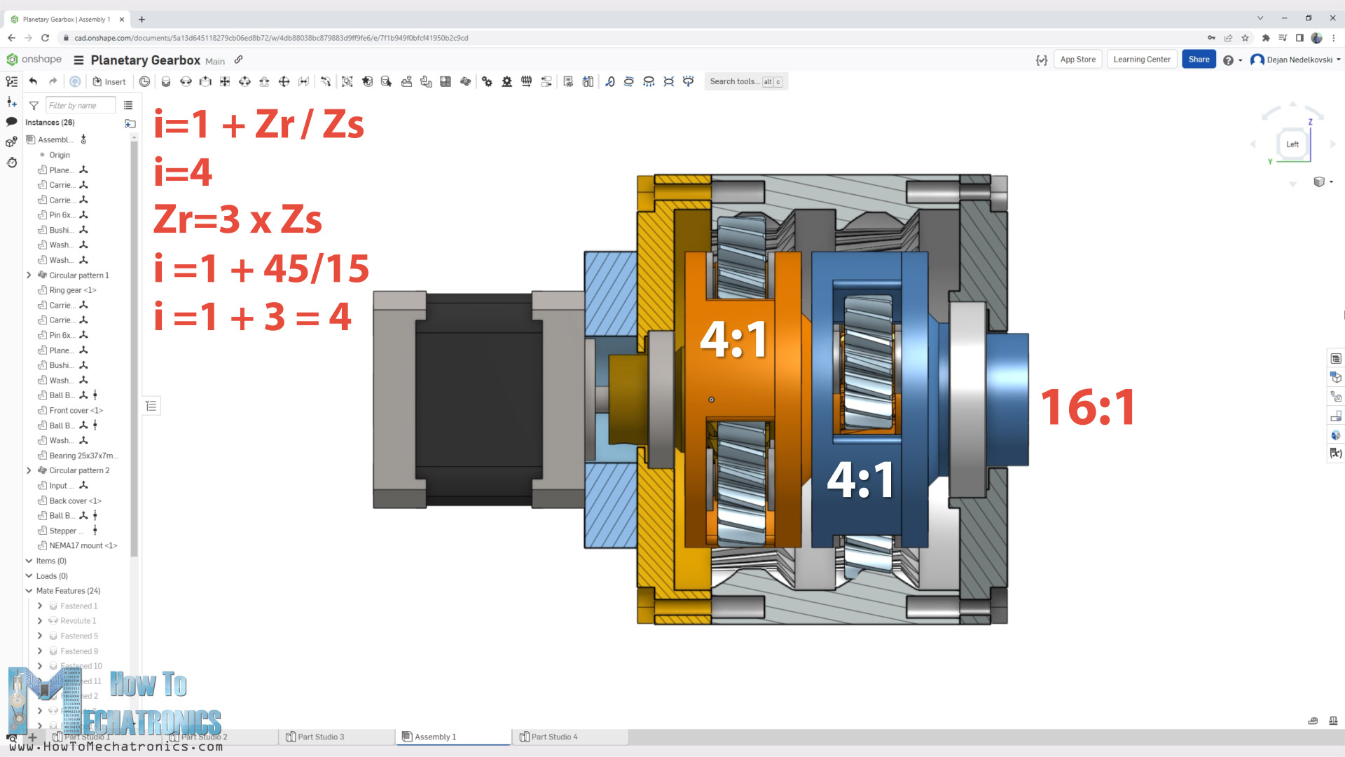
I chose 45 teeth for the ring gear, and 15 teeth for the sun gear. That’s 45/15 = 3 + 1 = 4, or 4:1 ratio. Though, there are some rules that we need to follow when choosing the number of teeth of the gears in order for the planetary gearbox to work.
Design Rules
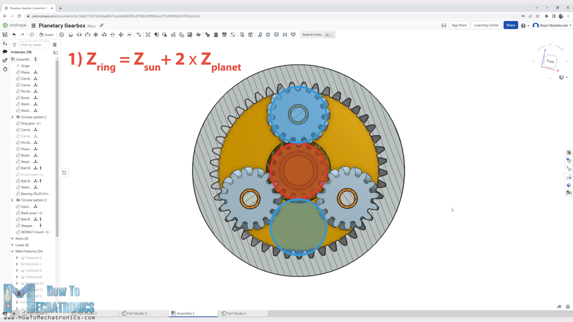
The first rule is that the ring gear teeth number must be equal to the sun gear + 2 * the planet gear teeth number. That basically means that the sun and two planet gears must fit inside the ring gear.
The second rule that we should follow is that the sun gear teeth plus the ring gear teeth, divided by the number of planet gears, should be equal to a whole number. In that way, the spacing between the planet gears will be equal, which is very important.
There are forces that occur between the sun and the planet gears that point toward the sun gear, so if planets are equally spaced, they will cancel out.
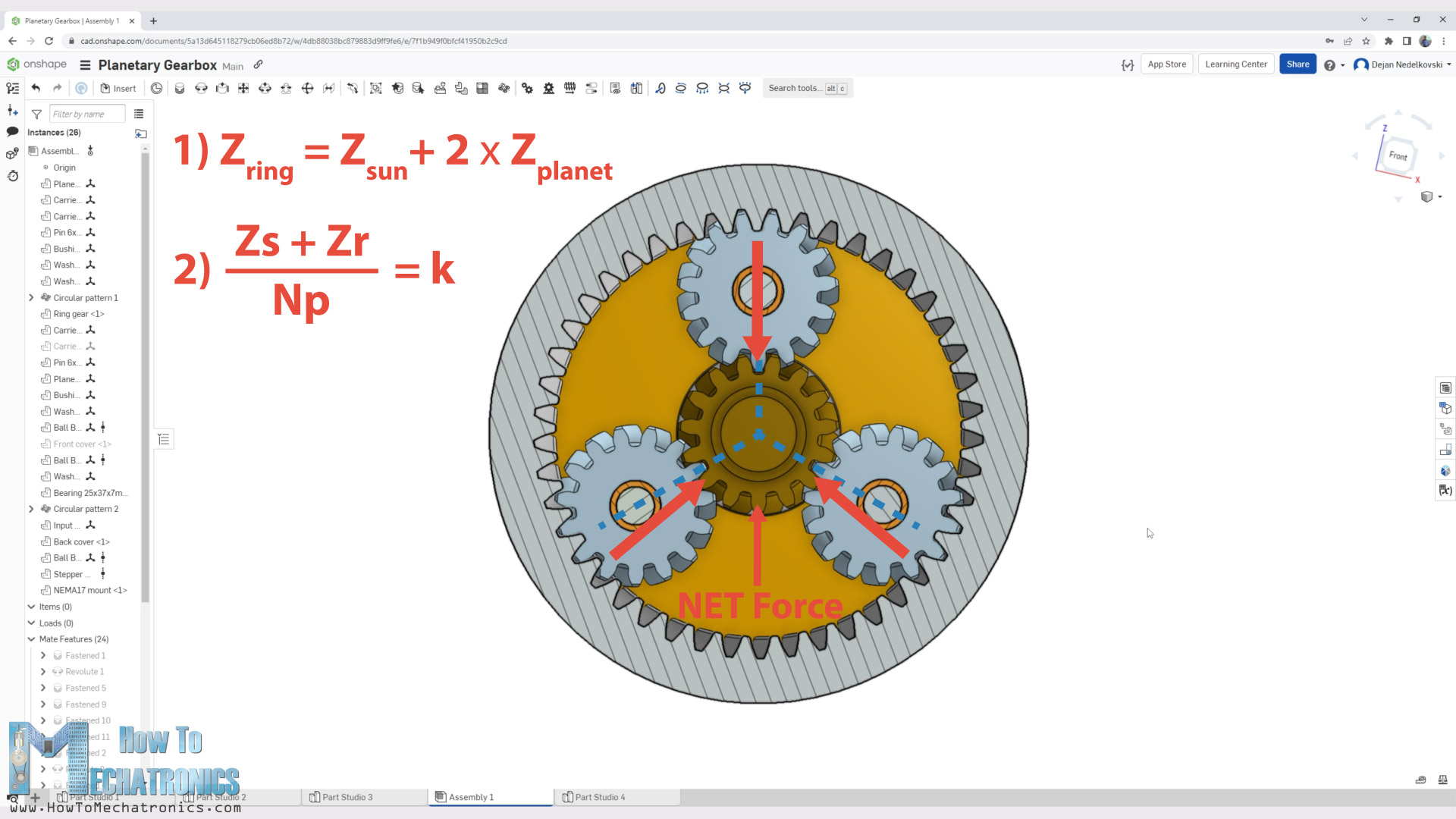
If not, a net force will occur that will tend to push the sun in a particular direction, which might cause the sun to wobble which will cause vibrations and the load sharing between the gears will be unbalanced.
Gears Teeth Number
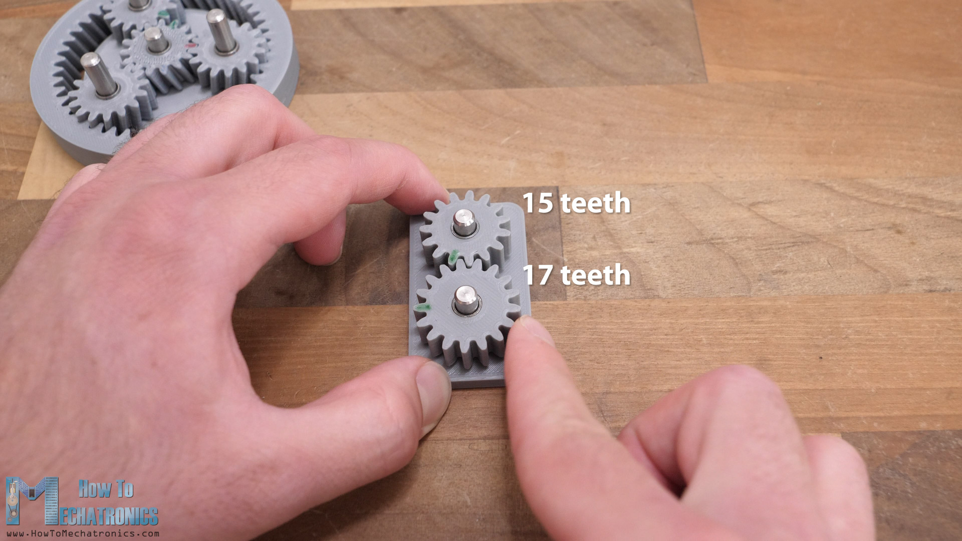
Still talking about the gear’s teeth number, having 15 teeth on the sun and 45 on the ring gear, will make the planet gears to have 15 teeth as well. That’s not a great scenario for the gears wear and durability.
In such a way, each tooth on the sun gear will mesh with the same tooth on the planet gear each rotation. That would cause uneven wear of the gears teeth. In order to avoid this, we should consider the number of teeth of the gears to be prime or co-prime numbers.
In such a way, a particular tooth on one of the gears, will mesh with every tooth of the other gear before meshing again with the starting tooth after a number of rotations.
However, I didn’t implement this suggestion for my gearbox, as it complicates a little bit the choosing of the gear’s teeth number. I will leave that for another video.
Gears Module
One more thing to talk about the design of the gearbox, before moving to 3D printing and assembling it, is the module of the gears. The module of a gear defines the size of the gear.
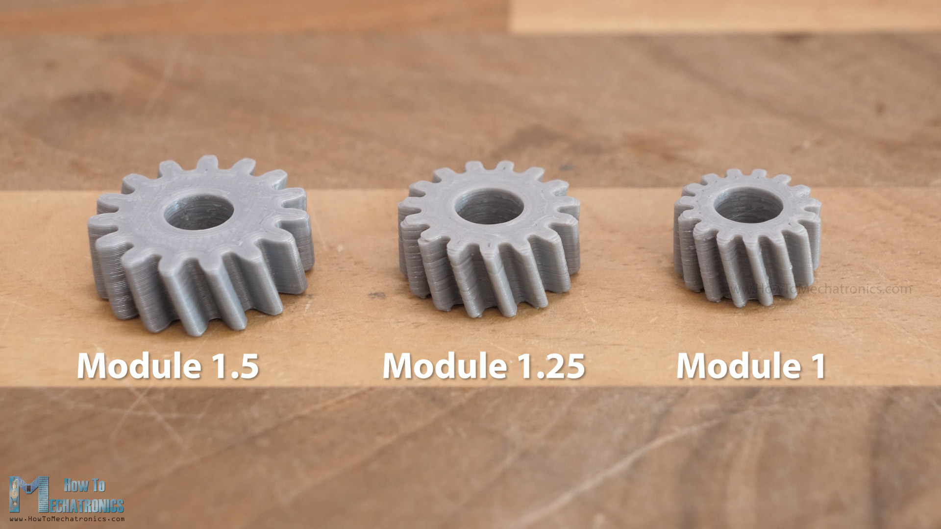
As I wanted the gearbox to be as small as possible, I had to choose a module as small as possible. I chose a module of 1.5, because if it’s lower than that, the 3D printer might not be able to print a good enough tooth profile, so we might lose efficiency. I mean, I haven’t done detailed testing for this matter, so I will also leave that for another video. For now, I’m going with a module of 1.5.
3D Modeling the Gearbox
So, once I had all of these parameters defined, I started designing the gearbox. With Onshape, it is quite easy to generate gears with the help of the FeatureScripts library. With the Spur Gear FeatureScript we can generate any type of gear within seconds. We just have to enter our parameters. The module will be 1.5, the number of teeth for the sun and the planet gears will be 15.
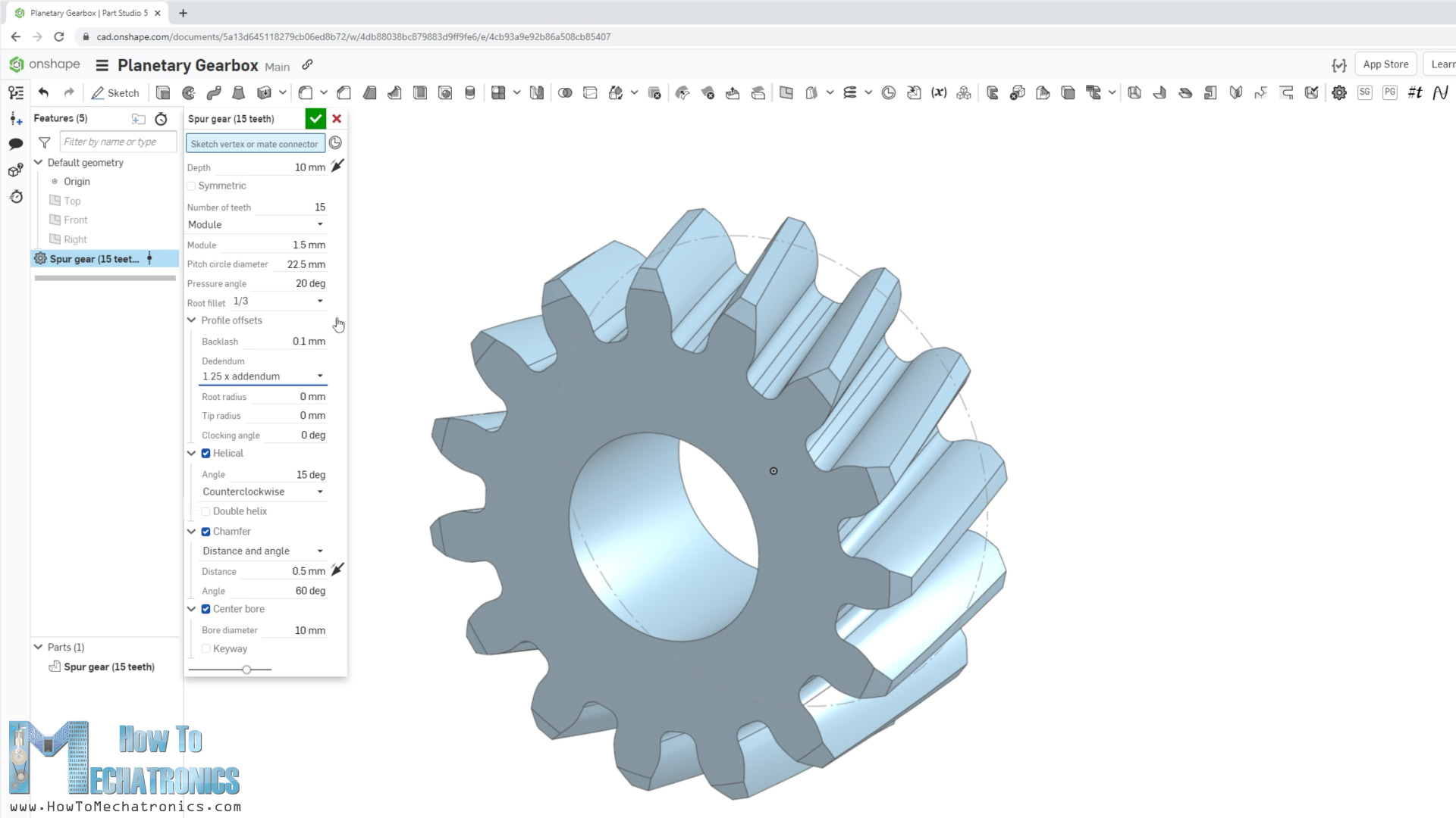
We can choose the gears to be helical and select the angle and the direction of the helix. Here we should note that in order for two helical gears to mesh, they need to have opposite direction of the helix, one clockwise, the other counterclockwise.
We can also choose the gear to be chamfered and have a central bore. Under the “Profile offsets” menu we can also enter a backlash value. We need to add some backlash because when 3D printing the parts usually come out a bit larger, so if we don’t add a backlash the gears won’t be able to mesh. I did some tests and a value of 0.1mm gave me a good result.
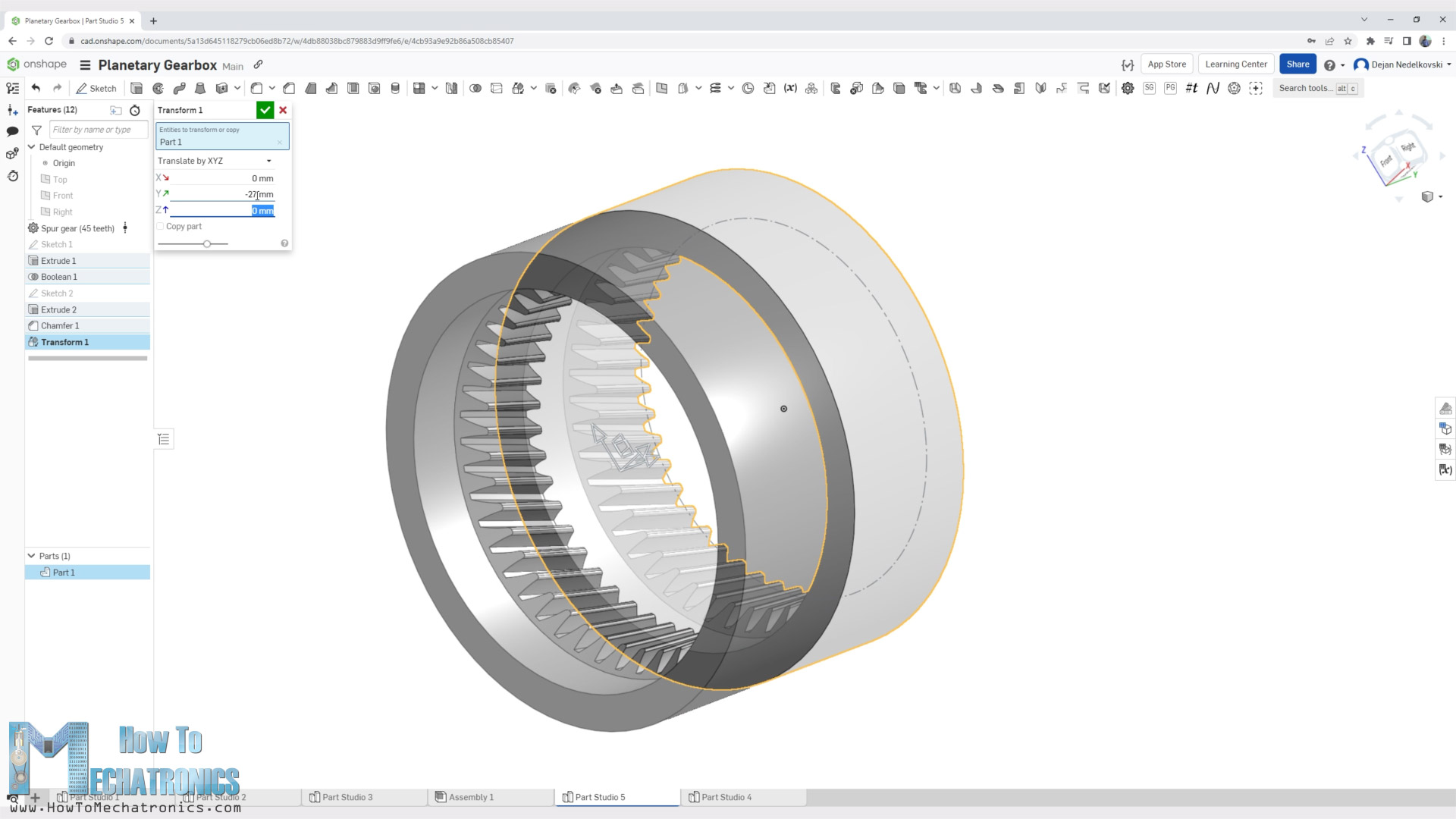
As for the ring gear which has internal teeth, first I generated a normal gear with 45 teeth.
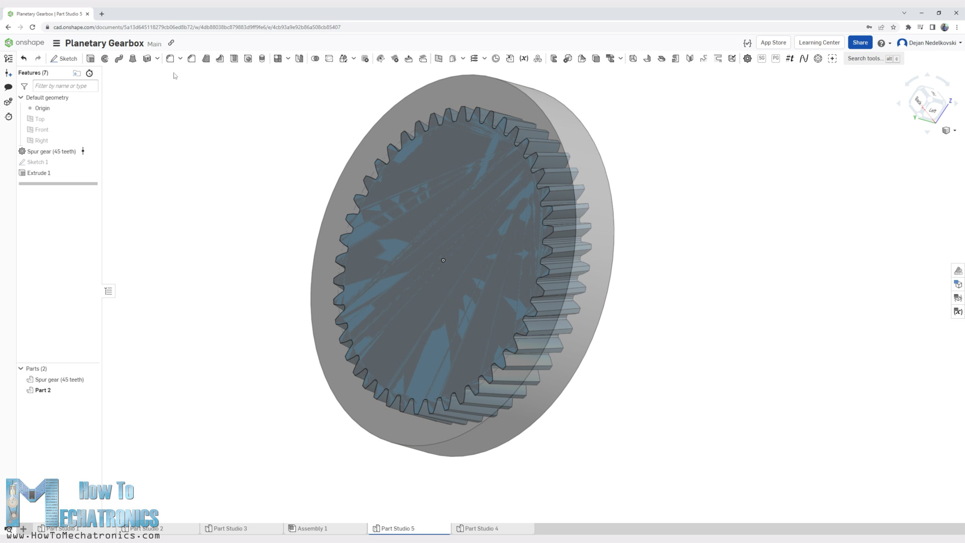
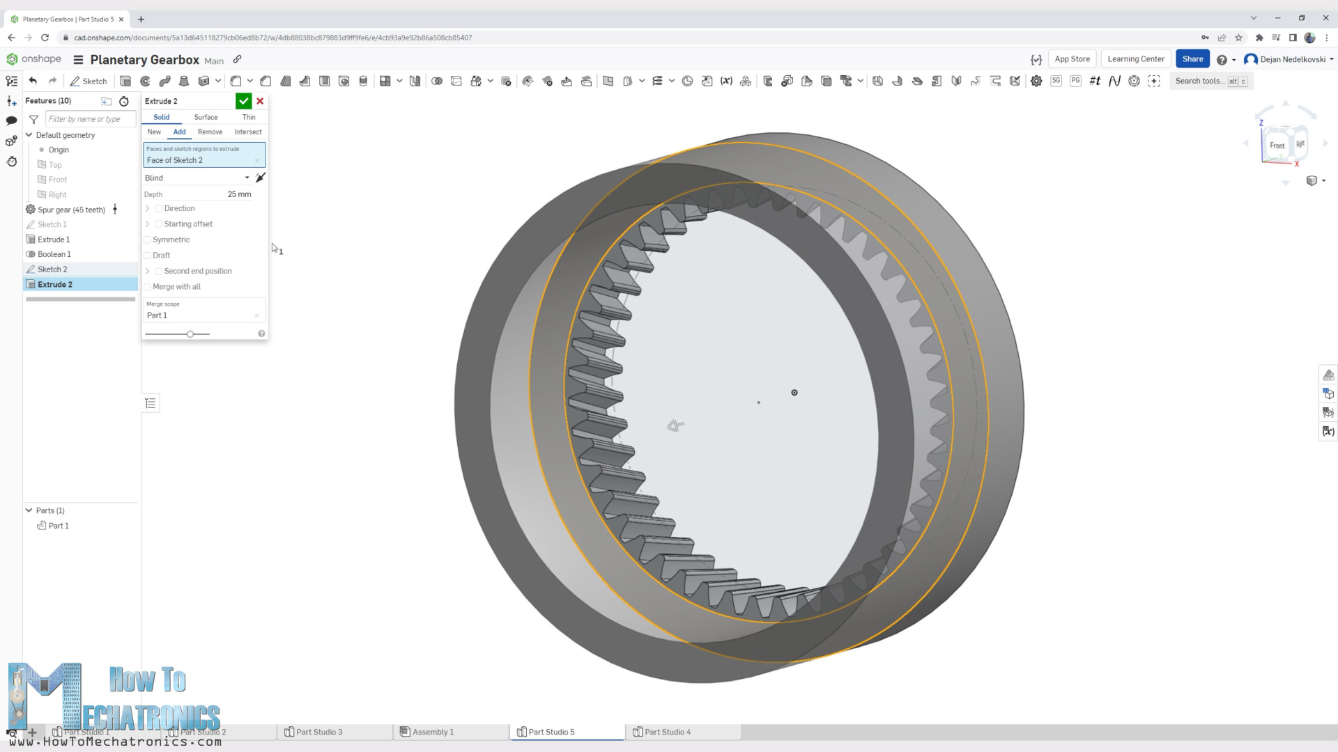
Then, I drew a circle with a desired diameter, extruded it within the gear itself, and then using the Boolean function, I subtracted the gear from the extrusion and so I was left with an internally toothed gear.
As we need the ring gear to be stationary, I continued to model this part as a housing of the gearbox.
I added chamfers to one side of the teeth to be easier to 3D printed them without support.
I made the second stage by making a copy of the part with the Transform function, and using the Boolean function made a union of the two parts and got a single part again.
I found this 3D modeling method, the Boolean function, that Onshape offers quite versatile.
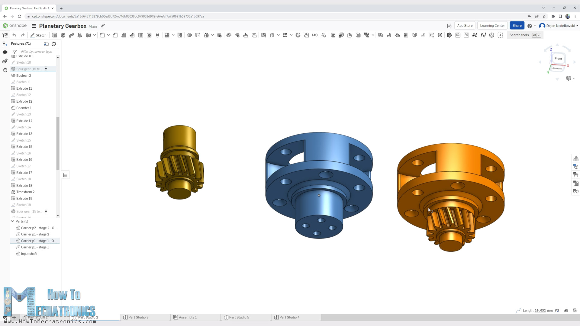
With the same method I designed the planet carries and the input shaft.
The design of the whole gearbox was actually based on the shafts and the bearings that I already had at home from my previous projects, the cycloidal drives. I had 6mm shafts with 22mm length. I used them for the planet gears in combination with some bushings.
As for the planet carrier, I designed it to support the shafts on both sides which made it a little bulky, but that will provide better performance.
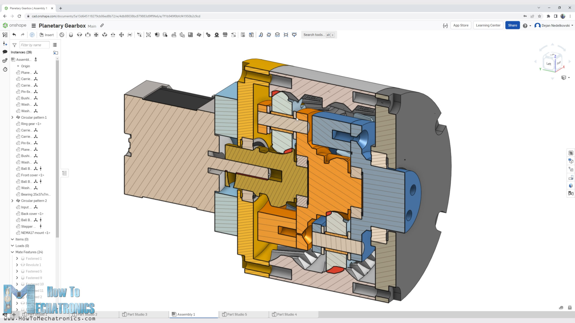
All right, so here’s a recap of the design and the working principle of the planetary gearbox. The motor drives the input shaft which is the sun gear of the first stage. That drives the planet gears, and the planet carrier outputs 4 times slower rotation. The planet carrier of the first stage is now the input or the sun gear of the second stage, where another 4 times speed reduction occurs.
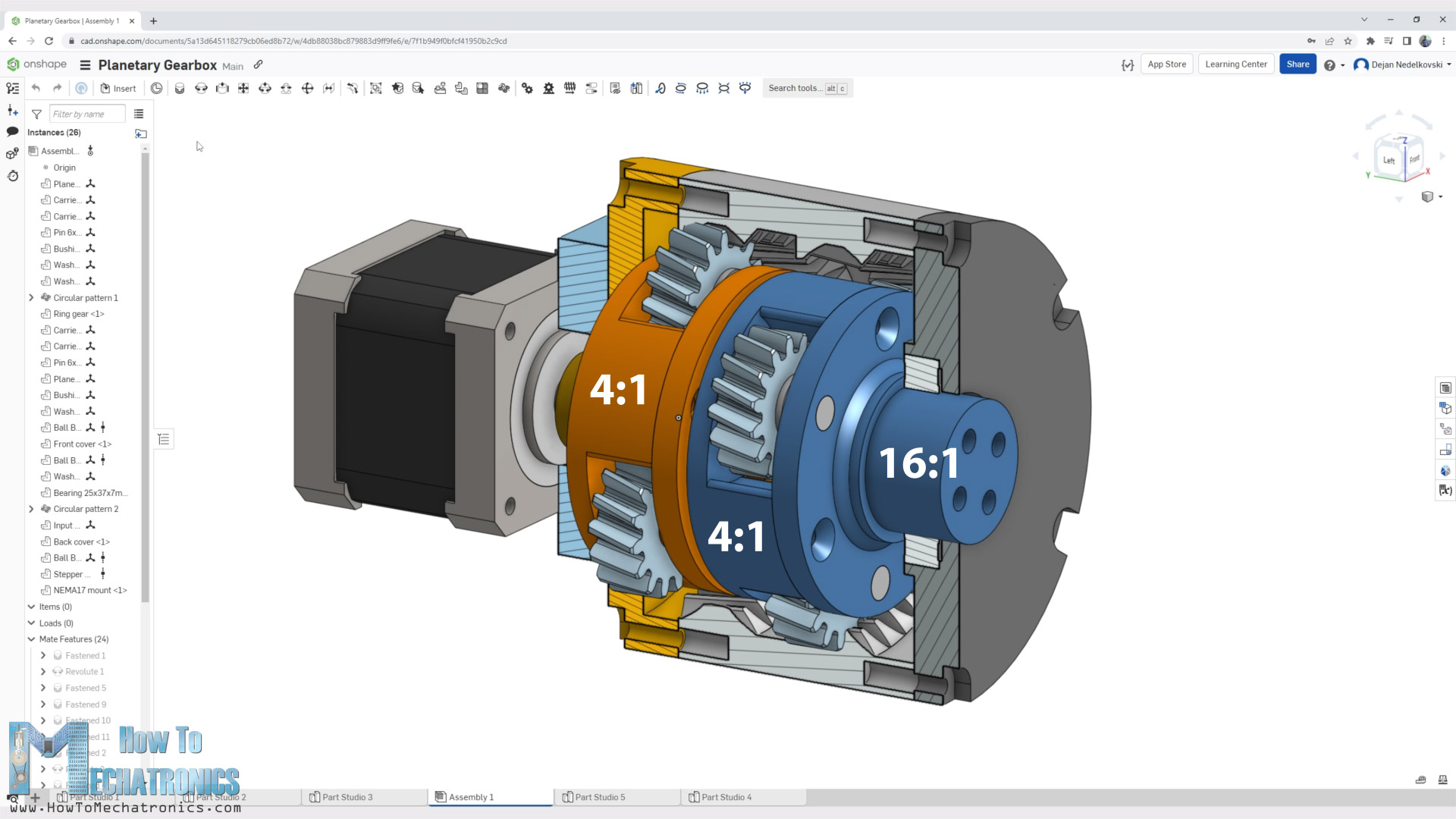
The planet carrier of the second stage is the final output shaft of the gearbox. The output speed of the gearbox is a product of the two stages reduction, or 4 times 4 equals 16 times lower output speed than in input of the motor. Proportionally, the torque of the gearbox is 16 times higher than the input of the motor.
3D Model and STL Files Download
Here you can download the 3D model of this planetary gearbox, as well as the STL files need for 3D printing the parts:
STEP file of the two-stage planetary gearbox:
Or you can view, copy the Onshape document so you can edit it or export the document directly on Onshape. (You need an Onshape account for that, you can create a free account for at home use)
STL files for 3D Printing:
3D Printing
When 3D printing, in order to get accurate dimensions of the parts, we need to have proper settings in our slicing software. The most important settings for getting dimensionally accurate prints are the Horizontal Expansion and Hole Horizontal Expansion settings.

If we leave these settings by default, the prints outer dimensions as well as the holes are usually smaller than the original model. I set the Horizontal Expansion to 0.02mm and the Hole Horizontal Expansion to 0.04mm. Of course, you should do some test prints to see what values will give you the best results on your 3D Printer.
Assembling the Planetary Gearbox
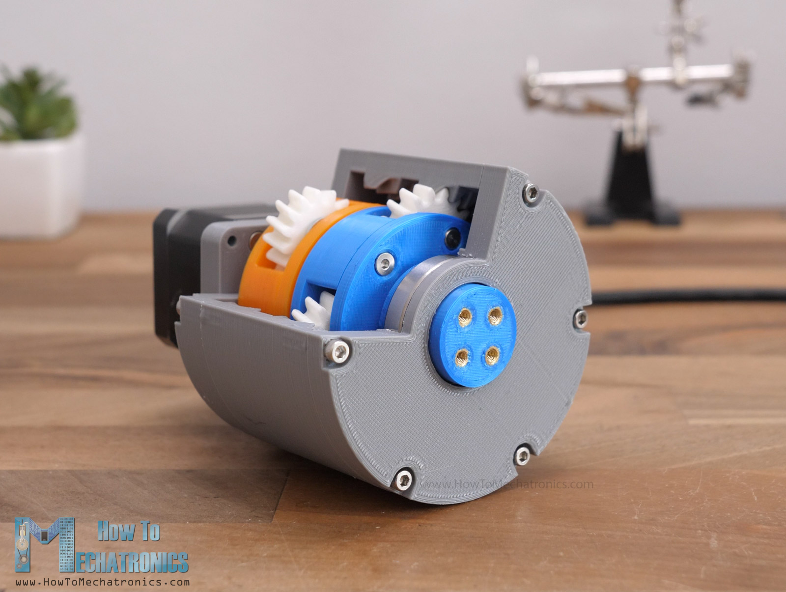
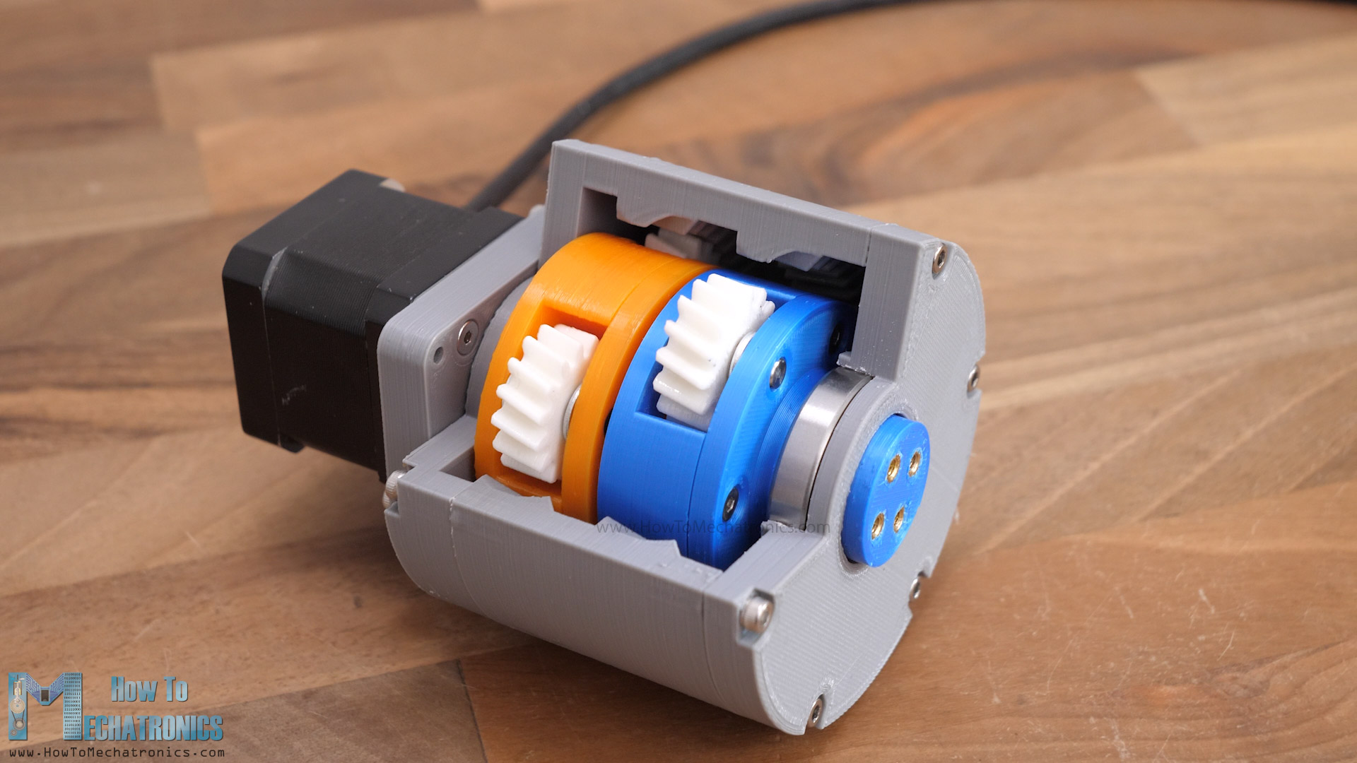
Ok, so here are all 3D printed parts ready and now I can show you how I assembled the gearbox. For better visualization I printed each of the parts in a different color.
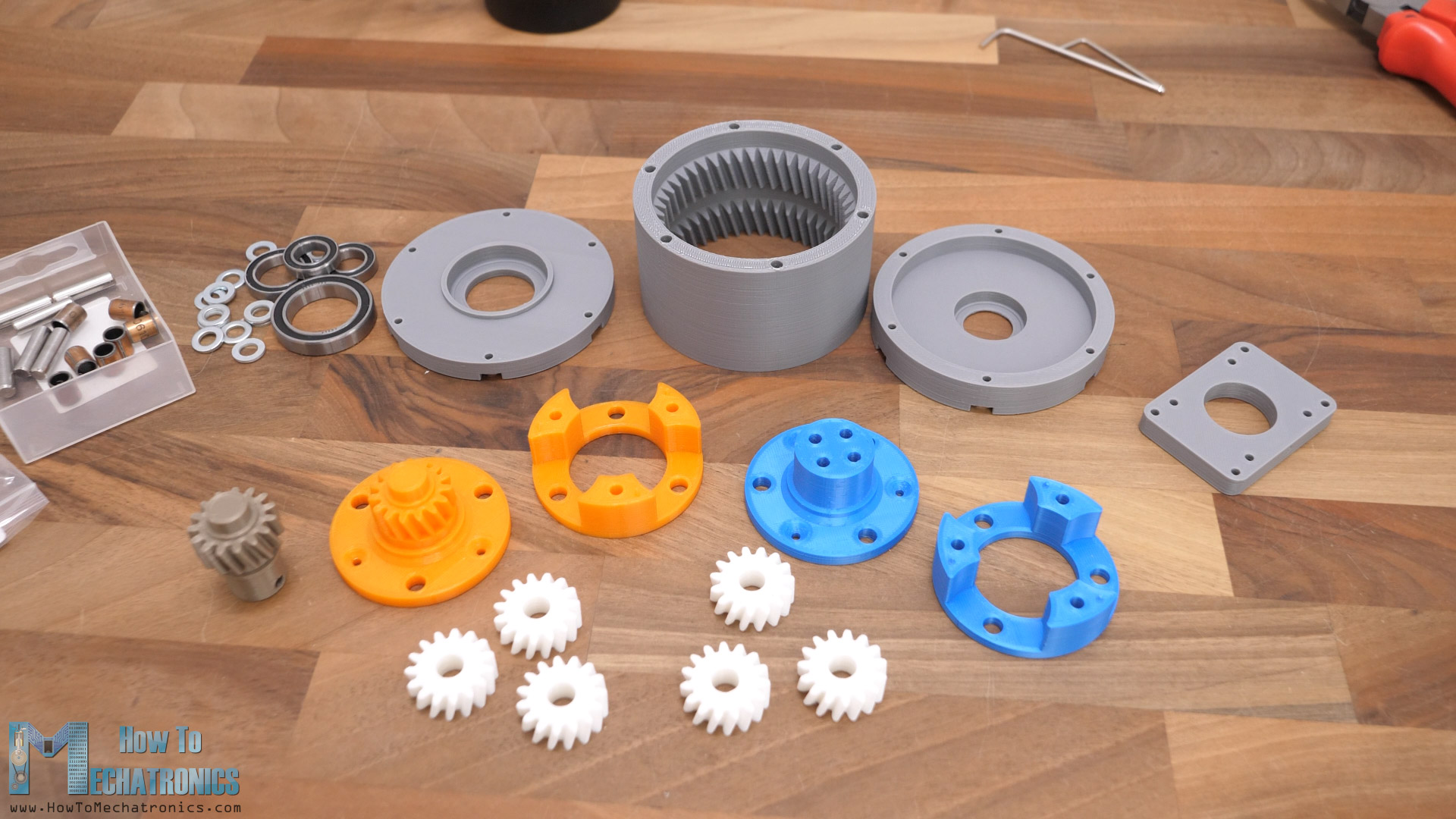
The input shaft is gold, the first stage carrier is orange, the planet gears are white, the second stage carrier and output blue, and the ring gears or the housing is gray. Everything is 3D printed with PLA filament.
Parts List
Here’s a list of all components needed for assembling the planetary gearbox:
- 6mm Steel Cylinder Rod ………………….…. Amazon / AliExpress
L=22mm x6 pcs - 8mm Bushings …………………………………. Amazon / AliExpress
L=10mm x6 pcs - Ball Bearing 25x37x7mm 6805 – x2 …… Amazon / AliExpress
- Ball Bearing 17x26x5mm 6803 x2 ……… Amazon / AliExpress
- Ball bearing 12x21x5mm 6802 – x2 ….. Amazon / AliExpress
- Threaded inserts M3x5mm ………….……. Amazon / AliExpress
- M3 bolts and nuts …………………………….. Amazon / AliExpress
Disclosure: These are affiliate links. As an Amazon Associate I earn from qualifying purchases.
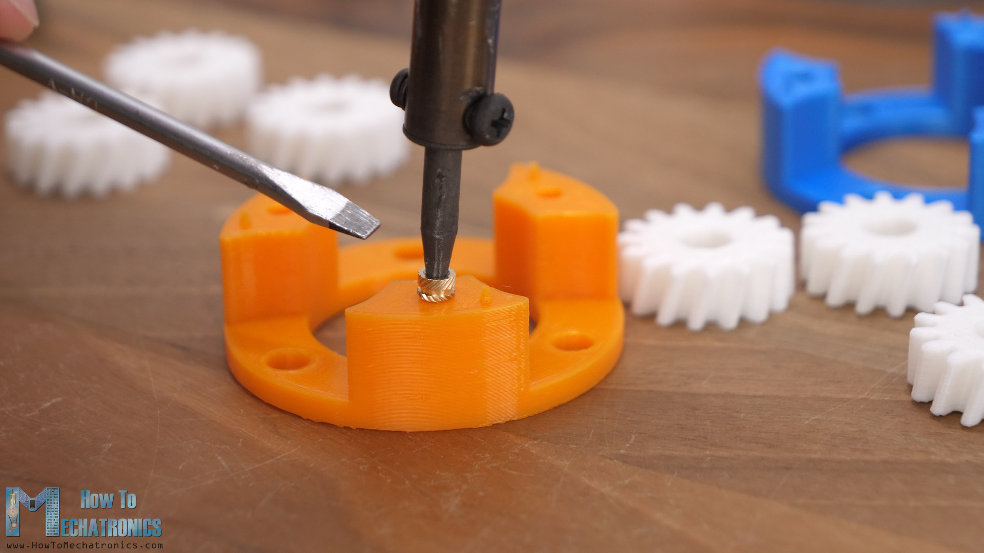
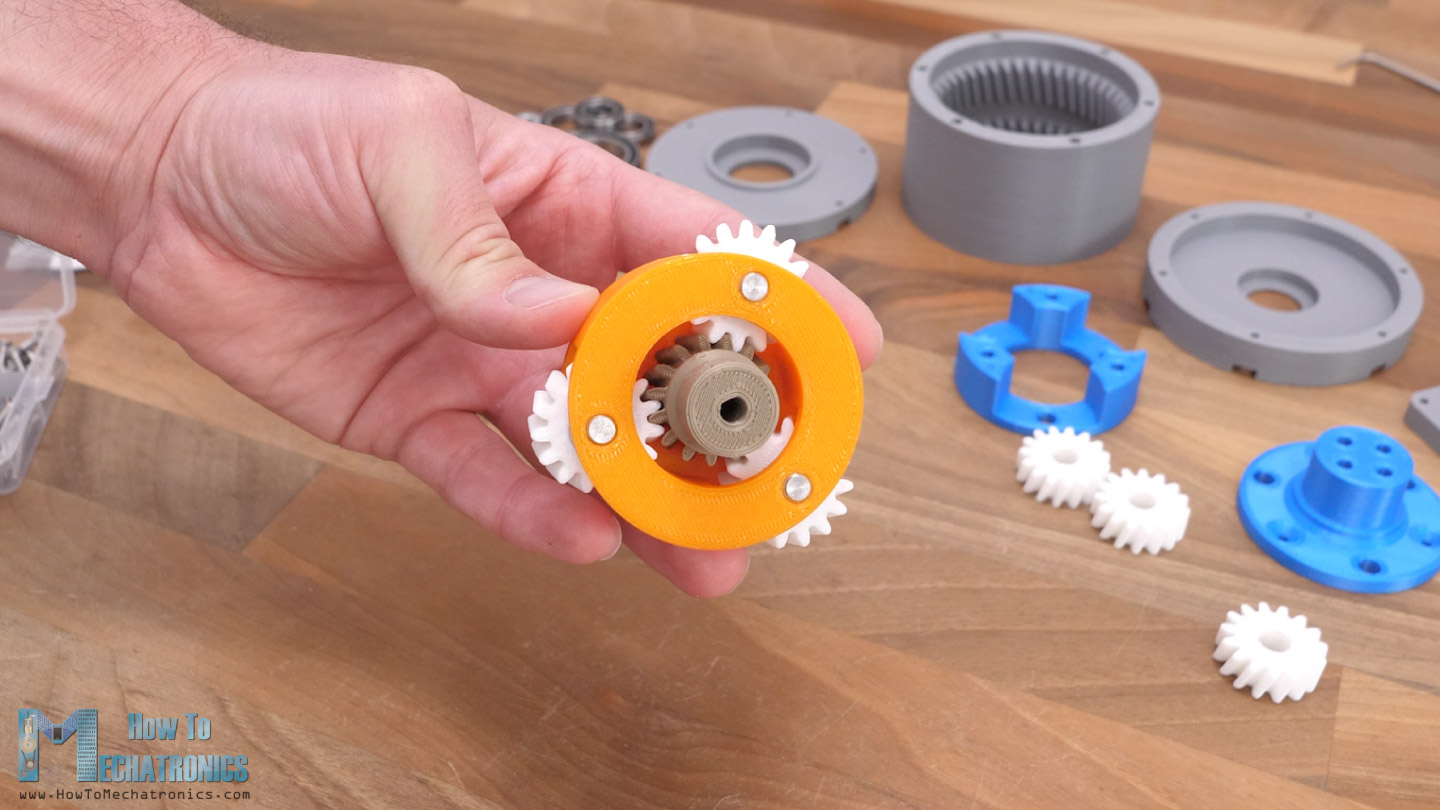
The planet carries are composed of two sections that need to be connected together with some M3 bolts, so first we need to insert some M3 threaded inserts into the prints.
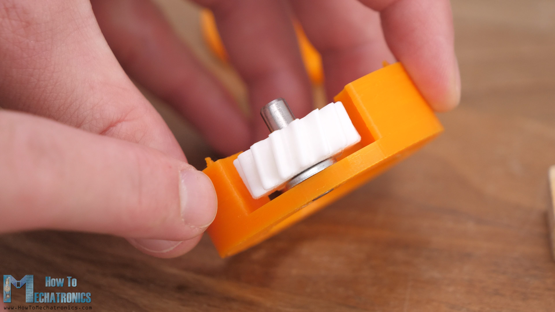
Then we can install the 6mm shaft in place for the planet gears.
On the planet gear I installed suitable bushing with 8mm outer diameter and 10mm length. The planet gears are 9mm thick, and the extra 1mm of the bushing should be distributed on both sides of the gear. Then we will insert M6 washers on both sides of the gear and so the bushing will be in contact with the metal washer which makes better contact instead of touching the plastic gear.
Ideal here instead of bushings we should use other types of bearing which can accept the axal forces that occur due to the helical tooth profile of the gears. But just like I already mentioned, I designed the gearbox based on the components that I had at home from my previous projects.
Once the three planet gears are installed, we can simply insert the other section of the carrier in place and secure them together with the help of some M3 bolts.
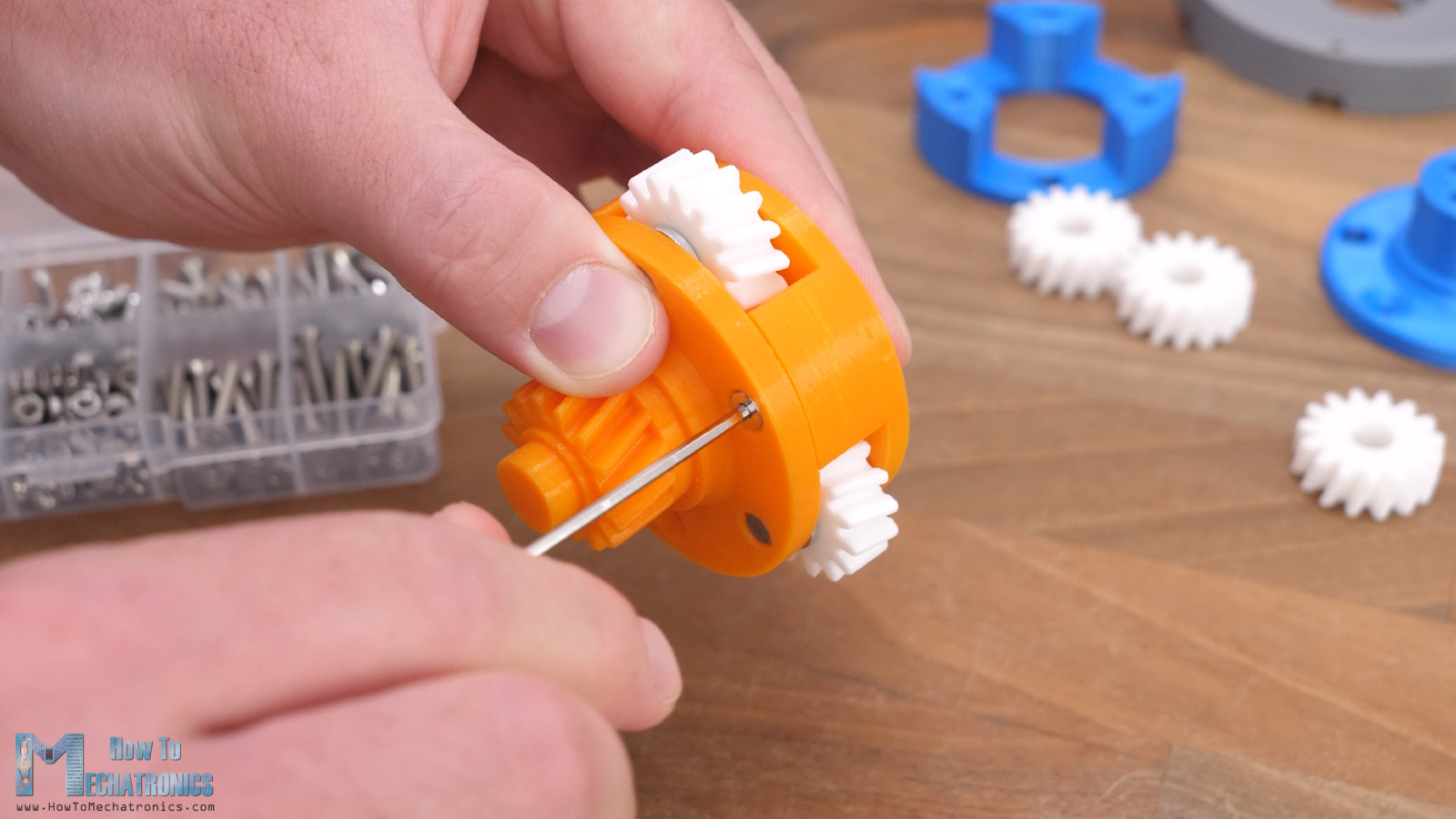
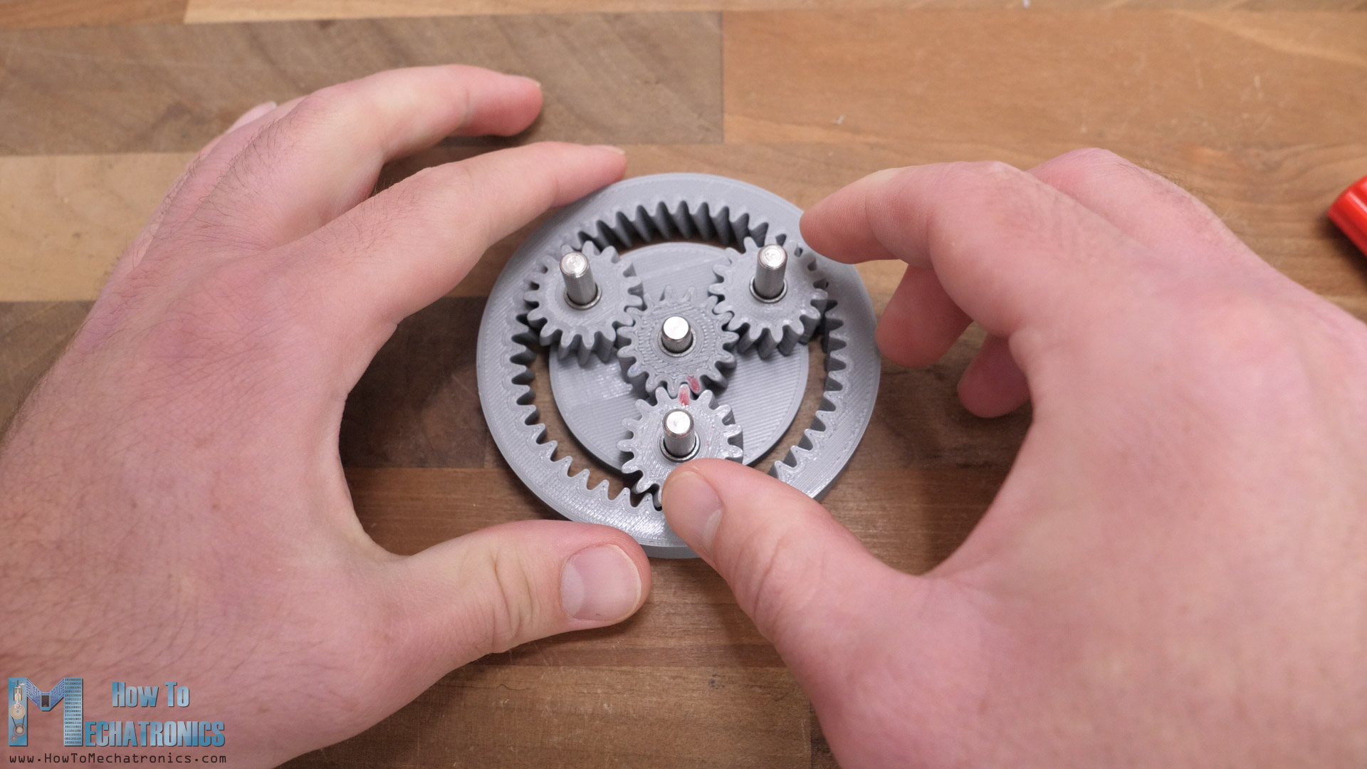
Here’s how the first stage looks like when we insert the input shaft or the sun gear and insert everything into the housing or the ring gear. The carrier rotates 4 times slower than the input shaft.
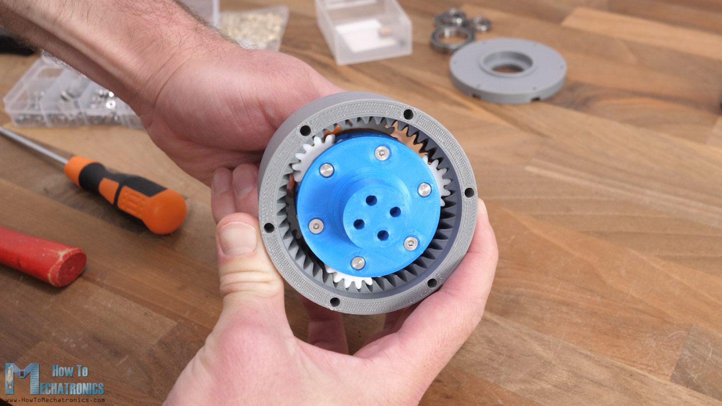
The second planetary gear set is assembled the same way, and once insert it in place into the housing, we can see how the whole planetary gearing system works. The output shaft rotates 16 times slower than the input.
Before we continue with the assembly, we need take out the carries to insert the bearings inside them for supporting the sun gear input shafts. Though, I had to disassemble the carrier because the bearing couldn’t pass in-between the planet gears.
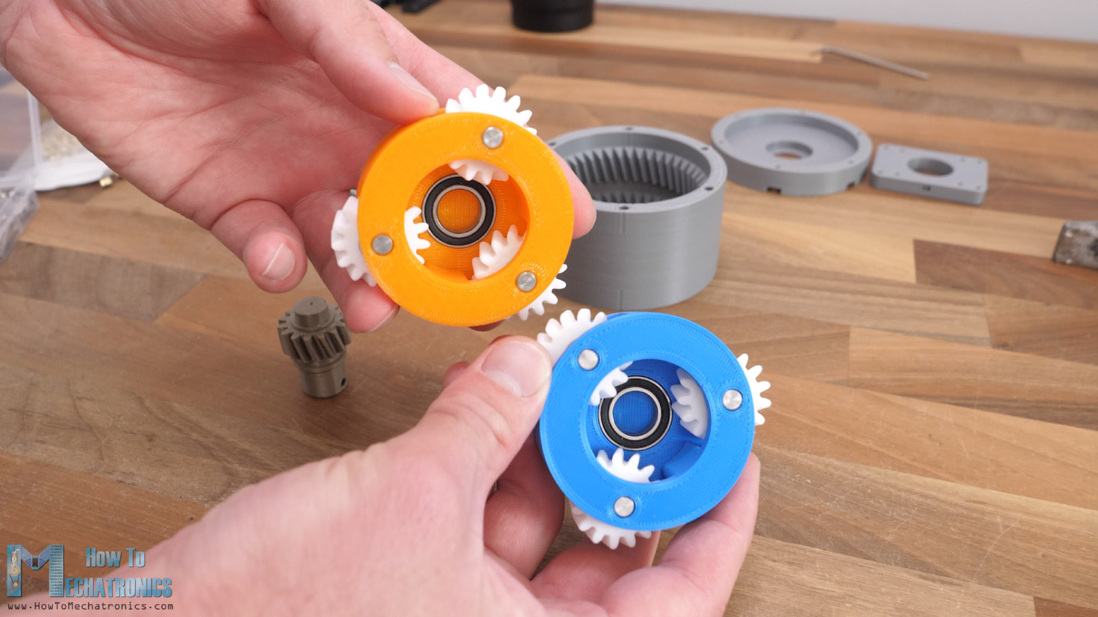
Here are the two bearings in place in the carries, so we can move on with the assembly. Before inserting them in the housing, first I added some threaded inserts on the housing which will be used for securing the back and front cover of the gearbox.
For smoother operation I added some lubrication to the gearing.
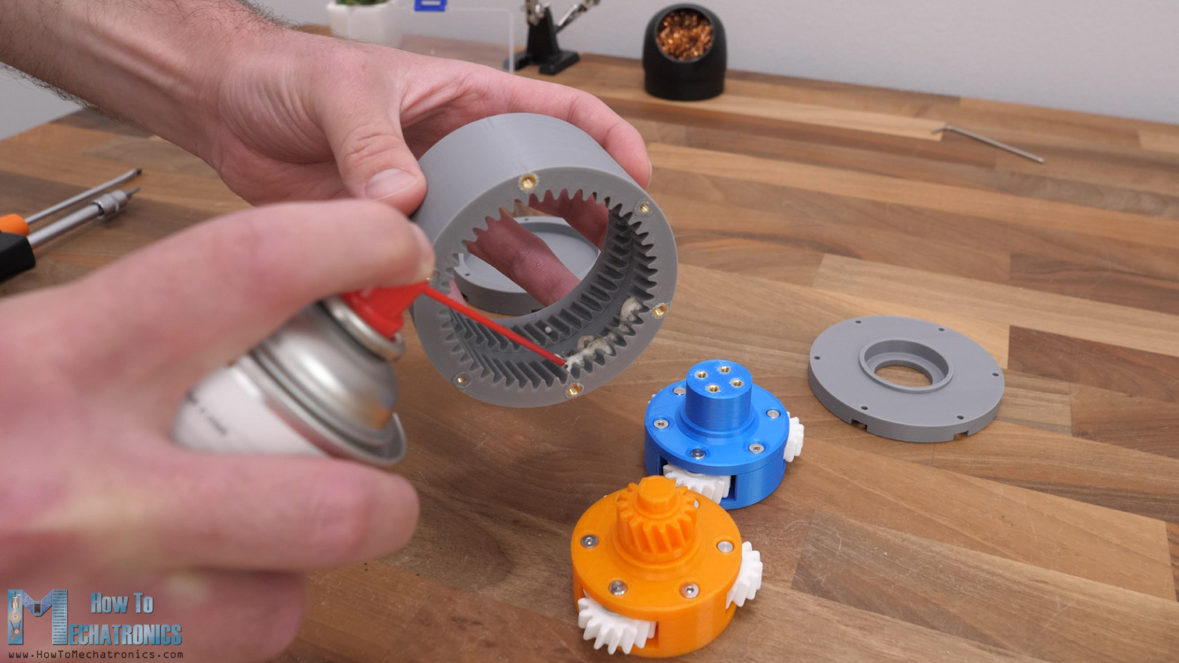
The gears meshed snugly in place, with very little resistance when rotating the input shaft and at the same time it feels like there is almost no backlash, but we will see the actual backlash a bit later in the video when we will test the gearbox.
Next, we can install the bearing on the output shaft, and put the front cover in place.
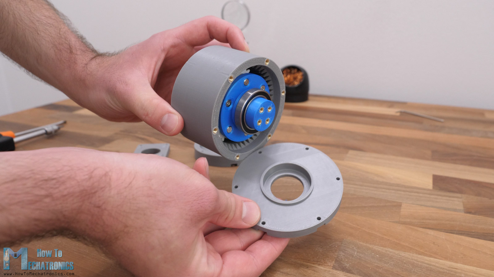
We secure the cover with some M3 bolts. With the same method, we insert the bearing for the input shaft on the back cover and secure it in place with some M3 bolts again.
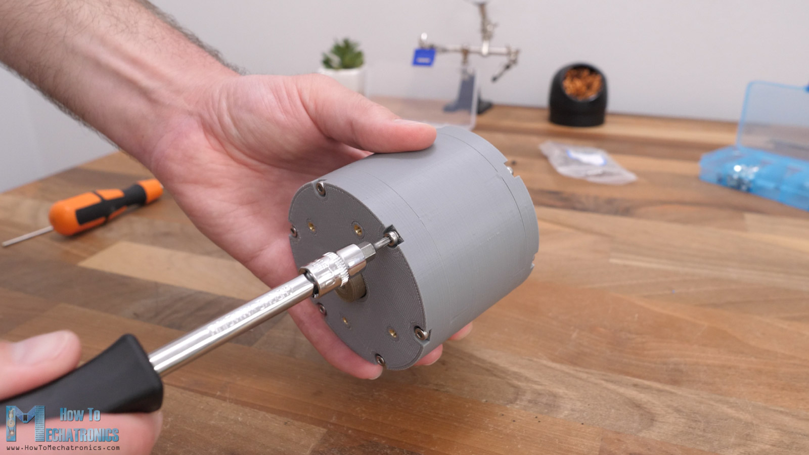
And that’s it, our planetary gearbox is completed. I really like how clean the design came out.
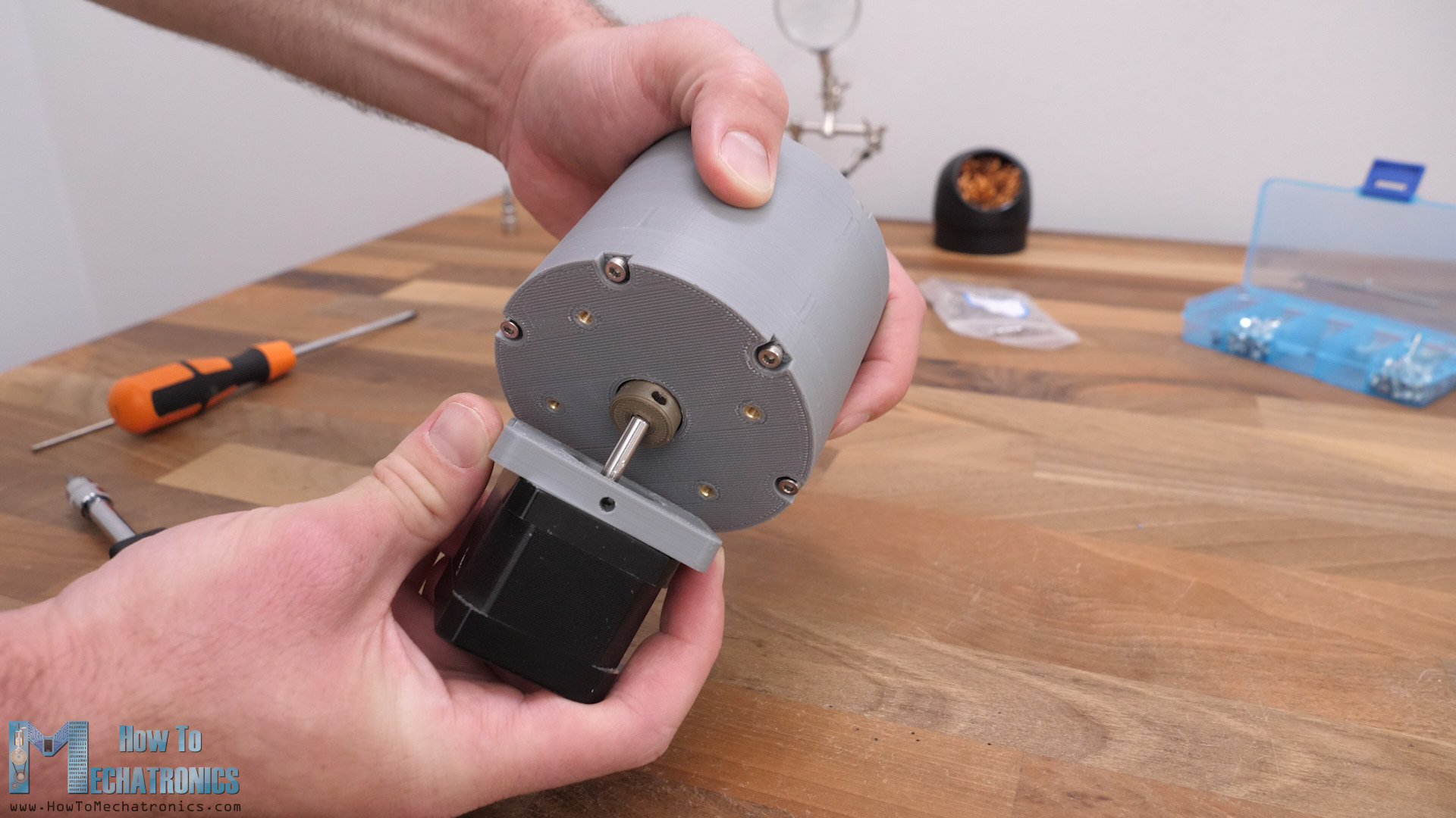
Mounting a NEMA 17 stepper
What’s left now is to attach a motor to it, a NEMA 17 stepper in this case. In order to secure the stepper motor to the gearbox we need an additional mounting plate which we first need to secure it to the stepper motor.
Before inserting the motor in place, we can insert a grub screw into the input shaft through which we can tighten the motor shaft to the gearbox input shaft.
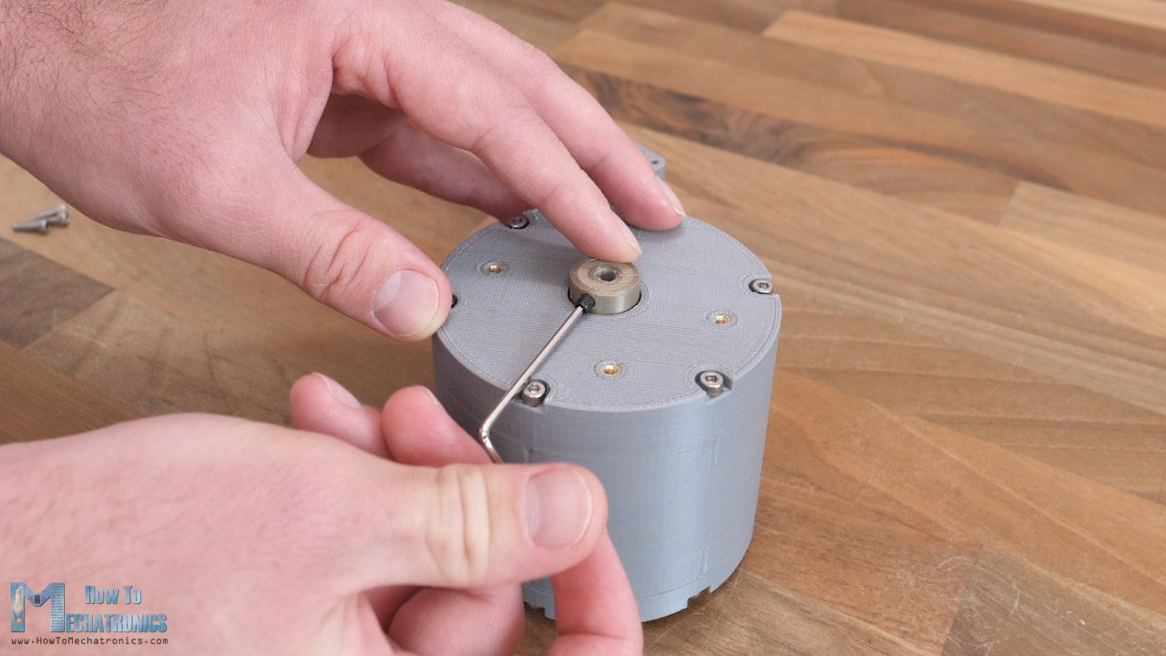
Then we can simply slide in the stepper motor shaft into the gearbox input shaft and secure the mounting plate to the gearbox with four M3 bolts.
On the mounting plate there is a hole thorough which we can tighten motor shaft to the input shaft with the grub screw. And that’s it, our 3D printed planetary gearbox is completed.
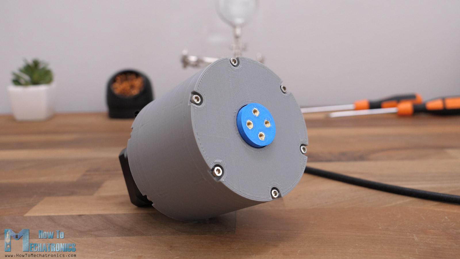
The output shaft rotates 16 times slower than the input of the motor and it’s quite smooth.
Testing
Ok so now let’s do some tests to see how well the gearbox will perform.
Backlash
First let’s check the accuracy of the gearbox. I was actually surprised how good the repeatability was. At a distance of 10cm there wasn’t even 1/100th of a millimeter play.
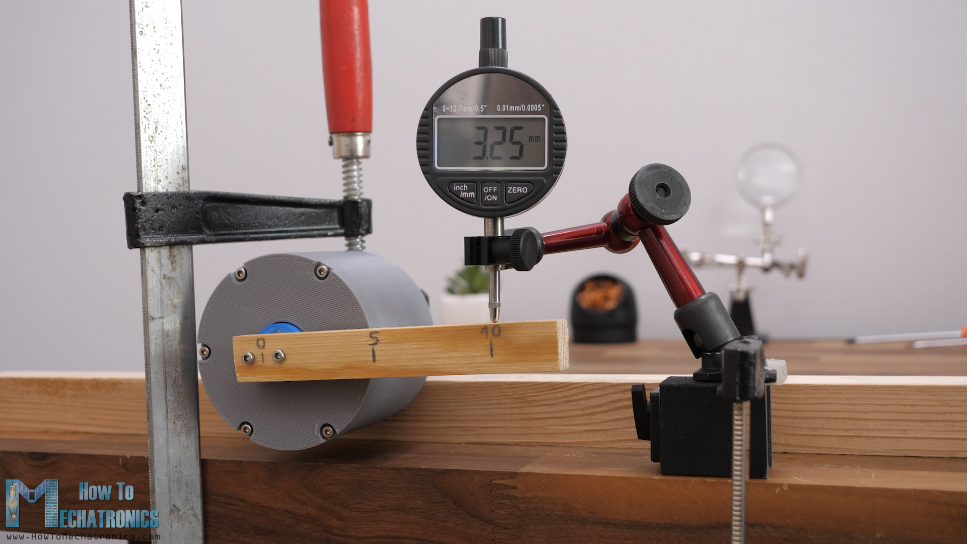
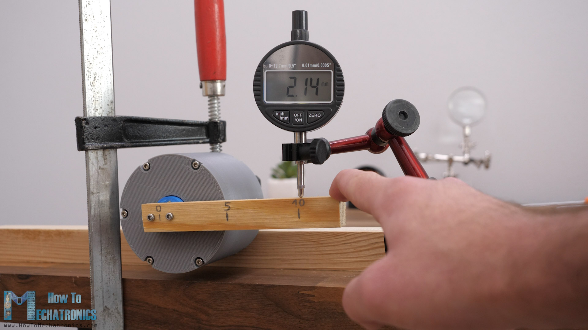
Of course, if we apply some force to the output, we can notice some displacement. It was around 1.2mm displacement in both directions.
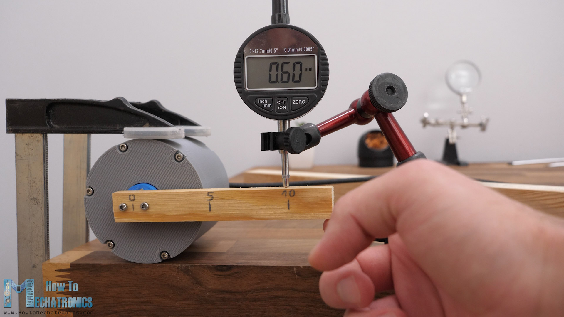
Actually, even less than that, when I clamped the gearbox itself, rather than the stepper motor, around 0.6mm play in each direction.
That’s a very good result, but to express the backlash in its typical unit, arcminutes, we need to do the following. We should measure the displacement in both directions, while applying a load of around 1-2% of the nominal torque capability of the gearbox.
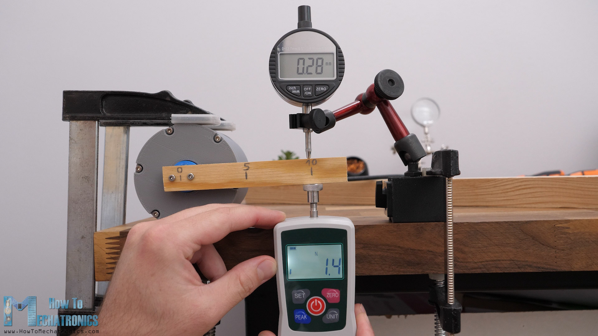
When testing the torque of the gearbox, I got a maximum reading of around 20N at a distance of 10cm, so I guess for testing the backlash we should apply a load of around 0.5N, but let’s make it 1.5N at a distance of 10cm. With this load I got a displacement of around 0.3mm in one direction and 0.2mm in the other direction.
Calculating Backlash in Arcminutes
To express these measurements in backlash unit, arcminutes, first we can calculate the angle of displacement, alpha.
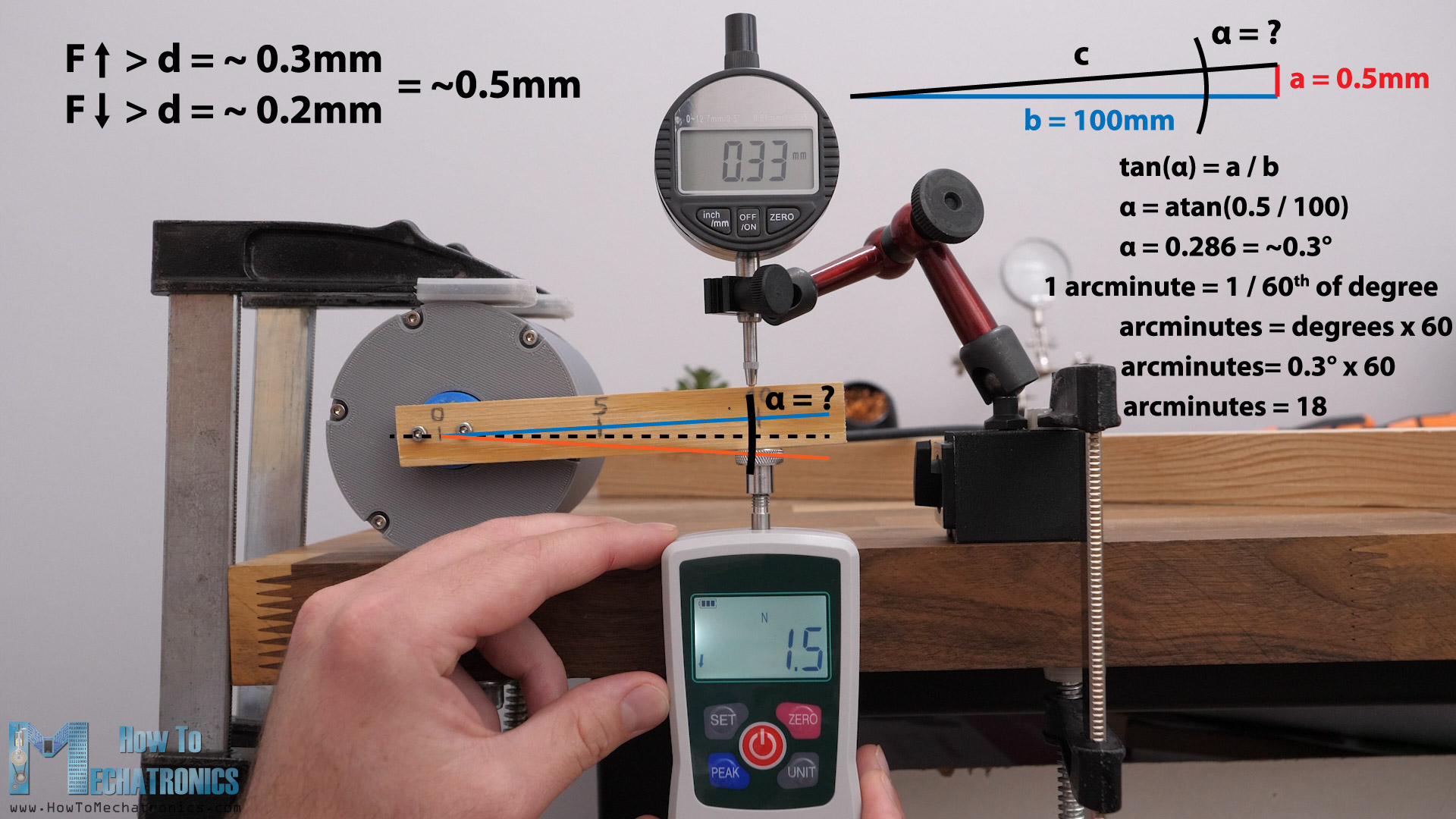
We do that with the help of some simple trigonometry, and the angle comes out to be around 0.3 degrees. One arcminute is 1/60th of a degree. So, the backlash of this 3D printed planetary gearbox is around 18 arcminutes.
That’s a really impressive result, of course, if these measurements are correct. Please let me know in the comments if you know whether that’s the right way to take the measurements and calculate the backlash.
Torque
As for the torque, as I mentioned, I got a reading of around 20N at a distance of 10cm, or that’s a torque of around 200Nm.
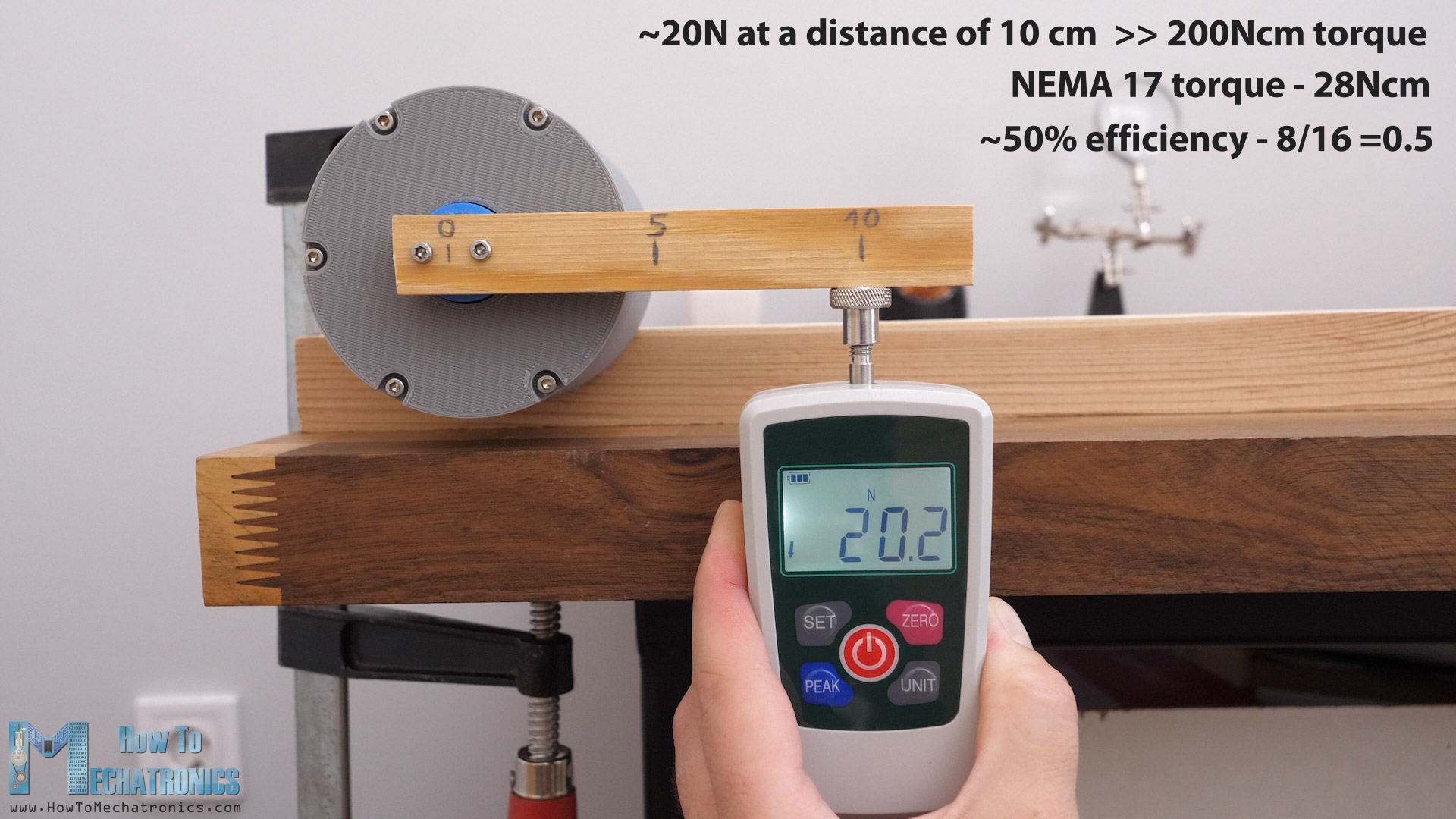
Compared to the torque this NEMA17 stepper has without the gearbox, which is around 28Nm, that’s a torque increase of just around 7 or 8 times. That’s a very low efficiency of the gearbox of just around 50%. The reduction ratio of the gearbox is 16:1, and in ideal conditions we should get 16 times torque increase, but we got half of that.
I conducted the tests using the following measuring gear:
- Force meter ………………………. Amazon / AliExpress
- Digital dial indicator ………… Amazon / AliExpress
Disclosure: These are affiliate links. As an Amazon Associate I earn from qualifying purchases.
Conclusion
I guess there’s lot of friction going on in the gearbox and that’s why we lose efficiency. But on the other hand, because of that friction, or tight fit of the gears, we are getting so got results in terms of backlash.
We can increase the efficiency of the gearbox if we lower the friction or print the gears teeth profile with added backlash value when generating them, but then we would increase the backlash. These two things are related to each other. Of course, there are other things that contribute to the low efficiency, and that’s the bushings that I used for this gearbox, instead of ball bearings.
Overall, I’m very pleased with the results that this 3D printed planetary gearbox provided. Now I’m looking forward to make a comparison video of a 3D printed planetary gearbox like this, versus a 3D printed cycloidal drive and a harmonic drive, which also showed quite good results in my previous videos. Of course, I will implement all the experience I’ve gained making gearboxes from my previous videos and try to make them as good as possible and test them more extensively.
I hope you enjoyed this tutorial and learned something new. Feel free to ask any question in the comments section below.