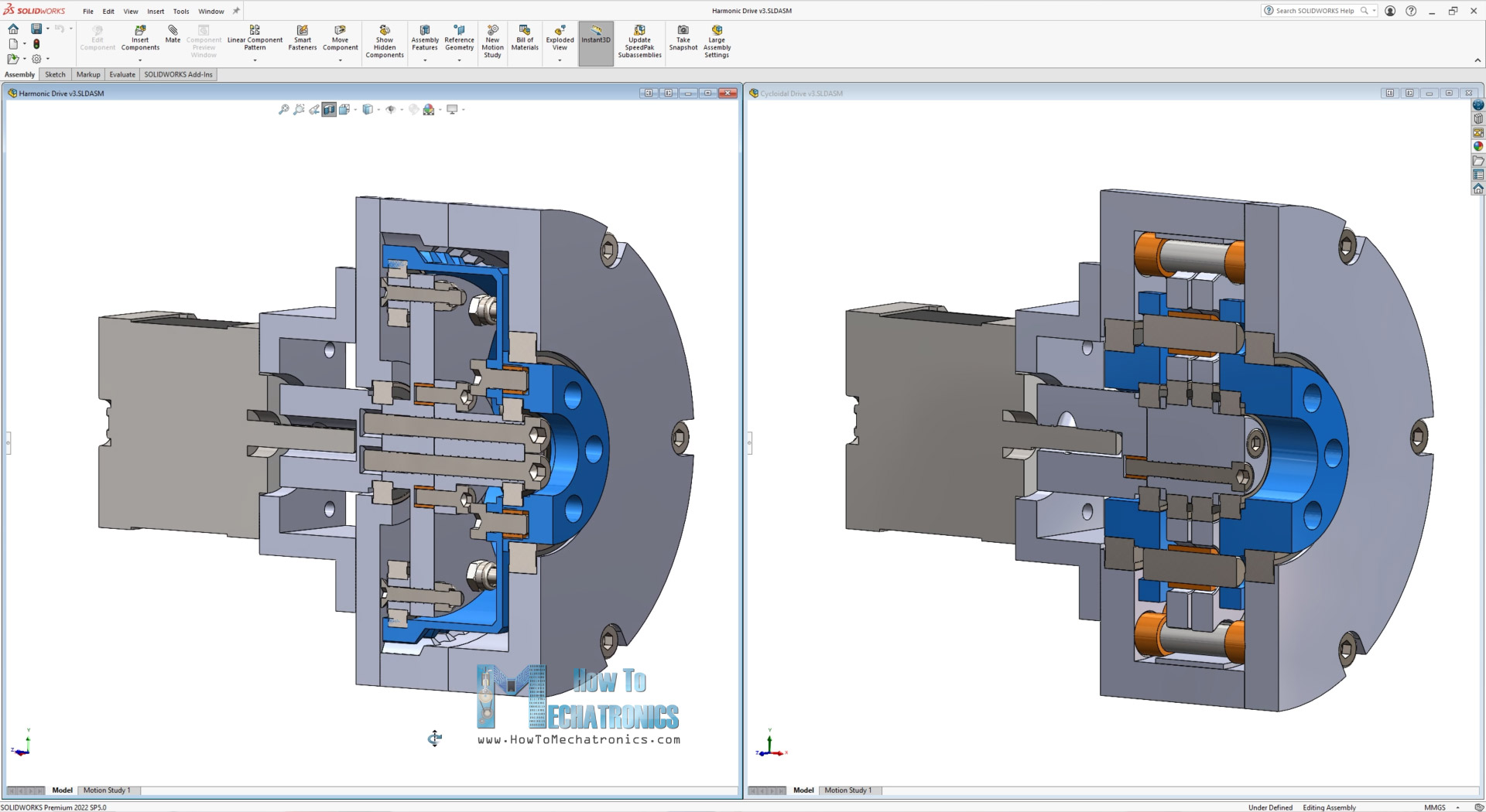
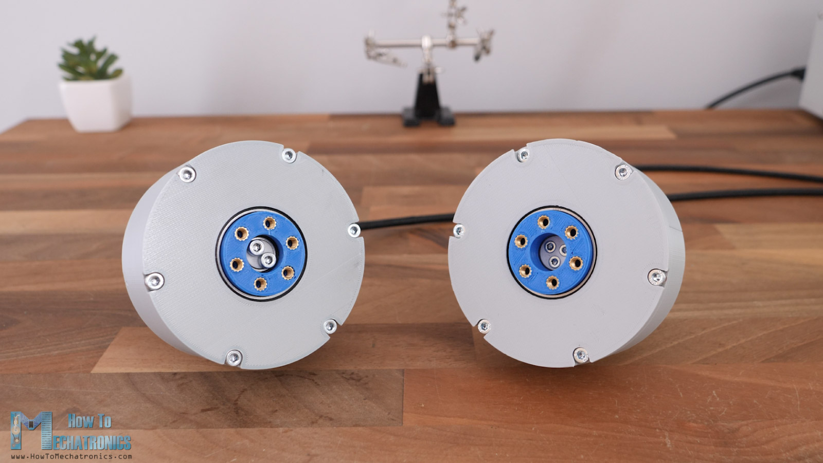
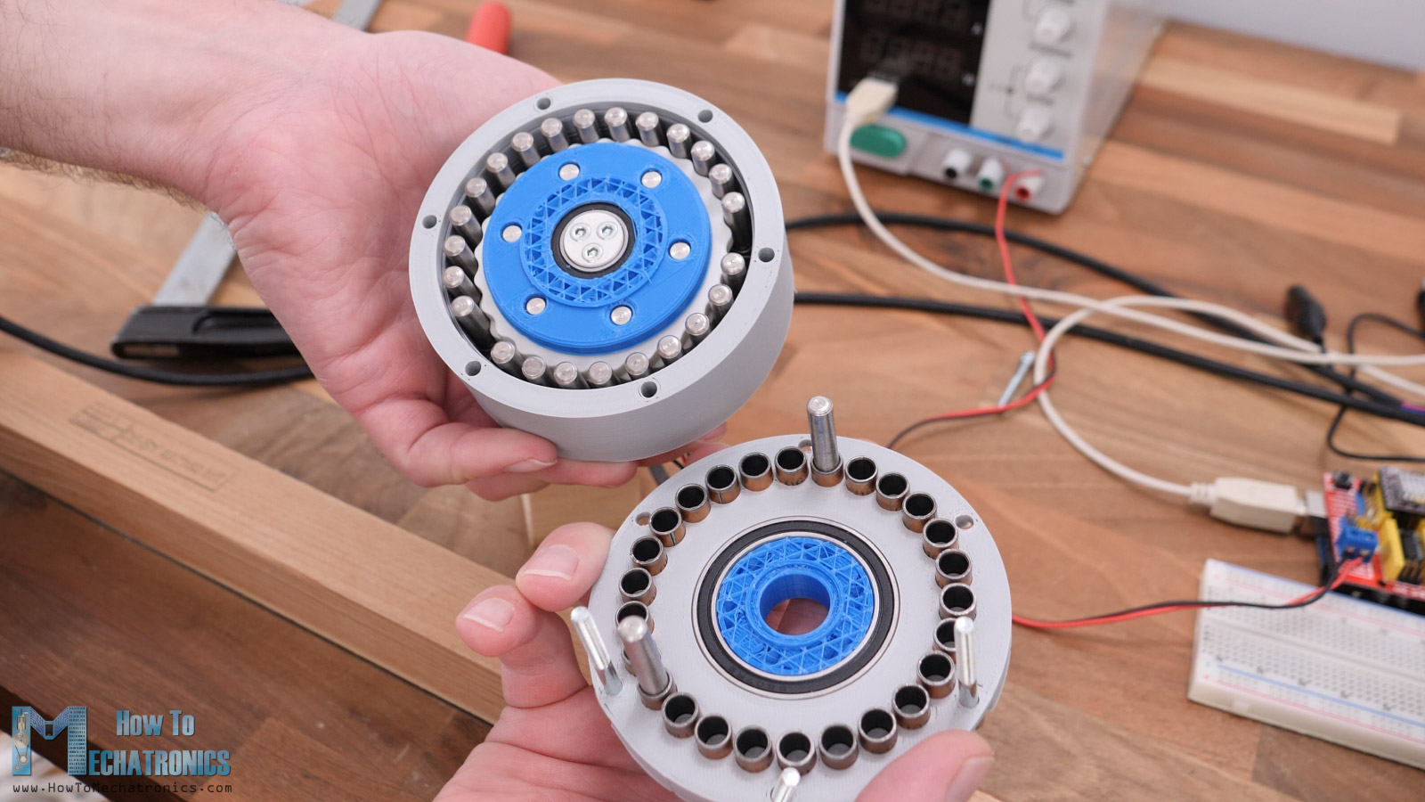
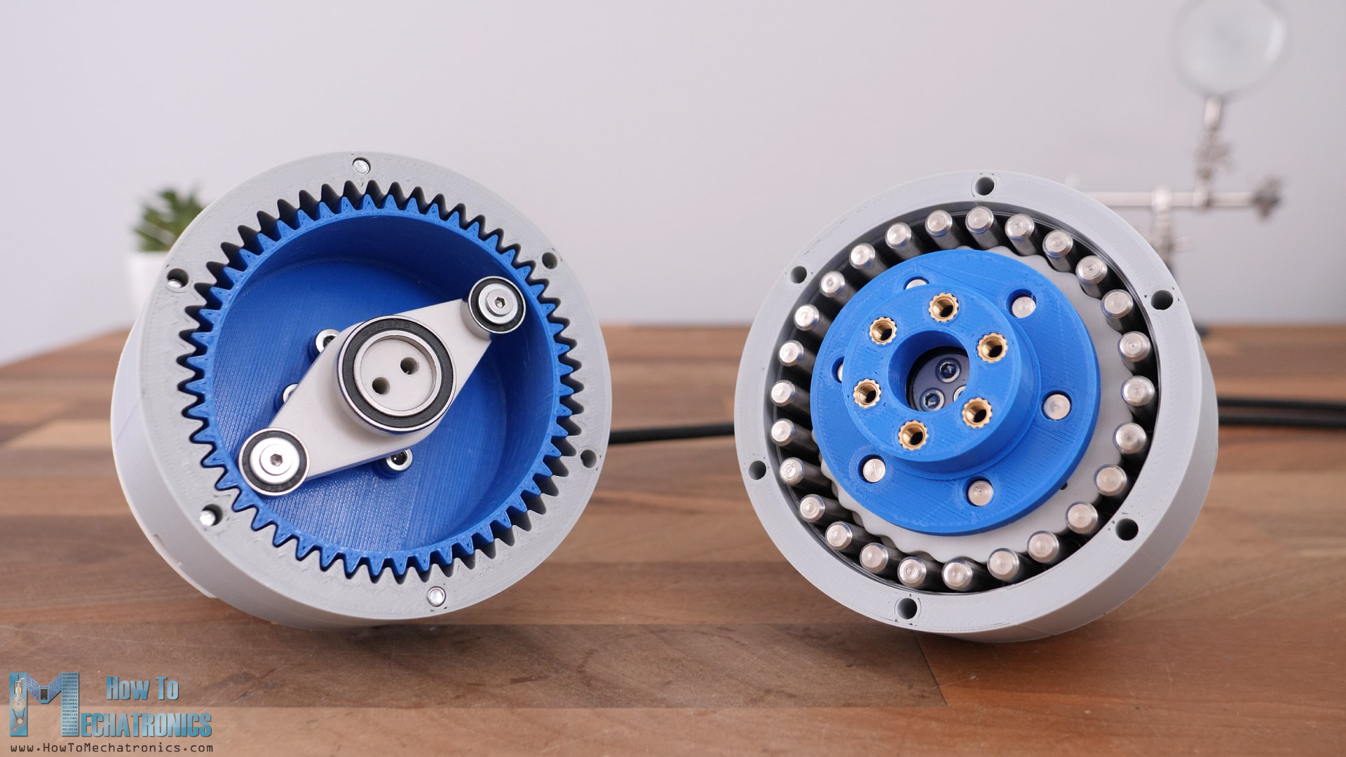
In this article we will find out what’s better, a 3D printed harmonic drive or a 3D printed cycloidal drive. Here I have these two gearboxes that I made which have the same size and reduction ration of 25:1. I will compare them in several categories, measure their efficiency or torque output, measure their accuracy or backlash, and see how durable they are.
You can watch the following video or read the written tutorial below.
I will explain how I designed and assembled both of them, and I will give you some useful tips and tricks for 3D printing them, show you what can go wrong and what can we improve to get them better, things that I have learnt along the way of making several of these.
Actually, this is my 4th video talking about these gearboxes, and why is so? Well, these gearboxes are good choice for robotics applications and in future videos I plan to make some robots that will employ this type of gearboxes.
Working Principle Overview
I already have dedicated videos on my channel explaining in details what are and how harmonic drive and cycloidal drive work, as well as how to design them, so I would suggest checking those tutorials out for more details.
Real quick, both the harmonic and the cycloidal drive are unique type of gearboxes, or speed reducers that provide very high reduction ratio with compact but robust design. Their working principle is kind of similar, where their input shaft, drives a non-regular shape part, a wave generator in case of the harmonic drive, and an eccentric bearing in the case of the cycloidal drive.
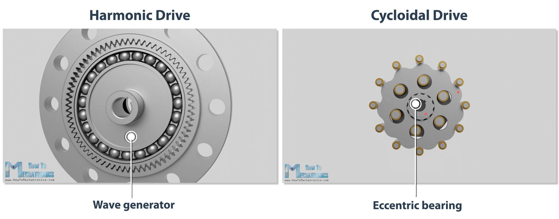
Then with the help of some more unique parts each gearbox has, they are able to generate output with significantly lower speeds in a very small space.
The reduction ratio of the harmonic drive is always half the number of the flex spline teeth. If we want 25:1 reduction ratio, we need 50 teeth on the flex spline and 52 teeth on the circular spline.
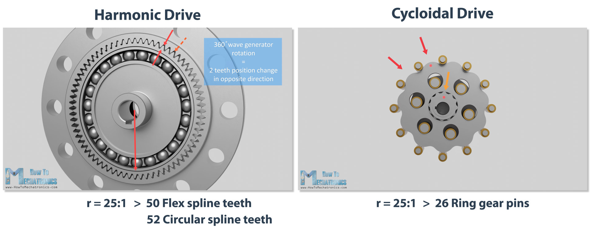
On the other hand, the reduction ration of the cycloidal drive is always one less than the number of pins on the ring gear, or for 25:1 reduction ration we need 26 pins on the ring gear.
Again, as I mentioned, you can check my dedicated videos for detailed explanation how these drives work.
Designing
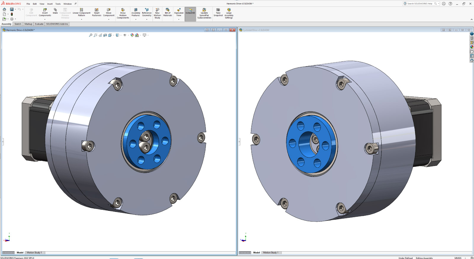
All right, so now let me show you how I designed the two gearboxes for this video.
So, my goal was to make them the same size and to have the same reduction ratio so that I can easily compare them head-to-head. I wanted to have 25:1 reduction ratio and make the gearboxes as small as possible.
Cycloidal Drive Design
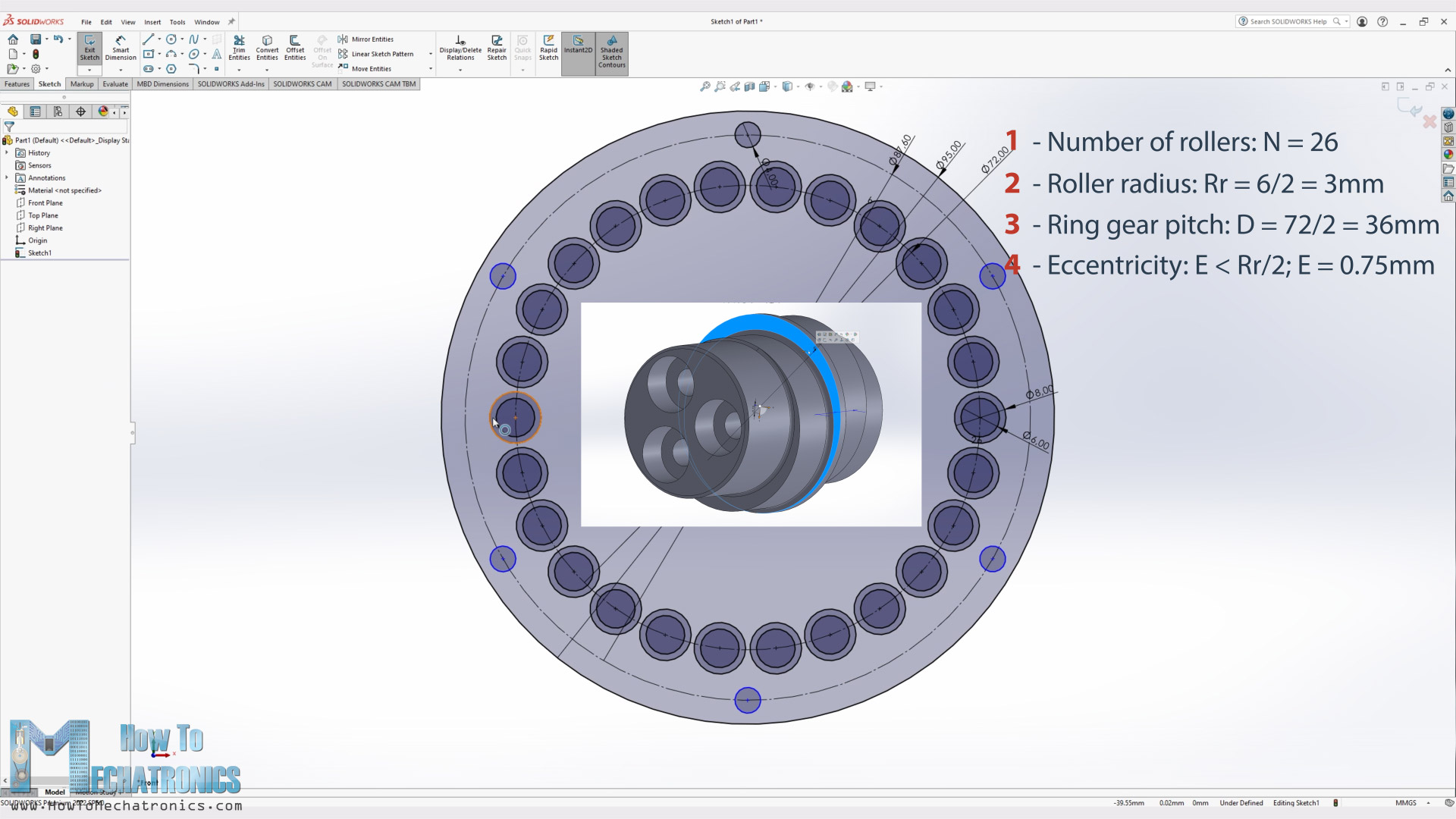
The base and first input parameter when designing these gearboxes was the size of the pins that I had for the rollers for the cycloidal drive ring gear. I had 6mm pins which I planned to put them in 8mm bushings in order to get smoother operation. So, I draw a sketch with 26 rollers and bushings with 8mm diameter.
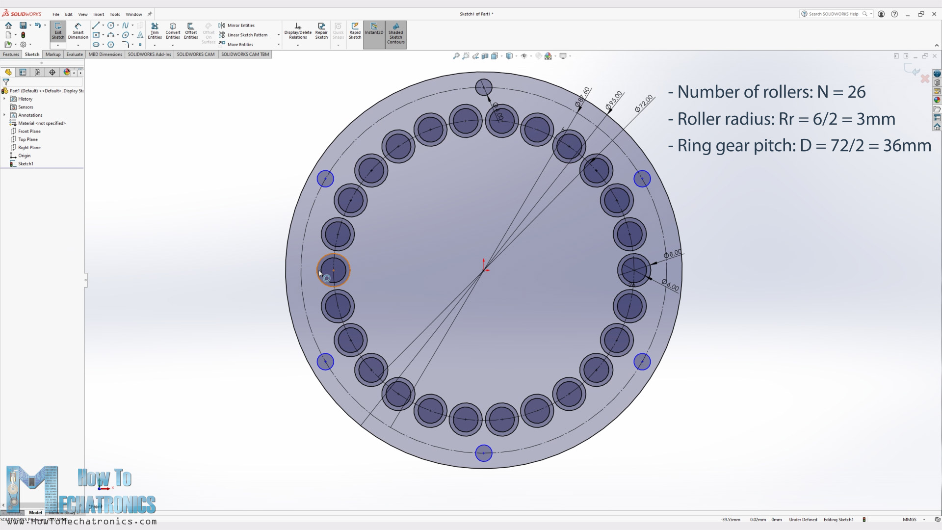
Now according to these two input parameters I could define the minimum size of the ring gear pitch diameter, which eventually defines the size of the gearbox. The housing diameter had to be 95mm in order to fit all 26 bushings and have enough wall thickness for some M4 bolts for assembling the whole gearbox.
For generating the cycloidal disk shape, we need one more input parameter and that’s the eccentricity value which should be smaller than half of the pin diameter.
For drawing the unique shape of the disk, we can use the following parametric equations which can be found in a document written by Omar Younis for the SOLIDWORKS education blog.
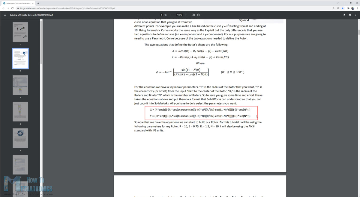
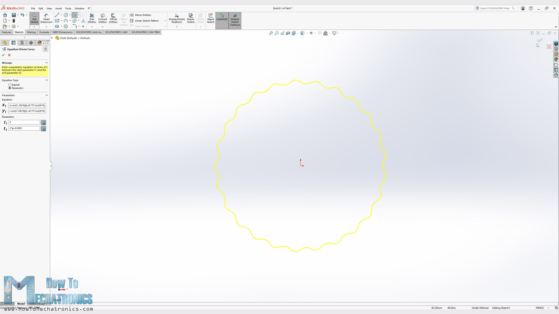
Now I will show you how I used these parametric equations for making the cycloidal disks using SOLIDWORKS and its Equation Driven Curve tool.
— Sponsored section —
“It’s worth noting here that these industry-leading and professional-grade design tools are now available to all makers at a remarkably low price of only $99 per year or $9.99 per month. That’s right, 3DEXPERIENCE SOLIDWORKS for Makers is great for anyone learning the trade, making DIY projects, and more.
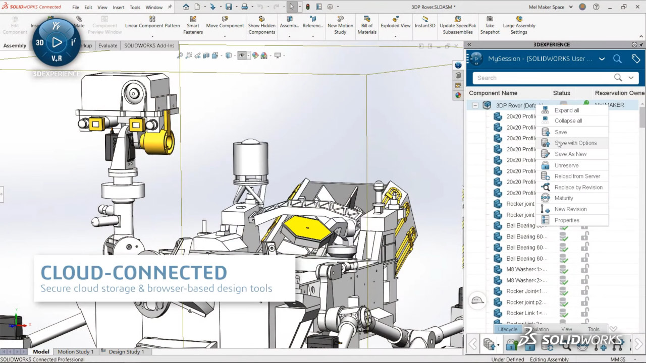
This offer includes 3DEXPERIENCE SOLIDWORKS Professional, the most in-demand CAD tool within the offer and runs locally on your PC. You can store files locally or in the cloud with the 3DEXPERIENCE platform.
“xDesign”, browser-based CAD, you can use it with 3DEXPERIENCE SOLIDWORKS, or on its own. It’s great for modeling anywhere, anytime, and on any device.
“xShape”, browser-based freeform CAD that’s easy to use for surface modeling on any device.
“Visualize Connected”, easily create photo-quality images, animations, interactive web content and more to impress your audience.
“NC Shop Floor Programmer”, CAM for intelligent machining strategies for 3-axis milling and wire EDM in an easy use package.
Click the link below, and you’ll get a special 20% off – so you can start making with the best today! Big thanks to SOLIDWORKS for sponsoring and supporting education content like this. ”
Buy Now: http://www.solidworks.com/makers20
Learn more: https://discover.solidworks.com/3dexperience-solidworks-makers
— Back to topic —
Back to topic, we can easily generate the cycloidal disk shape by inserting the two parametric equations in place. Of course, we should use our parameters in the equations appropriately.
Here’s the equations:
Equations by Omar Younis

N - Number of rollers
Rr - Radius of the roller
R - Radius of the rollers PCD (Pitch Circle Diamater)
E - Eccentricity - offset from input shaft to a cycloidal disk

x = (R*cos(t))-(Rr*cos(t+arctan(sin((1-N)*t)/((R/(E*N))-cos((1-N)*t)))))-(E*cos(N*t))
y = (-R*sin(t))+(Rr*sin(t+arctan(sin((1-N)*t)/((R/(E*N))-cos((1-N)*t)))))+(E*sin(N*t))

i = 25:1
N - 26
Rr = 6/2 = 3
R= 72/2 = 36
E = 0.75

x = (36*cos(t))-(3*cos(t+arctan(sin((1-26)*t)/((36/(0.75*26))-cos((1-26)*t)))))-(0.75*cos(26*t))
y = (-36*sin(t))+(3*sin(t+arctan(sin((1-26)*t)/((36/(0.75*26))-cos((1-26)*t)))))+(0.75*sin(26*t))Code language: JavaScript (javascript)
As for the “t” parameters, we should use the value from 0 to 2*Pi. Though, we should note that we need to use a slightly smaller value than 2*Pi, in order the curve to be generated. This will generate the curve with a little gap which can be than easily connected with a spline.
Then we can simply extrude the profile, and make the holes for the eccentric bearing and the output pins. The diameter of these output holes is equal to the pin rollers diameter + two times the eccentricity. In this case that’s 8 +0.75*2 = 9.5mm diameter.
So, the cycloidal disk, along with the eccentric bearing and the ring gear rollers are the most important parts of the gearbox, and the rest of the parts are designed around them.
The design of the gearbox depends on many factors such as the motor type, how we would like to drive the input shaft, what kind of bearings we have available to work with, the application of the gearbox itself and so on.
Harmonic Drive Design
Nevertheless, let’s take a look at the harmonic drive now. As I mentioned, the idea was both gearboxes to have the same size, which I was able to get it in terms of the gearbox diameter, but the length had to be a bit longer, in order to accommodate the flex spline.
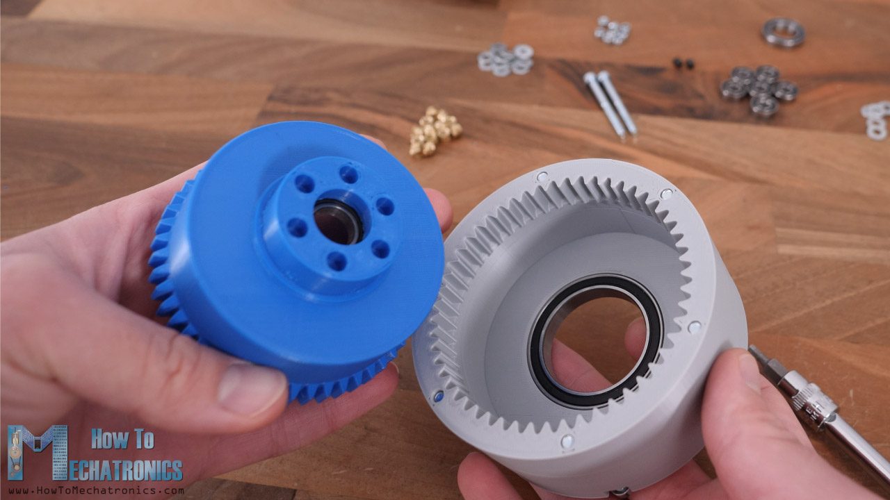
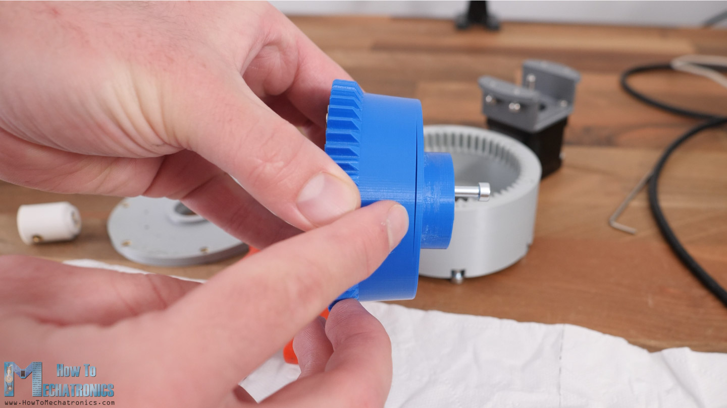
Here we have the flex spline which is very unique part because it has to be flexible at the open end but rigid at the bottom or the output.
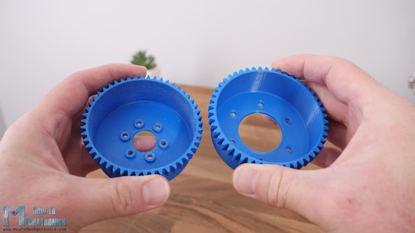
If we try to make the cup shorter in order to match the length dimension of the cycloidal gearbox, it won’t work properly as we are using PLA material which doesn’t have enough flexibility and its tin wall would easily break.
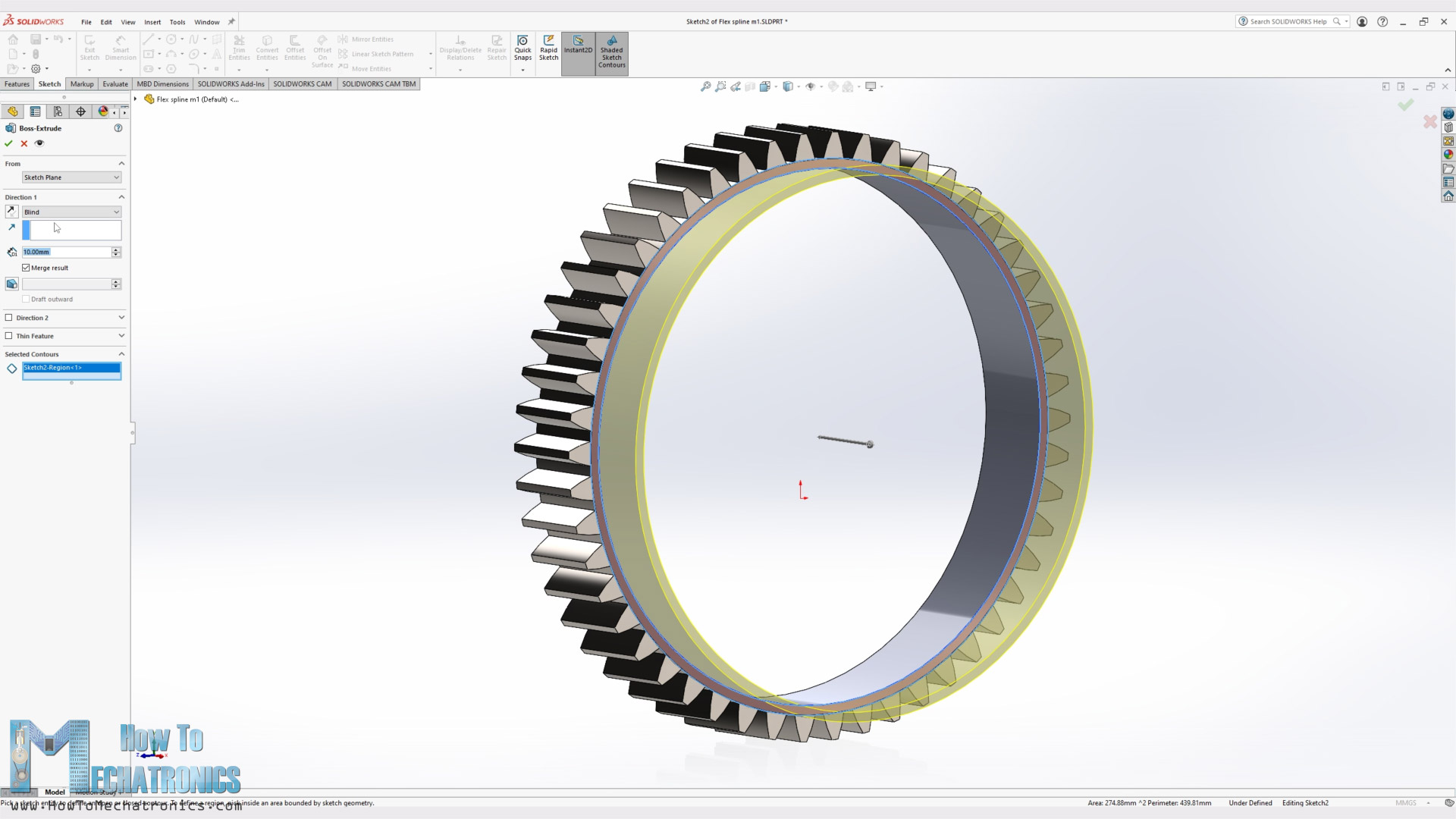
For designing the flex spline, I used the SOLIDWORKS Toolbox to generate a spur gear with 50 teeth. I chose a module of 1.5 which gave me a dimension suitable to match with the cycloidal gearbox. I saved it as a separate part file, and then started modifying it. I made the wall of the cup to be 1.25mm and the total length of the cup to 30mm.
As for the circular spline, I used the same method. With the SOLIDWORKS Toolbox I generated an internal spur gear with 52 teeth this time, and then modified it according to the rest of my gearbox design. I made a slight clearance of 0.1mm inside the gear just to be sure that the gears will mesh, because it’s a bit hard to get very accurate 3D printed parts.
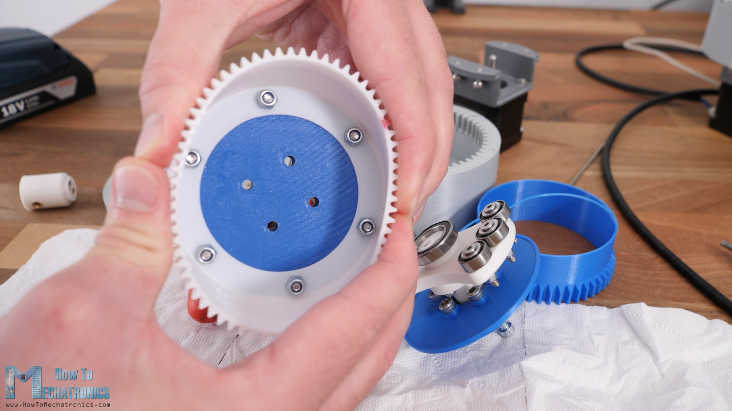
Then for the third key component of the harmonic drive, the wave generator, I draw an ellipse with the major axis 3.2mm larger than the inner wall diameter of the flex spline, and the minor axis 3.2mm smaller.
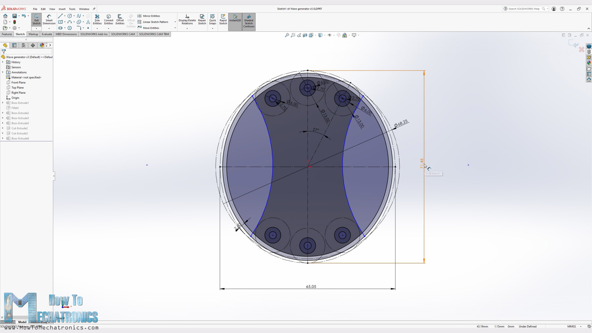
Now according to this ellipse, I arranged 3 bearings at each side of the major axis in order to achieve a smoother deformation of the flex spline. In commercially available harmonic drives, they use a special flexible ball bearing here, but they expensive and are hard to find.
The rest of the harmonic drive was designed according to these three key components.
3D Model and STL Files Download
You can download the 3D Models of these harmonic and cycloidal drives, as well as the STL files needed for manufacturing below:
SOLIDWORKS files:
STL files:
3D Printing
When 3D printing, in order to get accurate dimensions of the parts, we need to have proper settings in our slicing software. The most important settings for getting dimensionally accurate prints are the Horizontal Expansion and Hole Horizontal Expansion settings.
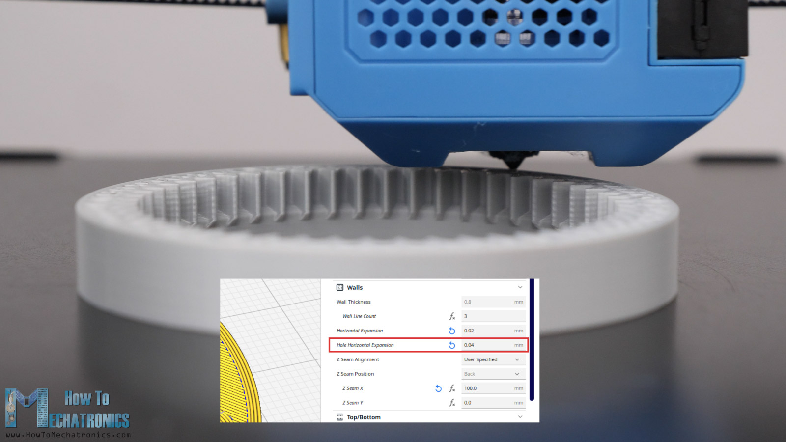
If we leave these settings by default, the prints outer dimensions as well as the holes are usually smaller than the original model. I set the Horizontal Expansion to 0.02mm and the Hole Horizontal Expansion to 0.04mm. Of course, you should do some test prints to see what values will give you the best results on your 3D Printer.
Though, for some of the parts I used different values for these settings. For example, for the flex spline and the cycloidal disks I used a value of –0.01 and –0.02mm for the Horizontal Expansion setting. This way we will be sure that the print will be definitely smaller than the original, as these parts must have a clearance fit to be able to move.
Assembly
Ok, so here I have all of the parts ready and I moved on with assembling the gearboxes.
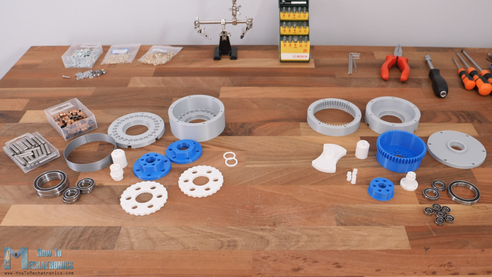
In order to not overload this video, I will walk you through the assembling process a bit quicker than usual. I will just point out the important aspects of it.
Cycloidal Drive Assembly
Here’s a list of all components needed for assembling the cycloidal drive:
- 6mm Steel Cylinder Rod …………………..…. Amazon / AliExpress
L=30mm x26 pcs; L=22mm x6 pcs for one drive - 8mm Bushings ………………………………………. Amazon / AliExpress
L=20mm x26 pcs; L=15mm x6 pcs for one drive - Ball Bearing 35x47x7mm 6807 – x2 …… Amazon / AliExpress
- Ball Bearing 17x26x5mm 6803 x2 ……… Amazon / AliExpress
- Ball bearing 15x24x5mm 6802 – x2 ….. Amazon / AliExpress
- Threaded inserts M4x5mm ………….……. Amazon / AliExpress
- M3 and M4 bolts and nuts ………………….. Amazon / AliExpress
List of bolts: M3x8mm – 8pcs, M3x25mm – 3pcs; M4x10mm – 4pcs; M4x35mm – 6pcs
Disclosure: These are affiliate links. As an Amazon Associate I earn from qualifying purchases.
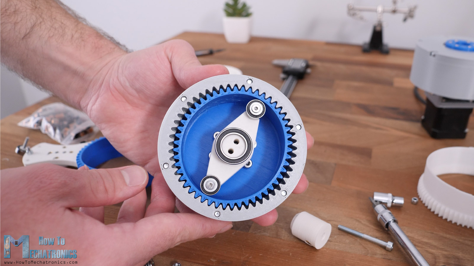
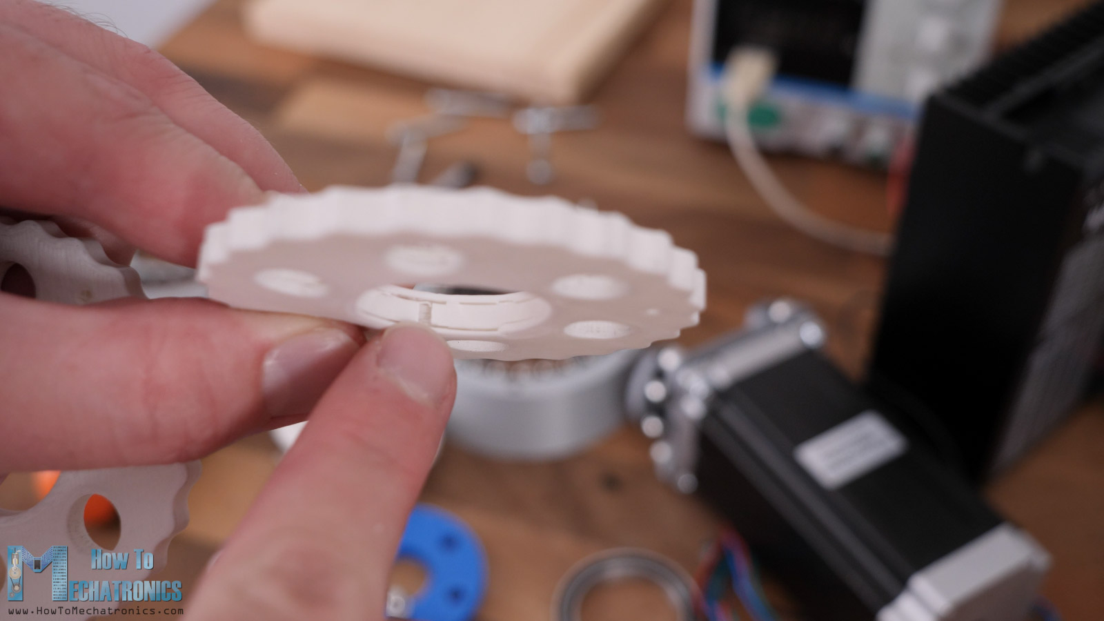
When assembling the cycloidal drive, the most crucial thing is to make sure that we place the two cycloidal disks 180 degrees out of phase.
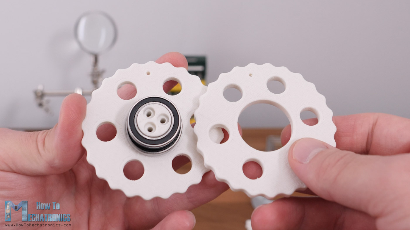
I made a small hole on the disks which can help us with that. We should position the holes 180 degrees apart, or if we flip the disks, we can just align two holes and that will get us the 180 degrees out of phase positioning.
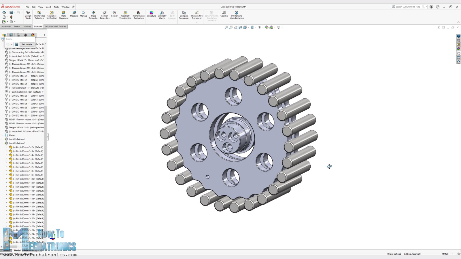
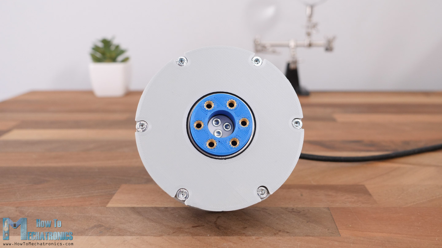
Here’s how two cycloidal disks in combination with the output shaft look when assembled.
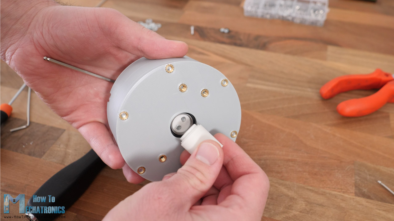
On the eccentric shaft we can attach and secure any input shaft coupler using tree M3 bolts. In this case I placed one for a NEMA 17 stepper motor.
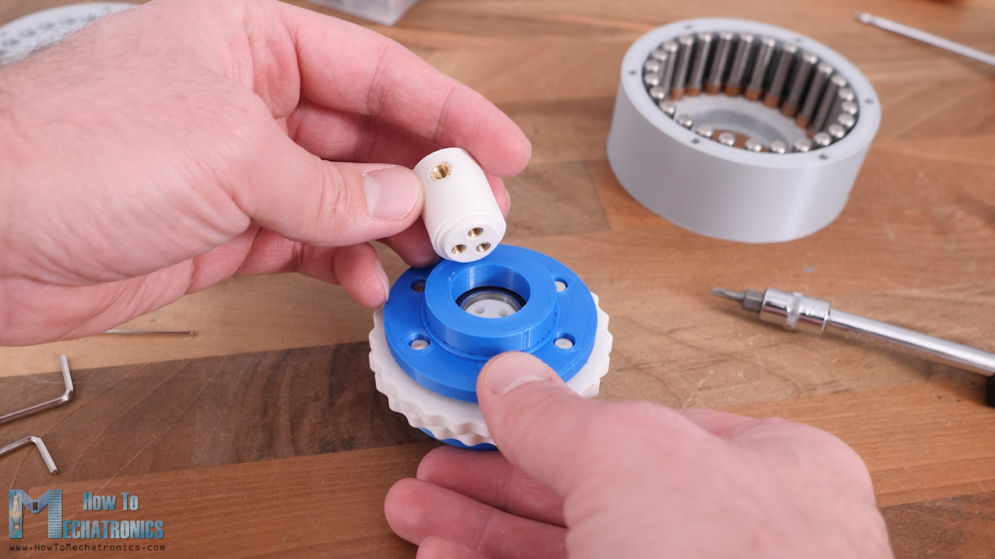
Though, we can note here that fastening these bolts can be a bit messy, because the holes on the eccentric bearing are small so that the bolts can make a thread into them and have tight fit to avoid any backlash from here. It’s probably not the best solution but it will work.
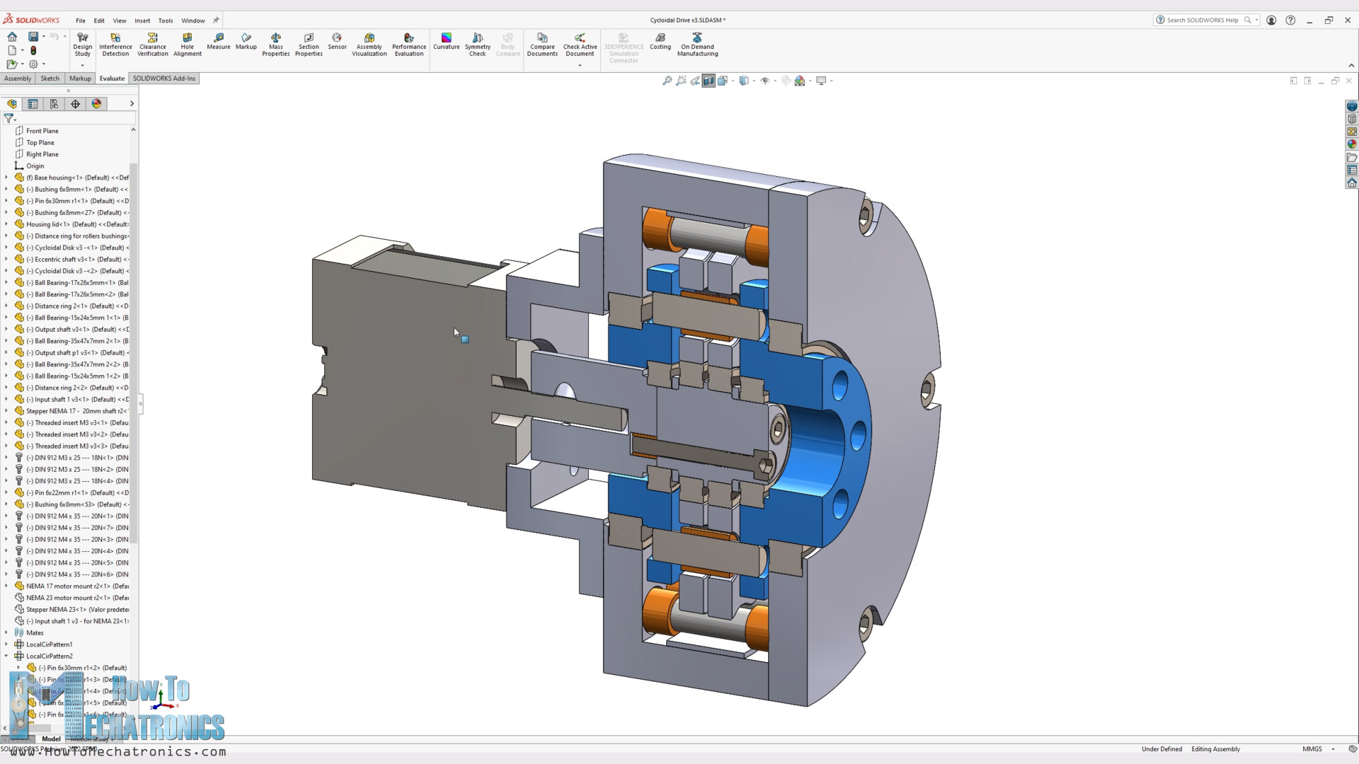
Once we place this sub-assembly into the gearbox, we can see the magic of the cycloidal drive and how it works.
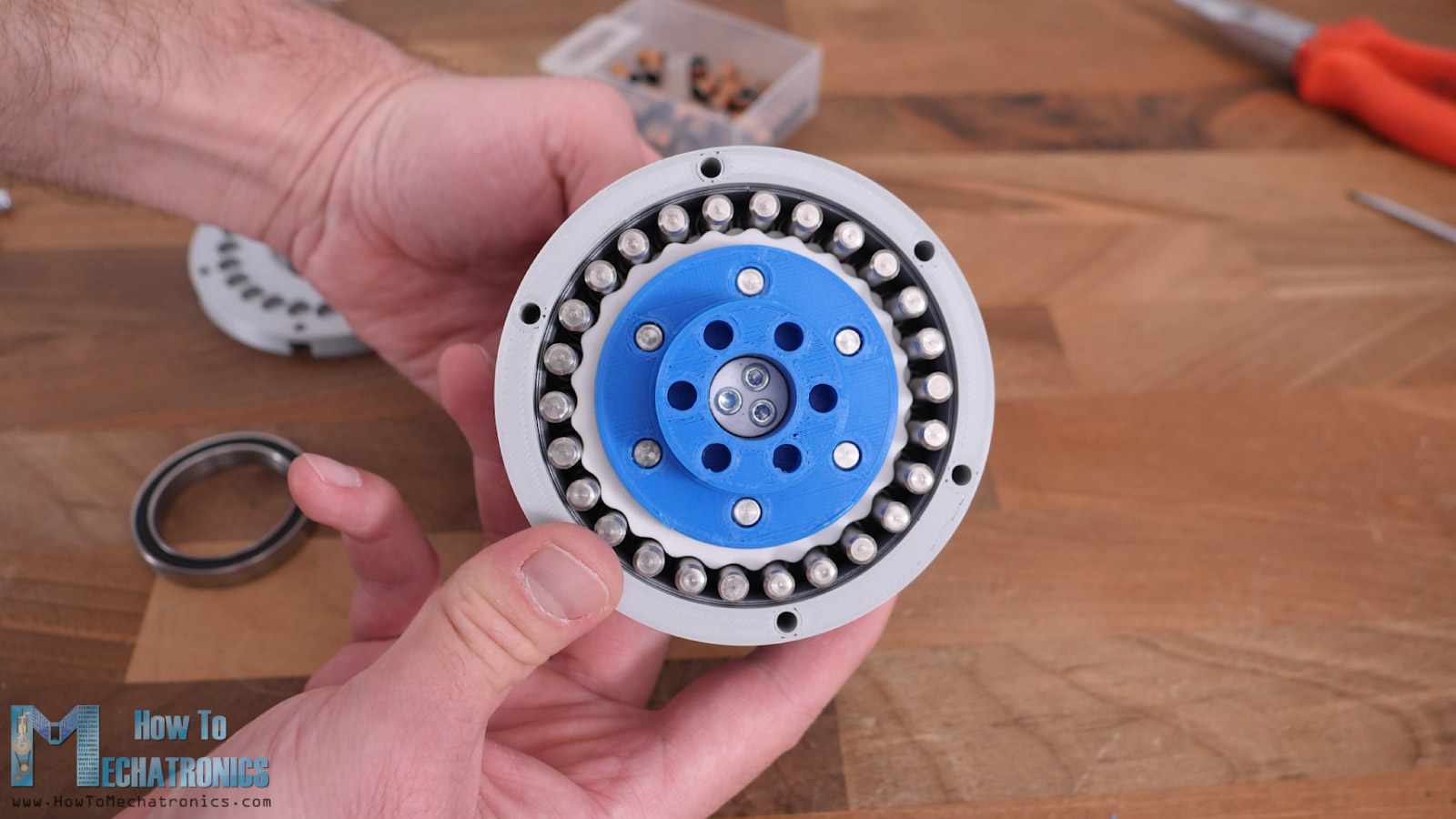
At this point it seems that it works quite smoothly.
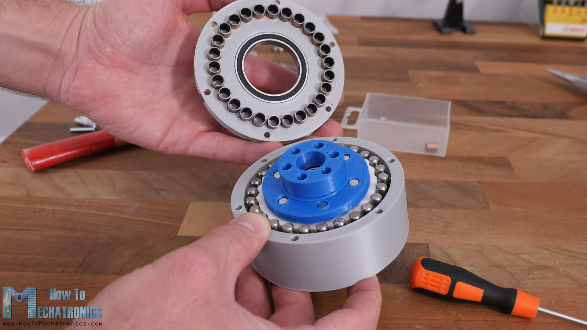
When inserting the lid in place, we should make sure we align the bushings with the pins as well as the six holes that are used for securing them in place.
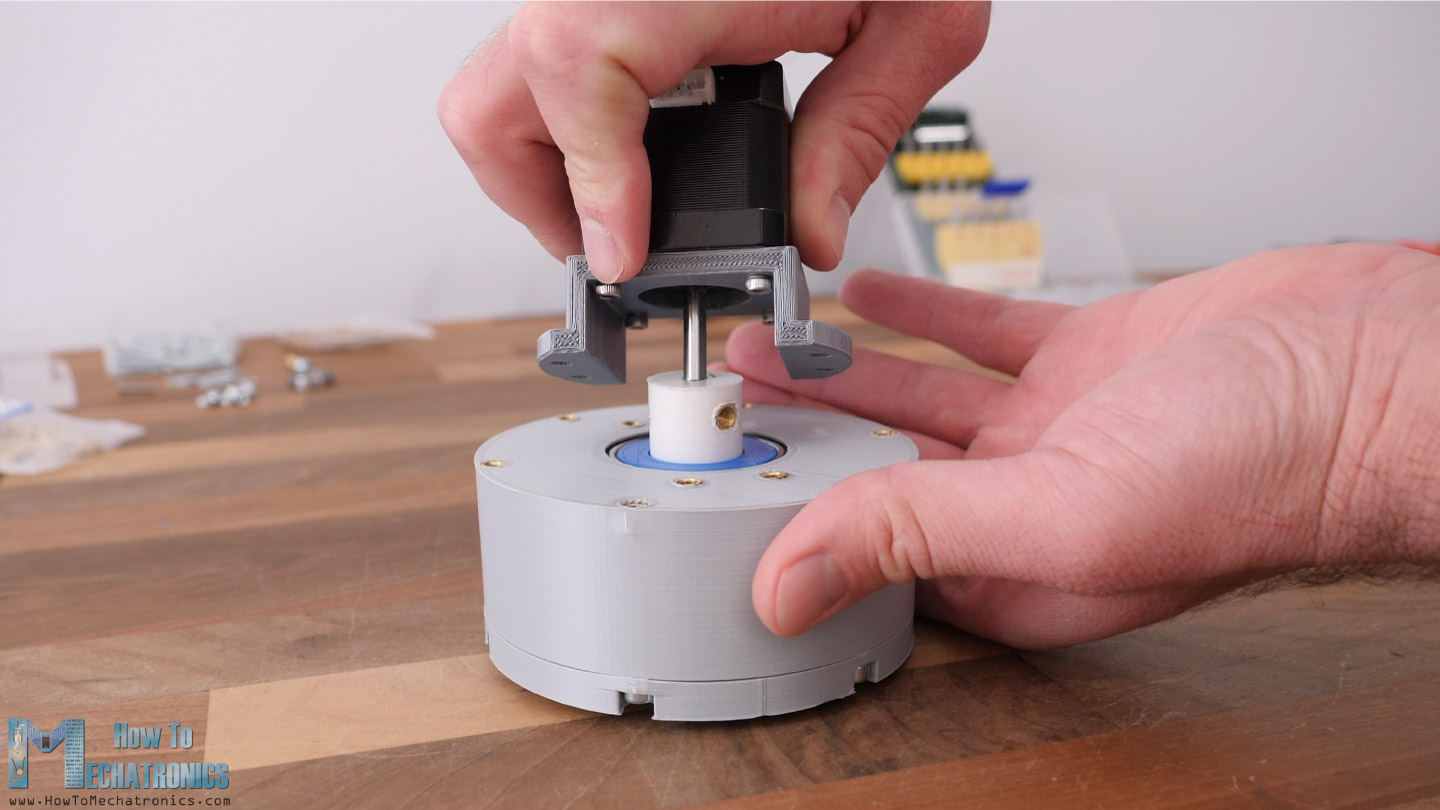
Lastly, we can attach the NEMA17 stepper with the help of this mounting bracket. Of course, we can change the input shaft coupler and the mounting bracket to fit with any other motor.
And here it is. You can take a look how smooth it works in the video. The output shaft rotates 25 times slower than the input shaft in the opposite direction.
Harmonic Drive Assembly
All right, so next is the harmonic drive. The harmonic drive assembly is a bit quicker as it has less parts compared to the cycloidal drive.
Here’s a list of all components needed for assembling the cycloidal drive:
- Ball Bearing 35x47x7mm 6807 – x1 …… Amazon / AliExpress
- Ball bearing 15x24x5mm 6802 – x1 ….. Amazon / AliExpress
- Ball bearing 12x21x5mm 6802 – x1 ….. Amazon / AliExpress
- Threaded inserts M4x5mm ………….……. Amazon / AliExpress
- M3 and M4 bolts and nuts ………………….. Amazon / AliExpress
List of bolts: to be updated soon.
Disclosure: These are affiliate links. As an Amazon Associate I earn from qualifying purchases.
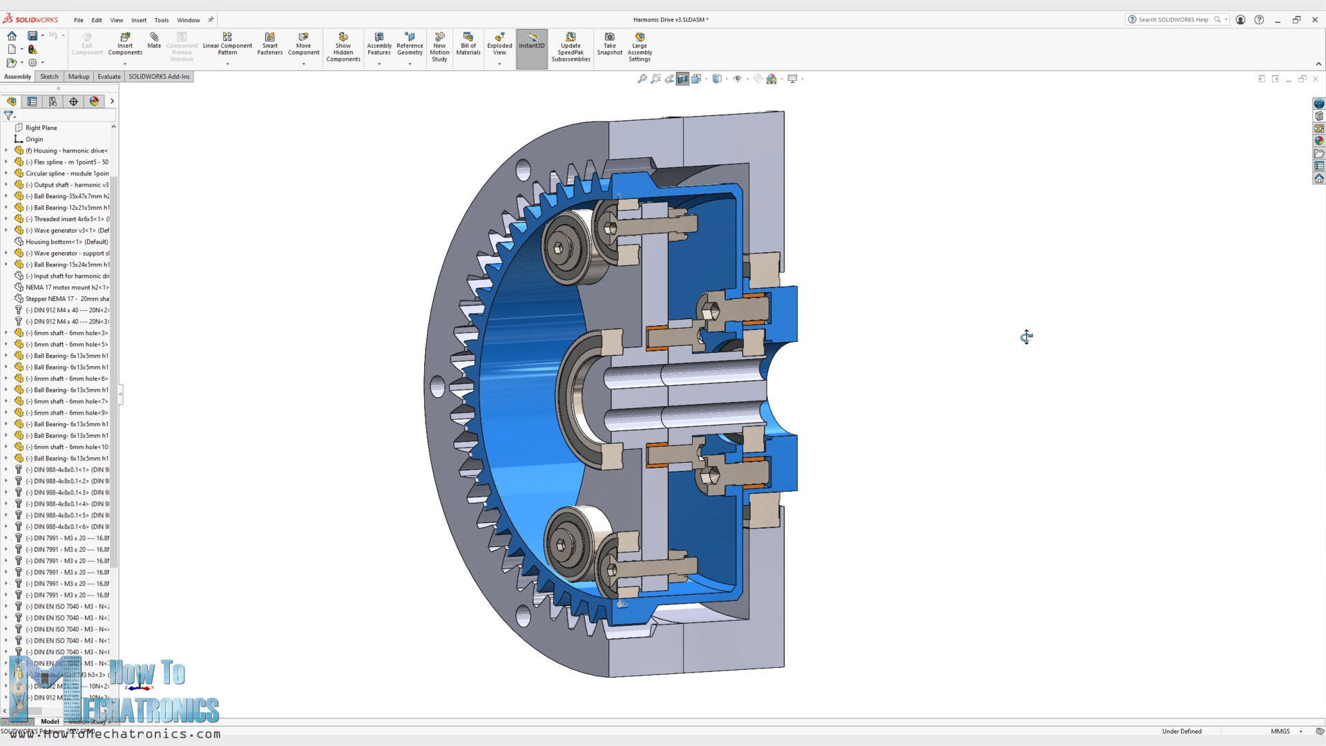
The output shaft is secured to the flex spline, which is than inserted into the circular spline.
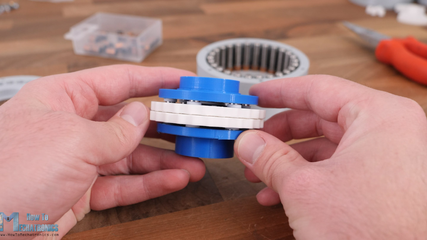
The wave generator is composed of two sections which should be secured together with four M3 bolts. I designed it this way so that it has support on both side of the gearbox with bearings.
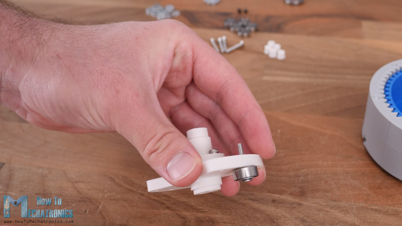
The wave generator bearings that will roll on the inside and deform flex spline are with 6mm inner and 13 mm outer diameter. I secured them in place using some M3 countersunk bolts and M4 washers. The reason for that is to save on space as much as possible.
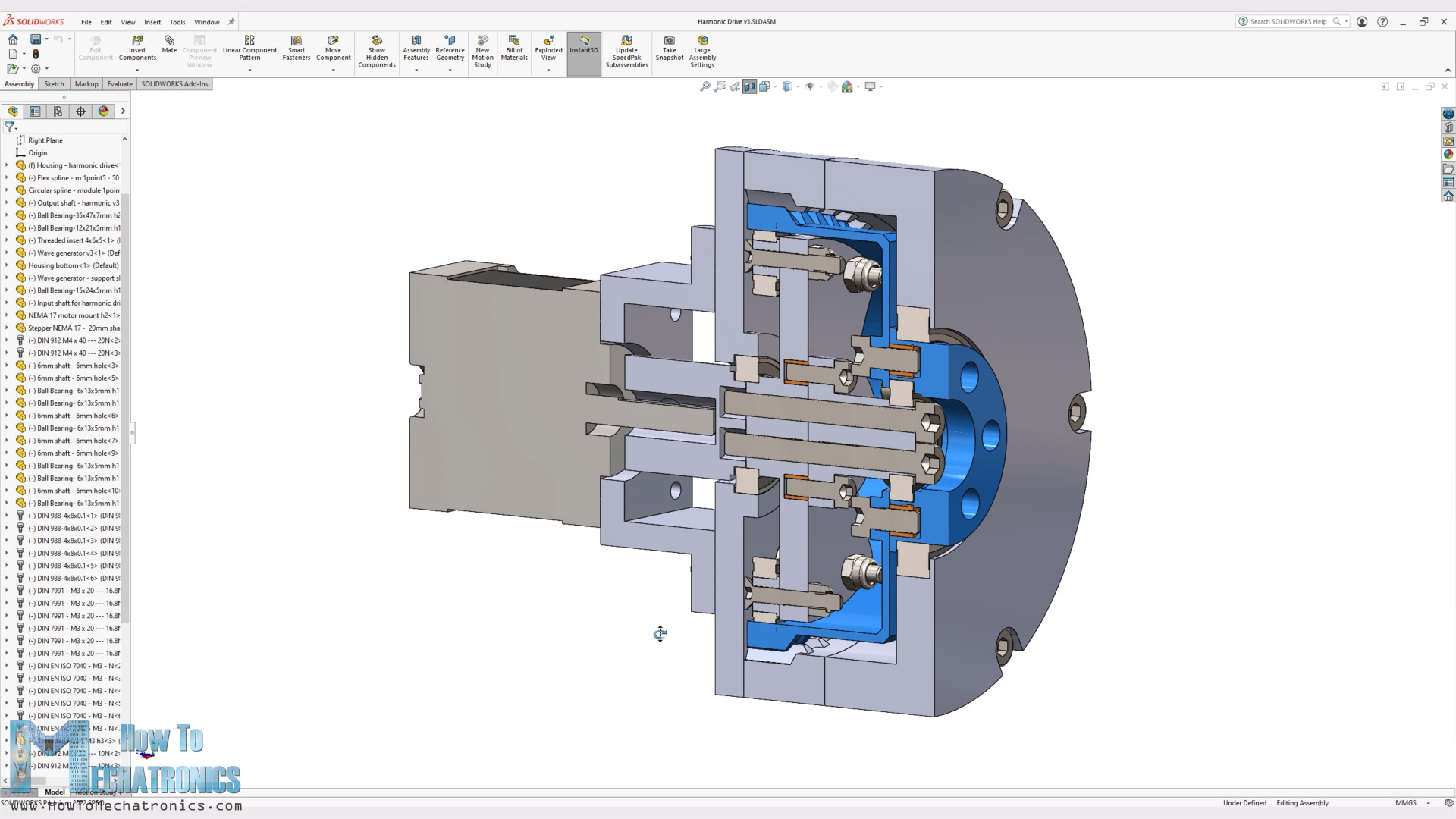
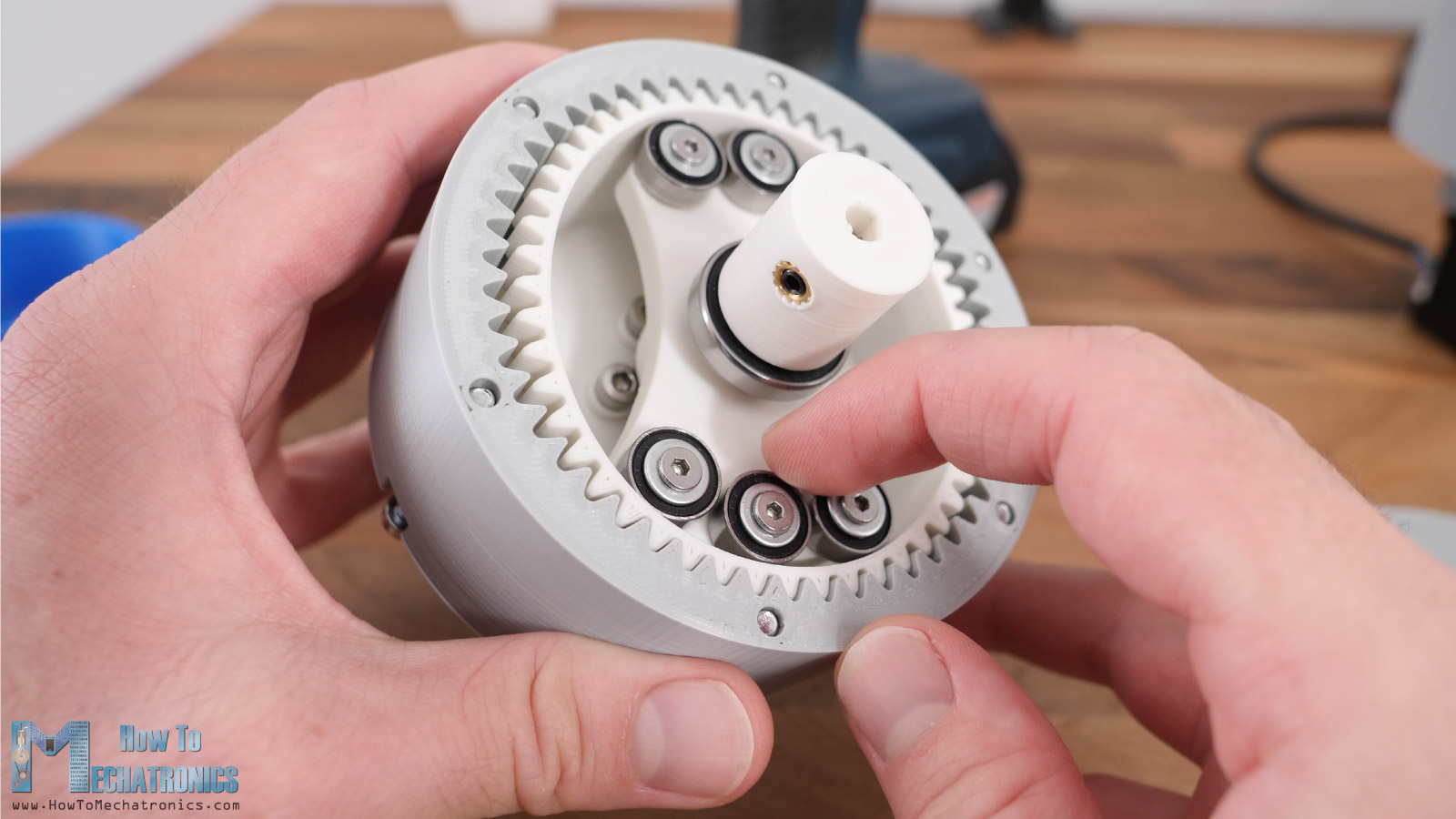
Then I inserted the wave generator into the flex spline with a little bit of squeezing.
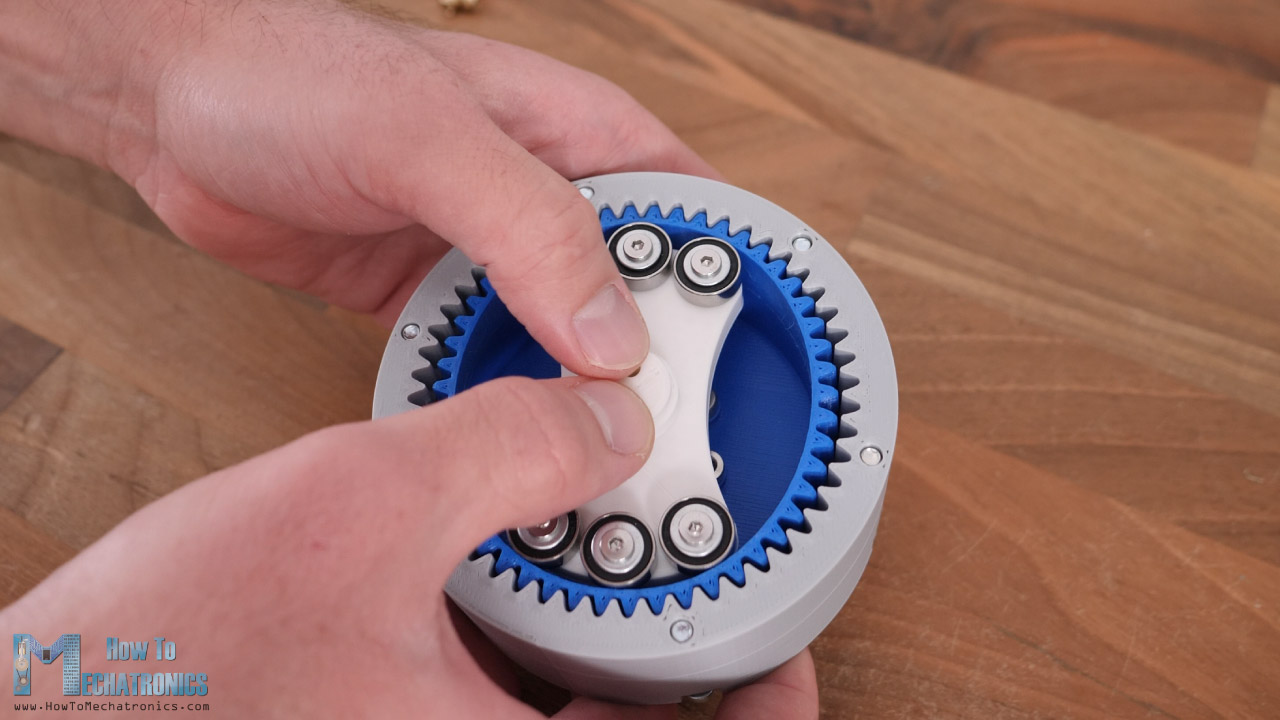
Actually, it’s much easier to first put the wave generator into the flex spline, and then put those two into the circular spline. At this point we can see how it works by moving the wave generator by hand, though we can notice that the movement is a bit jerky and we will see why a bit later.
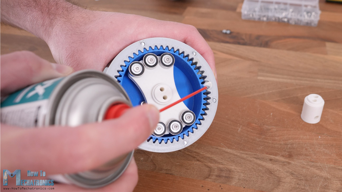
I applied some lubrication to the gear meshing which improved the motion a little bit.
The gearbox housing is completed with inserting the lid at the back side and securing it with six M4 bolts. Then we just have to attach the input shaft coupler that we want, and in this case that’s again for a NEMA 17 stepper motor.
Lastly, I attached and secured the NEMA 17 stepper motor with the mounting bracket, and with that the harmonic drive was completed.

So, here it is, the output shaft rotates 25 times slower than the input shaft in the opposite direction, but compared to the cycloidal disk the motion doesn’t seem to be that smooth.
Troubleshooting
Compared to the cycloidal disk, the motion of the harmonic drive doesn’t seem to be that smooth. There are actually several reasons for that and now I will show you them. The first reason is that the flex spline was already broken.
The cup wall is just to tin to withstand that amount of deformation. The problem here is not just that the wall is too tin, but also the fact that the cup is too small in order to accept that kind of deformation. If the cup was a bit bigger, which was the case in the design from my other harmonic drive video, it would be able to elastically deform much better.
The length of the flex spline is even more important in order to get better results. However, here I was trying to make the two gearboxes to have the same size so I kept trying to get it working like this.
I tried 3D printing it with another filament and with increased wall thickness of 3 lines this time, but it failed quickly again.
The second problem was that the wave generator was not making the right contact with the flex spline. We can notice here how the top bearing is not touching the flex spline at all, only the two others were making contact.
So, I modifying the wave generator to have only one bearing and that improved the motion.
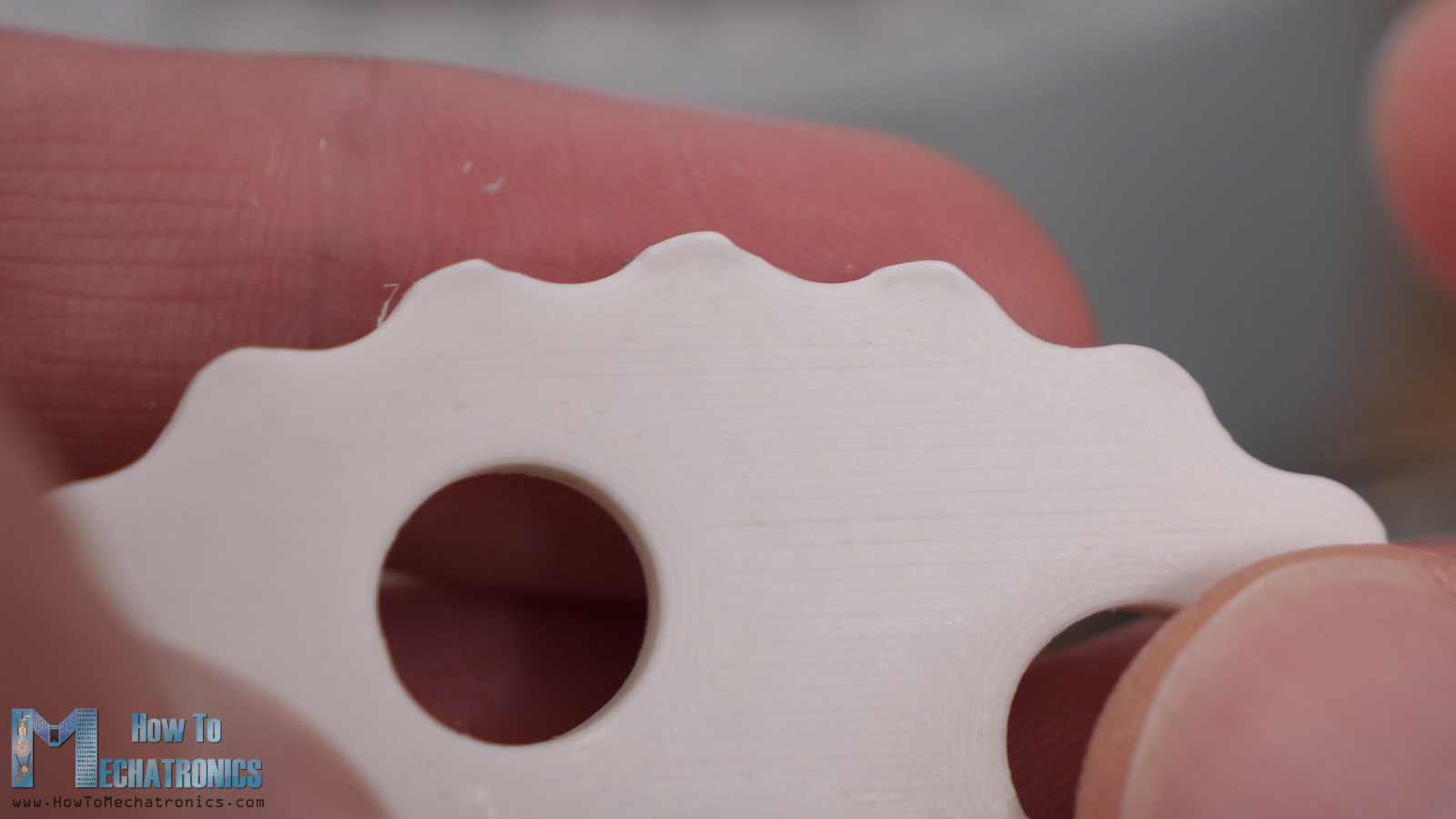
Another thing that was causing problem was that the inside surface of the flex spline where the bearing was in contact, was not that smooth. That’s because of the tin wall, and because when 3D printing, only 1 wall line was passing behind the teeth of the flex spline, and the surface was not smooth because of that.
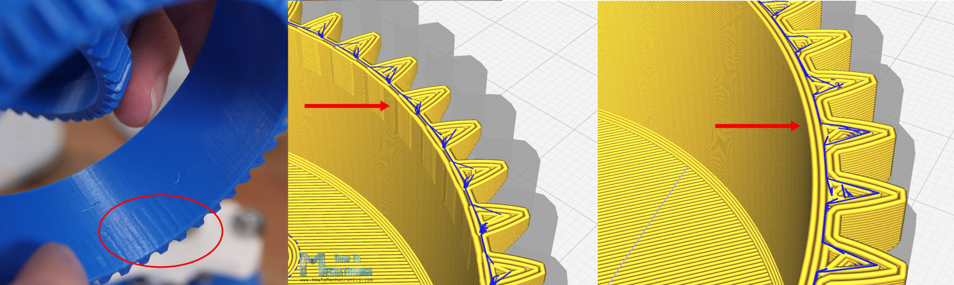
By increasing the wall thickness to accommodate one more wall line when 3D printing, the surface got much smoother. So here I’m using a wall thickness of 4 lines or 1.6mm thickness and the motion was improved.
However, there was one more problem. In my slicing software, for the Z Seam Alignment I was using “User Specified” which meant that the starting point of each path was at the same location and that was causing the part to have one more noticeable bump on the surface.
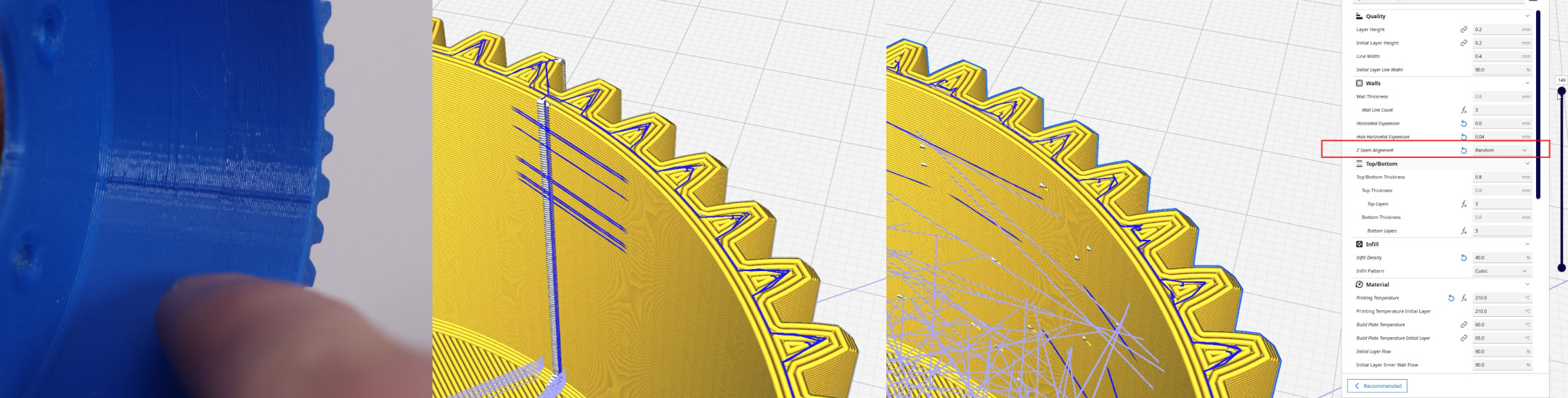
In order to avoid this, I set the Z Seam Alignment to “Random” and I got again a smoother surface and better motion.
Harmonic vs Cycloidal – Comparison
All right, so now let’s how the two gearboxes compare to each other, in terms of accuracy, efficiency and durability.
Backlash
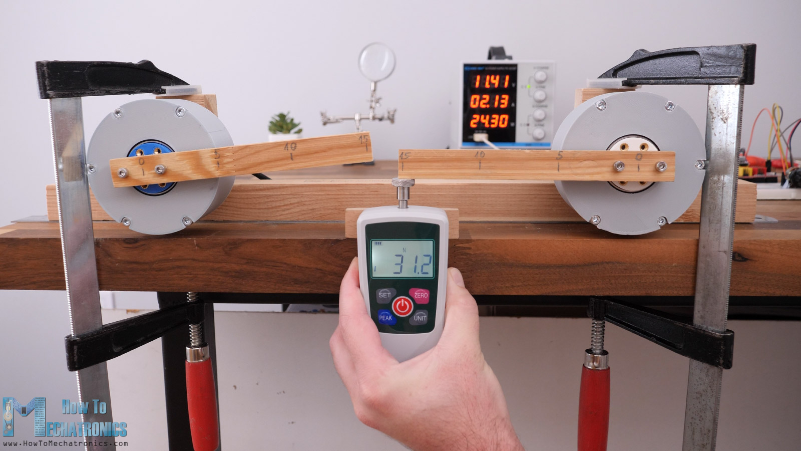
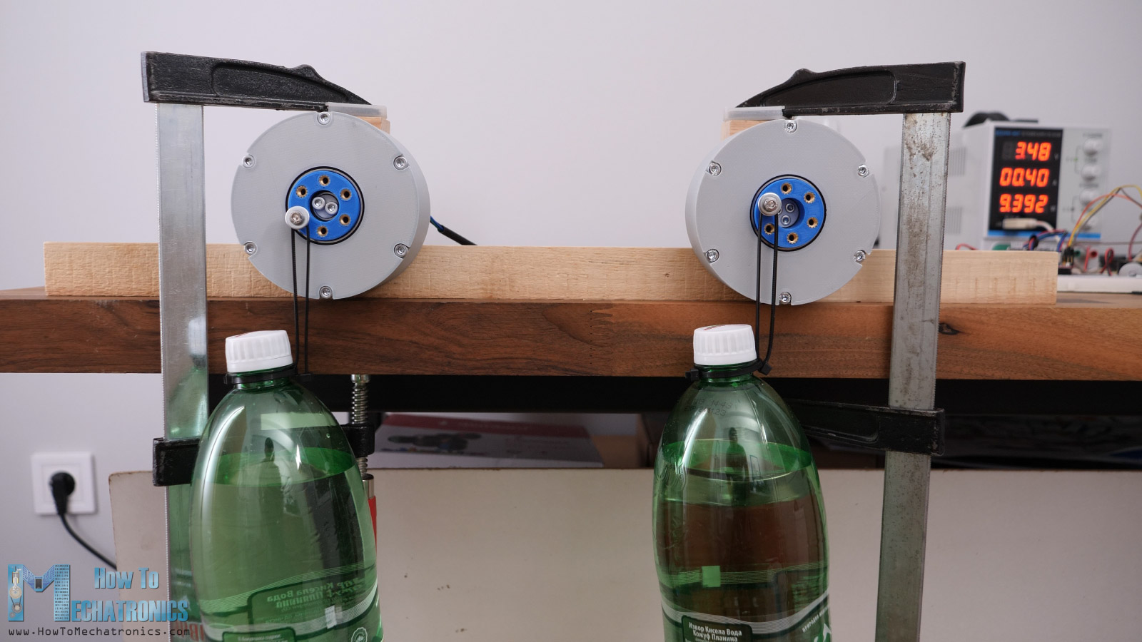
Here on the left side is the harmonic drive and on the right side is the cycloidal drive. The repeatability of the cycloidal drive is quite good, but once we apply a load, we can see the backlash it has.
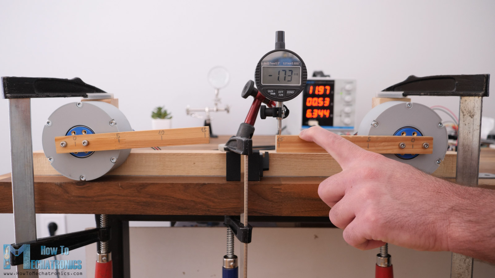
At a distance of 15cm, with applied force in both directions, there was around 6.5mm play.
On the other hand, the harmonic drive had the same good repeatability as the cycloidal drive. However, when force applied in both directions it showed a greater backlash, with 8 mm play at a distance of 15cm.
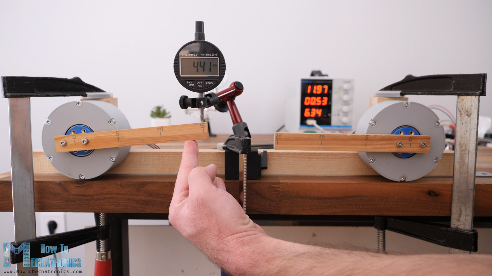
If we observe the backlash in still position and with applying just a small amount of force, then the harmonic drive was showing kind of better results. Here it felt like even there is no backlash at all, because even with the slightest touch the output was giving some resistance. On the other hand, on the cycloidal drive these was around 2mm of totally free play of the output at the same distance of 15cm.
However, when applied a bit larger force, the cycloidal drive showed slightly better results, or 5.5mm play whereas the harmonic drive showed up to 7mm of play.
Torque
Ok, let’s take a look at the torque outputs now. Here’s the first try of the cycloidal drive and bang. 22N at a distance of 15mm and something just broke.
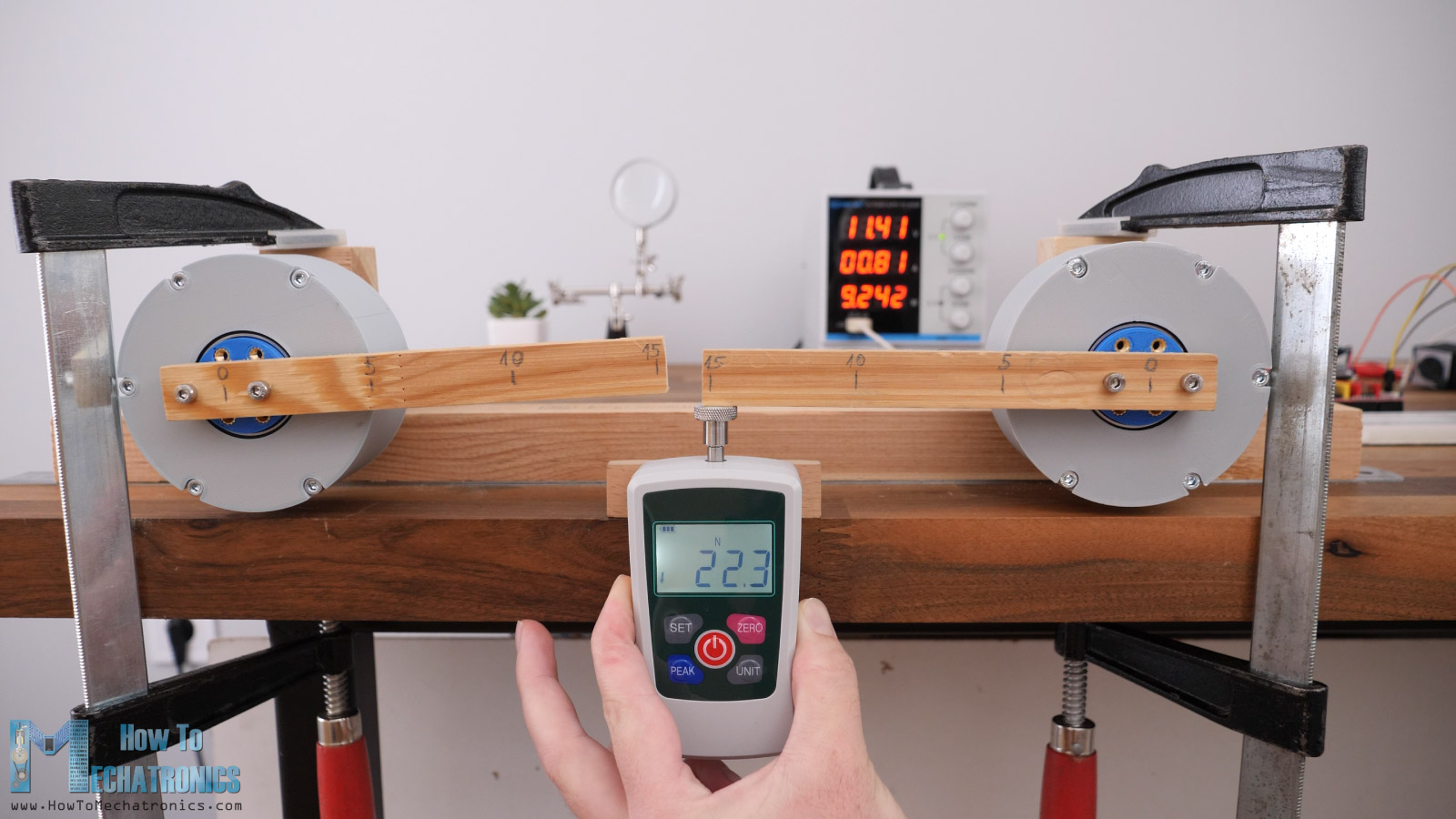
I took the lid out and that was the output shaft that broke. I printed a new one in white PLA now and with higher Infill Density and higher temperature to get the part stronger.
So, with the next run nothing broke and it maxed out at 32N at a distance of 15cm, or that’s a torque of 4.8Nm.
Compared that to the torque this NEMA17 stepper motor provides without the gearbox, around 2N at a distance of 15cm, or 0.3Nms of torque, that’s increase of around 16 times. That’s efficiency of around 65%, as the reduction ration is 25:1 and in ideal conditions we should get 25 times torque increase, but we got only 16 times increase.
The harmonic drive gave exactly the same result of 32N at a distance of 15cm, or 4.8Nm of torque. Again, that’s the same efficiency of around 65%. To me that was a bit of a surprise, as I expected that the harmonic drive to be even less efficient than the cycloidal drive.
So, as the NEMA17 maxed out at 4.8Nm, I replaced it with one big NEMA23 stepper by changing the input shaft and the mounting bracket.
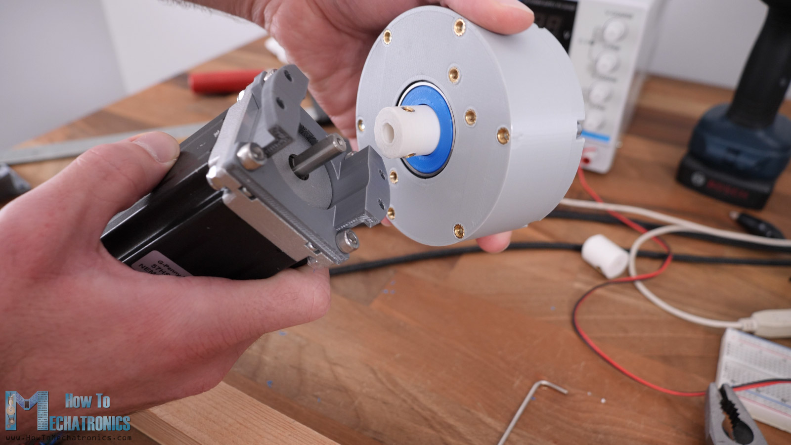
This thing alone has a torque of 3Nm. I initially tried testing it with the same 15cm wooden stick but it simply broke at 80N, or 12Nm of torque.
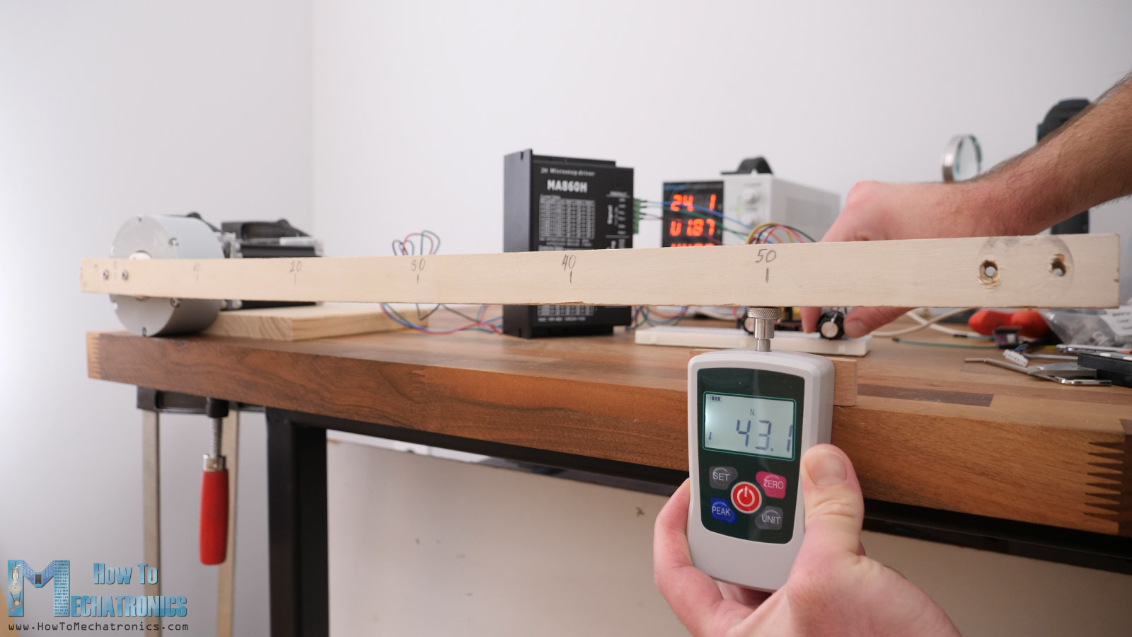
I replaced it with a stronger plywood stick and measured a of force of 30N at a distance 50cm. That’s a torque of 15Nm which is only 5 times higher than the 3Nm the stepper itself is producing.
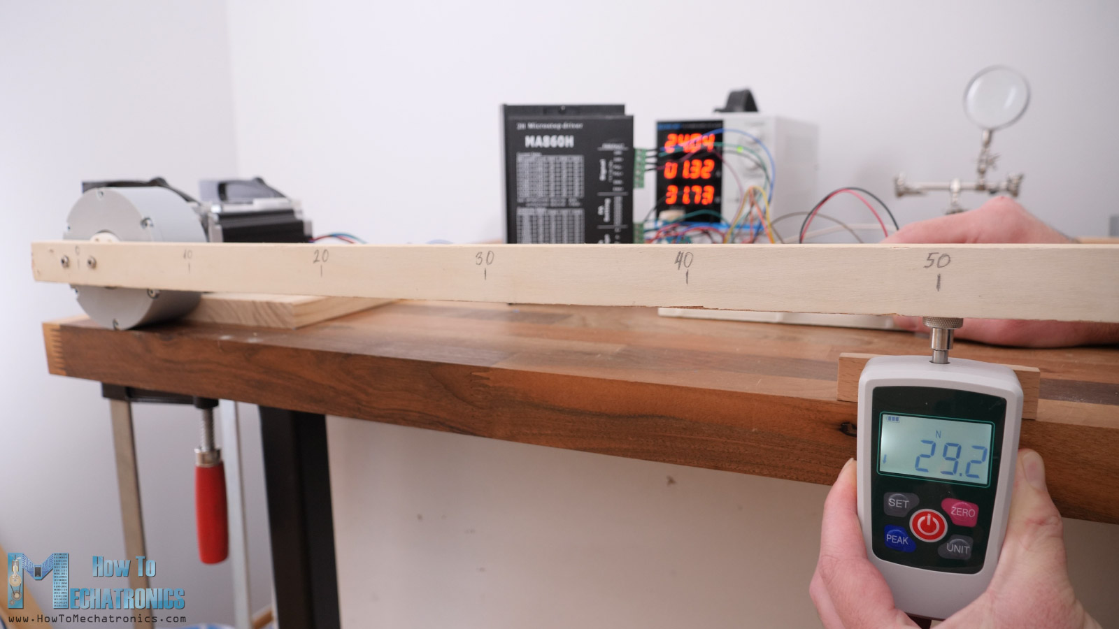
Here it was not the stepper motor that was maxed out, but the cycloidal drive started skipping. A look inside of it revealed that the cycloidal disk broke in the area where they are in contact with the eccentric bearing.
I printed new disks with 4 Wall Lines and increased Infill Density and put it to test again. Now the cycloidal drive reached 43N of force at a distance of 0.5m, or that’s around 4.4kg at a distance of half meter or 21.5Nm of torque.
It started skipping again and a ton of backlash appeared which means there’s another failure in it. A look inside revealed a deformation of the shape of the cycloidal disks.
So that would be the maximum torque this cycloidal drive can handle. Although that’s just 7 times torque increase, I think it’s still impressive as these are really big loads considering it is 3D printed and such a mall gearbox.
On the other hand, the harmonic drive failed right away with the NEMA23 stepper motor. There is simple no way the harmonic drive can handle that amount of torque as the cycloidal drive. The flex spline walls are just too tin and the PLA material too week.
In terms of durability, it’s the same thing. The cycloidal drive can last much longer than the harmonic drive.
Of course, we are talking about 3D printed drives here.
Conclusion
So, what’s my final verdict, what’s better a 3D printed harmonic drive or a 3D printed cycloidal drive?
Well, the answer is the most unpopular one, it depends. I mean, considering the results from these particular drives, I would peak the cycloidal drive. It offers greater torques, it’s more reliable and more durable. Of course, there is also a room for improving the backlash if we make the cycloidal disks even more precise.
On the other hand, the harmonic drive can be definitely better in terms of backlash, but the problem is flex spline durability. I mean, it handled the NEMA17 stepper loads just like the cycloidal drive which was fine. However, in order to improve the durability, we would need a different design of the flex spline, a bigger and longer one, which means that the harmonic drive would lose some points on compactness.
A different 3D printing material would also help. For example, the last flex spline that I made was fine just until the next day when the output started to be even more jerky. I realized that the PLA flex spline had experienced a plastic deformation just by sitting in one position over the night.
Let me know me know what is your experience with harmonic and cycloidal drives in the comments section.
I hope you enjoyed this tutorial and learned something new. Feel free to ask any question in the comments section below.
First of all, I would like to thank you for your excellent work, it has been a great help to us at school, we teach Electronic Engineering in Chihuahua, Mexico.
I downloaded the SLDPRT files for the Harmonic Drive 1-25, instead I got the Cycloidal Drive files, what I mean is that the Cycloidal Drive files are in both links.
Could you please upload the correct SLDPRT files for the Harmonic Drive 1-25?
I really appreciate your help, sincerely
Hi, thanks! Sorry for the inconvenience. I have updated the download link for the Harmonic Drive.