In tutorial I will show you how I built a super cool radio controlled tracked vehicle, or a robot platform or a tank, you name it. I designed this thing from scratch to be fully 3D printable so you can easily print everything and build one on your own.
You can watch the following video or read the written tutorial below.
Overview
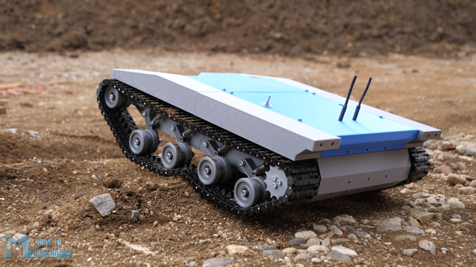
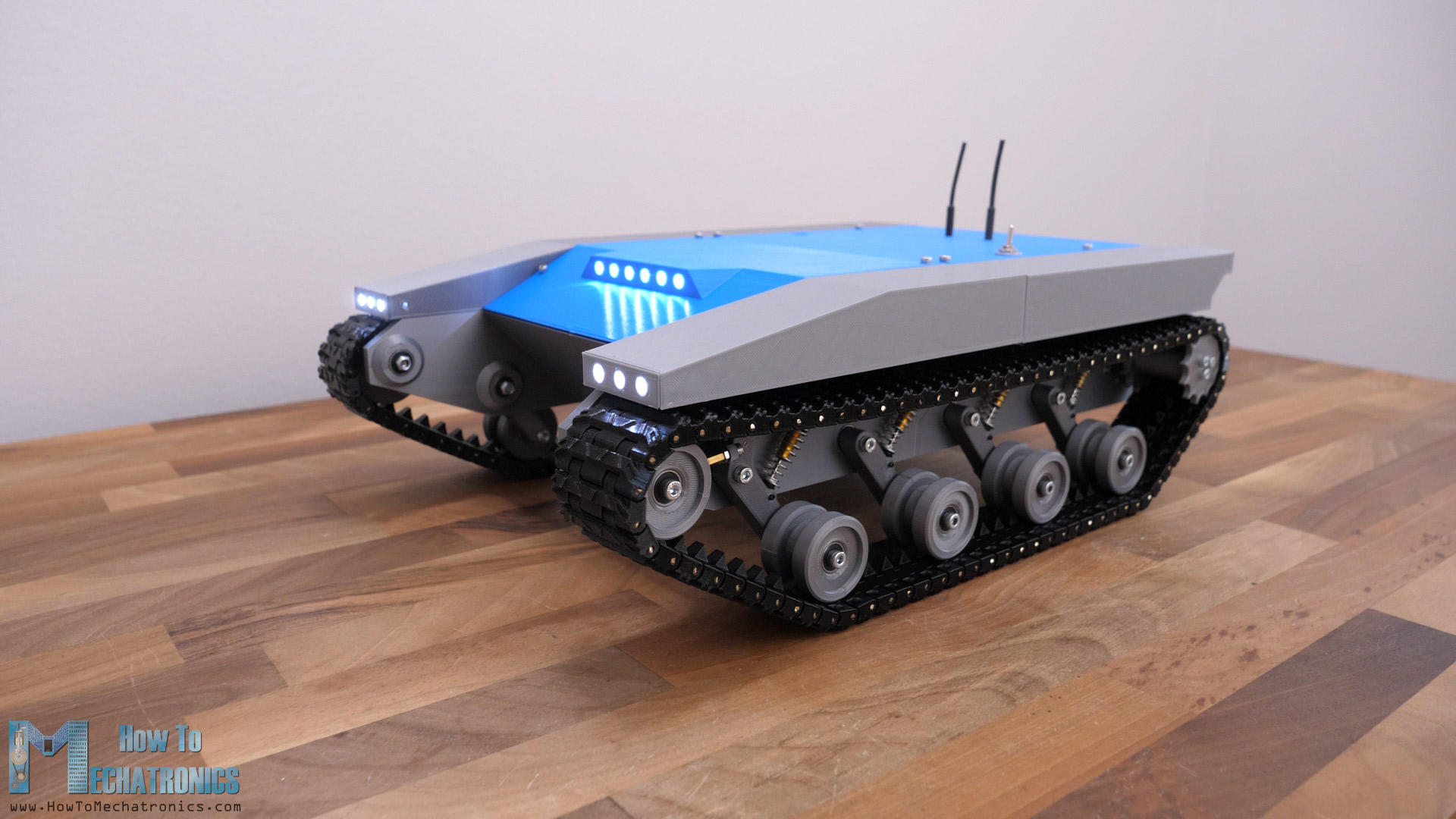
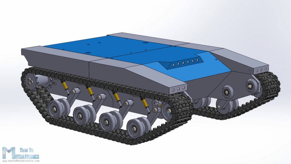
My goal for this project was to make a versatile platform that can traverse many types of terrains and can be used for various applications. The best bet for that was to use a continuous tracks system. The tracks distribute the weight of the vehicle on a larger surface area which provides excellent grip and lowers the odds of getting stuck in soft ground, mud or snow.
The robot platform drives quite well in mud and it’s a pity I didn’t have a chance to test it on snow. I hope I will in some of my future videos where I plan install a robotic arm or a turret. With a robotic arm on top of the platform we can do various tasks like grab and move something, or we can put a camera to it and use it for visual inspection and so on. Or for example, we can make a turret that can fire NERF darts and in combination with the simple but cool LED lighting that I already installed on this platform, we can have quite some fun playing with it.
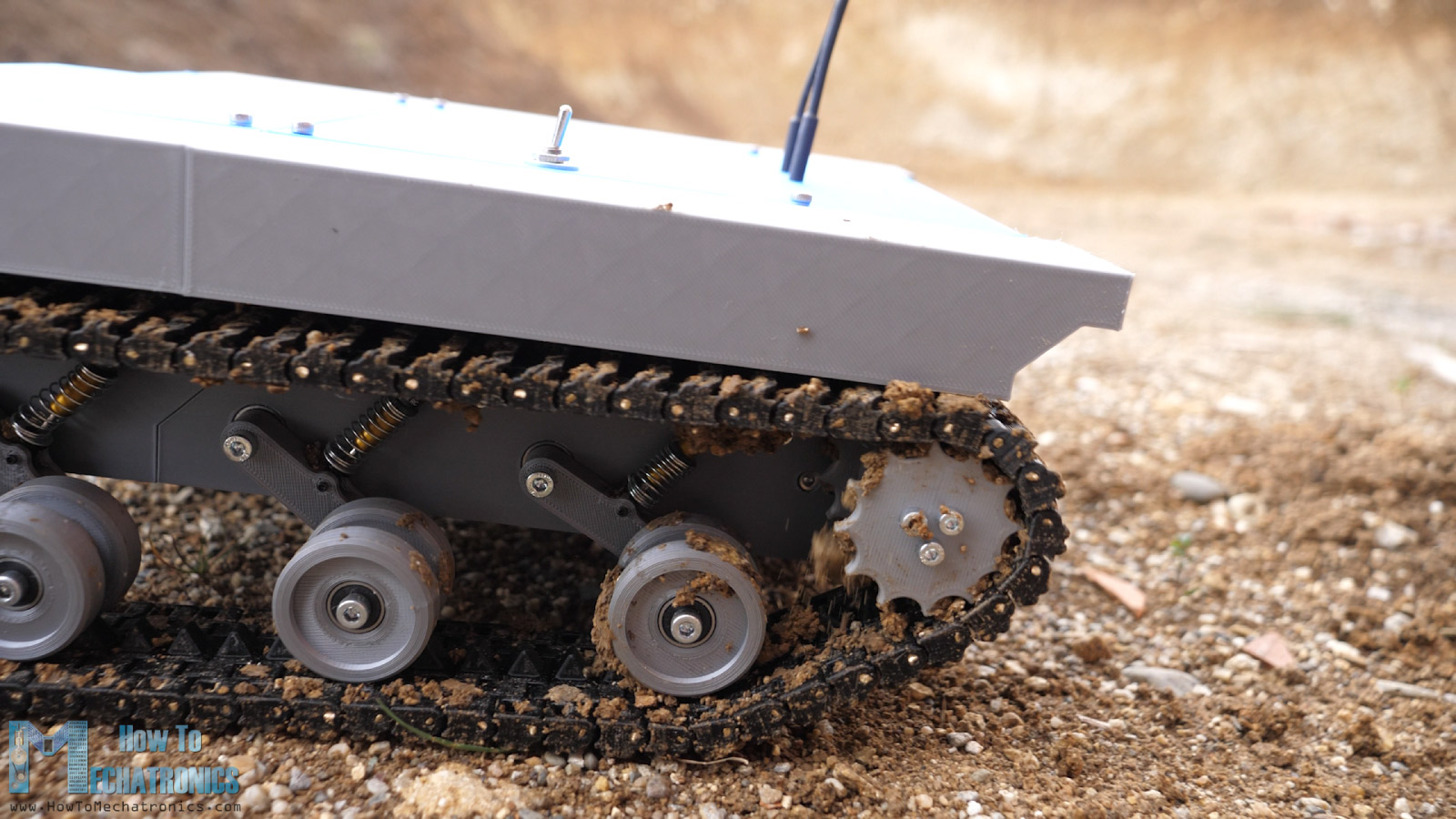
As for the suspension, I employed a Christie suspension system that’s been used in tanks for many years. With this setup each roadwheel has an individual suspension or a spring and a shock absorber.
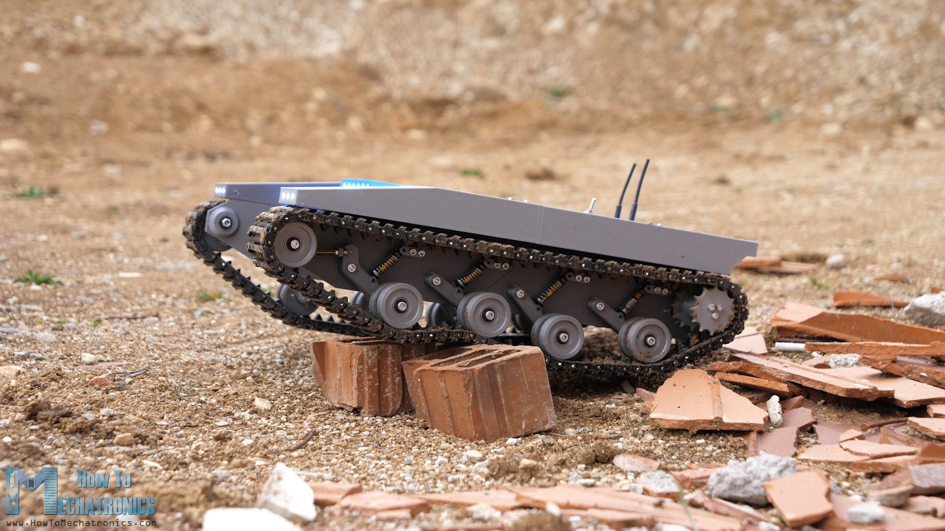
That allows the vehicle to run smoothly on uneven terrain and climb obstacles while maintaining good contact surface between the tracks and the terrain.
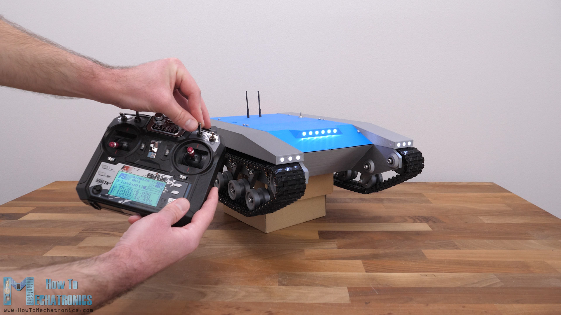
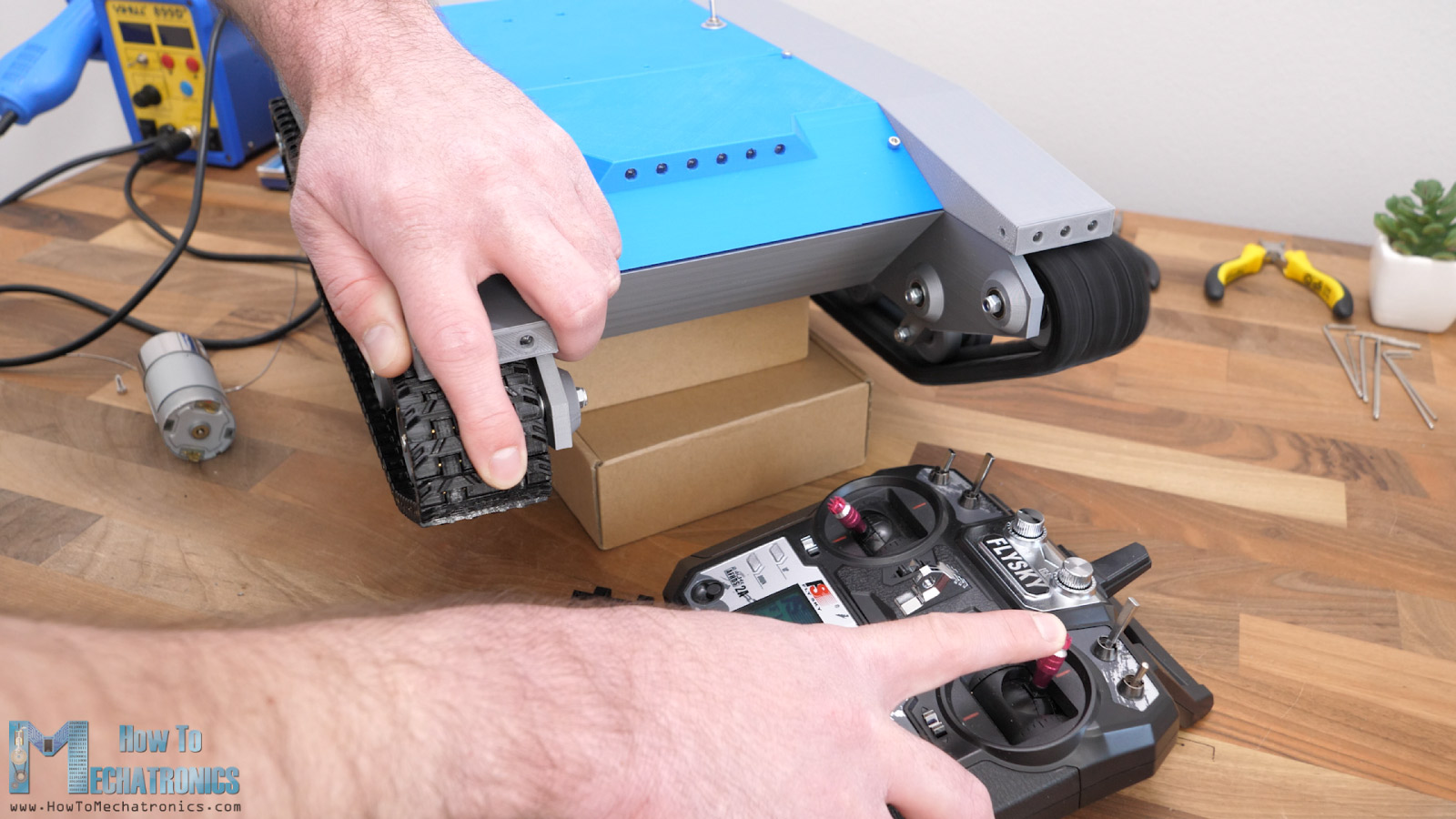
For controlling the 3D printed tank, I’m using a cheap commercial RC Transmitter which sends commands to the platform.
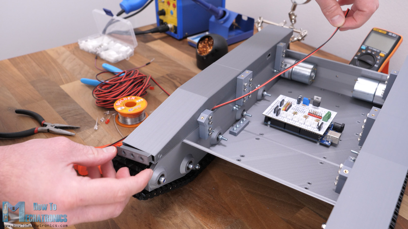
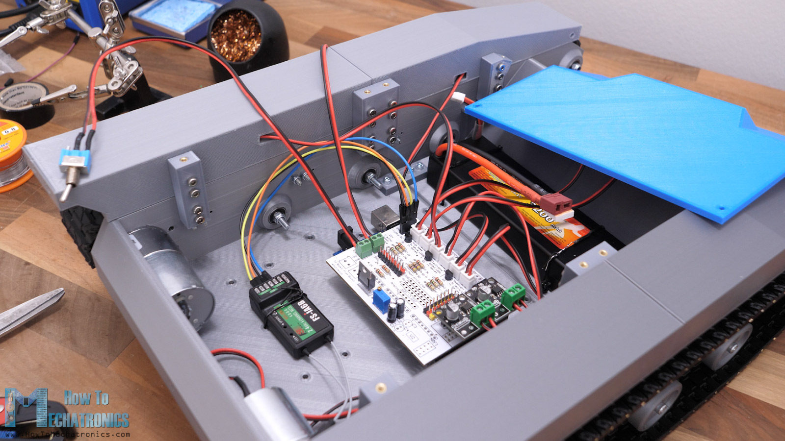
On the platform I have a suitable RC receiver which receives the commands and sends them to a microcontroller. The brain of this platform is an Atmega2560 microcontroller-based board and for easily connecting everything together I made a custom PCB which can be simply attached on top of the board.
Nevertheless, now buckle up as I will walk you through the entire process of building this robot platform, starting from the design, 3D printing, assembling, connecting the electronics components and programing the microcontroller.
Design the Robot Platform
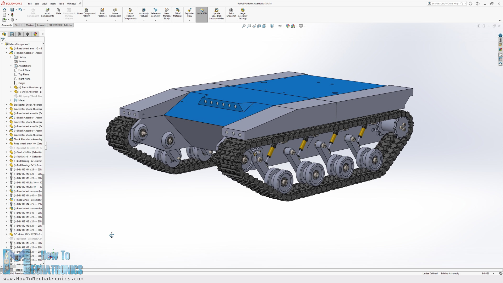
I designed this robot platform using SOLIDWORKS, which is also the sponsor of this video.
— Sponsored section —
“It’s worth noting here that these industry-leading and professional-grade design tools are now available to all makers at a remarkably low price of only $99 per year or $9.99 per month. That’s right, 3DEXPERIENCE SOLIDWORKS for Makers is great for anyone learning the trade, making DIY projects, and more.
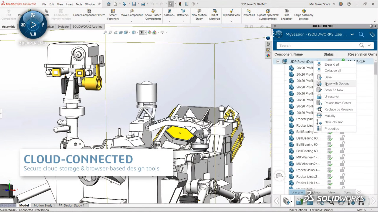
This offer includes 3DEXPERIENCE SOLIDWORKS Professional, the most in-demand CAD tool within the offer and runs locally on your PC. You can store files locally or in the cloud with the 3DEXPERIENCE platform.
“xDesign”, browser-based CAD, you can use it with 3DEXPERIENCE SOLIDWORKS, or on its own. It’s great for modeling anywhere, anytime, and on any device.
“xShape”, browser-based freeform CAD that’s easy to use for surface modeling on any device.
“Visualize Connected”, easily create photo-quality images, animations, interactive web content and more to impress your audience.
“NC Shop Floor Programmer”, CAM for intelligent machining strategies for 3-axis milling and wire EDM in an easy use package.
Click the link below, and you’ll get a special 20% off – so you can start making with the best today! Big thanks to SOLIDWORKS for sponsoring and supporting education content like this. ”
Buy Now: http://www.solidworks.com/makers20
Learn more: https://discover.solidworks.com/3dexperience-solidworks-makers
— Back to topic —
Let me explain how I came up with robot platform design. The first input parameters for the design were these RC shock absorbers that I had and their dimensions.
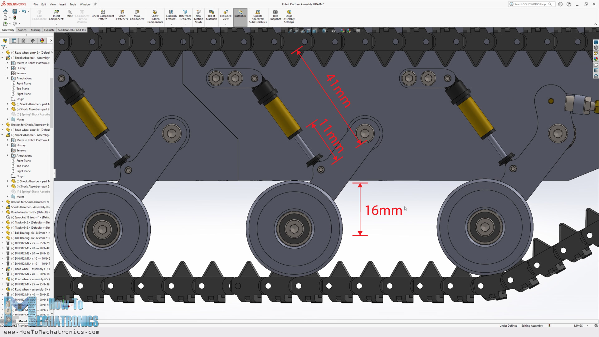
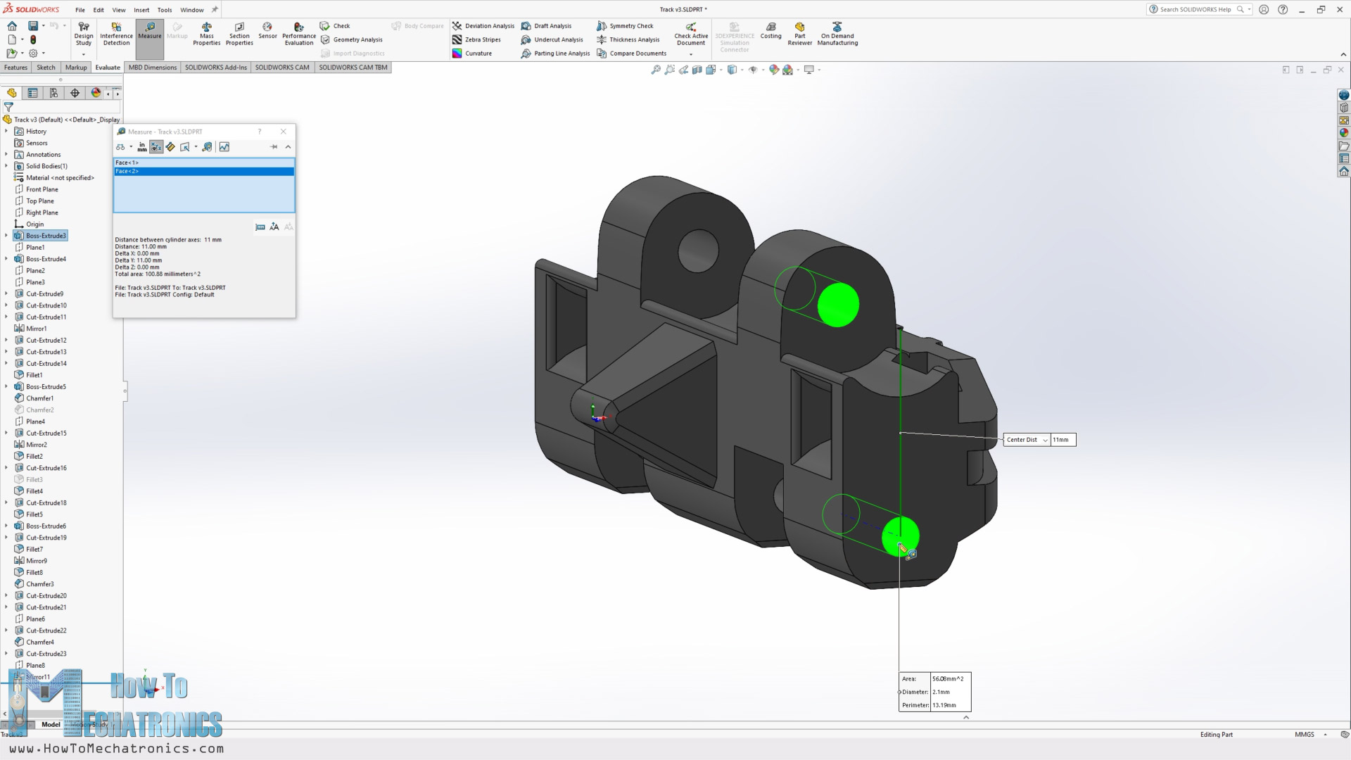
I had 8 of them which meant that there will be 4 roadwheels on each side, and they were 41mm in length when extended with 11mm travel. According to these dimensions, I wanted to get a bit greater vertical travel distance for the roadwheels, so I came up with this mechanism that got me a vertical travel of 16mm for the roadwheels.
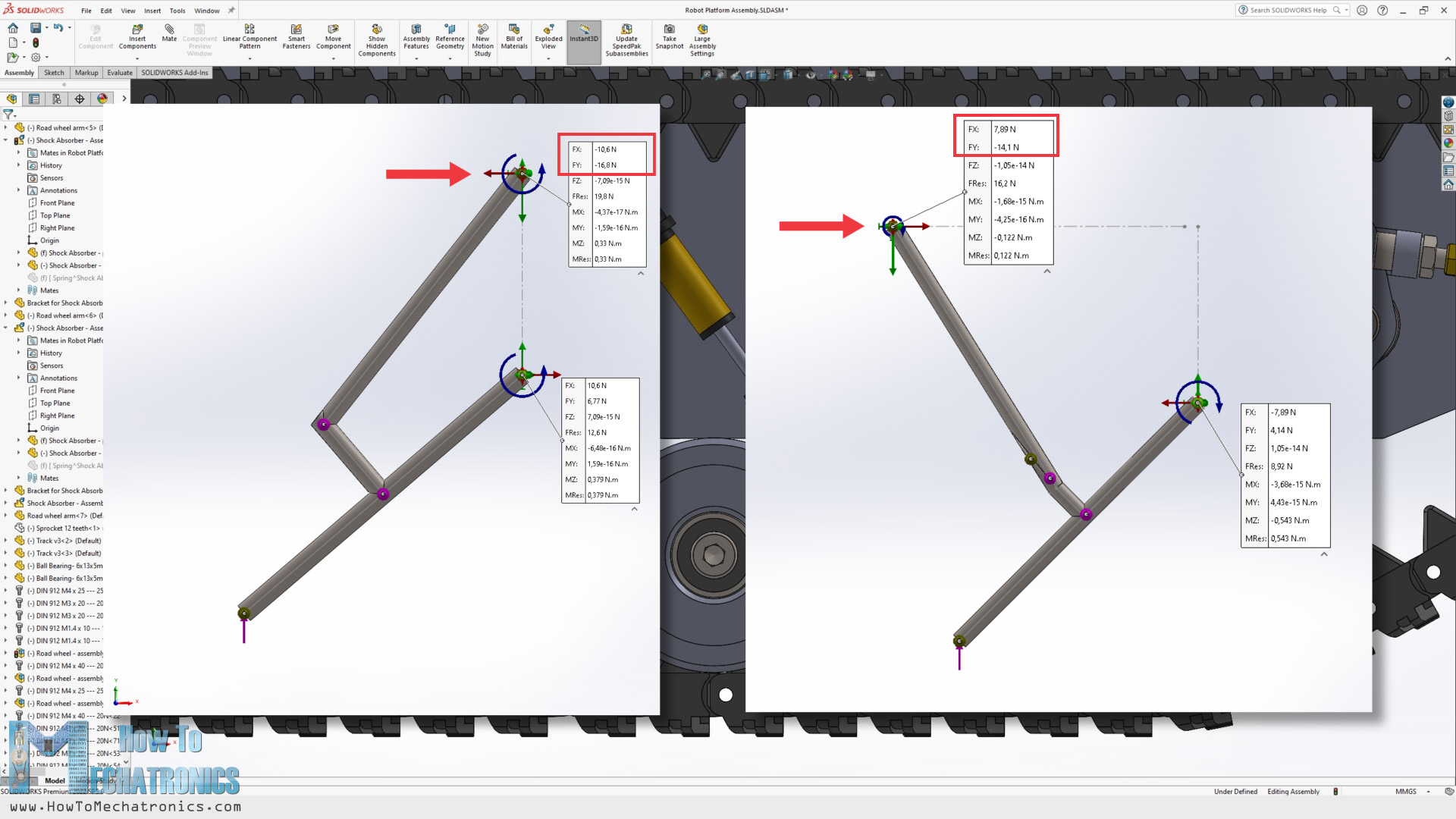
I mean, I can get even greater travel distance if I move the joint of the shock absorber and roadwheel link closer to the pivoting point of the roadwheel link, but then I would lose the force of the spring, or I would need a stronger spring to hold the platform properly.
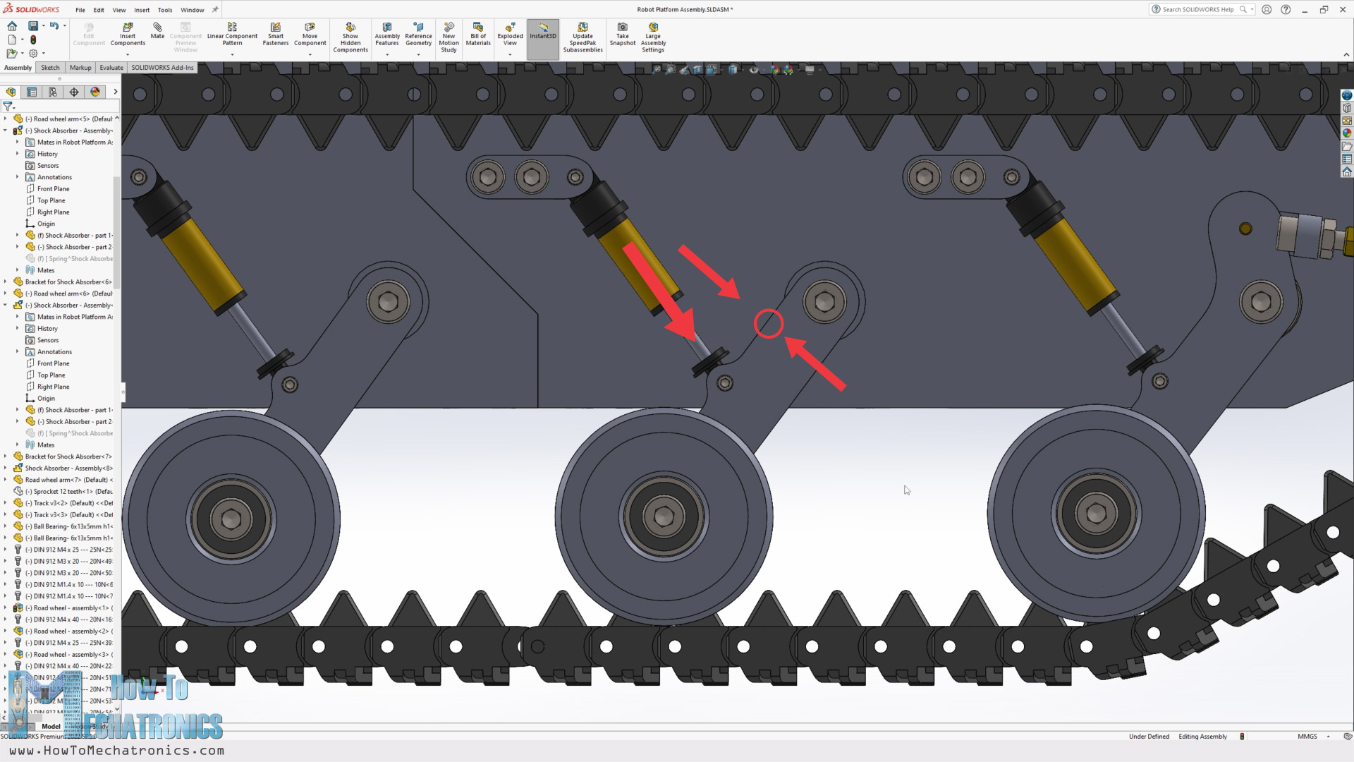
I did some simple simulations with SOLIDWORKS to check out the reaction forces to the springs with different mechanisms and so I chose this mechanism which also provides good overall compactness.
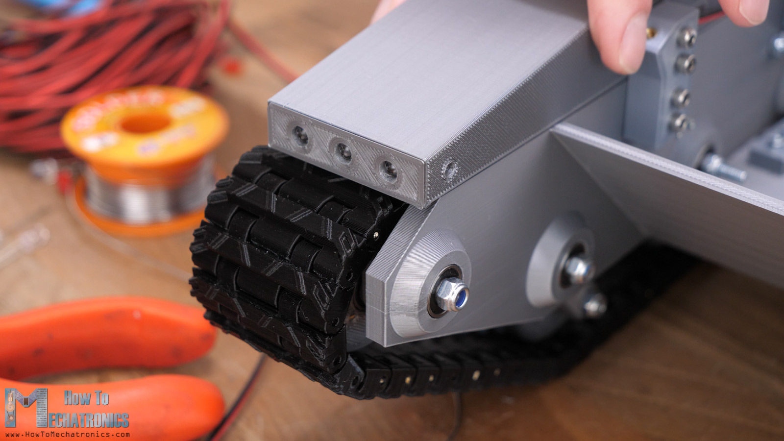
If we take a closer look at the front roadwheel, we can see how it’s connected with the idler wheel which provides dynamic tension of the track. When the roadwheel goes up, the track circumferences get smaller and so the tension loosens.
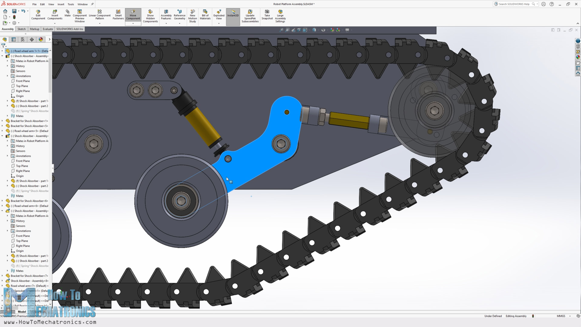
With this connection here, when that happens, the idler wheel is pushed forward to tension the track. With this connection we can also tension the track statically, by adjusting this bolt and distance nut.
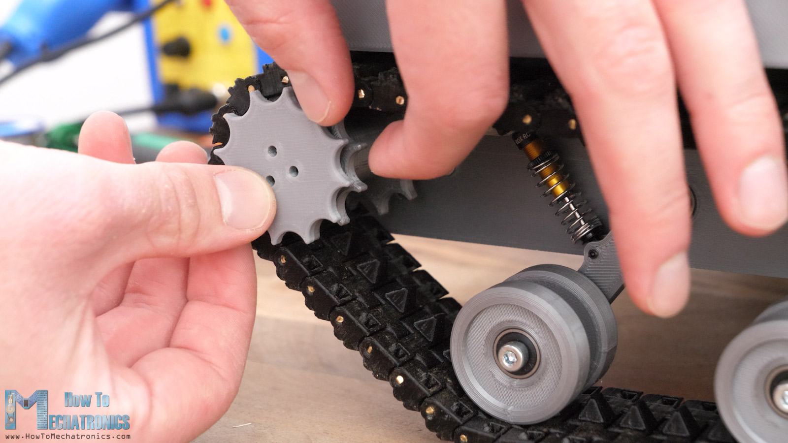
At the back side, we have the sprocket which is composed of three parts. It has the shaft coupler and left and right section of the sprocket connected all together with three M3 bolts.
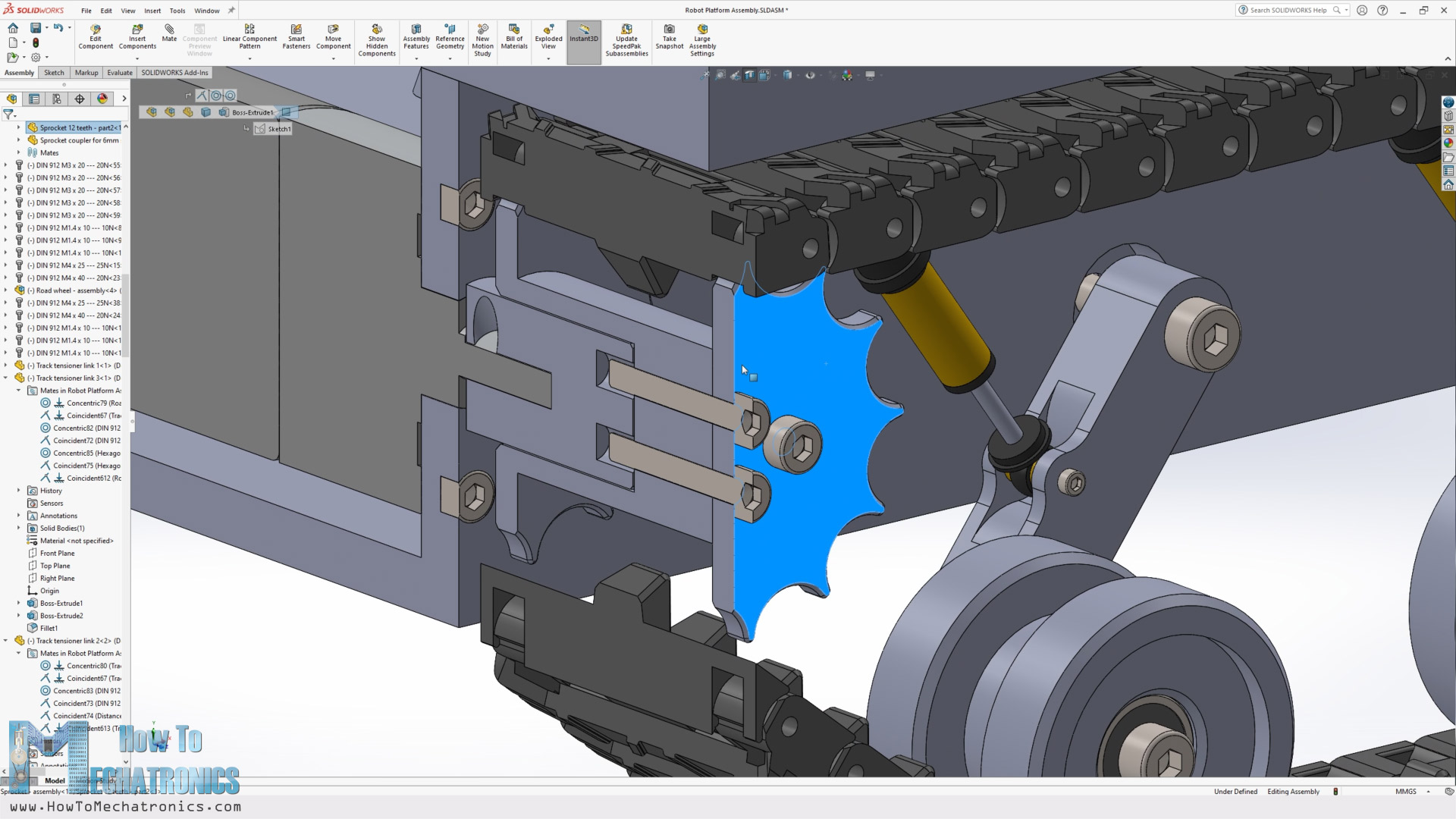
The key dimension here on the sprocket is the pitch because it must match the pitch of the track. The pitch is 11mm here and I chose the sprocket to have 12 teeth which gave me a pitch diameter of the sprocket of around 42mm.
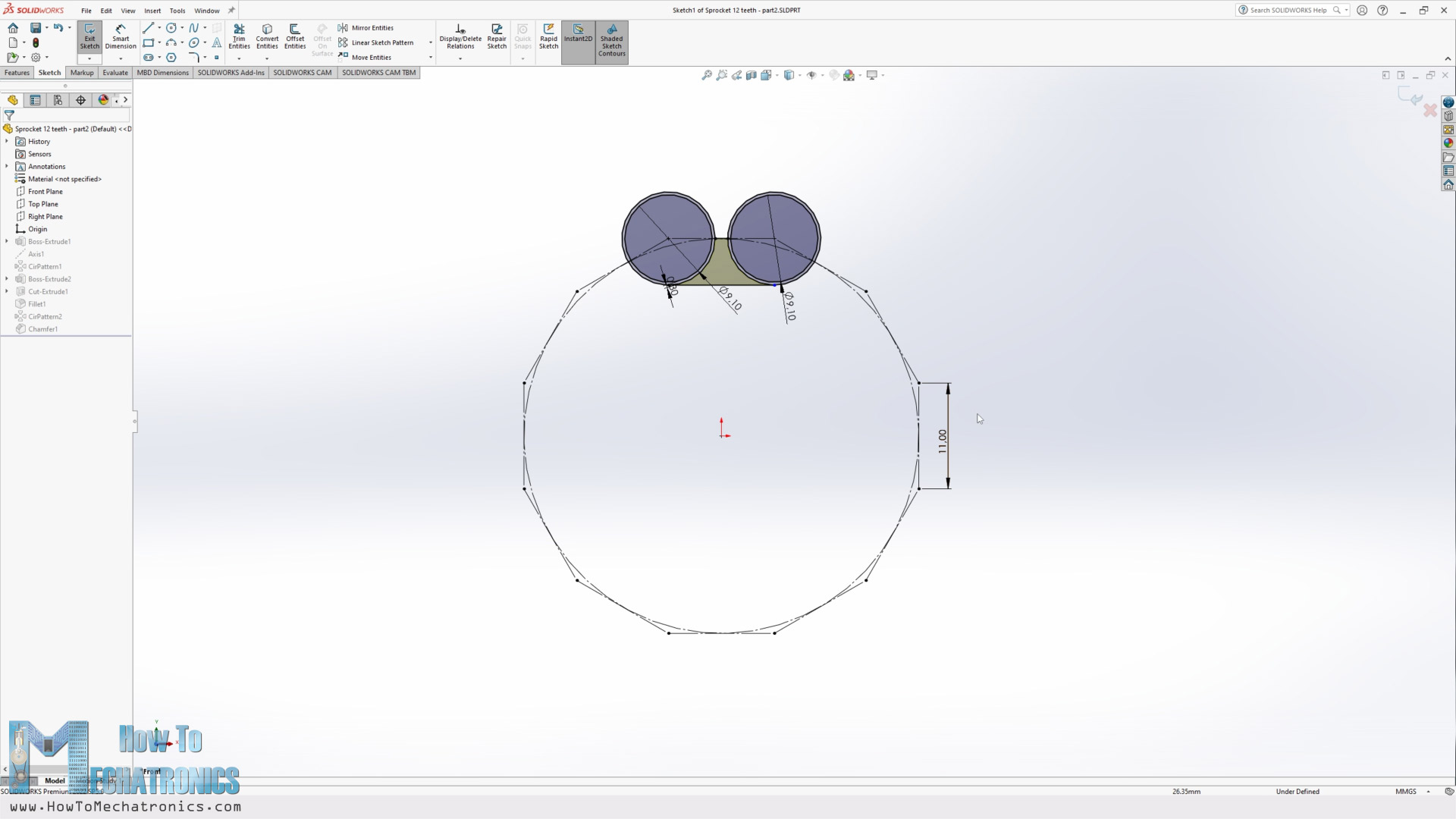
The 11mm pitch was actually defined by the design of the track link. My goal for the track link was to be as compact as possible and to connectable with the next link with just one additional part or pin, while being strong enough to be made with a 3D printer.
On top of that, when 3D printing, I wanted to avoid any use of support material for the part, which I actually managed to achieve with this design.
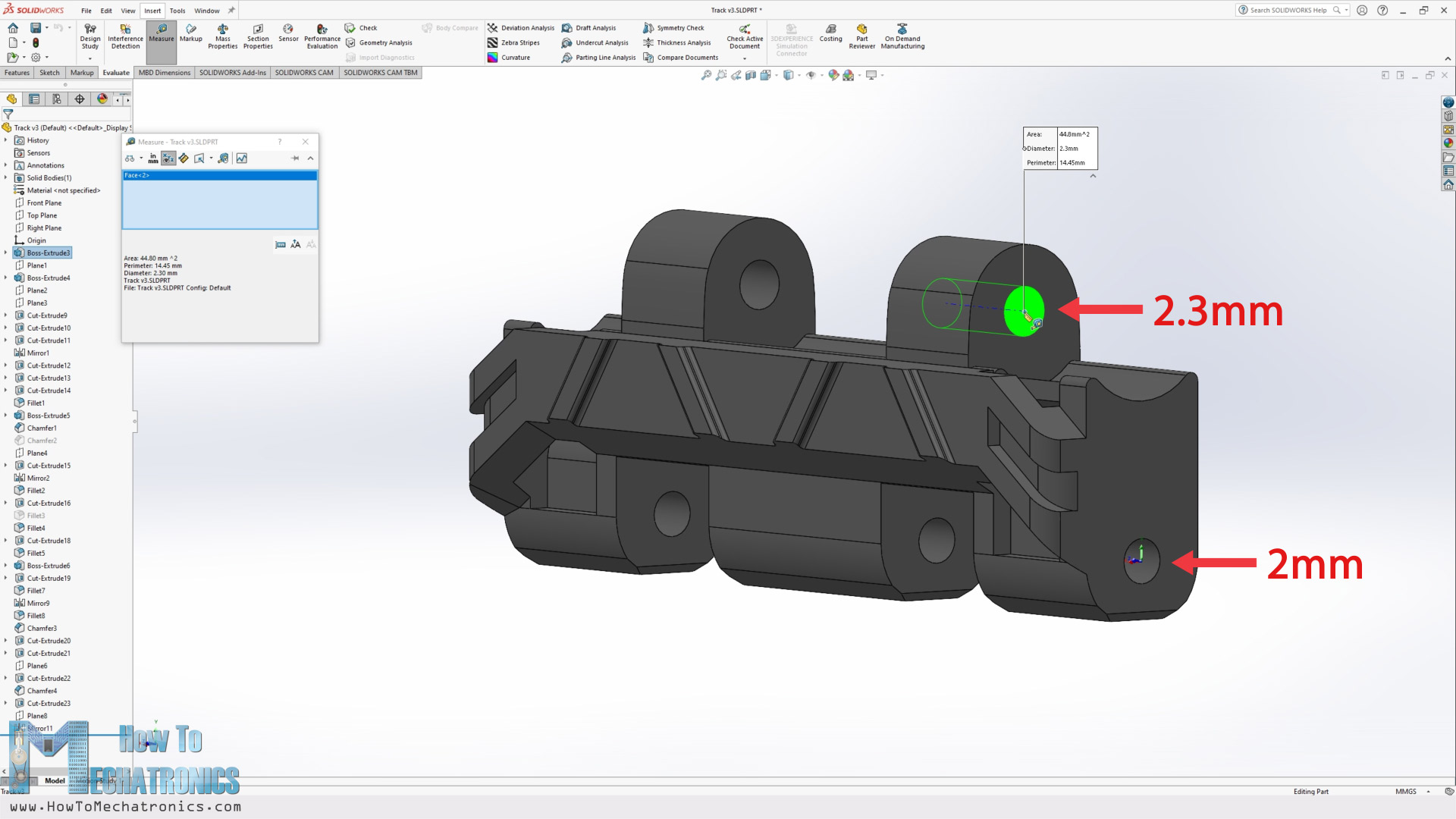
For connecting the track links to each other, I planned to use pins with 2mm diameter, so I dimensioned one side to be 2mm, to get tight fit, and the other side 2.3mm, to get loose fit so that the track links can rotate freely.
The sprocket teeth go into this opening here where the pins of the track link are formed with 8.8mm diameter, whereas the sprocket diameter is 9.1mm in order to have a loose fit to work properly.
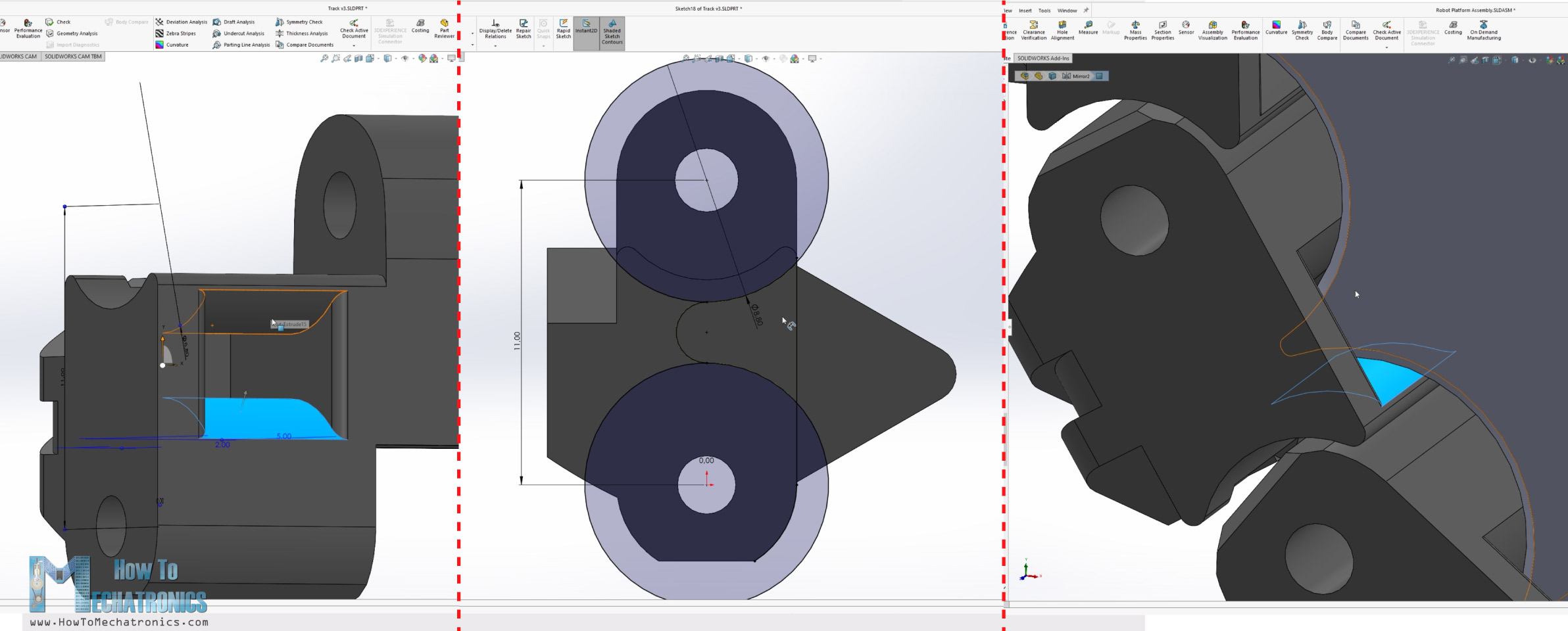
Once I had all these parts defined, I drew a sketch in the assembly environment, a closed contour around the sprocket, the idler wheel and the roadwheels.
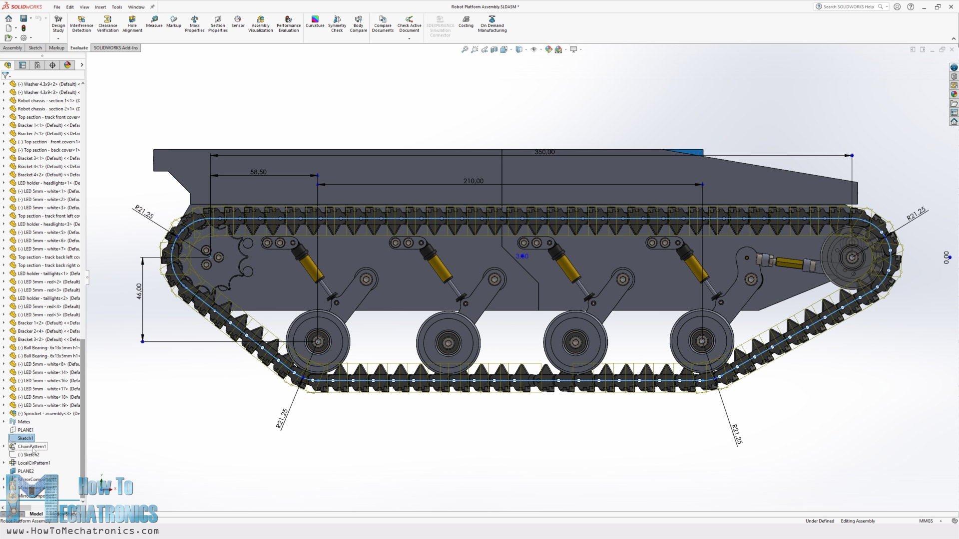
Then I used this sketch with the SOLIDWORKS Chain Component Pattern feature to generate all track links along that contour.
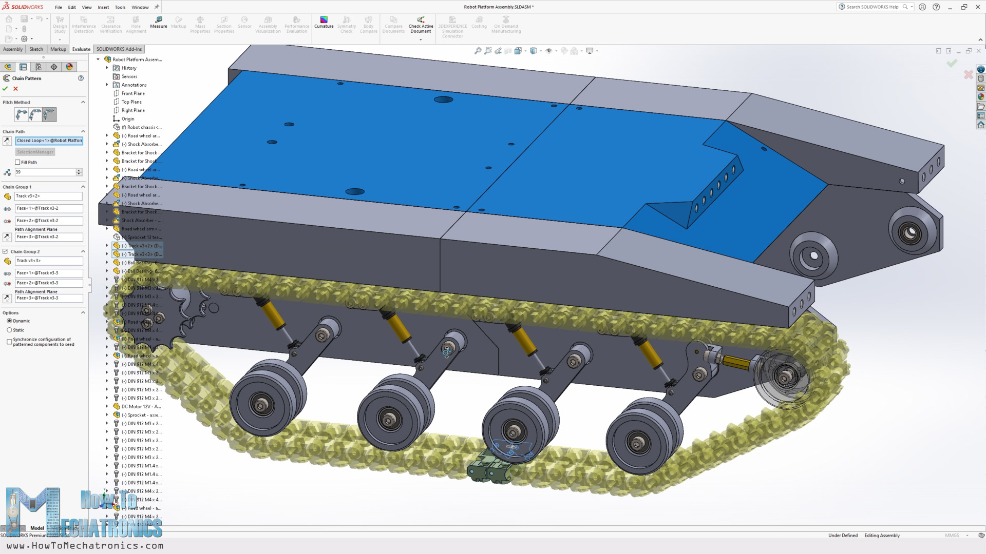
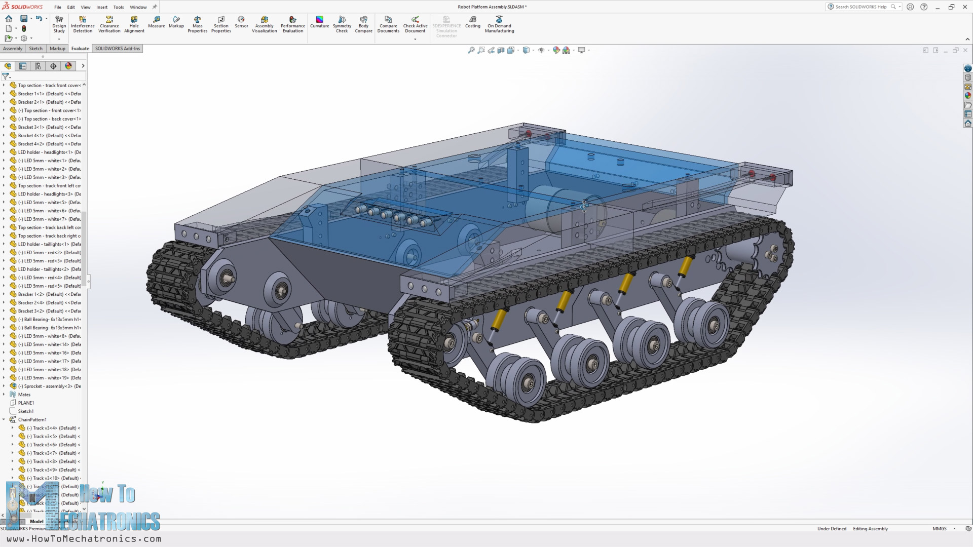
I designed the rest of the robot platform, the base where everything is connected, the sides that accommodate some LEDs and the top covers, in what I thought is a modern and cool looking style. As the overall dimension of the platform is bigger than most 3D printers, around 400mm by 300mm, I divided all the parts into two sections, so we can print them on almost any 3D printer. They are connected together with some brackets and M3 bolts.
For assembling the whole robot platform, we need various M3 and M4 bolts and nuts, as well as some threaded inserts and bearings. You can find a complete list of all the components needed for this project below in the assembly section.
3D Model and STL Download Files
You can get the 3D model of this RC tank/ robot platform , as well as the STL files for 3D Printing from Cults3D.
3D Printing
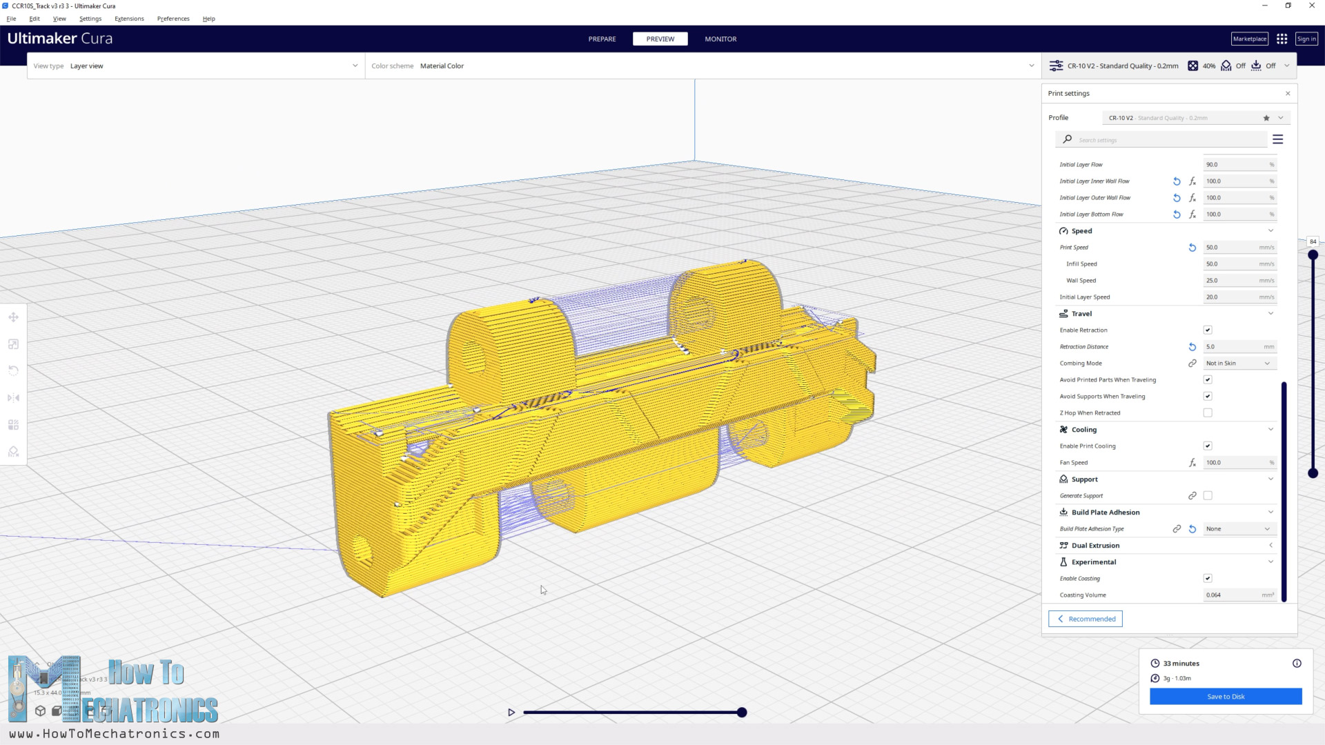
When 3D printing, in order to get dimensionally accurate 3D printed parts, we should use the Horizontal Expansion and Hole Horizontal Expansion settings in our slicing software. If we leave these settings by default, the prints outer dimensions as well as the holes are usually smaller than the original model.
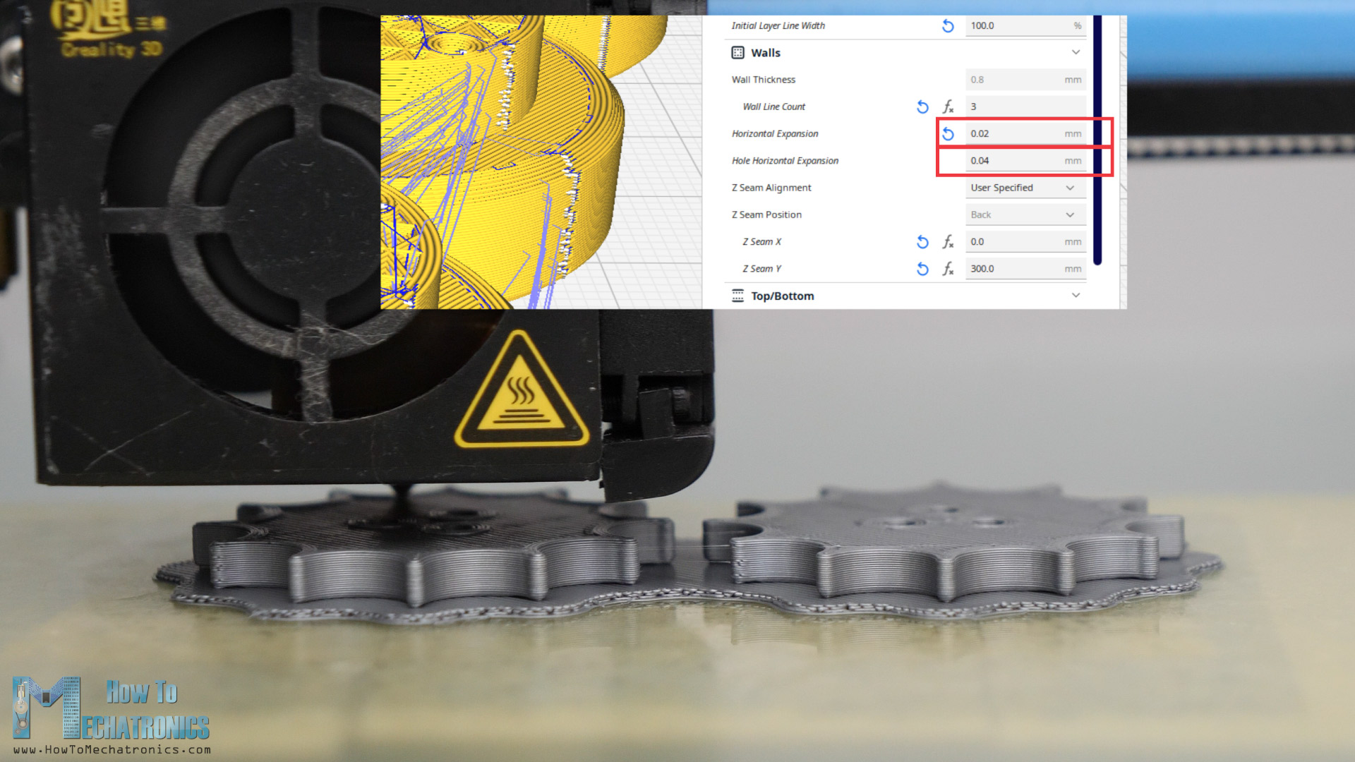
I set the Horizontal Expansion to 0.02mm and the Hole Horizontal Expansion to 0.04mm. Of course, you should do some test prints to see what values will give you the best results on your 3D Printer. We need accurate dimensions of the parts to easily assemble them each other and with the other components like the bearings and the bolts.
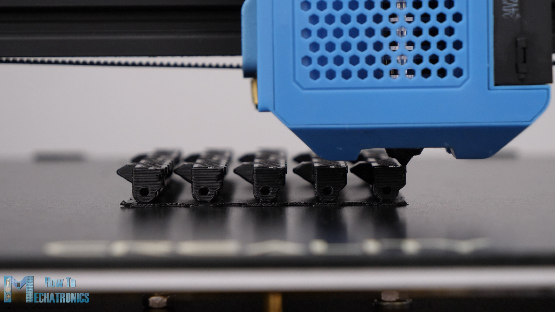
When 3D printing the track links, I used a raft as build plate adhesion, because their contact surface with the bed plate is a bit small and might not stick well if the bed adhesion on your printer is not that good. Especially when printing larger batches, it’s safer to use a raft.
Assembling the 3D Printed Tank – Tracked Robot Platform
Ok, so here I have all 3D printed parts for the robot platform. To be honest it took quite some time to print everything.
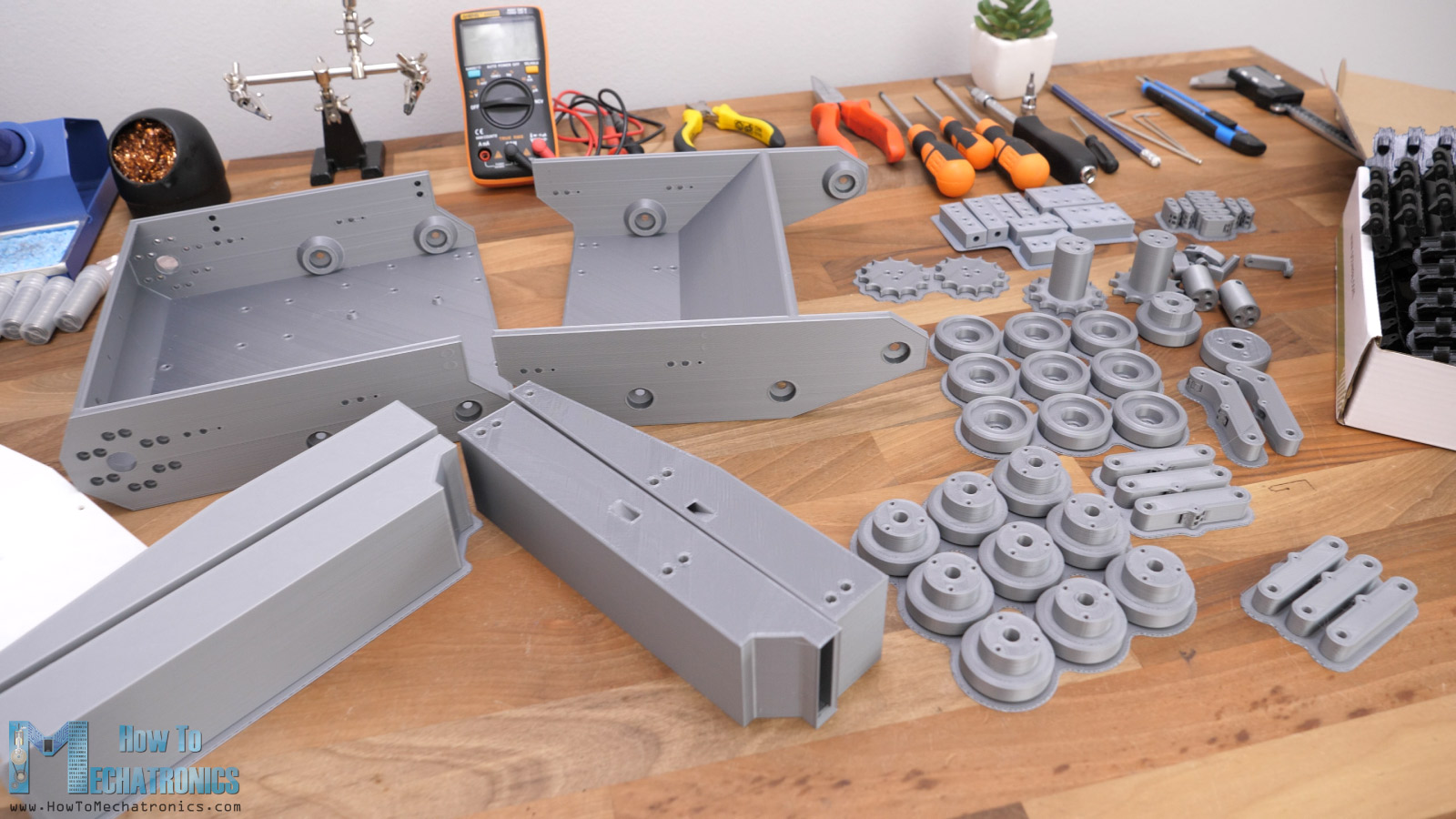
For example, each of the base sections took around 22 hours to print, and all 156 track links took around 96 hours to print. Approximately we need 200 hours to print everything. Luckily, I had two 3D printers, so it took me around 100 hours.
Parts list
Here’s a list of components needed for assembling this 3D Printed tank – robot platform project. The list for the electronics components can be found below in the circuit diagram section of the article.
- 8x RC Shock absorbers …………………………………….. Amazon / AliExpress
- 8x Springs ……………………………………………………………. Amazon / AliExpress
- 40x Ball bearings 624 – 4x13x5mm ………………… Amazon / AliExpress
- M3 Threaded inserts ………………………………………….. Amazon / AliExpress
- M3 and M4 bolts and nuts ……………………………. Amazon / AliExpress
Bolts:
M4x40mm – 8pcs; M4x35mm – 2pcs; M4x30mm – 8pcs; M4x25mm – 2pcs; M3x25mm – 16pcs; M3x20mm – 8pcs; M3x16mm – 10pcs; M3x12/14mm – 32pcs; M3x10mm – 8pcs; M3x8mm – 14pcs
Nuts:
M4 – 25pcs; M3 – 30pcs
Washers:
M4 – 30pcs
Disclosure: These are affiliate links. As an Amazon Associate I earn from qualifying purchases.
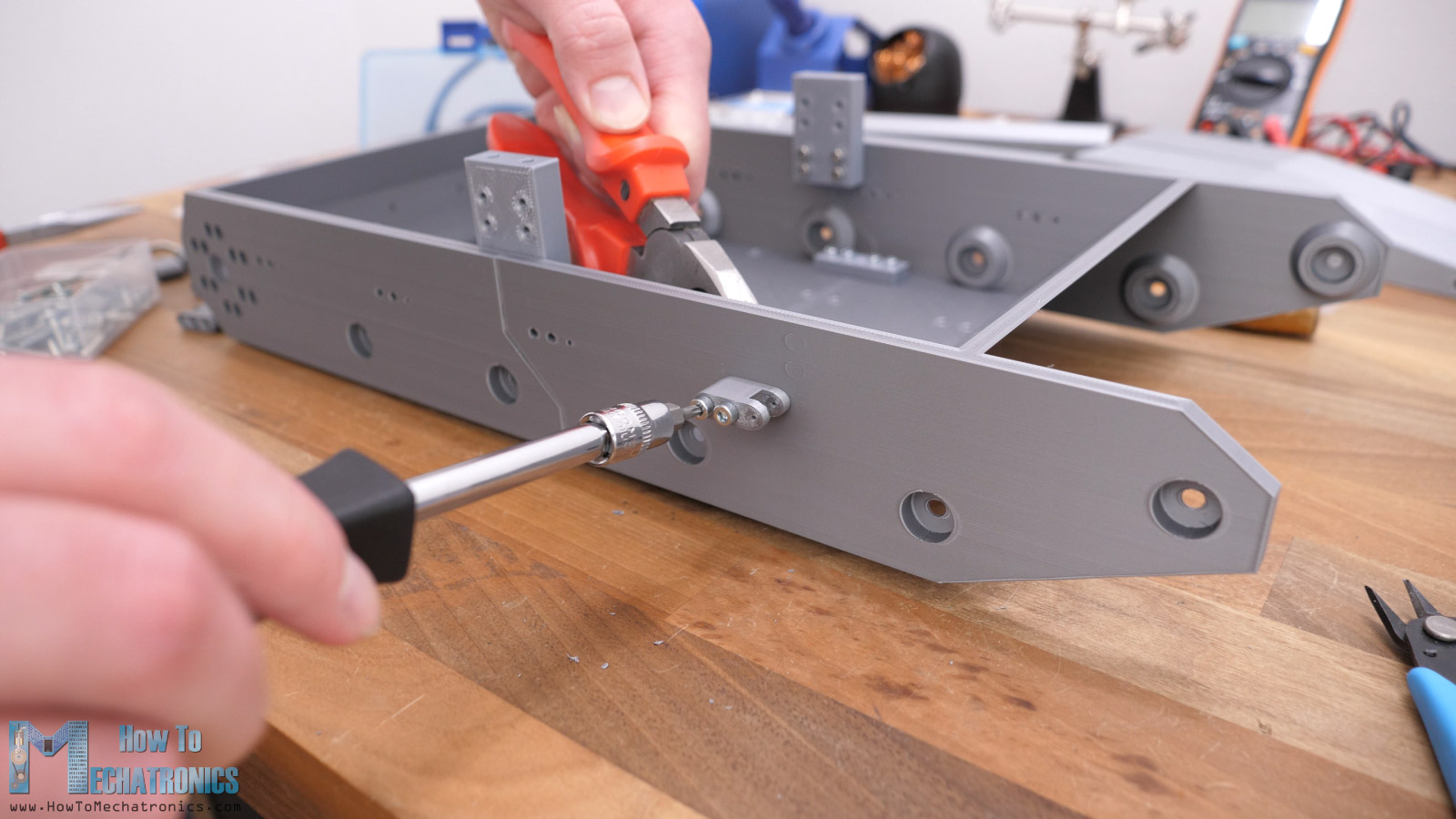
I started with assembling the base. Like I said, it’s composed of two sections that will connect to each other using some brackets and M3 bolts and nuts.
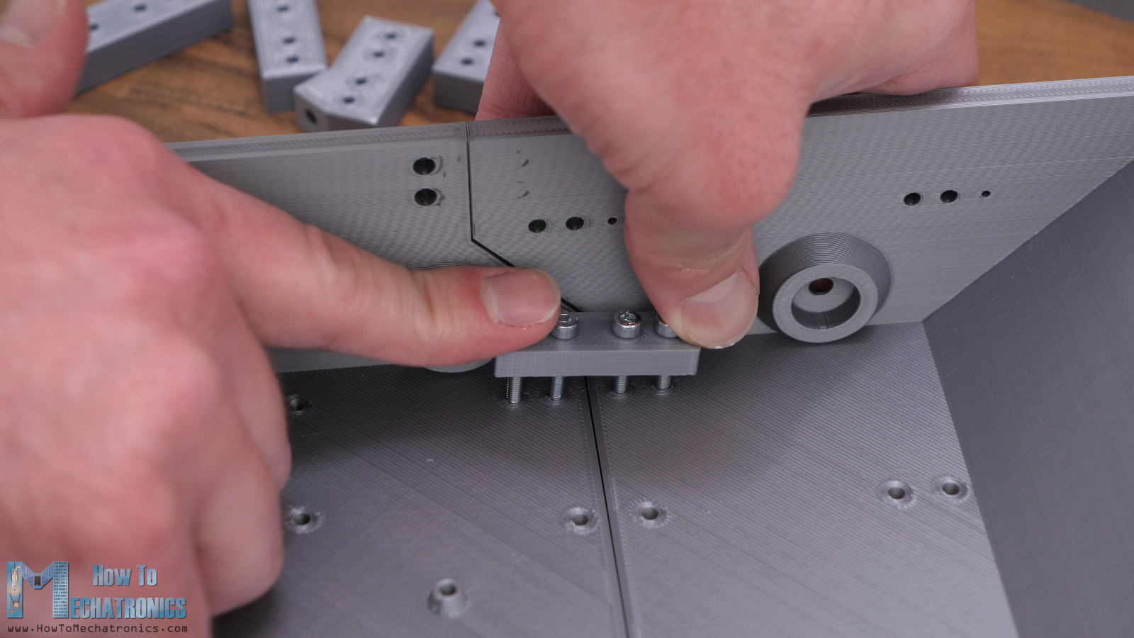
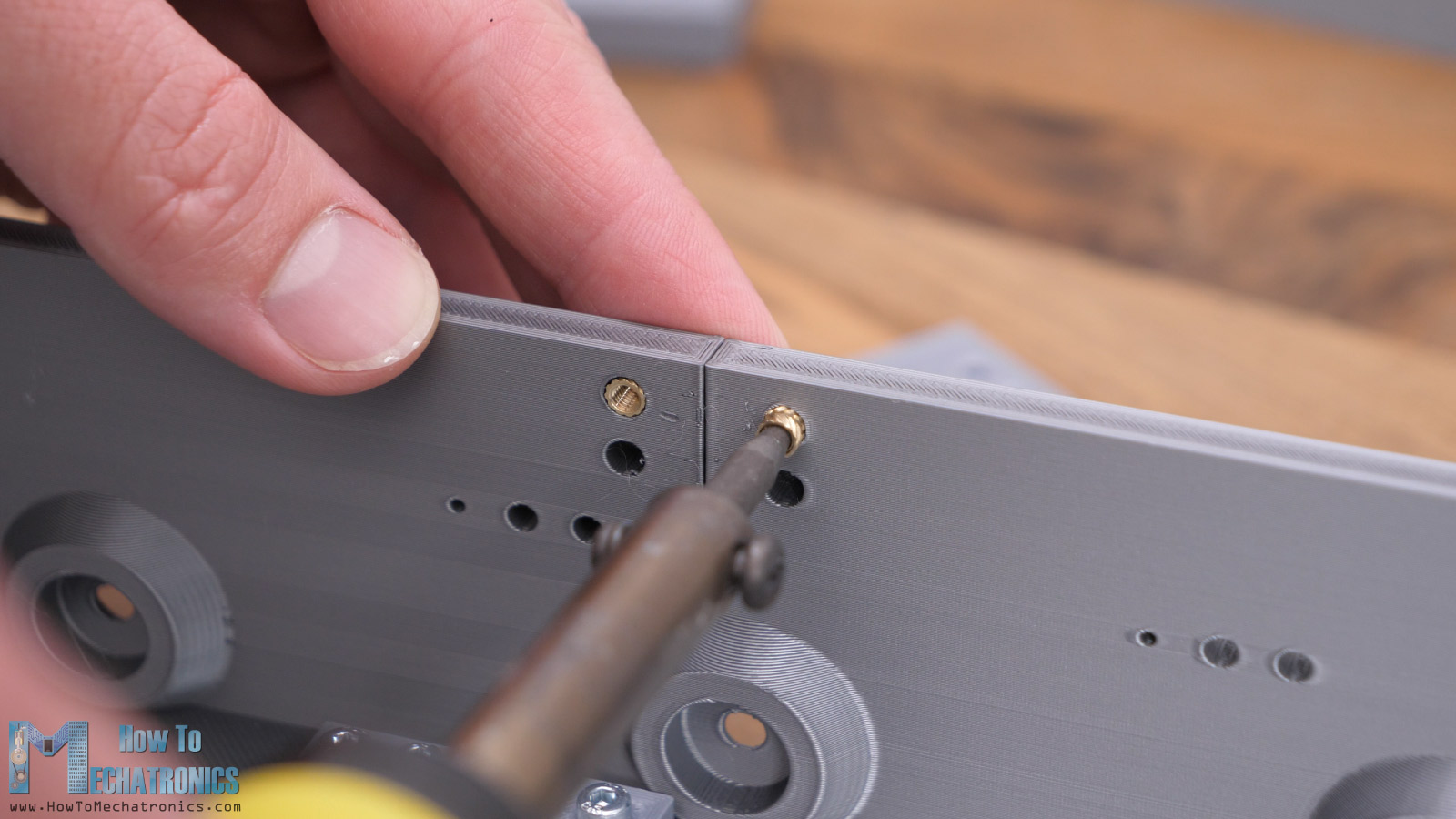
For securing the side brackets, I am using M3, 5mm long threaded inserts that go into the sidewall of the base. In this way, the outside of the wall will be clean with no bolts and nuts so that the tracks can run nearby.
Then, I secured the brackets for attaching the shock absorbers in place using some M3 bolts.
Next, I’m installing the bearings where the roadwheels arm will pivot. The bearings have 13mm outer and 4mm inner diameter and we need two of them for each roadwheel.
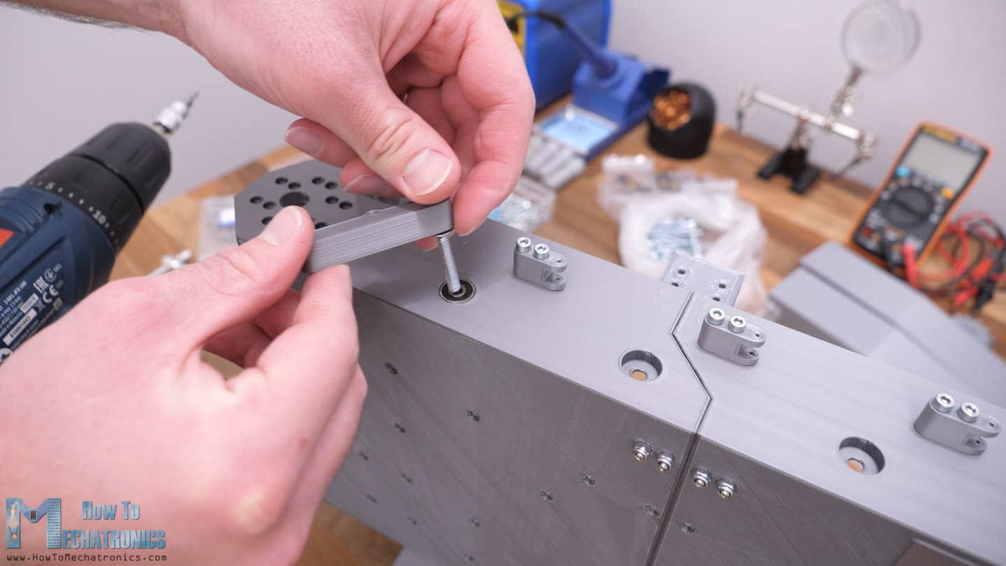
As a pin I’m using an M4 bolt with 30mm length. We need to place a washer between the bearing and the arm and secure them in place from the inside with a self-locking nut. We should be careful how much we tighten this joint, not too tight, but not too loose either.
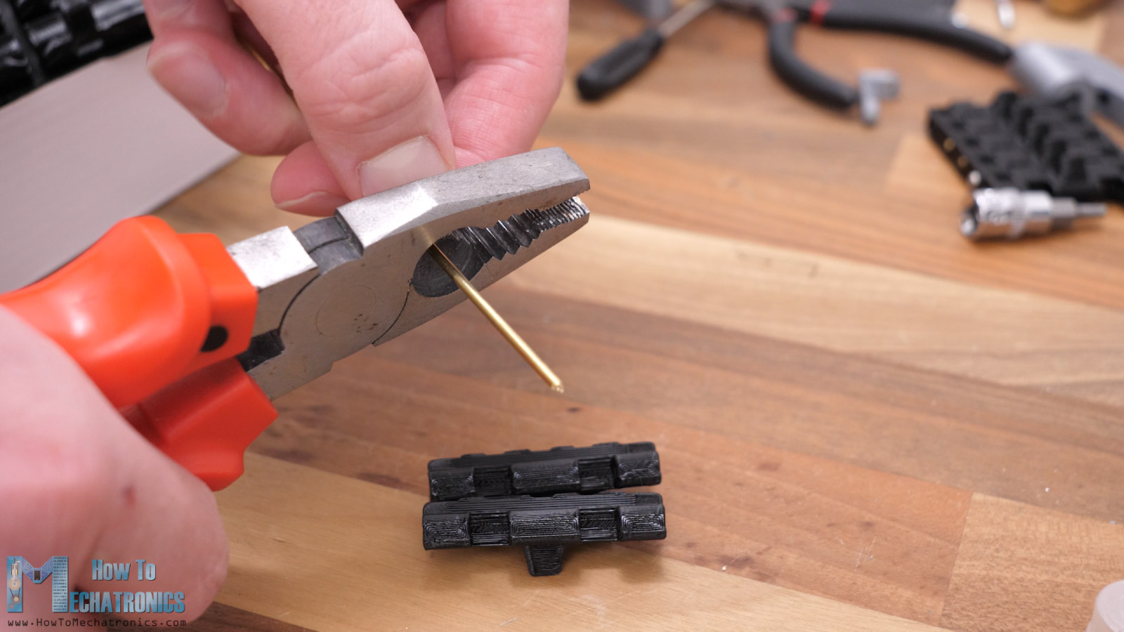
Next, we can install the shock absorber. We secure it in place using the M1.4 bolt that comes with its package.
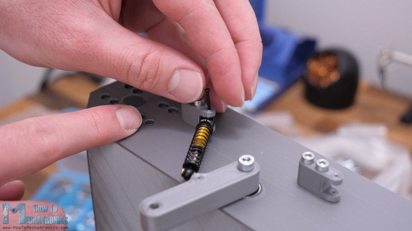
I didn’t have that small screwdriver, so I used pliers for fastening the bolt. So far, it seems that the mechanism works perfectly.
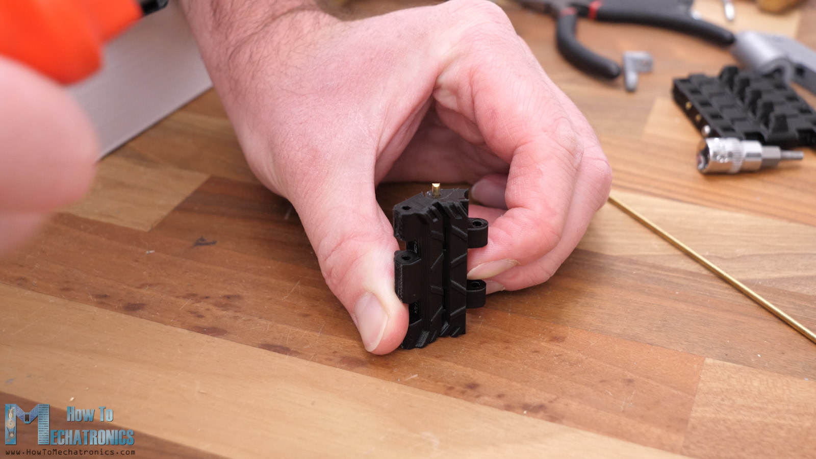
Next, we can install the roadwheel at the bottom end of the arm. The roadwheel is made of two sections in order to avoid printing with support material. Maybe it could be printed as a single part, but I didn’t try how it will come out.
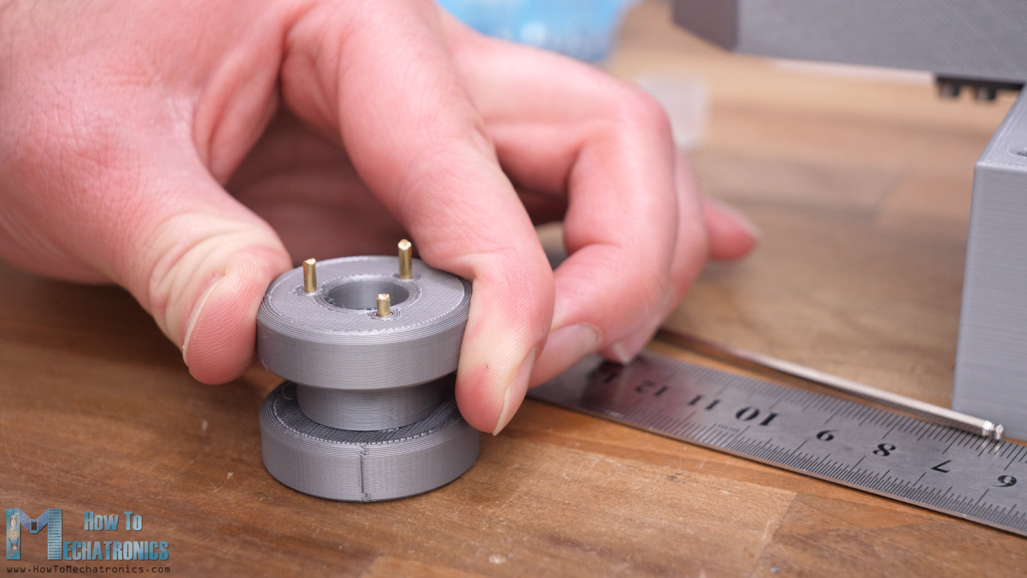
In this way we have to connect the two sections, and I decided to use the 2mm steel rods for that purpose, the same one that I will use for connecting the track links together. This is actually a brass rod used for welding, which is somewhat soft and can be easily cut to size with just pliers.
I inserted three rods with around 23mm length for each wheel, and then also installed two of the same bearings that I used before on both sides of the wheel. Again, as previously, using an M4 bolt, a washer and a self-locking nut I secured the roadwheel in place.
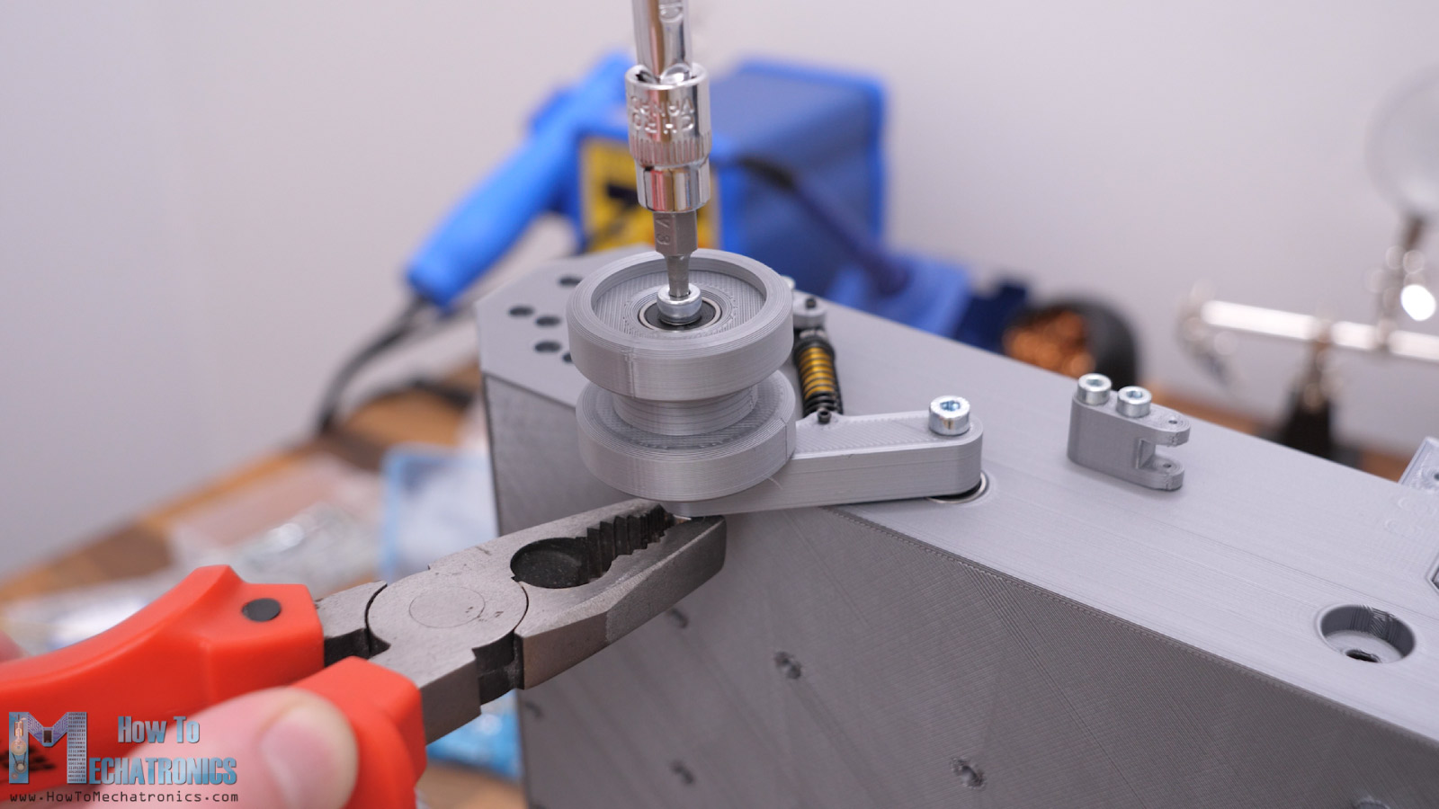
The wheel should be able to rotate freely while not having any play in the shaft.
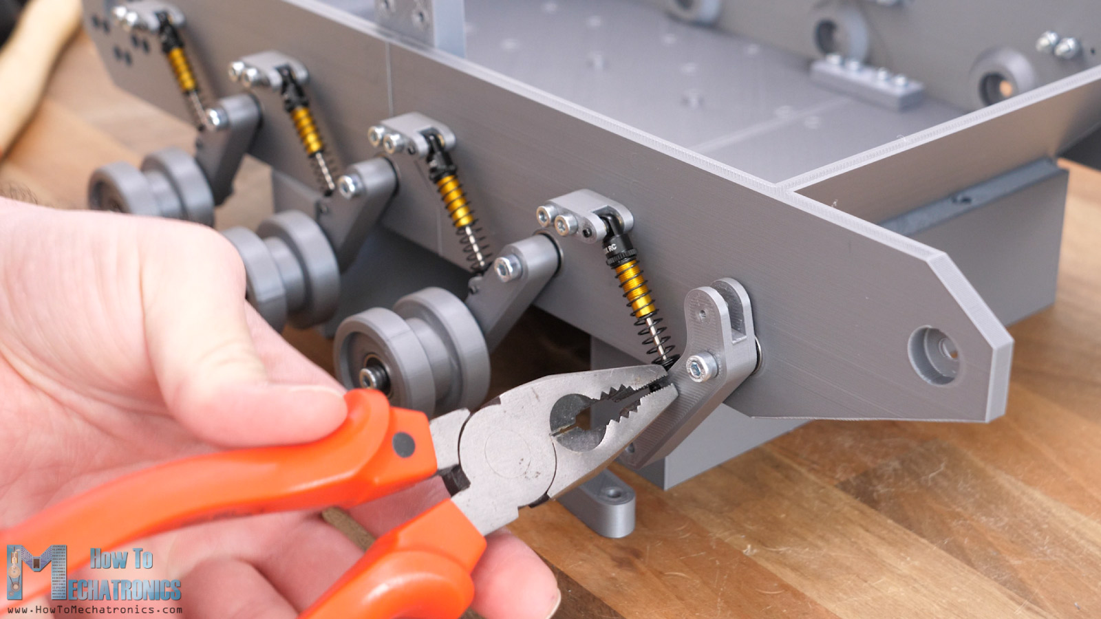
Now we just have to repeat this process for the other roadwheels. As for the front roadwheel, we have a slightly different arm which has a lever that will provide dynamic tension for the track, but the installation is the same.
Next, we can assemble the mechanism for the idler wheel. It’s composed of three 3D printed parts, some bolts and a distance nut.
Before securing the first link in place, we should add an M4 self-locking nut on the back side, on which we will later attach the idler wheel.
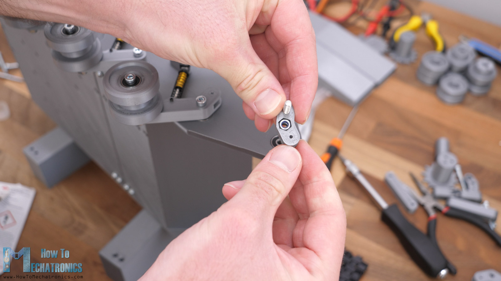
I’m using the same 2mm copper rods as pins for these joints. Now at the second link at the idler wheel side, we can secure one 15mm long M3 distance nut with the help of an M3 bolt.
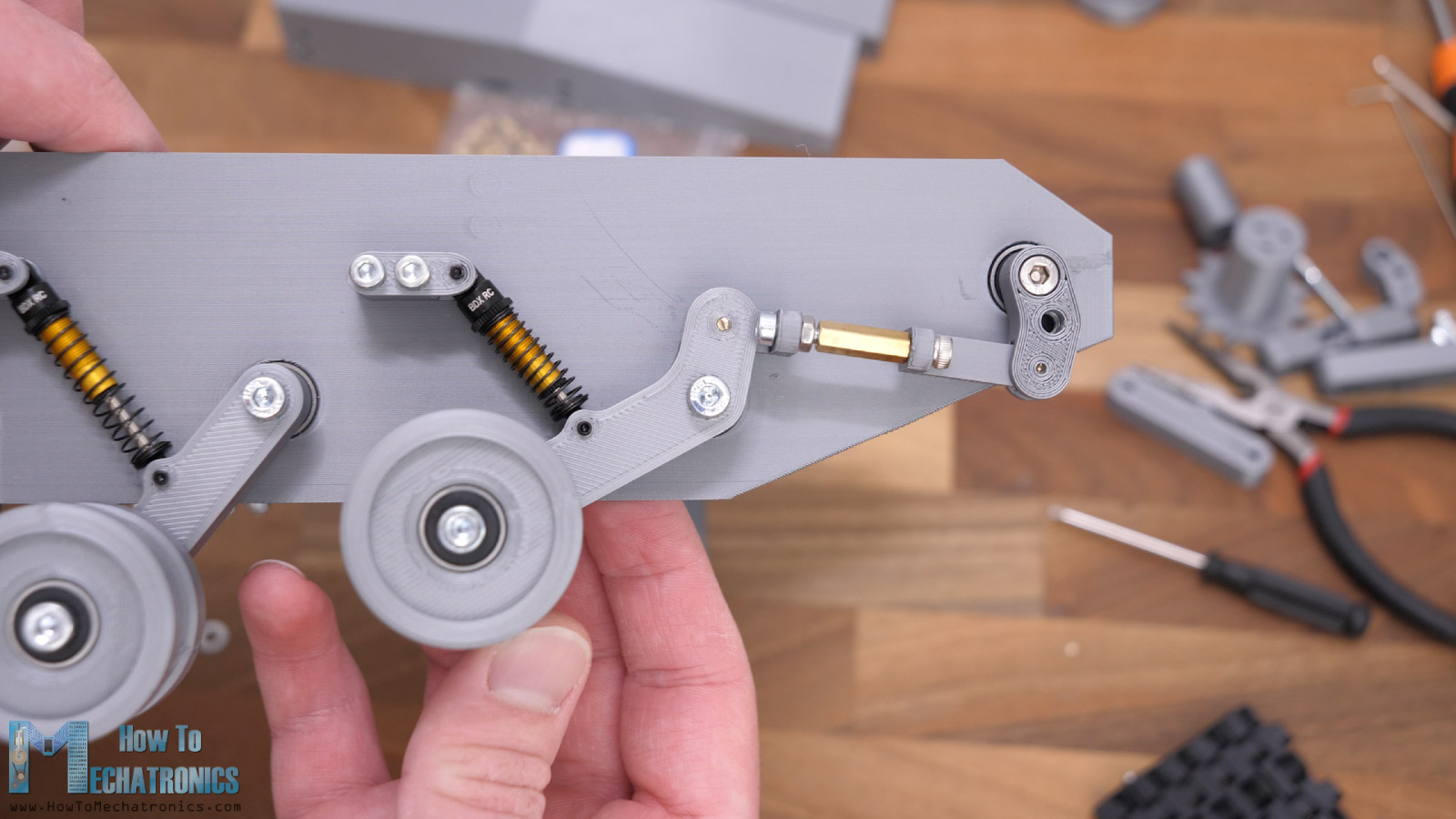
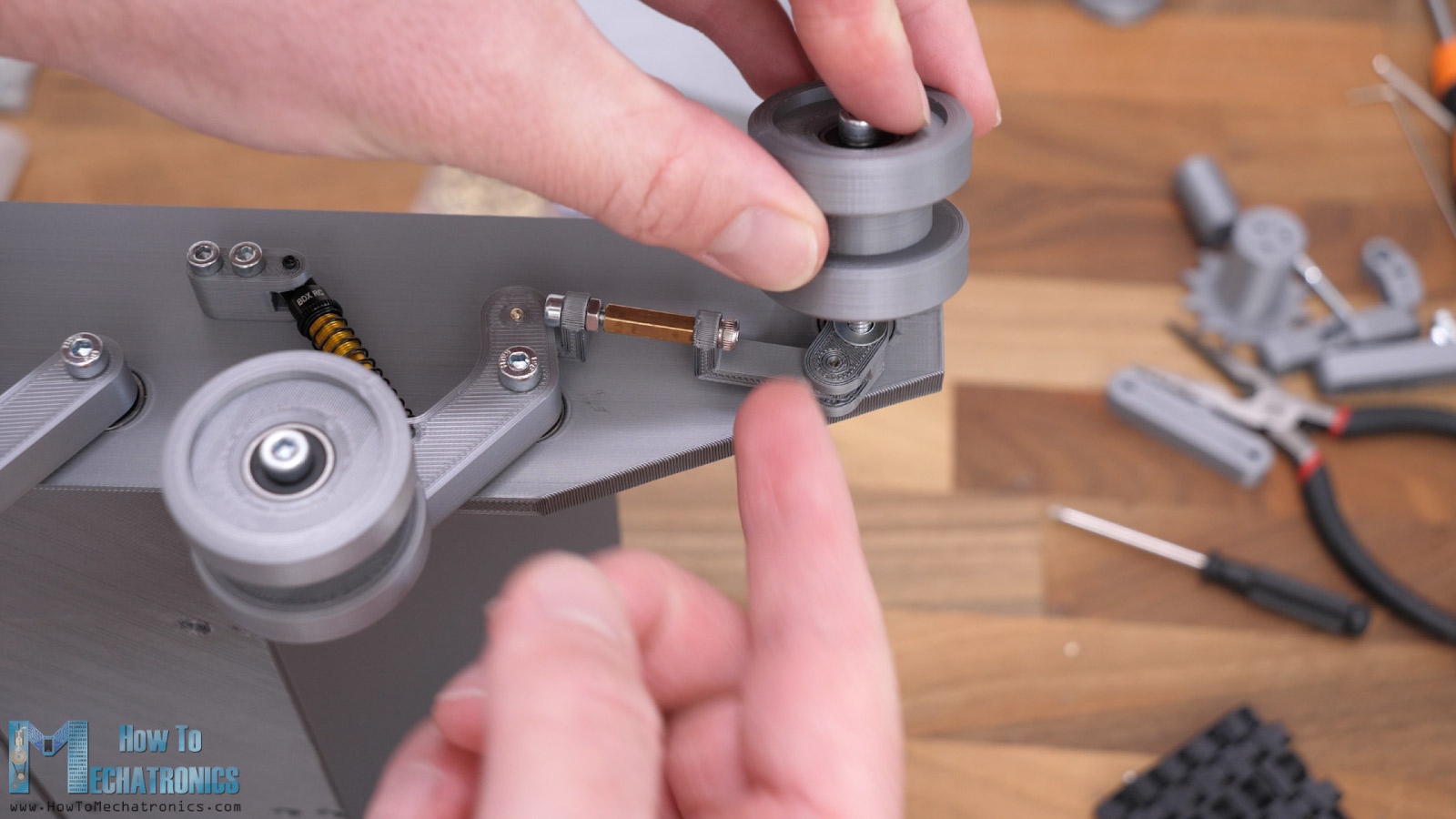
On the other side we put a 20mm long M3 bolt and a nut, that will go into the distance nut. With this setup now we can adjust the distance between the idler wheel and the road wheel arm and so we can tension the track both statically and dynamically. Then we can simply secure the idler wheel in place with an M4 bolt, and so we have this tension system done as well as the whole suspension system.
All right, so next we can assemble the sprocket and for that purpose first we need to install the motor. I designed the base platform to accept motors with 37mm diameter with either central or offset axis.
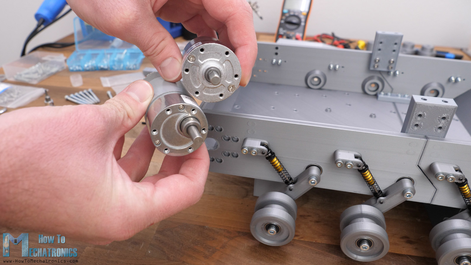
We can install any 12V DC motor with RPM ranging from 20 to 1000 RPM, depending on the application of the robot platform of course, but we will talk about that a bit later in the video. The motor is secured in place with six M3 bolts.
In order to attach the sprocket to the motor shaft, first we need to prepare the shaft coupler, or install some threaded inserts in it.
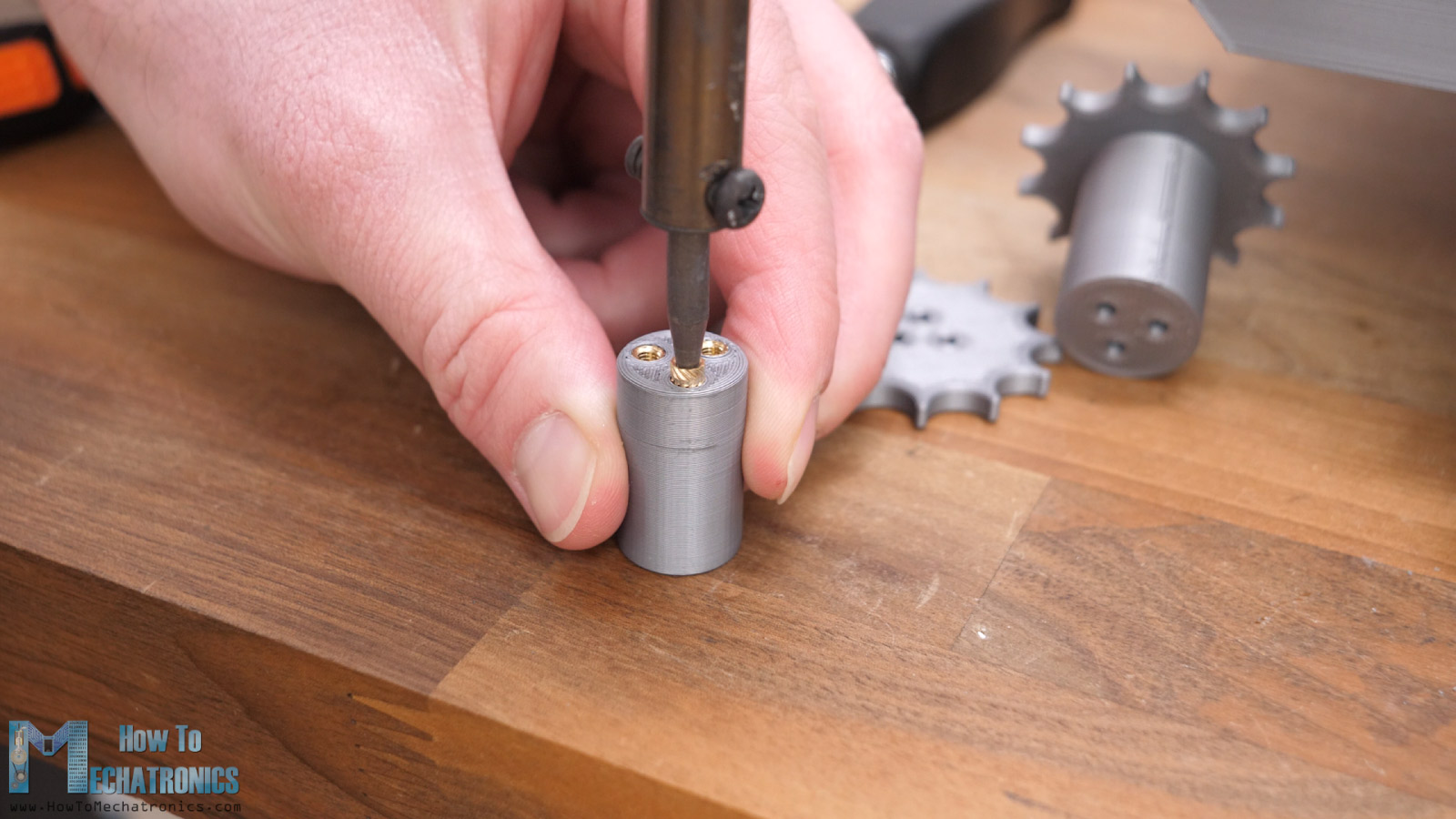
Then we can insert the coupler in place and secure it with an M3 grub screw.
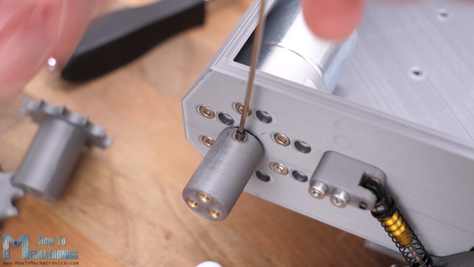
The two sections of the sprocket are then inserted and secured using three M3 bolts.
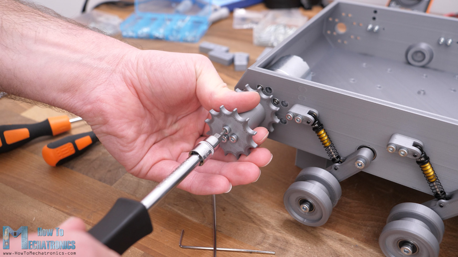
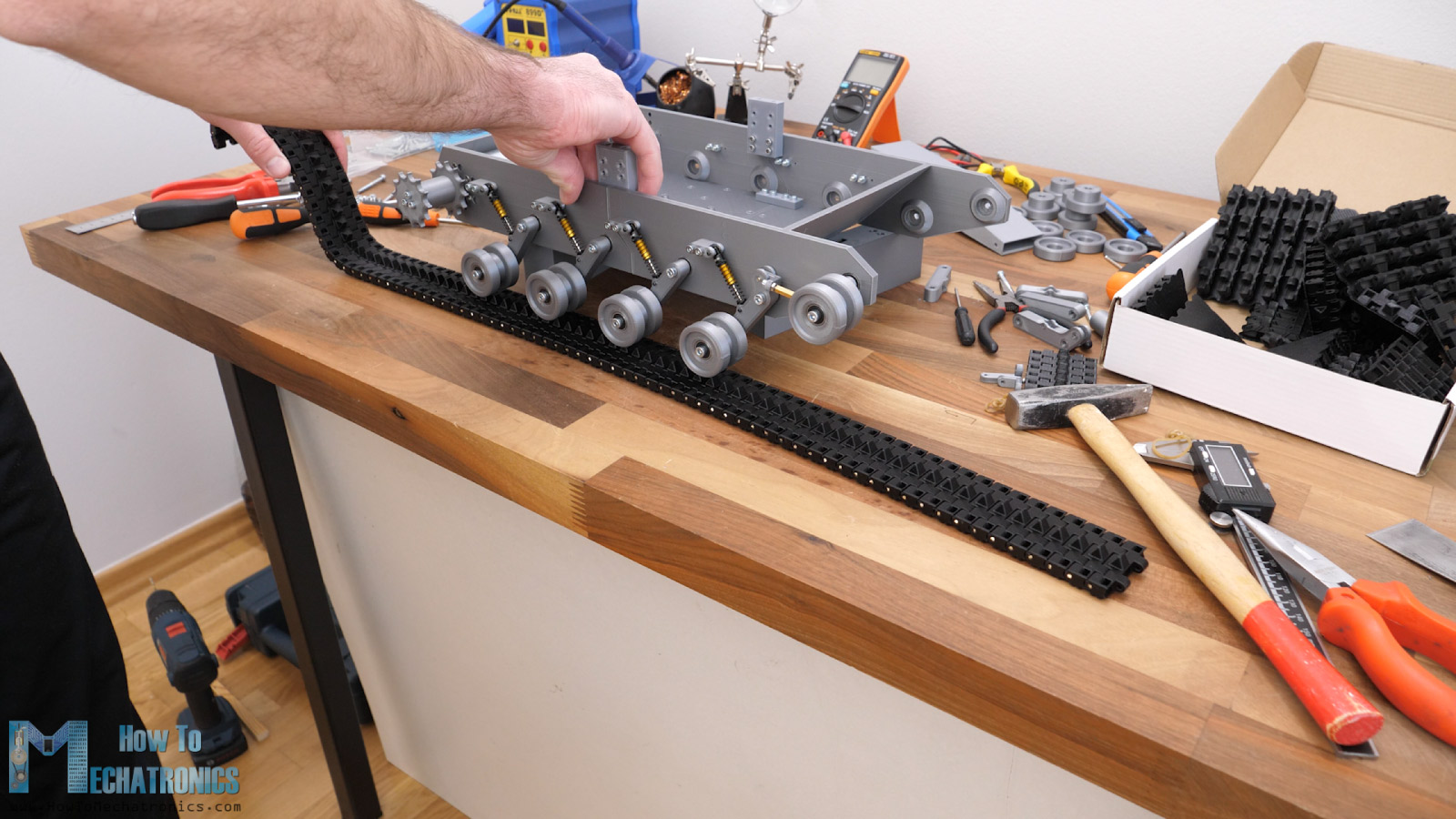
So here we have the platform drive train completed and now it’s time to have some fun assembling the track. That’s right, I found it quite fun assembling the track.
Here’s a closer look at the track links from where we can see how simple and clean, they are.
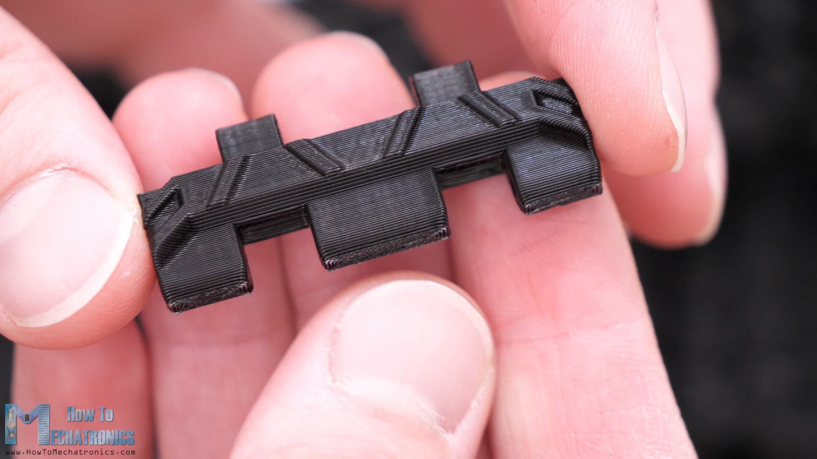
They come ready to use right away from the 3D printer because we are not using any support when 3D printing them. We just need 2mm pins for connecting them. Like I already said, we can easily get them from 2mm brass welding rods.
The outer holes on the links are tight fit so we need to use some force in order to insert them but that will ensure that they won’t come off. The inner holes on the links are loose fit which ensures a free rotation between the track links.
Now, we just have to make a cup of tea or a coffee and enjoy assembling them for a couple of hours. You realize the fun once you connect several of them and see how cool the track comes out. We need a total of 78 track links for assembling a single track. In terms of the rod length, we need around 3.5m for each track, as each pin should be around 43mm long.
Once we have the track ready, we can simply wrap it around the sprocket, the roadwheels and the idler wheel, and close the loop with another 2mm pin at the site. We can note here that with 78 track links the tension of the track is just right, though the last roadwheel moves a little bit up.
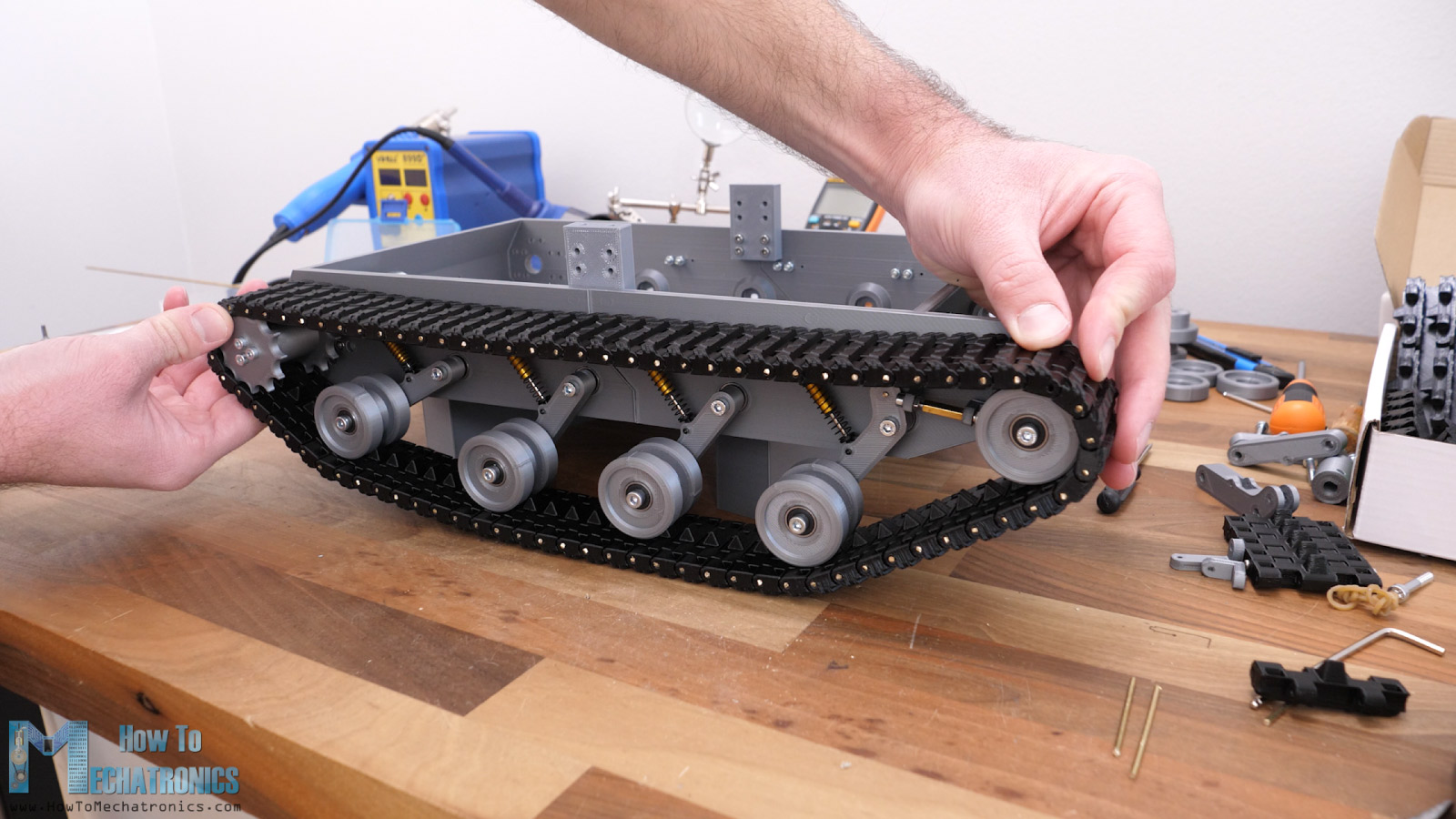
That’s actually so because the spring is not strong enough. We can adjust the spring tension a little bit by adjusting this nut on the shock absorber, though that wasn’t enough again. Therefore, I decided to change the original spring that came with the shock absorber, for a stronger one.
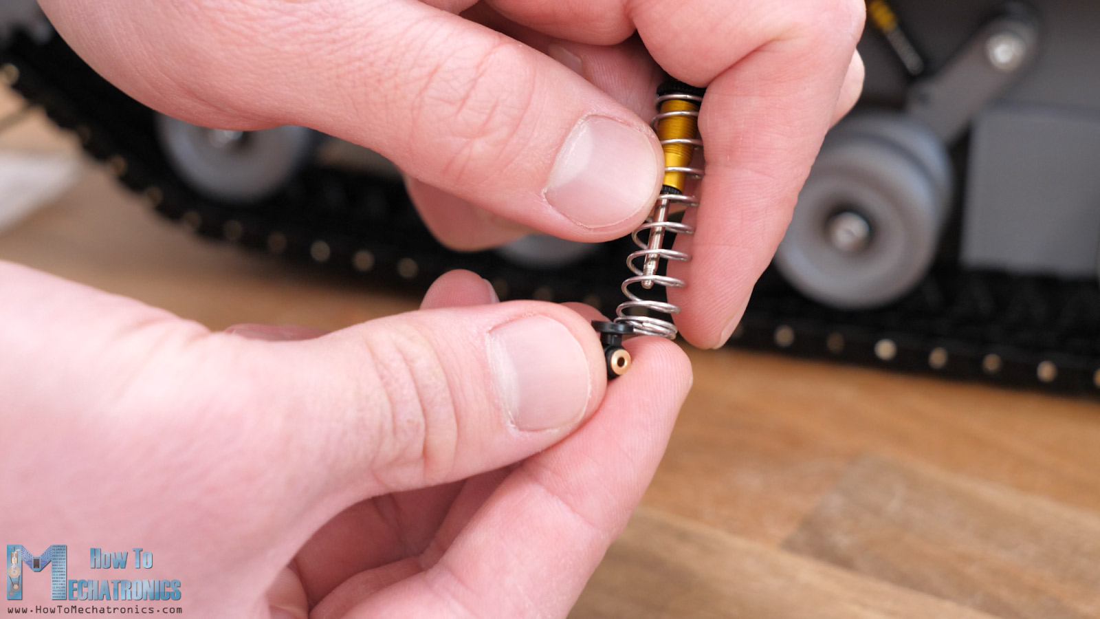
Changing the spring is quite easy, as we just have to unscrew one end of the shock absorber, insert the stronger spring, and screw the rod again. The spring I had was a bit wider than the original, so I had to use an M4 washer at the bottom side. Now this spring had enough force to hold the roadwheel in place when installing the tracks with 78 links.
I ended up changing the springs on all shock absorbers, because I realized that they wouldn’t be strong enough to carry the weight of the whole platform. This completes the whole drive system of the platform which I think turned out quite good.
If needed, we can now adjust the track tension with the distance nut at the idler wheel. Of course, it’s ok to have the track a bit loose so that it works properly. The loosen top section of the tracks is supported on the shock absorber brackets.
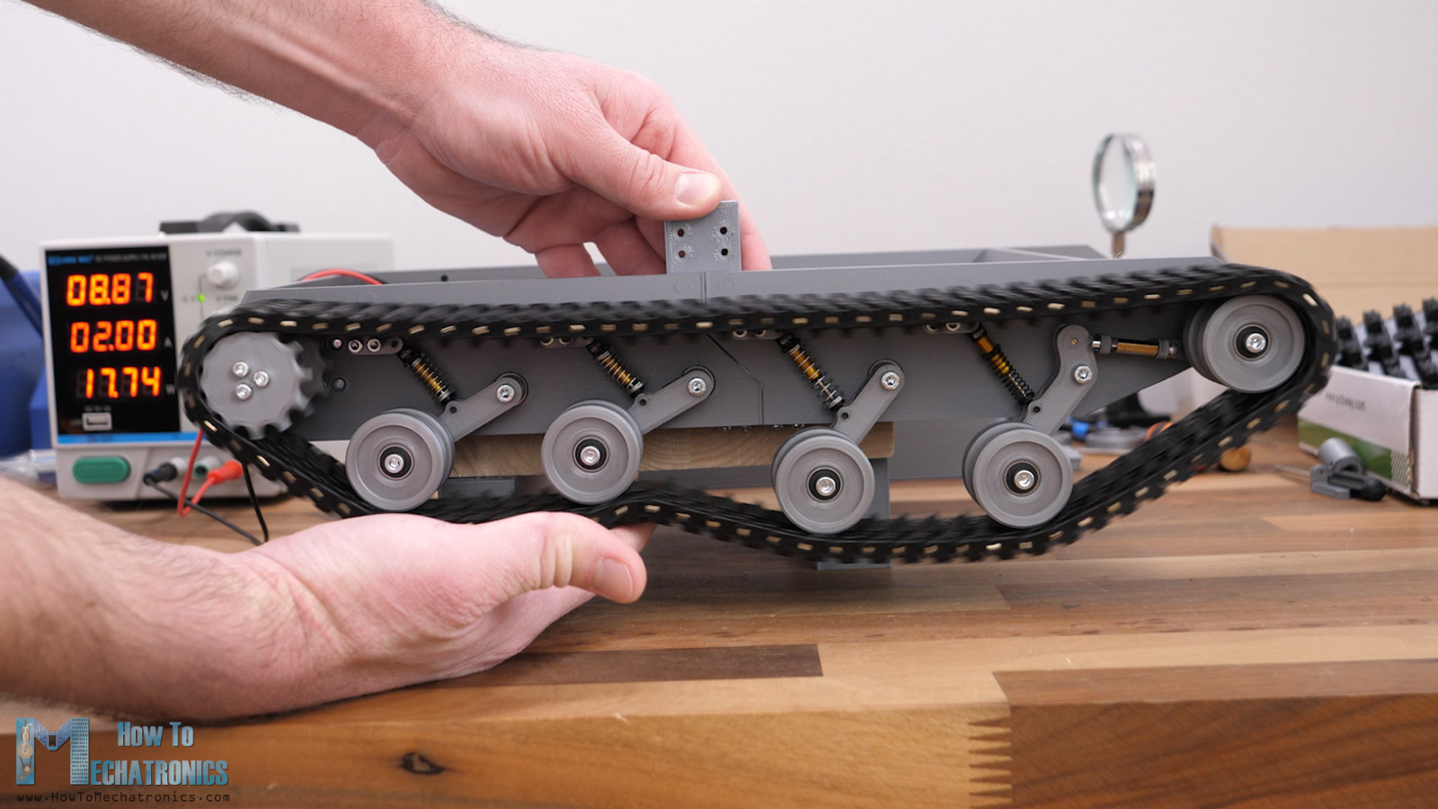
I connected the motor to a power to check how it will work. It seemed perfect to me. It’s really a great feeling to see something that you have created with that many 3D printed parts in action.
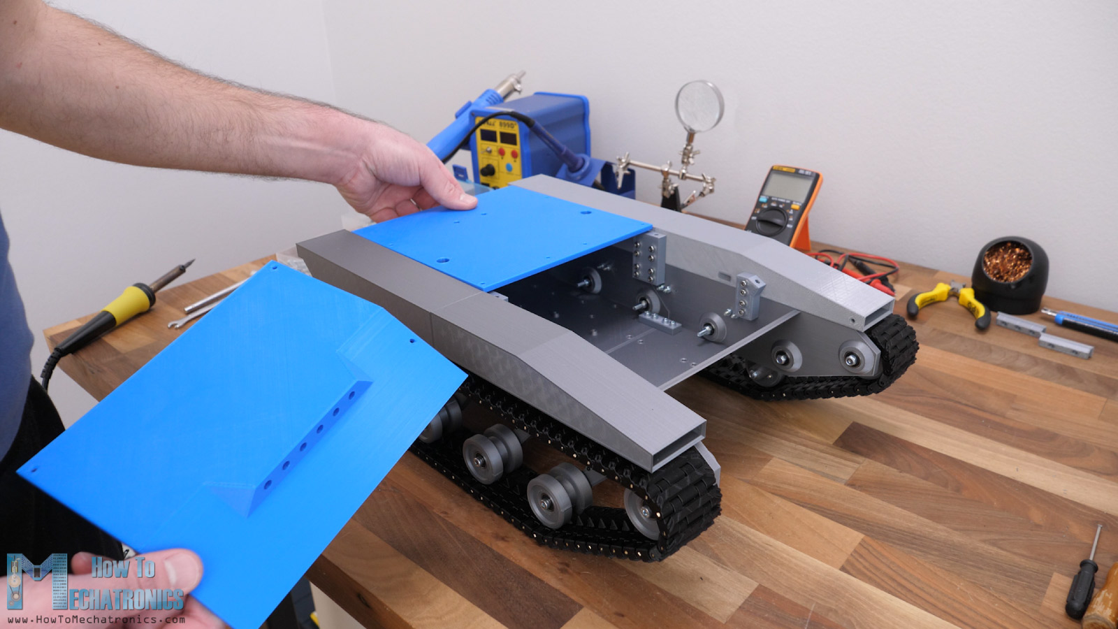
Obviously, we have to repeat the same procedure to assemble the other side. With this done, robot platform is like 80% finished. Next, I’m going to install the side panels which are mostly here for visual appearance.
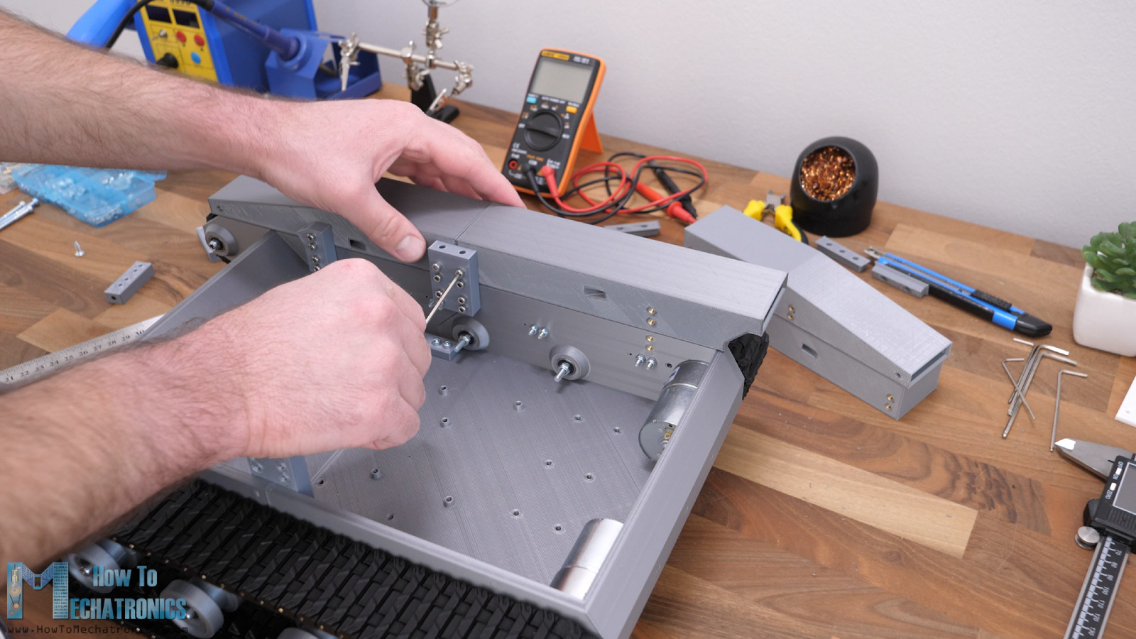
We secure them in place with the help of some brackets and M3 bolts. At the top go to covers which will enclose the platform. For this video I designed it this way just for the visual appearance.
Like I mentioned earlier, in some of my future videos, I plan to add a robotic arm or a turret on top of this platform, which means I will then have to design the tops appropriately.
You Might Also Like
Electronics – Robot Platform Circuit Diagram
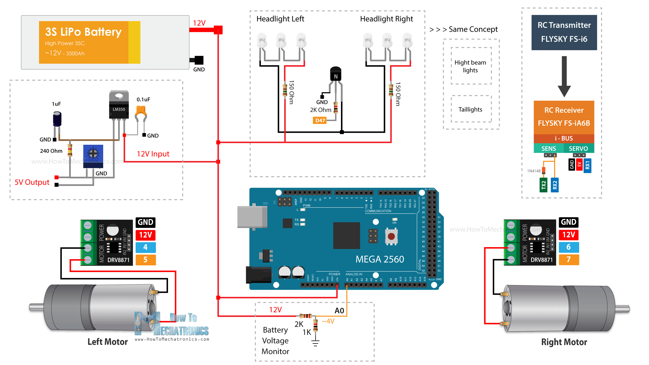
Now we can move on with the electronics of this project. Like I said, I will use an ATmega2560 microcontroller-based board.
You can get the components needed for this project from the links below:
- 2x 12V DC Motor – 50 to 500 RPM ………. Amazon / AliExpress
- DRV8871 DC Motor Driver ……………….…. Amazon / AliExpress
- Arduino MEGA…………………………….….…..… Amazon / AliExpress
- 3S LiPo Battery ………………………..………….. Amazon / AliExpress
- XT60 Connector …………………………..……… Amazon / AliExpress
- FLYSKY RC Transmitter …………………………. Amazon / AliExpress
Disclosure: These are affiliate links. As an Amazon Associate I earn from qualifying purchases.
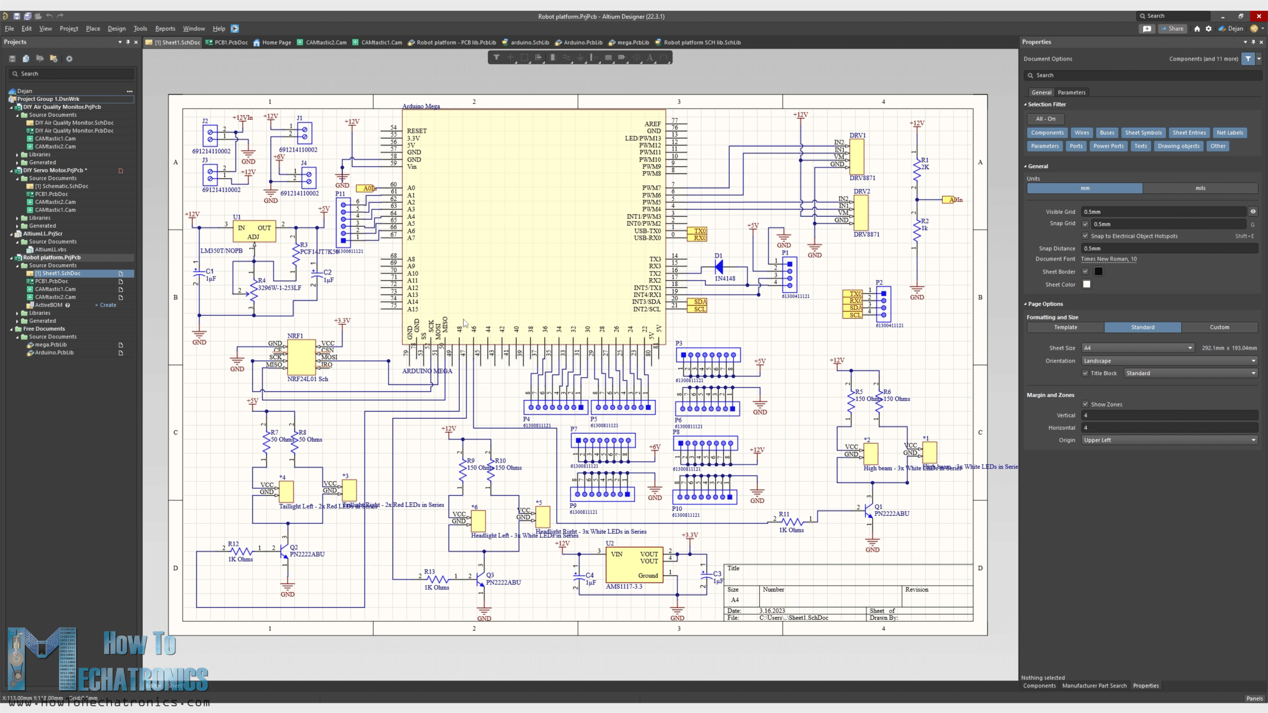
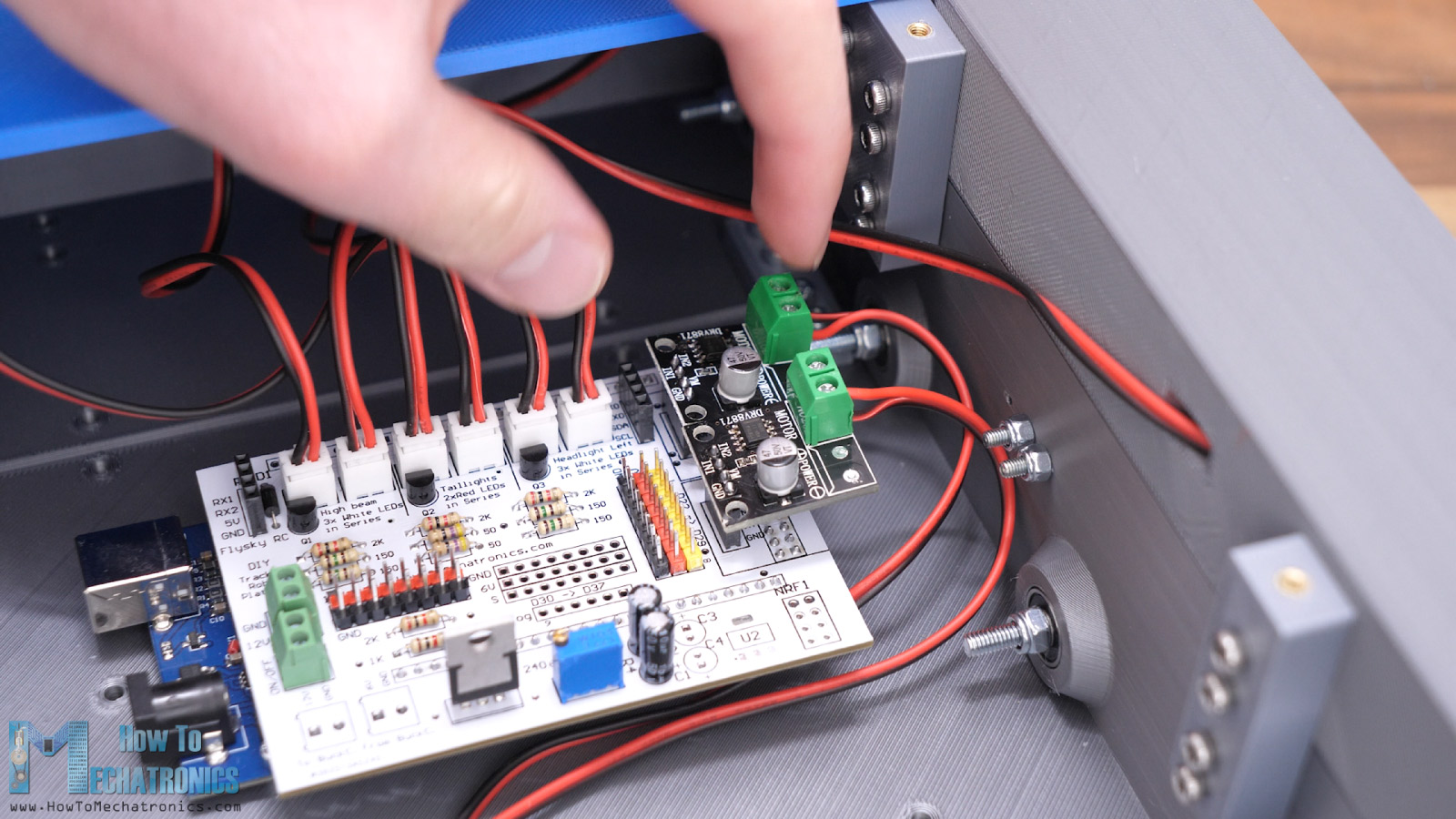
For driving the two motors I will use two DRV8871 DC motor drivers, which support PWM control and up to 3.6A peak current. The DC motors operating voltage is 12V, and we will power everything with 3S LiPo battery with gives around 12V. I also included a 5V voltage regulator, the LM350 IC, in order to have a dedicated 5V supply for other future uses, for example, for connecting servo motors to it. In this video we will use this 5V for powering the RC receiver and some of the LEDs.
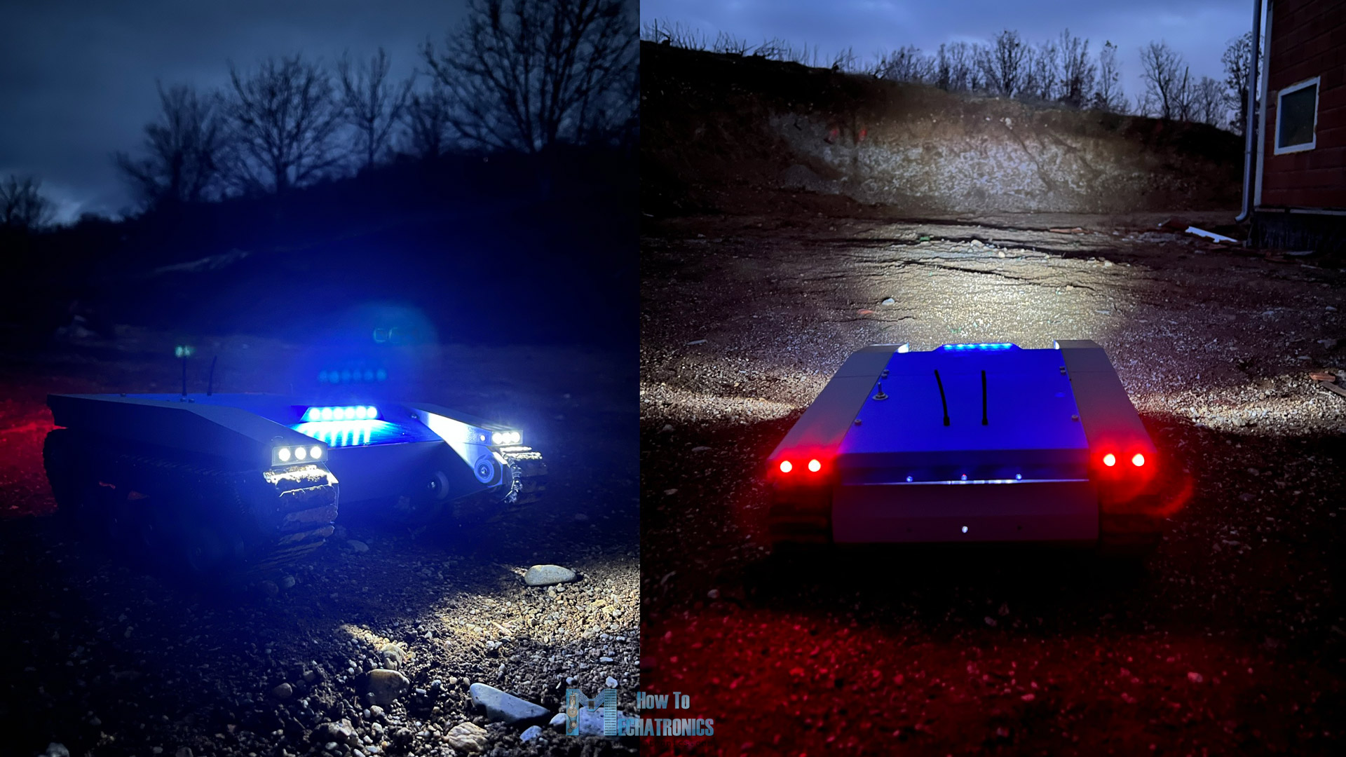
The LEDs I’m using for this project are simple 5mm LEDs in white and red color. I arranged them as follows:
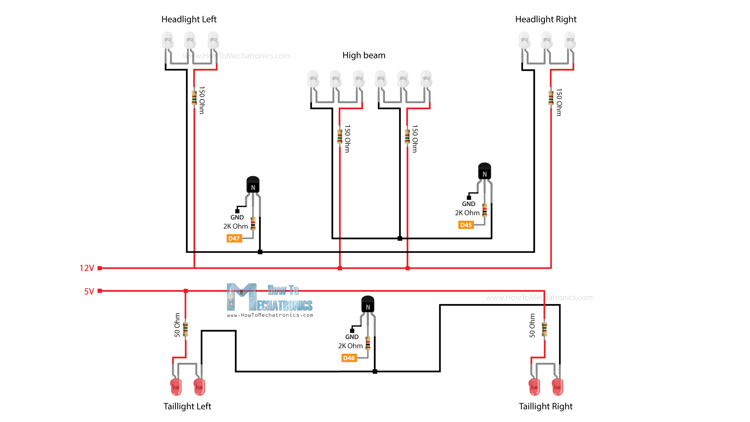
At the back we have two red LEDs on each side as Taillights, and in the front three White LEDs on each side as headlights. Additionally, there are six LEDs at the top cover as High beam lights. In order for these LEDs to light up properly we need a suitable circuit which includes resistors for limiting the current. I combined their connections both in parallel and in series.
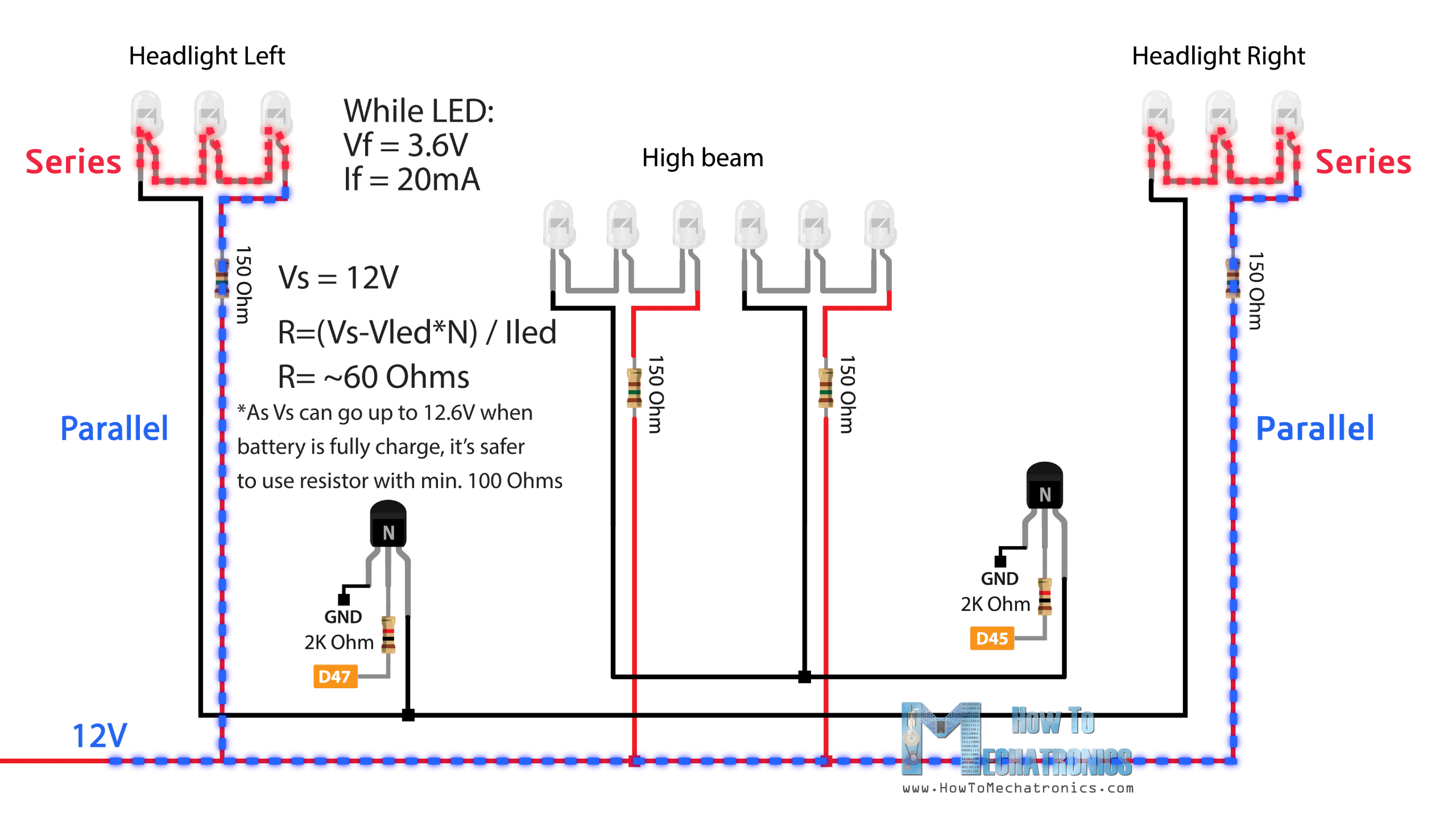
For example, for the front headlights, I’m using two parallel lines with 12V to power the 6 LEDs, 3 on each side left and right, which are connected in series. According to the LEDs forward voltage and current, I calculated the required resistor value for each line, and that was 150 Ohms for this case. For activating the LEDs, I am using some general-purpose NPN transistors rated at 200mA.
Lastly, I made a simple voltage divider which I will use for monitoring the battery voltage. Simply, the 12V from the battery are dropped to under 5V so they can go into an analog input in the microcontroller. In the program we can translate the value back to real voltage value and send it from the RC receiver to the RC transmitter where we can see the value on the display.
Custom PCB Design
I actually ended up with quite a lot of connections, so in order to avoid a mess I had to design a custom PCB for this project.
The PCB will be compatible with the ATmega2560 microcontroller based board to be directly mounted on top of it.
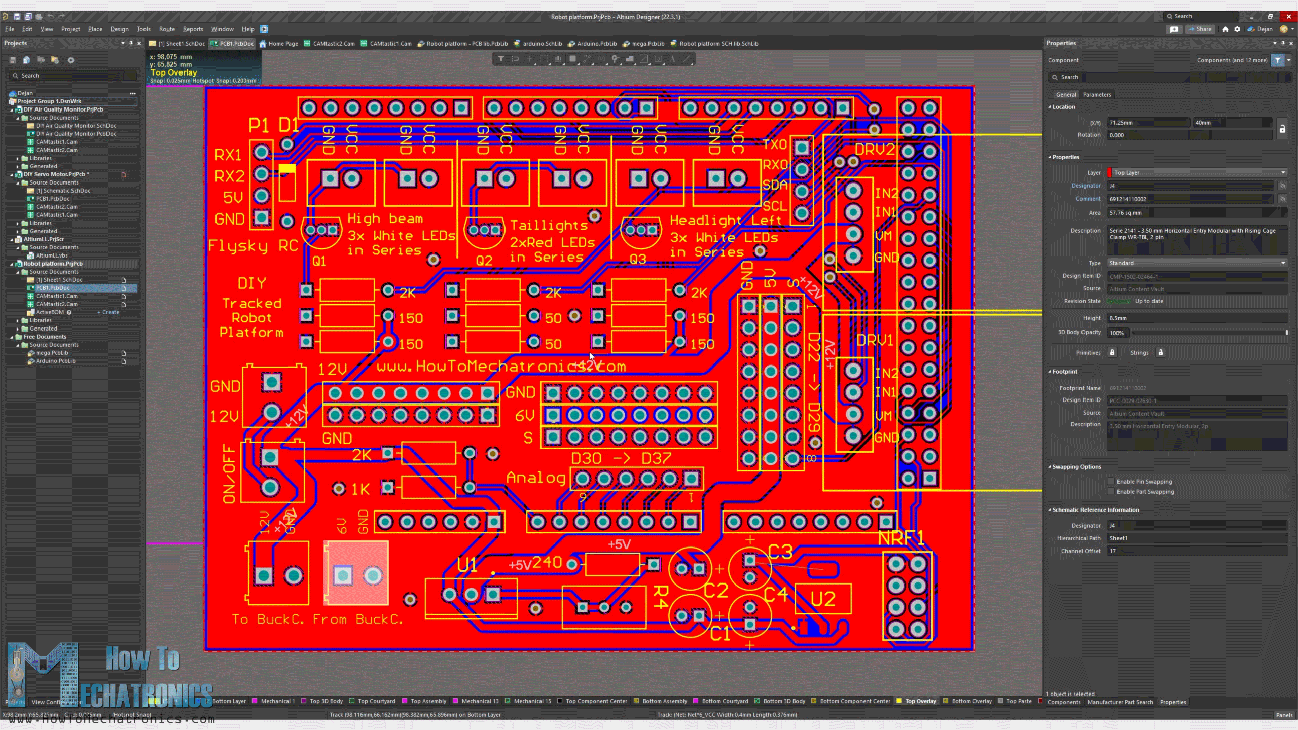
I included a 3.3V voltage regulator and a connection for a NRF24L01 transceiver module in case we want to control the platform with that module. Also, I included a 12V rail, and 5V and 6V rails with digital pins connections arranged for connecting servo motors to them. The 6V rail can be powered with an external buck converter.
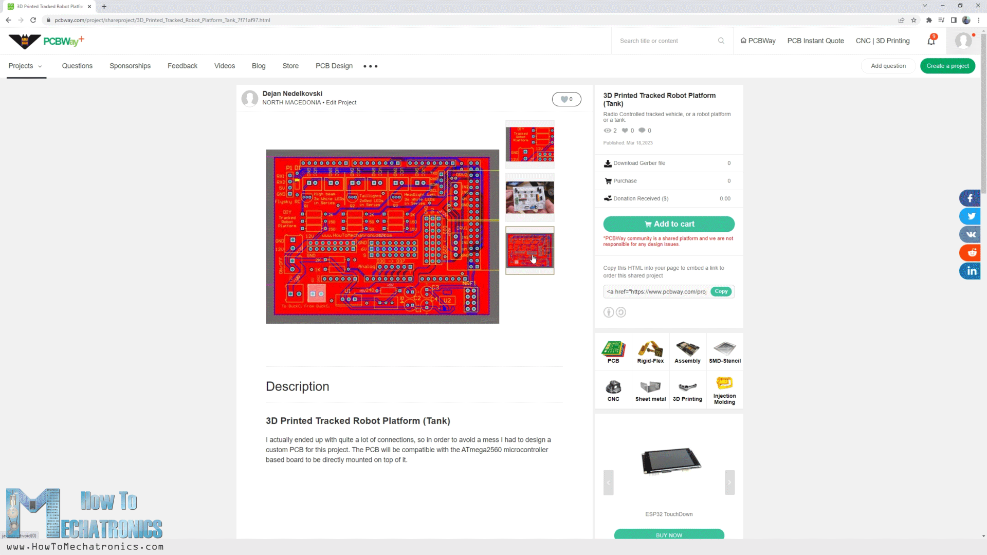
I ordered the PCB from PCBWay. Here we can simply upload the Gerber file, choose the properties of our PCB, and order it at a reasonable price.
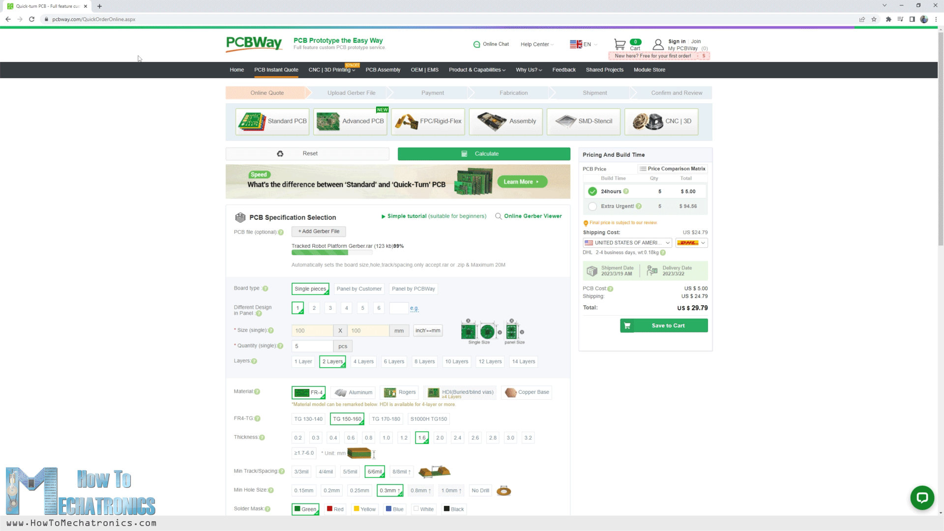
I didn’t change any of the default properties except for the PCB color which I chose to be white. You can find and download the Gerber from the PCBWay projects sharing community through which you can also directly order the PCB.
Also, you can download the Gerber file here:
Nevertheless, after several days the PCB arrived. The quality of the PCB is great, and everything is exactly the same as in the design.
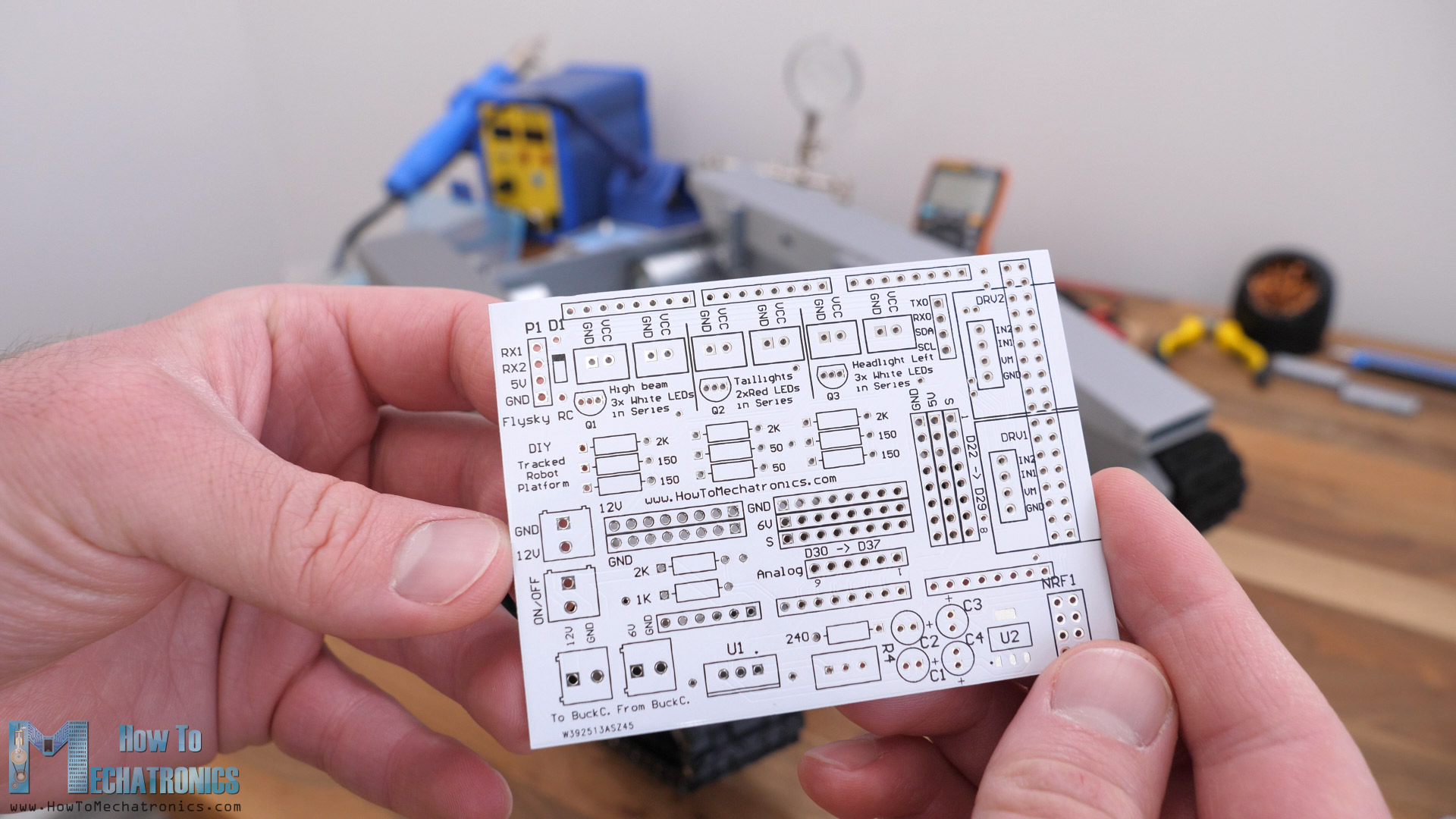
Assembling the PCB is pretty straight forward as everything is labeled. I started with soldering the pin headers at the bottom of the PCB, for the ATmega2560 connection and then continued with top side. For convenience we should first solder the smaller components, like the resistors and the transistors, and then the bigger ones like the LED and power connectors.
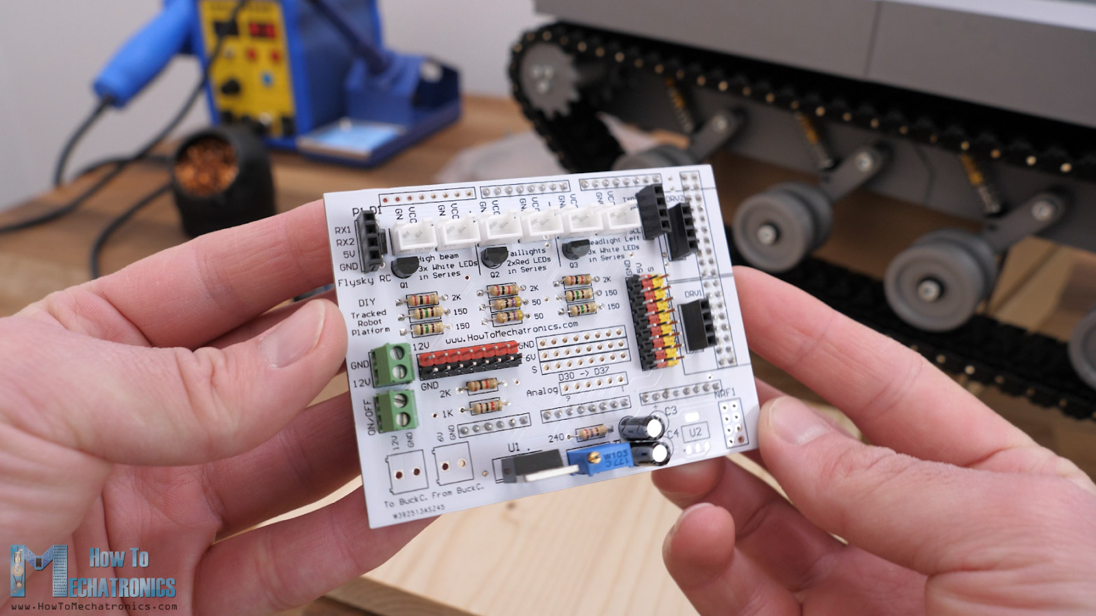
I used pin headers for all connections, because it gives flexibility to make changes if something doesn’t work properly. I didn’t solder the connectors for the external buck convertor and its rails, as well as the 3.3V voltage regulator, as I wasn’t going to use them now anyway. I really like how nice and clean this PCB came out with this white color.
Finishing the 3D Printed Tank Assembly
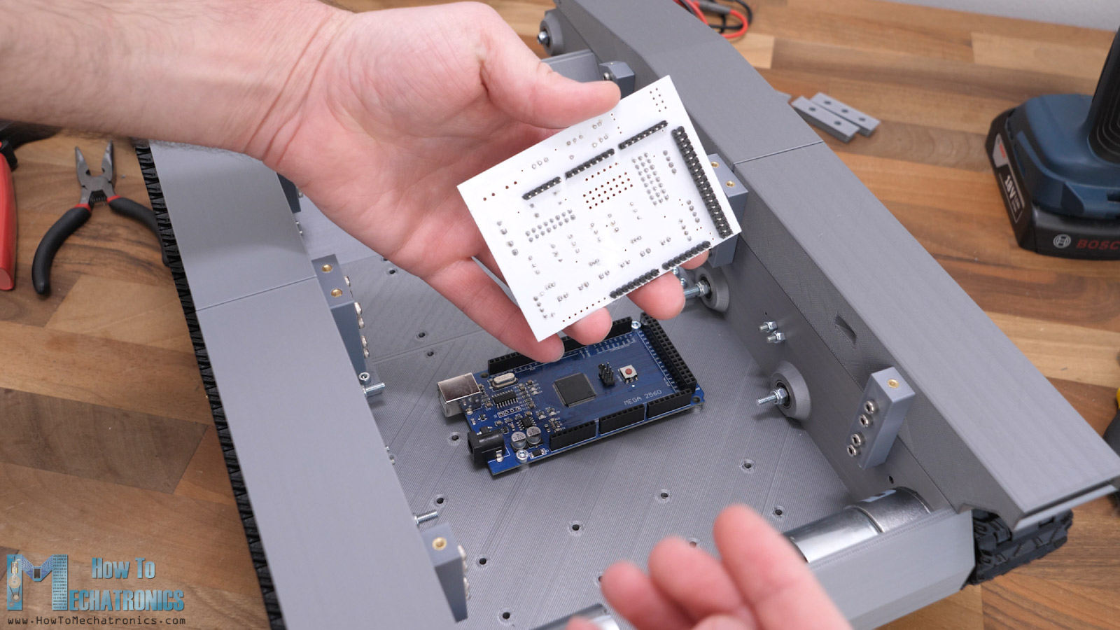
Ok, so first, we secure the microcontroller board in place with some M3 bolts, and then on top of it goes the custom PCB.
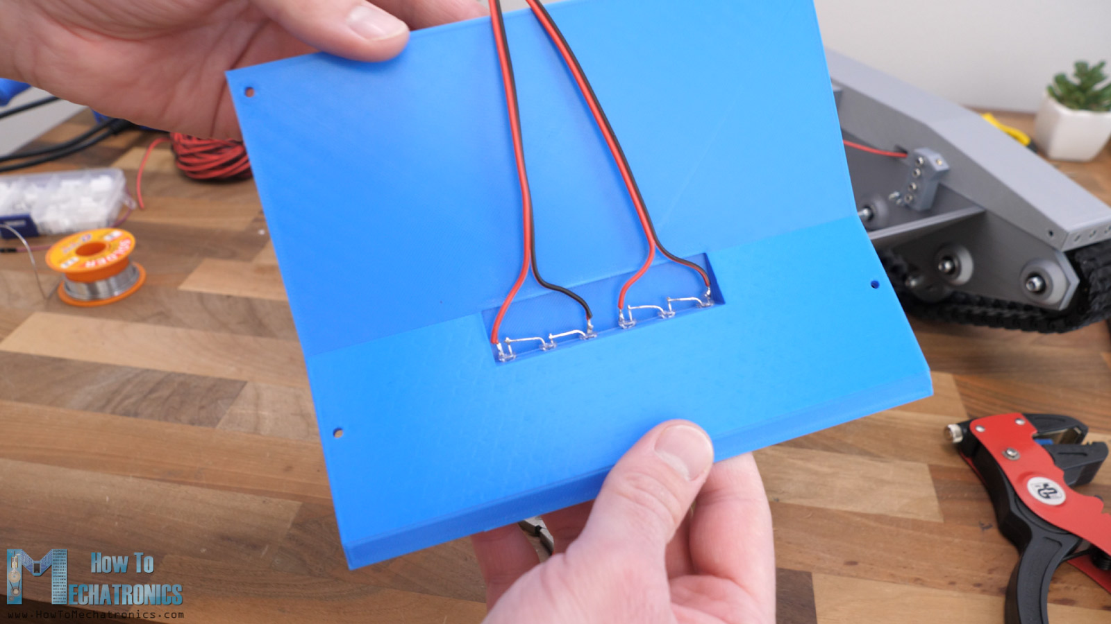
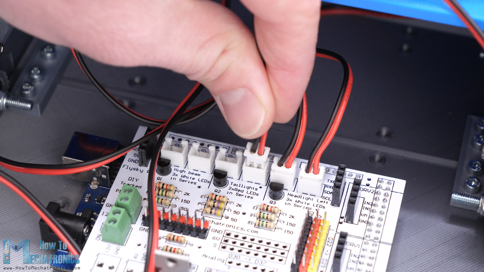
Now it’s time to install the LEDs. They will be fitted in the side panel with the help of these holders that accommodate the 5mm LEDs. As described in the schematics, we should solder each line of LEDs in series.
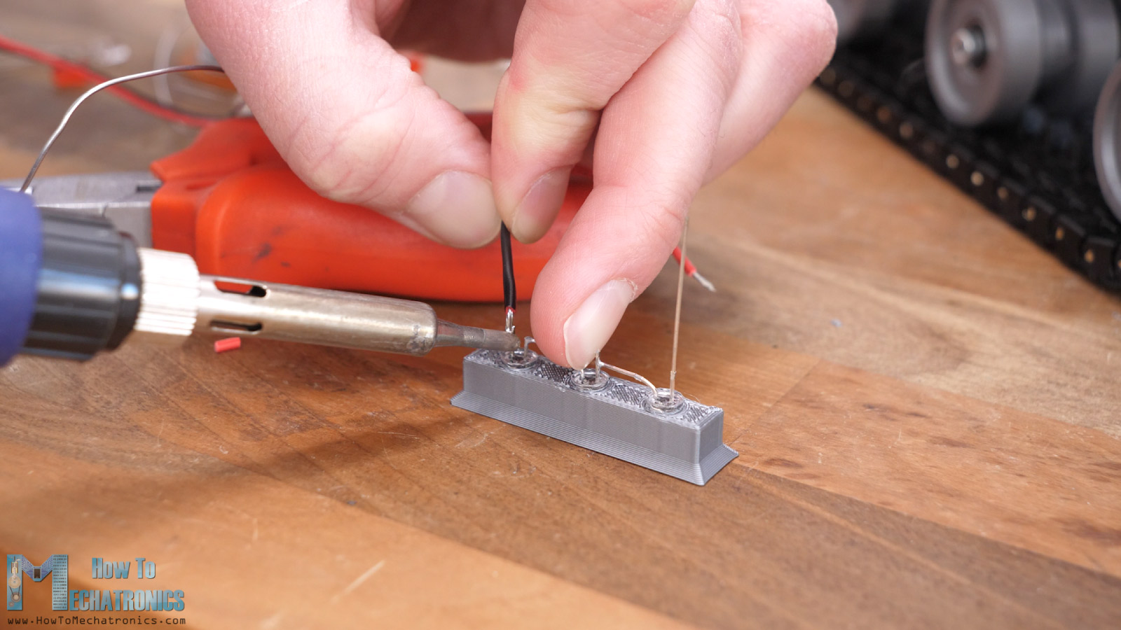
At the cathode goes the black wire and at the anode goes the red wire. We pass these wires through a small opening in the side panels that lead to the PCB.
The LED holder part is designed to make a tight fit with the side panel so once inserted in place we get a nice and clean look.
The high beam LEDs are placed directly on the top front cover.
For connecting the LEDs, I soldered XH2.54mm dupont male connectors on the PCB, so I had to install a suitable dupont female connector to the wires. We need crimping pliers for that purse but at the time of making this project I didn’t have one with me.
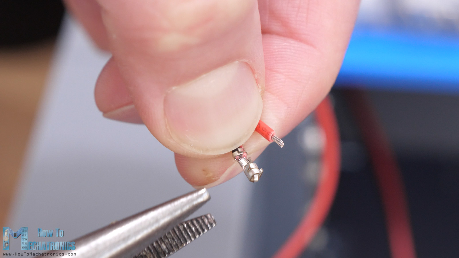
I used regular small pliers to do that job, and the connections came out just fine. Each LED line should go into the appropriate connector which is labeled on the PCB.
As for the motors, I didn’t have a suitable connectors so I soldered the wires directly to them. The motor connection goes into the DRV8871 driver board and then into the PCB.
For the radio communication I’m using the FLYSKY RC transmitter and receiver which are really affordable and work great.
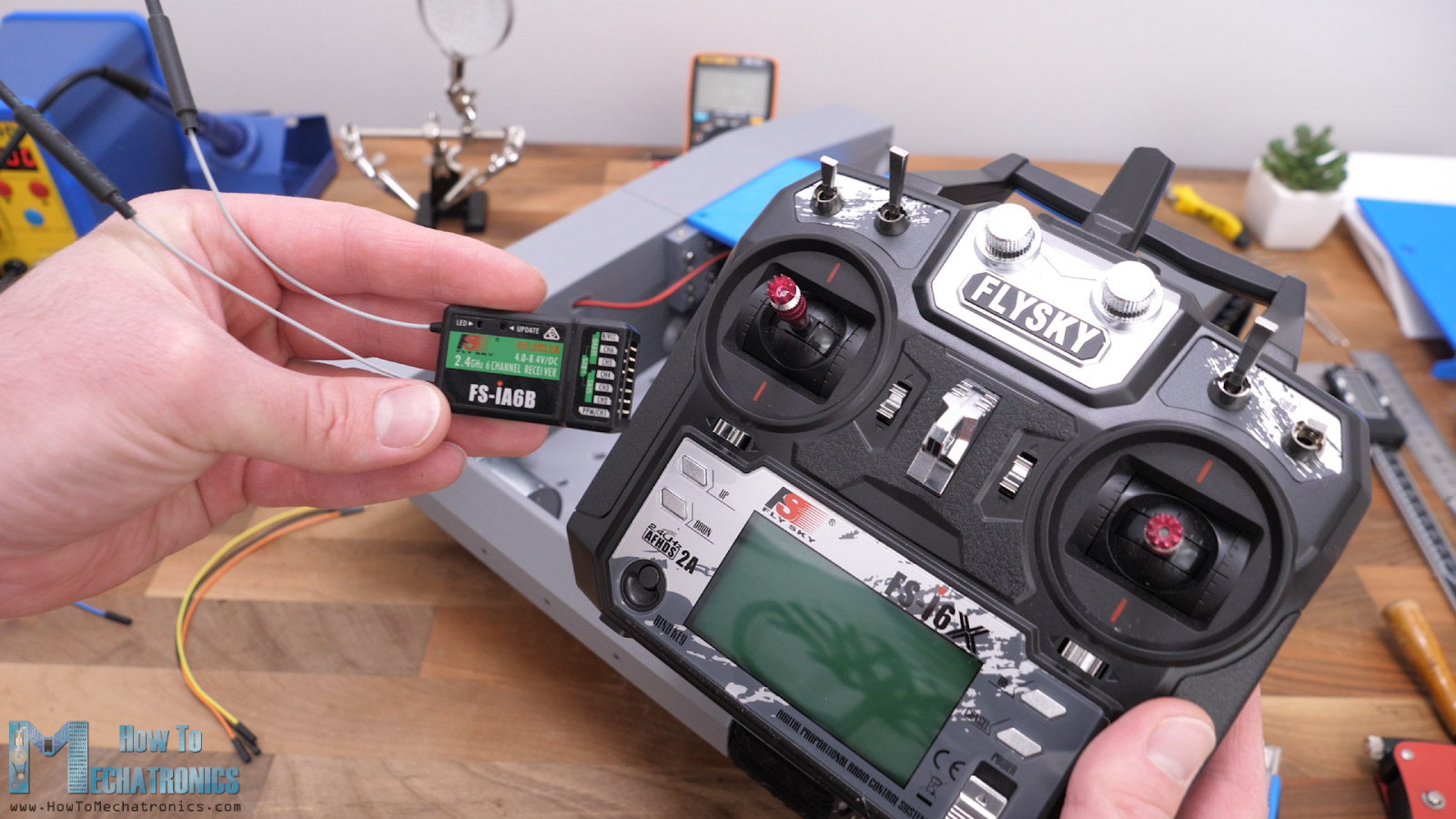
For connecting the receiver to the microcontroller, we can use jump wires. The receiver communicates with the microcontroller through an I-BUS and the serial port, so we need just three wires, VCC, GND and the Signal pin.
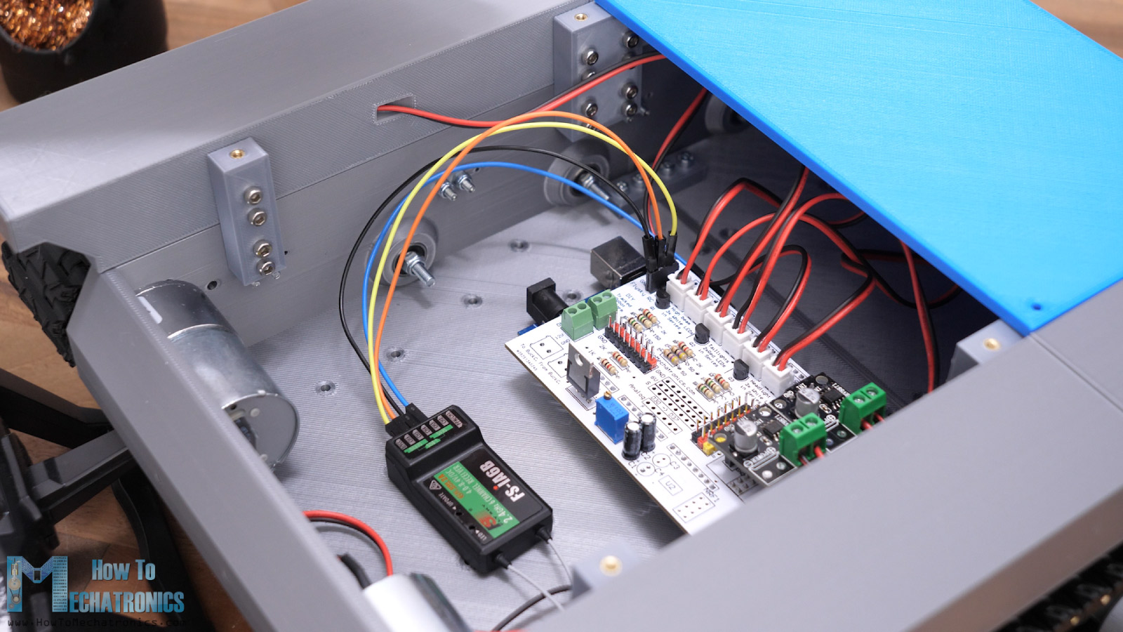
If we want to send data back from the receiver to the transmitter, in our case for monitoring battery voltage, we also need to connect the sensor I-BUS of the receiver to another serial port.
Lastly, we can connect the LiPo battery. Depending on the battery we need to have a suitable connector. This goes into the 12V connector and right next to it we have an ON/OFF connector to which will connect a switch for turning on and off the power of the platform.
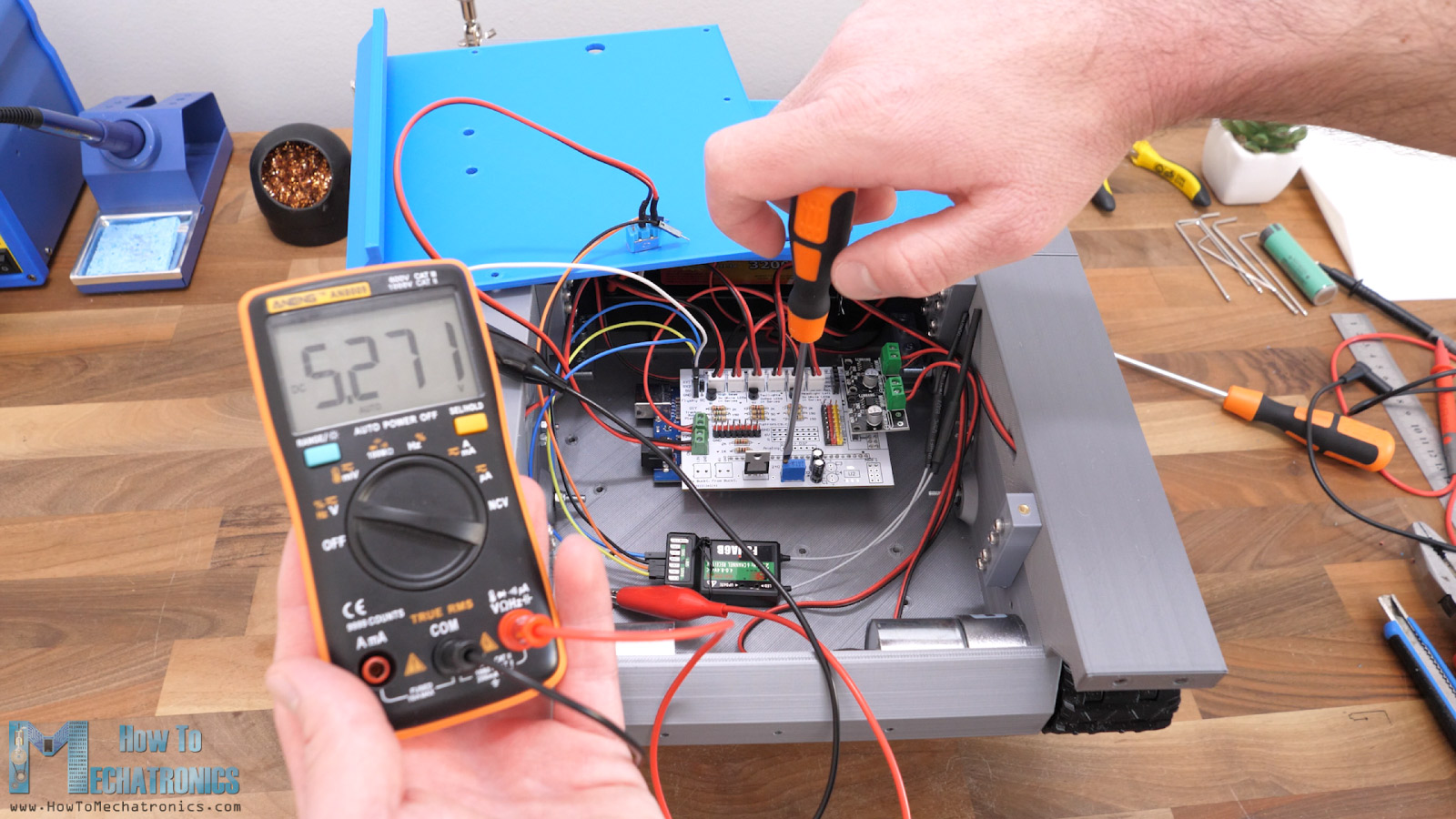
Please note here that before powering the board, we should first remove the RC receiver from power and adjust variable voltage of the LM350 IC to 5V using the trimmer.
Now we just have to put the top back cover in place, and we are done with this project.
Programming the Robot Platform
Now we have to program the 3D printed tank / robot platform. Here’s the Arduino code for this robot platform.
/*
      3D Printed Tracked Robot Platform - Arduino Code
      by Dejan, www.HowToMechatronics.com

     Libraries:
     IBusBM: https://github.com/bmellink/IBusBM
*/

#include <IBusBM.h>

#define motorLeft_IN1 4
#define motorLeft_IN2 5
#define motorRight_IN1 6
#define motorRight_IN2 7

IBusBM IBus;
IBusBM IBusSensor;

int ch0, ch1, ch6, ch8 = 0;

int motorSpeed, steeringValue, leftMotorSpeed, rightMotorSpeed = 0;

int ledBlinkPeriod = 50;
int isOn = LOW;
unsigned long time_now = 0;

void setup() {

  Serial.begin(115200);
  IBus.begin(Serial1, IBUSBM_NOTIMER); // Servo iBUS
  IBusSensor.begin(Serial2, IBUSBM_NOTIMER); // Sensor iBUS

  IBusSensor.addSensor(IBUSS_INTV); // add voltage sensor

  // DC motors control - set them stationary

  // Left track
  digitalWrite(motorLeft_IN1, LOW);   // PWM value
  digitalWrite(motorLeft_IN2, LOW); // Forward

  // Right track
  digitalWrite(motorRight_IN1, LOW);   // PWM value
  digitalWrite(motorRight_IN2, LOW); // Forward


  digitalWrite(46, LOW);
  digitalWrite(47, LOW);
  digitalWrite(48, LOW);


}

void loop() {
  // Reading the data comming from the RC Transmitter
  IBus.loop();
  // ch0 - left and right; ch1 - forward and backward;
  ch0 = IBus.readChannel(0); // ch0 - left and right;
  ch1 = IBus.readChannel(1); // ch1 - forward and backward;
  ch6 = IBus.readChannel(6); // ch6 - Headlights
  ch8 = IBus.readChannel(8); // ch8 - High beam


  // convert the incoming date into suitable PWM value
  steeringValue = map(ch0, 1000, 2000, -185, 185); // 0 to 185 range because then I add +70 in order to avoid low PWM values as to motors won't start if so
  motorSpeed = map(ch1, 1000, 2000, -185, 185);
  motorSpeed = abs(motorSpeed);

  leftMotorSpeed = 70 + motorSpeed + steeringValue; // 70 + (0-185) + (0 - 185 ) =  70 - 255 so this range from 70 to 255 is used as PWM value
  rightMotorSpeed = 70 + motorSpeed - steeringValue;

  leftMotorSpeed = constrain(leftMotorSpeed, 0, 255); // constrain the PWM value from 0 to 255
  rightMotorSpeed = constrain(rightMotorSpeed, 0, 255);

  // if PWM is lower than 72, set PWM value to 0

  if (leftMotorSpeed < 72) {
    leftMotorSpeed = 0;
  }
  if (rightMotorSpeed < 72) {
    rightMotorSpeed = 0;
  }
  // if right joystick goes up > move forward
  if (ch1 > 1510 && ch1 < 2000) {
    analogWrite(motorLeft_IN1, leftMotorSpeed);  // PWM input
    digitalWrite(motorLeft_IN2, LOW); // Direction - Forward

    analogWrite(motorRight_IN1, rightMotorSpeed);  // PWM input
    digitalWrite(motorRight_IN2, LOW); // Direction - Forward
  }

  // if right joystick goes down > move backward
  if (ch1 > 1000 && ch1 < 1420) {
    digitalWrite(motorLeft_IN1, LOW);  // Direction - Backward
    analogWrite(motorLeft_IN2, leftMotorSpeed); // PWM input

    digitalWrite(motorRight_IN1, LOW);  // Direction - Backward
    analogWrite(motorRight_IN2, rightMotorSpeed); // PWM input
  }
  // if right joystick is in the middle, don't move
  if (ch1 > 1420 && ch1 < 1520) {
    if (leftMotorSpeed < 75 && rightMotorSpeed < 75) {
      digitalWrite(motorLeft_IN1, LOW);
      digitalWrite(motorLeft_IN2, LOW);

      digitalWrite(motorRight_IN1, LOW);
      digitalWrite(motorRight_IN2, LOW);
    }
    // if right joystick move just left or right, without going up or down, move the tank left or right (only 1 motor move)
    else {
      analogWrite(motorLeft_IN1, leftMotorSpeed);  // PWM input
      digitalWrite(motorLeft_IN2, LOW); // Direction - Forward

      analogWrite(motorRight_IN1, rightMotorSpeed);  // PWM input
      digitalWrite(motorRight_IN2, LOW); // Direction - Forward
    }
  }

  // LEDs control

  // Headlights and Taillights LEDs control
  if (ch6 > 1500) {
    digitalWrite(47, HIGH);
    digitalWrite(48, HIGH);
  }
  else {
    digitalWrite(47, LOW);
    digitalWrite(48, LOW);
  }
  // High beam LEDs control
  if (ch8 == 1500) {
    digitalWrite(46, HIGH);
  }
  // If rocker switch in position 3 (2ooo value) - flasing with the high beam LEDs
  else if (ch8 == 2000) {
    if (millis() >= time_now + ledBlinkPeriod) {
      time_now += ledBlinkPeriod;
      if (isOn == HIGH) {
        isOn = LOW;
      }
      else {
        isOn = HIGH;
      }
      digitalWrite(46, isOn);
    }
  }
  else {
    digitalWrite(46, LOW);
  }

  // Monitor the battery voltage
  int sensorValue = analogRead(A0);
  float voltage = sensorValue * (5.00 / 1023.00) * 3.02; // Convert the reading values from 5v to suitable 12V
  // Send battery voltage value to transmitter
  IBusSensor.loop();
  IBusSensor.setSensorMeasurement(1, voltage * 100);
}Code language: PHP (php)
Code overview
So, using the IBusBM library we read incoming data from the RC Transmitter.
// Reading the data comming from the RC Transmitter
  IBus.loop();
  // ch0 - left and right; ch1 - forward and backward;
  ch0 = IBus.readChannel(0); // ch0 - left and right;
  ch1 = IBus.readChannel(1); // ch1 - forward and backward;
  ch6 = IBus.readChannel(6); // ch6 - Headlights
  ch8 = IBus.readChannel(8); // ch8 - High beamCode language: JavaScript (javascript)
The rightjoystick, channels 0 and 1 are used for controlling the motion of the platform, the two rocker switches, channel 6 and 8 for controlling the LEDs.
We convert the incoming data into values suitable for PWM control of the DC motors, which is from 0 to 255.
// convert the incoming date into suitable PWM value
  steeringValue = map(ch0, 1000, 2000, -185, 185); // 0 to 185 range because then I add +70 in order to avoid low PWM values as to motors won't start if so
  motorSpeed = map(ch1, 1000, 2000, -185, 185);
  motorSpeed = abs(motorSpeed);

  leftMotorSpeed = 70 + motorSpeed + steeringValue; // 70 + (0-185) + (0 - 185 ) =  70 - 255 so this range from 70 to 255 is used as PWM value
  rightMotorSpeed = 70 + motorSpeed - steeringValue;

  leftMotorSpeed = constrain(leftMotorSpeed, 0, 255); // constrain the PWM value from 0 to 255
  rightMotorSpeed = constrain(rightMotorSpeed, 0, 255);Code language: JavaScript (javascript)
We send the PWM values to the drivers and the motors using the analogWrite() function appropriately.
// if right joystick goes up > move forward
  if (ch1 > 1510 && ch1 < 2000) {
    analogWrite(motorLeft_IN1, leftMotorSpeed);  // PWM input
    digitalWrite(motorLeft_IN2, LOW); // Direction - Forward

    analogWrite(motorRight_IN1, rightMotorSpeed);  // PWM input
    digitalWrite(motorRight_IN2, LOW); // Direction - Forward
  }Code language: JavaScript (javascript)
Overall, the code is not that complicated as the robot platform itself doesn’t have complicated functions.
Testing the 3D Printed Robot – Tracked Robot Platform
Once we upload the code, we can power up the robot platform and the RC Transmitter for testing it out. On the transmitter display we can notice the LiPo battery voltage, as well as the receiver and the transmitter voltage.
And there we have it. Using the right joystick, we can control the motion of the platform. With the left rocker switch we control the headlights and the taillights LEDs, and with the right 3-way rocker switch the high beam LEDs. The high beam LEDs have two modes, always on and a flashing mode.
We can note here that the motors that I installed are actually a bit underpowered for this platform.
We can see that it takes the joystick to be almost at the top for the tracks to start moving. Plus, I can stop the track very easily with my hand. The suspension system and the tracks themself cause a lot of tension and resistance to the motors. These motors are 888RPM which is fine in terms of speed, but they are the smaller motors, rated just under 500mA.
So, I replaced them with my other bigger motors that I had but I actually got almost the same results. Although these were more powerful motors, their speed reduction was smaller, or they had higher RPM of 1280, and so I got the same results.
Actually, they are not that bad. The robot platform runs quite well with them.
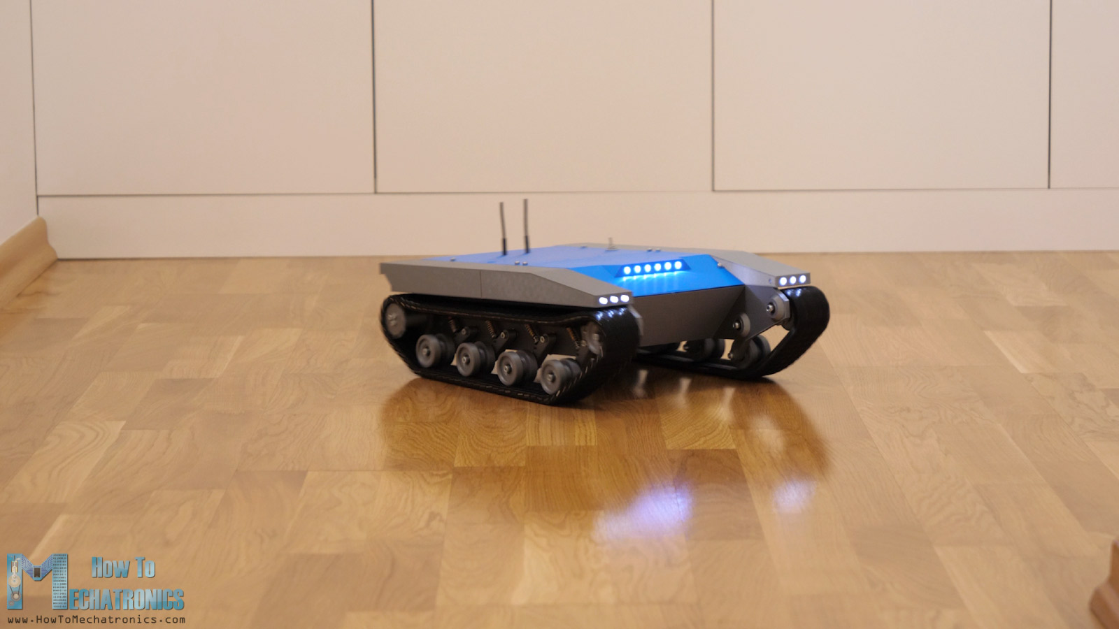
To be honest it is really fun driving this thing around, especially with the LEDs flashing and making burnouts or donuts.
However, the fun didn’t last that long as once I took it outside, it stopped working really quickly. The problem is the underpowered motors, that’s right, but also the design of the track links. Dirt easily gets stacked in them where the sprocket teeth go.
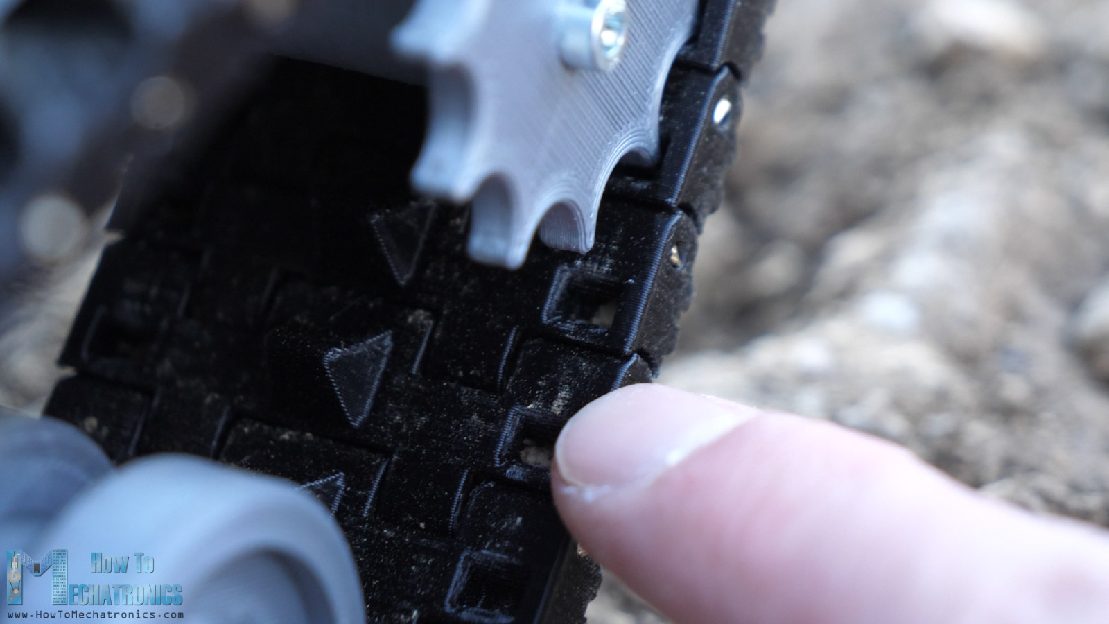
So, I redesigned them to have an opening at the other side so that the dirt can pass through them. I also made the sprocket a little smaller, by offsetting it by 0.2mm, in order to have a looser fit between it and the track.
I reassembled everything with these updates and the platform was now capable of driving outside. Though the underpowered motors were again a problem. The platform was getting stacked from time to time and couldn’t go uphill. So, my suggestion would be to get not more than 500 RPM motor, and to be a stronger one with at least 1A or 2A rated current.
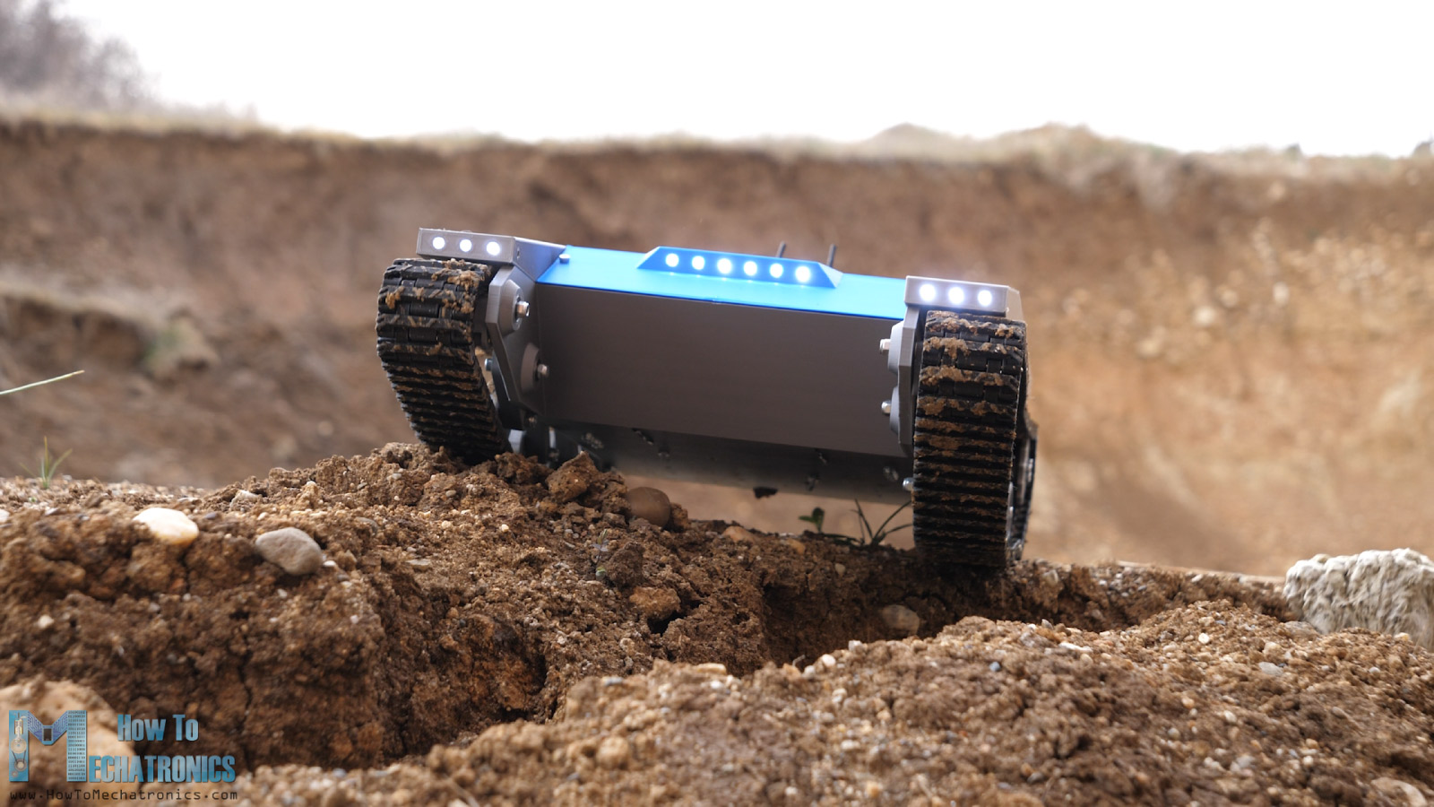
I actually tried the platform with stronger motors. They were just 20 RPM which was obviously too slow for having fun and doing donuts, but the platform now was just like a real tank. It could literally go anywhere.
The 20 RPM motors were powerful enough to climb any obstacle. They were really slow, but maybe they are fine for some specific applications. My suggestion would be if we need slower speeds to go for motors with around 50 RPM, and for faster speeds, around 500 RPMs.
I hope you enjoyed this video and learned something new. Feel free to ask any question in the comments section below and don’t forget to subscribe for future updates and and check my Arduino Projects Collection.
Hi Dejan. Your project is very nice. Thank you for your efforts. What percentage of print density do you recommend for 3D prints?
Hey, thanks! I printed everything around 30% infill. Maybe for the big base parts you could go lower in order to safe some time.
Hello
The PCB board you had made for the tank, do you have a list of parts that need to be soldered to the board.
Thank you
Hey, please use the circuit schematic to make a list of all parts needed for the PCB board.
Hey Dejan!
Is there anywhere a BOM for the PCB? Because I´m not that well at electronics at the moment, so I would need to know which parts I should order.
And is it possible to run the tank with an Spektrum RC System?
Thank you 🙂
Hey,
Please use the circuit schematic to see and make list of all components needed for this project.
I don’t have experience with an Spektrum RC system, but if you can integrate it with an Arduino controller then yes, it could be used. But I cannot tell for sure.
Cheers
My son and I have been having lots of fun working on this project. You clearly put lots of time, effort, and skill into the engineering of this tank. Currently there are two issues I’m hoping you can help us figure out.
1. The Flysky FS-i6X appears to only be transmitting on 6 channels. I’ve confirmed this by looking at the Display of the channels on the controller. I can see channels 1 through 6 responding, but when I try to flip the switches at the top of the controller (SWA/B/C/D) there is no change on the display of the controller. I suspect this is because the receiver that came with the controller is only 6 channels. I’ve also confirmed by modifying the Arduino code to output the values to the serial monitor and I can see channels 0-5 changing values as expected but the values for channels 6 or 8 do not change. Does this mean I need to get a different receiver to go with this controller?
2. For the DRV8871 motor controllers, in the pictures / video I don’t see wires being run to the 12V on either of the controllers. At the moment, when I hook up the PCB to the Arduino and the DRV8871 to the PCB, the motors aren’t moving. Based on everything I’m reading on this controller, I need to provide 12V to the board on the power connectors next to the wires going to the motor. Can you confirm if there is something about how you’ve designed this that is somehow providing the 12V to the motors via the pins connecting to the PCB or do I need to go ahead and provide power to each of these boards as well?
Thank you!!
Glad to hear it you are having fun!
1. Yes, the Flysky FS-i6X is originally has 6 channels but there your can easily enable to have 10 channels. Search on YouTube for a tutorial “10 channels on Flysky FS-i6x”.
2. Each DRV8871 motor controllers is already connected to 12V on the PCB. You just need switch on the “ON/OFF” button each motor controller should get 12V at the “Vm” pin. I’m not sure what could be the problem.
Thank you for the response!!
1. I found the tutorial and was able to get the additional channels working, thank you!
2. I got my multimeter out and yes I see now where it’s getting the 12V to the motor controllers.
This brings me back to what I believe is related to why the motors are not working. I’ve been troubleshooting this further and I’m getting stuck.
I’ve confirmed by making some minor modifications to your Arduino code to output values to the serial bus for each of the channels being received by the Arduino via the Receiver / iBUS. When I have the FS-IA6B directly connected to the Arduino including 5V / Ground, everything seems to look correct. However, when I try it with the PCB and power everything from a battery, the Arduino doesn’t seem to be able to read from the FS-IA6B (it’s outputting all zeros as if the receiver isn’t connected).
Here’s what I’ve done so far to try and troubleshoot this:
– I’ve confirmed the 5V going to the receiver is the correct voltage by adjusting the potentiometer. I’ve also periodically re-checked this to make sure the voltage hasn’t drifted with all of the handling I’ve been doing.
– The receiver powers up and the controller beeps to acknowledge it is connected to the receiver
– The Arduino is powering up and I’m able to see the output from my custom code by connecting a PC into the TX0/RX0 pins on the PCB which is where it’s showing all zeros for all of the channels it’s attempting to read
– I’ve confirmed continuity from the pins on the header on the PCB where the FS-IA6B is connecting and confirmed those are going into the correct ports on the Arduino.
– I’ve tried disconnecting the PCB from the Arduino and jumping the necessary pins between the PCB and the Arduino
None of the above changed anything with regards to the output of the values except when I connect 5V / GND / Signal directly to the Arduino.
One thing I want to make sure I mention is the exact Arduino I’m using is ELEGOO Arduino Mega. I have another SainSmart Arduino Mega that I’ll try right now to see if it produces any different results.
Update / not really an update.
I tried a different Arduino Mega board (SainSmart) and same results.
At this point I suspect something went wrong when I soldered the parts onto the PCB board. I’m noticing some weird behavior in the voltages on the 5V connections.
At one point, I observed the voltage measured at the 5V header pins to be ~2.5 volts when the FS-IA6B was also connected at its respective header pins. After disconnecting the Arduino from the PCB, I then observed the voltage jump from 5V to 6V when connecting the FS-IA6B.
I’m not an expert with electronics by any means so I might just take one of the extra PCBs (minimum order was 5) and try it again and make sure I’m extra careful soldering the pieces to the board.
Any thoughts on how to confirm / areas to check to see if I maybe used a wrong part or shorted something?
Thank you!!
Hey Keith, so the problem is definitely the FS-IA6B iBUS communication. Using the same PCB, try loading simple codes from the Library example, or try examples from other tutorials about Arduino and the FS-IA6B and try to get it right the communication and then change the tank code appropriately. Also, if you cannot get it working with the iBus maybe you can get it working with individually connecting each channel from the receiver to the free digital pins on the PCB. Then using the pulseIn() function read the incoming data. Search for other tutorials for this matter.
Hi Dejan, I’m nearly done making this and plan to use your transmitter that I made (and works great).
I noticed that in this design it doesn’t appear, as far as I can tell, as if the CE and CSN pins are connected to anything. I thought those were required for the NRF24L01 to work? Is this just a miss or is there a way to control the NRF24L01 without those pins?
Hey, I’ve just checked the PCB, and it’s true, the CE and CSN connections are missing. I must have missed them when making the PCB. But luckily, it’s not a big deal, you have available digital pins on the PCB, from D22 to D99. You can use any of them for the NRF24L01 CE and CSN pins. Just use connect them those pins together under the PCB with a wire or something like that.
Hey Dejan!
I wanted to order your PCB for the tank using PCBWay. When I tried to order your PCB for the tank then PCBWay asked me about the order of the layers in your PCB for the tank. I was wondering if I need to put the PCB layers in a certain sequence, or can I skip the layer sequence when I order from PCBWay?
Thanks.
Hi, you should select 2 layers. For some reason when uploaded the Gerber file it pulls info that it has 4 layers, but there are only 2 layers. So just select 2 layers and you are good to go.
Hello
I have a problem with the 5v
I created the board with the components but I have a problem I only find 12v even adjusting the small potentiometer nothing happens
anyone have a solution
Looking forward to
Hi,
Make sure you have everything connected properly. That simple circuit for stepping down the 12V to 5V should work.
I can only give you a tip that these small potentiometers sometimes need a lot of turns to make an effect on the voltage output.
Hello Everyone,
Awesome project.
I was wondering does anyone know what software to use to make the schematics shown in the sections “Electronics – Robot Platform Circuit Diagram”?
Thanks a lot.
Hi,
I think this is a great project, thank you for sharing all your very clever, hard work. I started by printing the track linkages which have come out perfectly. I then wanted to print the next time consuming parts, the body but when I loaded robot chassis-section 2 into Cura I was unable to slice as Cora said review settings that model fits build volume, assigned to enabled extruder, are not all set as modified meshes. I’m not sure what all that means unfortunately. The chassis just fits the build plate of my Ender 5 and I haven’t adjusted anything so can you help me so I can continue printing ?
Cancel that, it’s having a raft that makes it oversize. Once removed it fits and will slice 🙂
What type of filament did you use to print the parts ?
I used PLA.
we missed hearing your voice 🙂
😀
Hello Dejan.
Congratulations on your cool projects.
I liked the project TANK – Tracked Robot Platform. I would like to do something similar based on your project. However, I am having trouble opening the files you have made available for download. Could you help me or send them to my email?
Thank you.
Hi there and thanks. What kind of trouble you have opening the files? They should work. They are in RAR file and maybe it takes a bit time to be opened.
Hello!
I am looking at building this, but I have a few questions.
1. Is the motor linked for Amazon the recommended motor, or the one used in the video?
2. How much 3D printer Filament was used to make the 3D printed components?
Thanks for your consideration
Hi, the motor in the link is the recommended one. Like I said, you should choose the RPM of the motor. My suggestion is anything from 50 to 500 RPM.
Hello Dejan.
I would like to thank you for the efforts you made in this awesome project. You inspired me to build my own projects.
Thanks.
Hey, I’m glad to hear it, thank you!