In this article, we will take a look at my new updated version of the cycloidal drive that I made in the previous video, with 19:1 reduction ratio and see how it performs made with CNC machined parts versus made with 3D printed parts.
I will explain how I designed and assembled this cycloidal driver, as well as test its accuracy and load capacity, driving it with both NEMA17 and NEMA23 stepper motors.
You can watch the following video or read the written tutorial below.
Cycloidal Drive Overview
In my previous video I already explained in details what is cycloidal drive and how it works, so I would suggest checking that video out in case you are not familiar with cycloidal drivers. Real quick, a cycloidal driver is a unique type of gearbox, or speed reducer which provides very high reduction ratio with a compact but robust design.
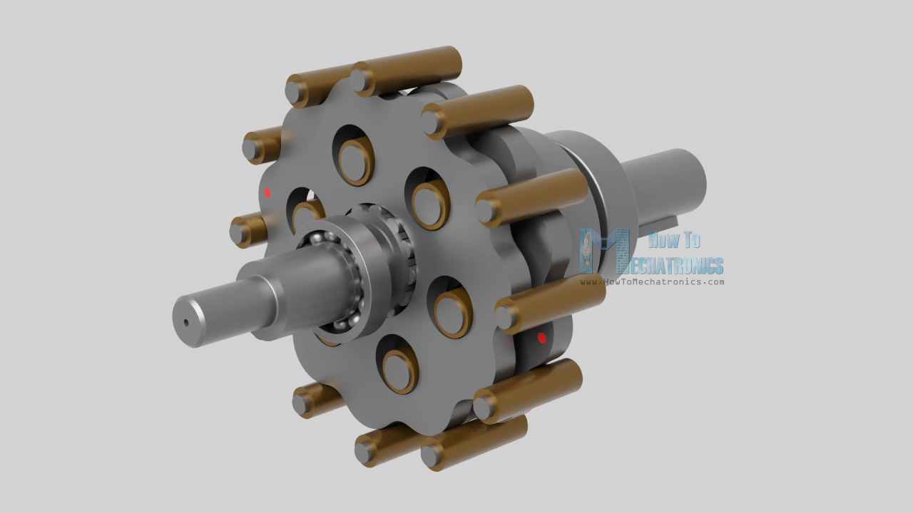
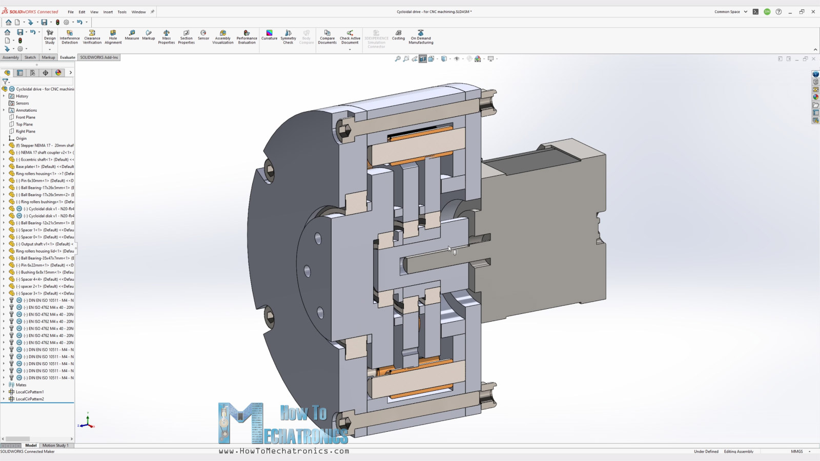
A cycloidal drive is composed of five main components, a high-speed input shaft, an eccentric bearing, two cycloidal disks, a ring gear with pins and rollers and a slow-speed output shaft with pins and rollers.
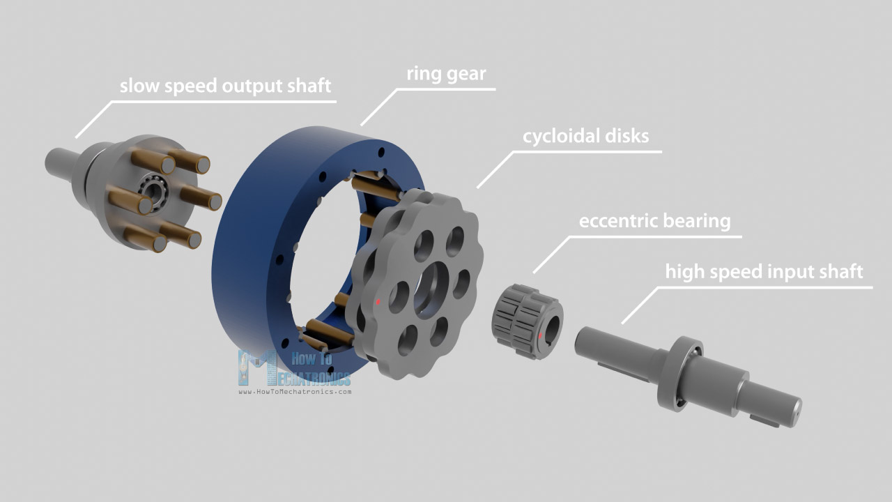
The input shaft drivers the eccentric bearing, and the eccentric bearing drives the two disks around the internal circumference of the ring gear housing. The eccentric motion makes the cycloidal disk teeth or lobes engage with the rollers of the ring gear housing in a way that they produce reverse rotation at a reduced speed. The reduction ratio depends on the number of pins on the ring gear.
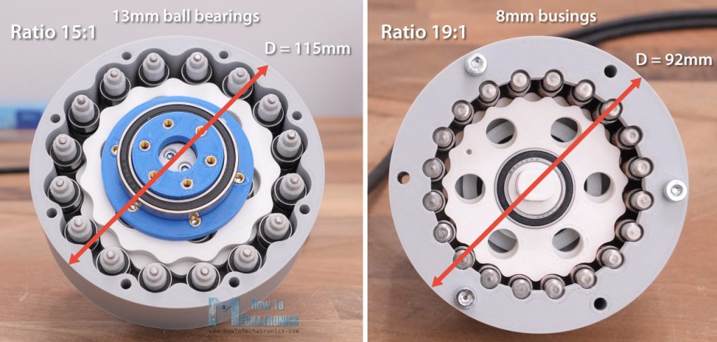
Again, you can find more detailed explanation in my previous video, as well as see the 3D printed prototype that I made for that video. It had 15:1 reduction ratio with 115mm diameter.
Now. for this build, I wanted to increase the reduction ratio but at the same time make the cycloidal driver more compact. To achieve that, instead of using ball bearings as rollers, I will use bushings with much smaller diameter.
The rollers diameter is actually the most crucial dimension because together with number of pins, they define the size of the gearbox. Let’s see why is so by explaining the processes I used for designing this cycloidal drive.
Designing the Cycloidal Drive
So, first I defined the diameter of the rollers to be 8mm, as that was the dimension of the bushings I could order easily. Then I wanted to have 19:1 reduction ratio, which meant that the ring housing needed to have 20 rollers. So, I draw a sketch with these 20 rollers with 8mm diameter around circle.
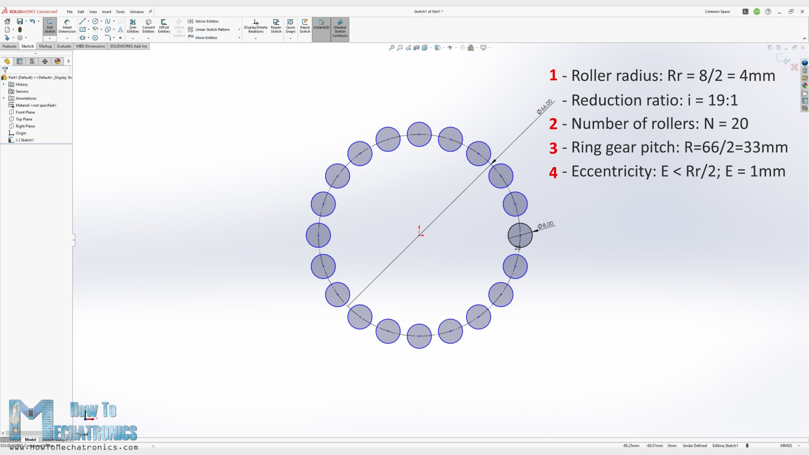
Now according to these two inputs, I was able to determine the minimum size of the ring gear pitch diameter. This value, together with the eccentricity value which should be smaller than half of the roller diameter, make up the four main input parameters that are used for generating the shape of the cycloidal disks.
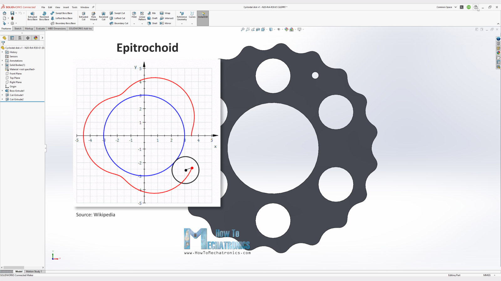
The cycloidal disk profile comes from a Cycloid, which is a curve traced by a point as it rolls along a straight line without slipping, or actually its variation, Epitrochoid, which is a curve traced by a point rolling on a circumference of a circle and it is at a distance from the center of the exterior circle.
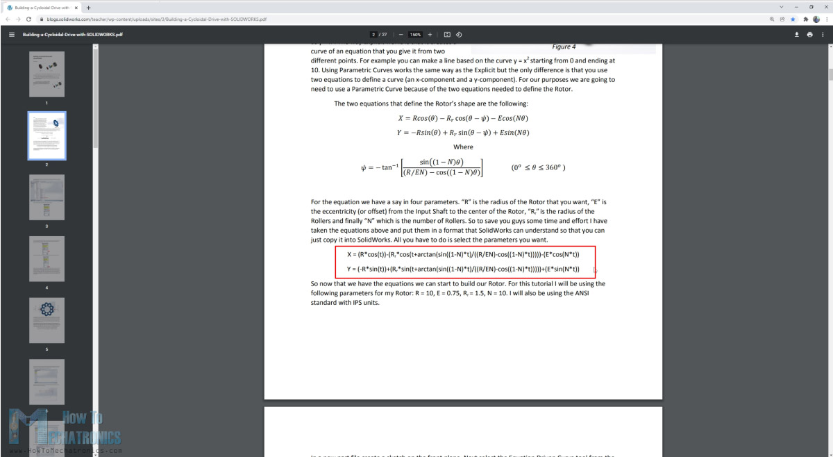
For drawing such a curve, we can use the following parametric equations which can be found in a document written by Omar Younis for the SOLIDWORKS education blog.
Now I will show you how I used these parametric equations for making the cycloidal disks using SOLIDWORKS and its Equation Driven Curve tool.
Here’re the equations:
Equations by Omar Younis
N - Number of rollers
Rr - Radius of the roller
R - Radius of the rollers PCD - Pitch Circle Diameter
E - Eccentricity - offset from input shaft to a cycloidal disk
x = (R*cos(t))-(Rr*cos(t+arctan(sin((1-N)*t)/((R/(E*N))-cos((1-N)*t)))))-(E*cos(N*t))
y = (-R*sin(t))+(Rr*sin(t+arctan(sin((1-N)*t)/((R/(E*N))-cos((1-N)*t)))))+(E*sin(N*t))
===================
Values for this DIY Cycloidal Drive:
i = 19:1
N - 20
Rr = 8/2 = 4
R= 66/2 = 33
E = 1
x = (33*cos(t))-(4*cos(t+arctan(sin((1-20)*t)/((33/(1*20))-cos((1-20)*t)))))-(1*cos(20*t))
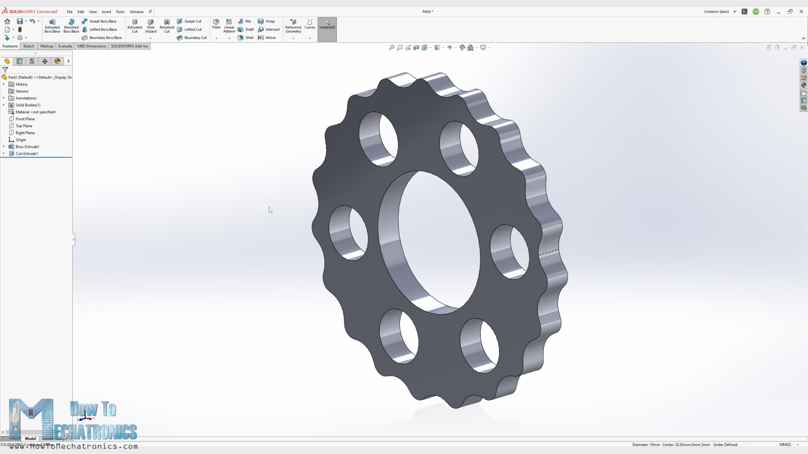
y = (-33*sin(t))+(4*sin(t+arctan(sin((1-20)*t)/((33/(1*20))-cos((1-20)*t)))))+(1*sin(20*t))Code language: JavaScript (javascript)We can easily generate the cycloidal disk shape by inserting the two parametric equations in place. Of course, we should use our parameters in the equations appropriately. As for the “t” parameters, we should use the value from 0 to 2*Pi.
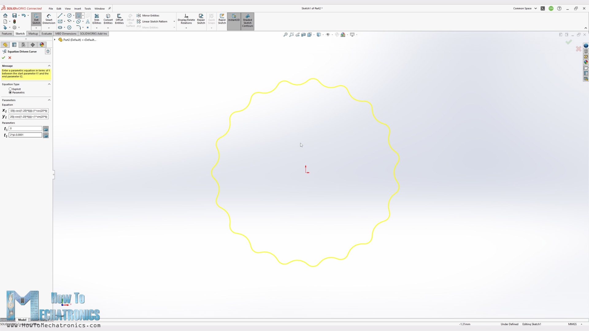
Though, we should note that we need to use a slightly smaller value than 2*Pi, in order the curve to be generated. This will generate the curve with a little gap which can be than easily connected with a spline.
Then we can simply extrude the profile, and make the holes for the eccentric bearing and the output pins. The diameter of these output holes is equal to the pin rollers diameter + two times the eccentricity. In this case that’s 8 + 2*1 = 10mm diameter.
Nevertheless, so let’s build this cycloidal drive now and see how it works in real life, both with CNC machined and 3D printed parts.
3D Model and STL Files Download
You can find and download the 3D model of this Cycloidal drive as a STEP file, as well as explore it in your browser on Thangs:
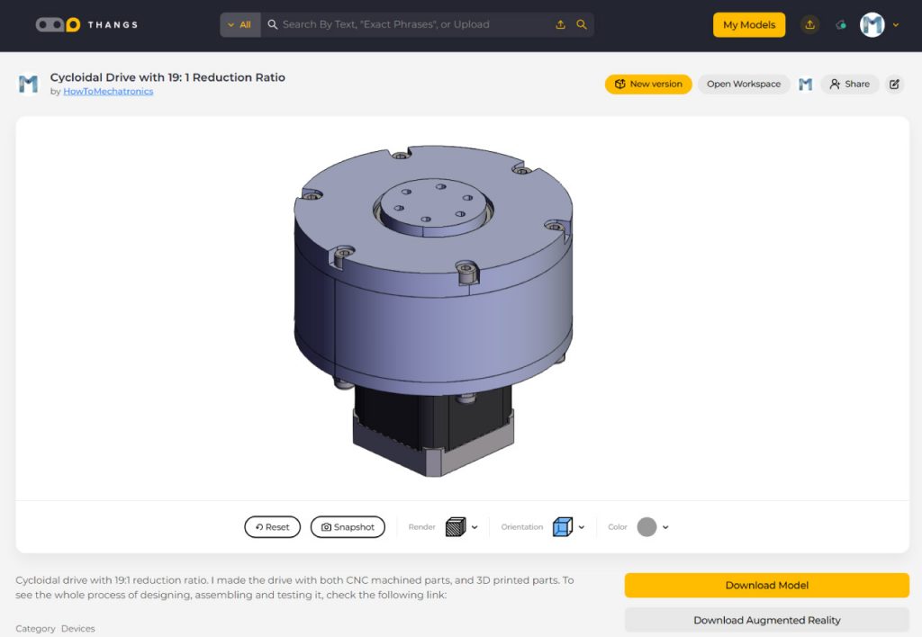
Download the 3D model .STEP file from Thangs.
As for the STL files which are used for 3D printing the parts, you can download them here:
Here you can also download the SOLIDWORKS files:
Drawings:
I used these drawings when ordering the CNC machined parts.
Ordering the CNC Machined Parts
I ordered the CNC machined parts from PCBWay. Along their PCB manufacturing services, they also offer CNC Machining, 3D Printing, Sheet Metal Fabrication and Injection Molding services.
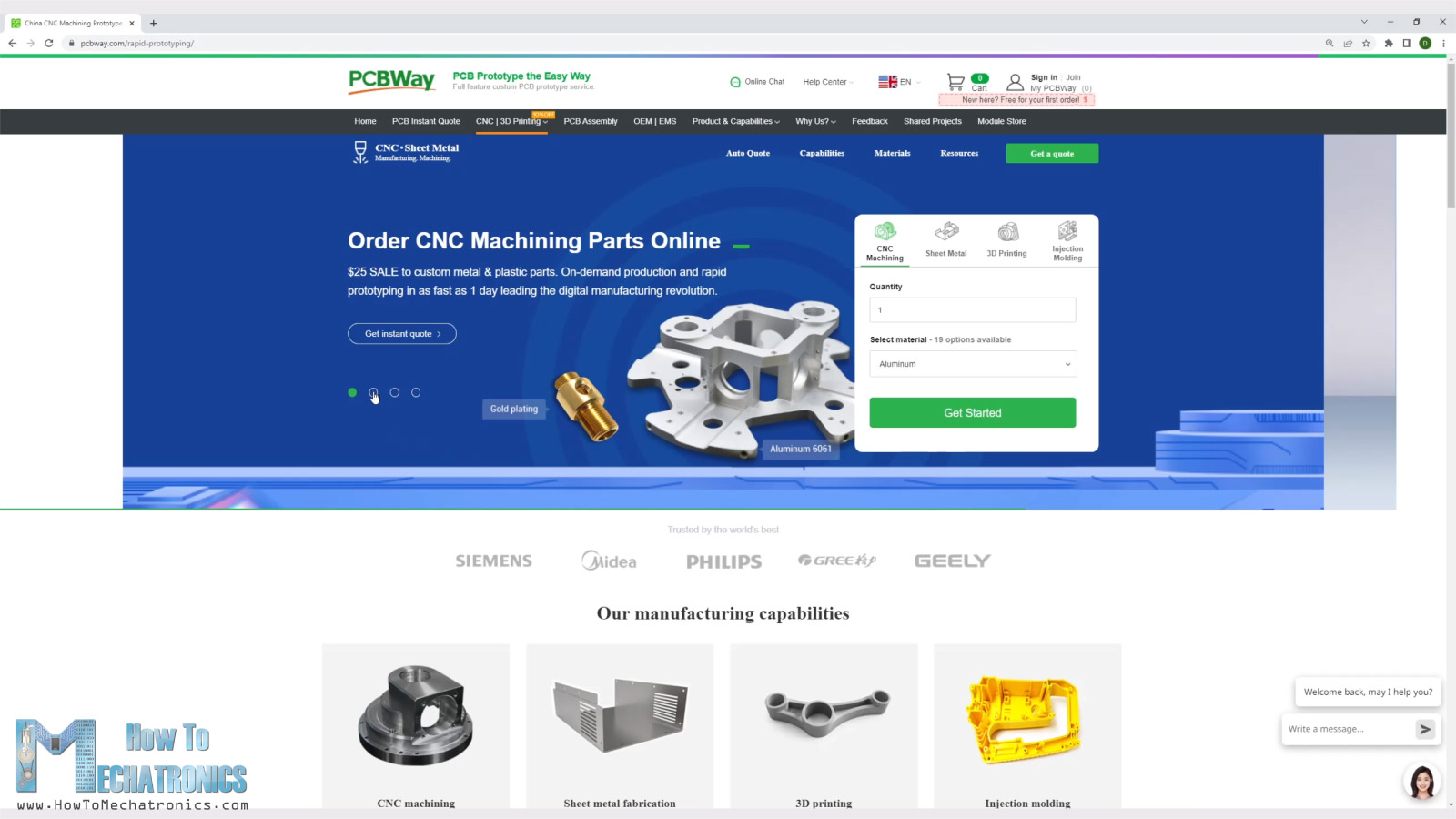
Ordering the parts is super easy. We just have to upload the 3D model and select the material for the part. They have pretty much any material available. I chose Aluminum for most of the parts, except for the cycloidal disks which I wanted to be made out of stronger material, so I chose stainless steel for them.
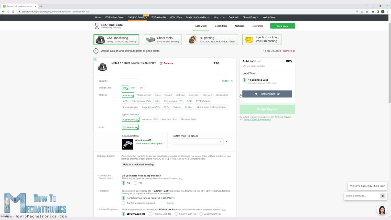
We also have the option to choose various surface finishes, like anodized, brushed, spray painting and so on, as well as choose surface roughness and tolerance. For those parts that I needed tighter tolerances than the standard one, I also included drawings which contained the specific tolerances that I required.
We can add multiple parts and request a quote for each of them in a single order.
The parts arrived within the estimated time and well packed, each item separately protected.
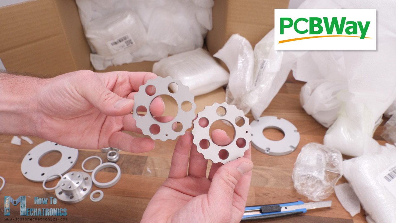
I must say it’s quite satisfying to have something that you have designed manufactured in metal. The parts look great and everything is exactly the same as in the design. Make sure you visit PCBWay website to learn more about their services.
Nevertheless, for the 3D printed version, I made the parts myself using a PLA material. When 3D printing the parts, it’s important to use the Hole Horizontal Expansion feature in your slicing software.
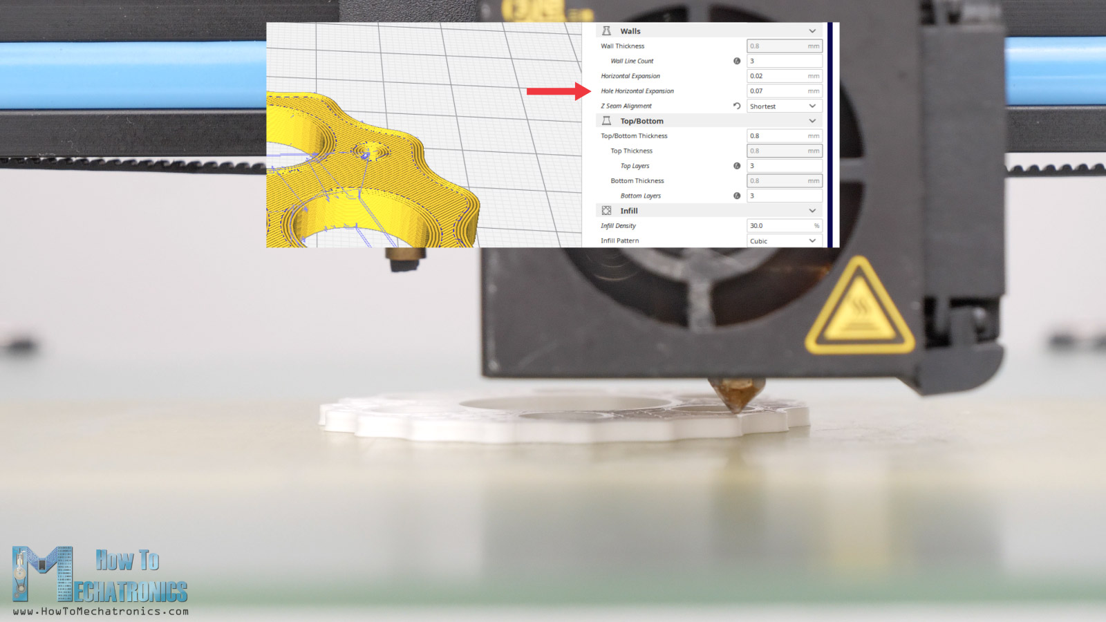
Usually, the holes of 3D printed parts are smaller than the original size, so with this feature we can compensate that and get more accurate dimension. I set mine to 0.07, and the Horizontal Expansion feature which compensates for the outer dimensions of the parts to 0.02mm. Of course, you should do some tests prints to see what values will give you the most accurate result on your 3D Printer.
Assembling the Cycloidal Drives
All right, so let’s move on with assembling the cycloidal drives. Here I have all of the parts. I will start with assembling the CNC machined version first, and then 3D printed one.
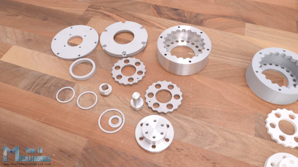
Here’s a list of all components needed for assembling this cycloidal drive:
- 6mm Steel Cylinder Rod …………………..…. Amazon / AliExpress
L=30mm x20 pcs; L=22mm x6 pcs for one drive - 8mm Bushings ………………………………………. Amazon / AliExpress
L=20mm x20 pcs; L=15mm x6 pcs for one drive - Ball Bearing 35x47x7 6807-2RS – x2 …. Amazon / AliExpress
- Ball Bearing 17x26x5mm 6803ZZ x2 …. Amazon / AliExpress
- Threaded inserts ………………………..………. Amazon / AliExpress
- M3 and M4 bolts from your local hardware store – I will include a complete list of bolts needed for this project in few days
Disclosure: These are affiliate links. As an Amazon Associate I earn from qualifying purchases.
I started with securing the shaft coupler on the NEMA17 stepper motor. The shaft coupler should be at a distance of 2mm from the motor front plate, and we can easily secure it using two grub screws. Then we can secure the base plate to the stepper with four M3 bolts.
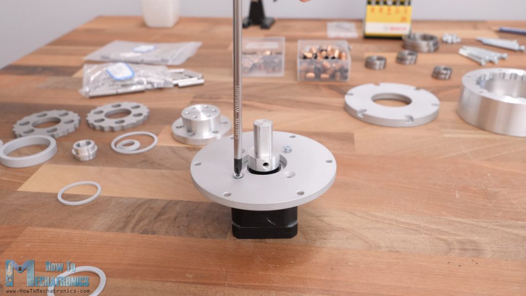
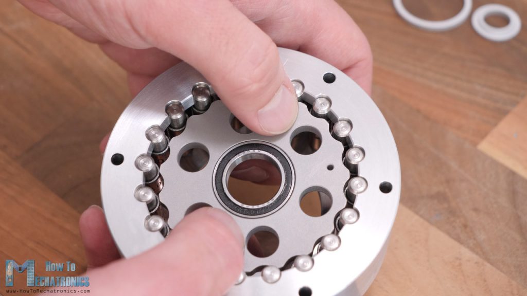
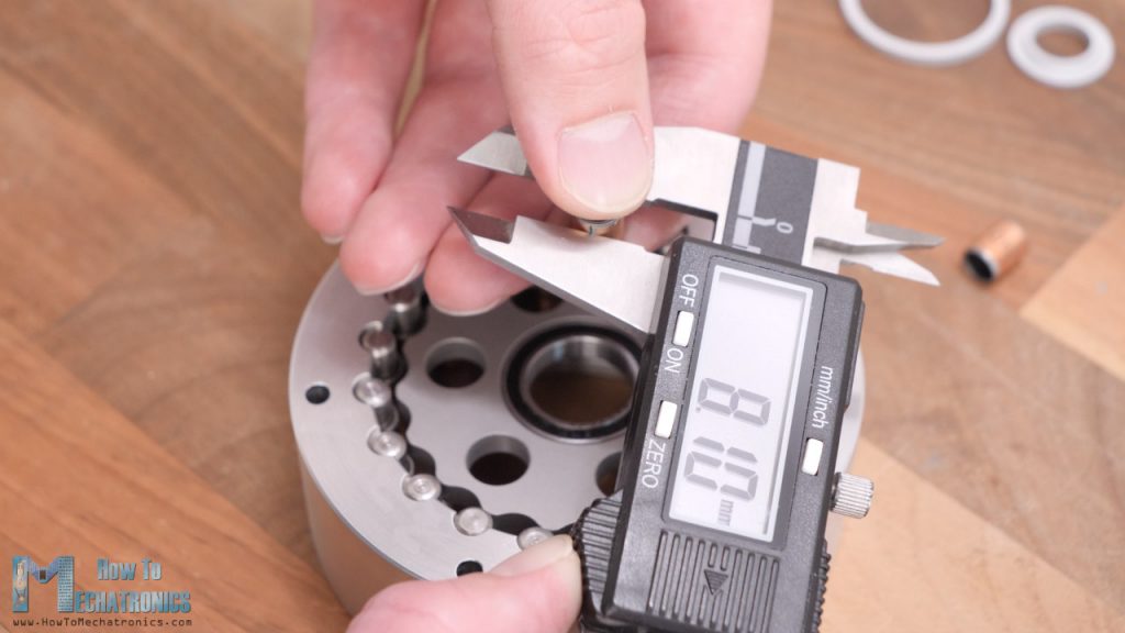
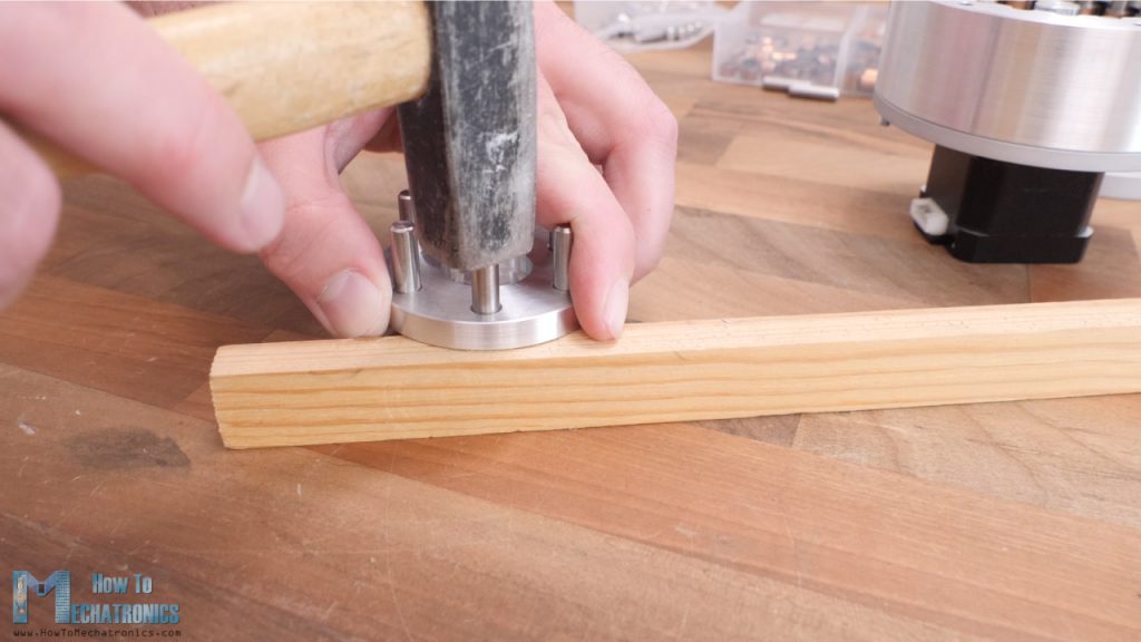
Next it goes the biggest part in this assembly, the ring gear rollers housing. Here we need to install the rollers which in this case are bushings with 8mm diameter and should be 20mm long. However, I couldn’t find that dimension at the time of ordering so here I’m using two bushing with 10mm length.
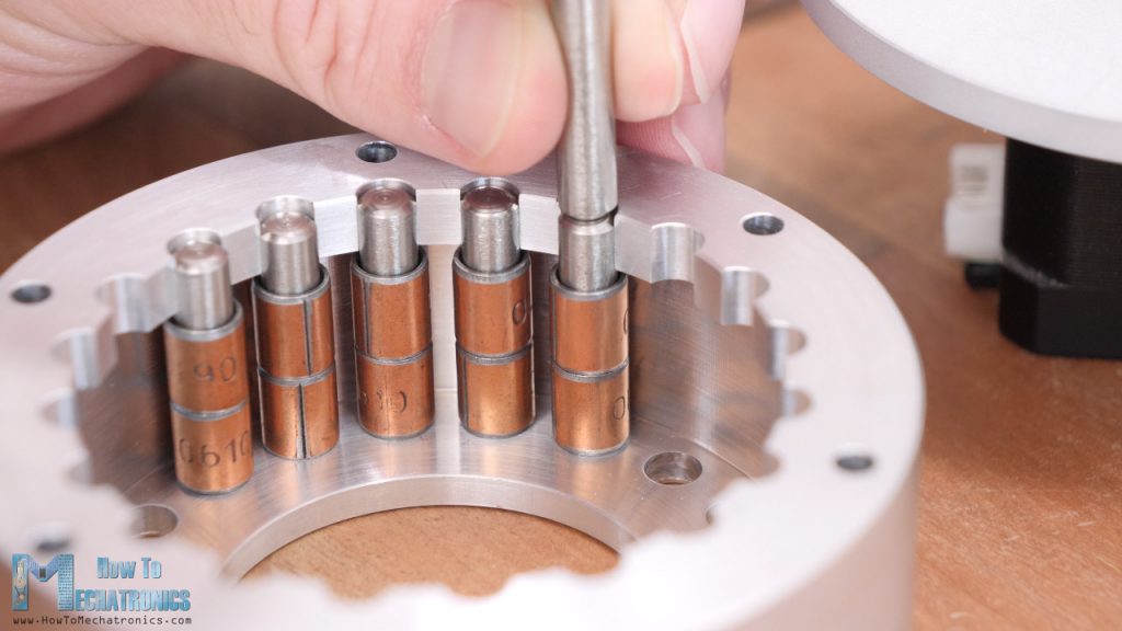
The pins on which these bushings are installed are 6mm in diameter and have a length of 30mm. The holes at the bottom of the housing are dimensioned to make a tight fit with the pins so that they stay firmly in place. Therefore, here we need to use some force in order to install them. Here they are, 20 rollers, which will give us 19:1 reduction ratio.
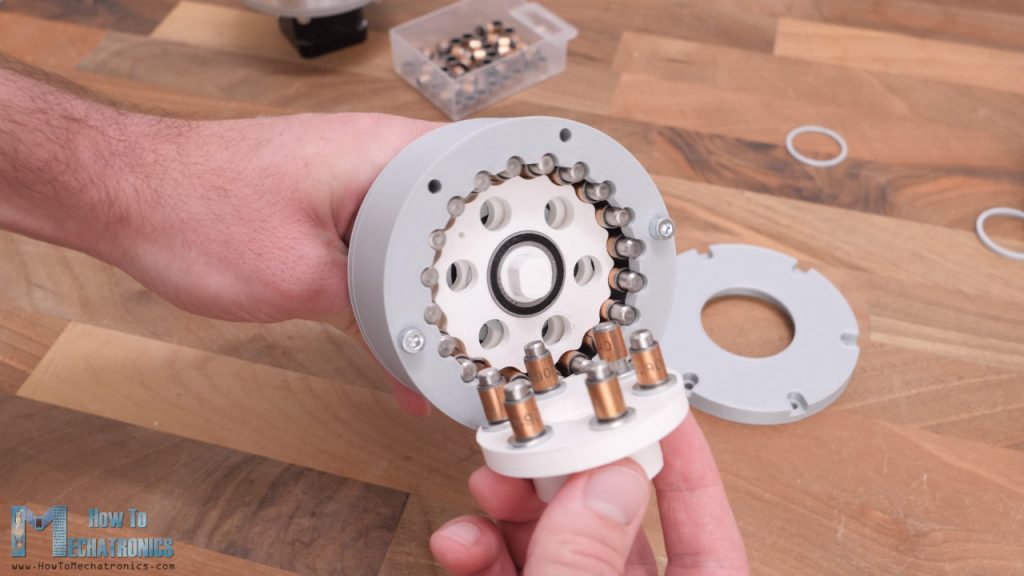
The ring gear housing goes on top of the base plate and here first we need to insert a distance ring which will hold the output rollers in place.
Next, we can install the eccentric shaft which goes on the NEMA17 shaft coupler. Actually, before we install it, we need to insert the two bearings with 17mm inner, and 26mm outer diameter.
You see, everything fits perfectly. I set the tolerances where the bearings go to be an interference fit in order the bearings to stay firmly in place. That’s why I had to use some force here in order to insert them.
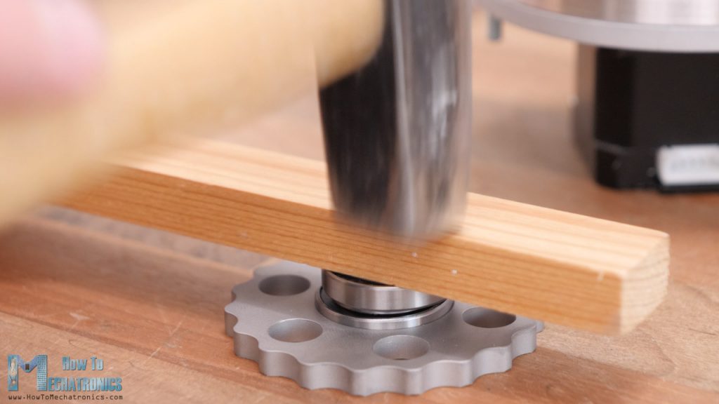
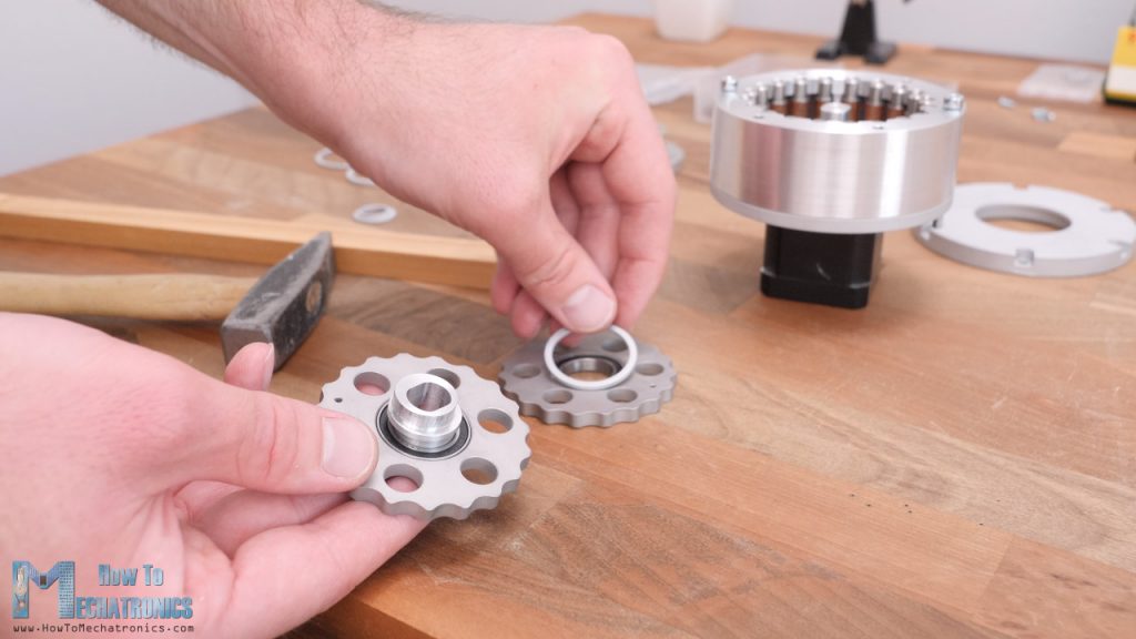
This assembly represents the eccentric bearing. Then, we can install the two cycloidal disks on the eccentric bearing. These are also interference fits and we need to use some force to install them. This fit was even tighter because I ordered the cycloidal disks to be powder coated by mistake, so they had a bit more material and the tolerance was not correct.
Nevertheless, we can also install a distance ring between the two cycloidal disks in order to keep the them in place in case the fit between the bearing and the disks loosen up.
We can then insert this assembly as a whole into the housing or one disk at a time. This fit, between the cycloidal disks and the ring gear rollers is crucial as it defines how well the drive will perform. As I was trying to make this fit as tight as possible in order the drive to have minimum backlash, I encountered a problem as the disk couldn’t fit it.
The problem was caused because I didn’t make any clearance, or offset to the cycloidal disk profile that I got from the parametric equations, and in addition to that, I ordered the disks powder coated which also increased their size. On top of that, the bushings that I had were not that good and had slightly bigger diameter than 8mm.
So, in order to solve this problem, I had to order new cycloidal disks, but I decided to try to remove some material off of the disk profile using a rotary tool. After some sanding, I was actually able to fit in the disk.
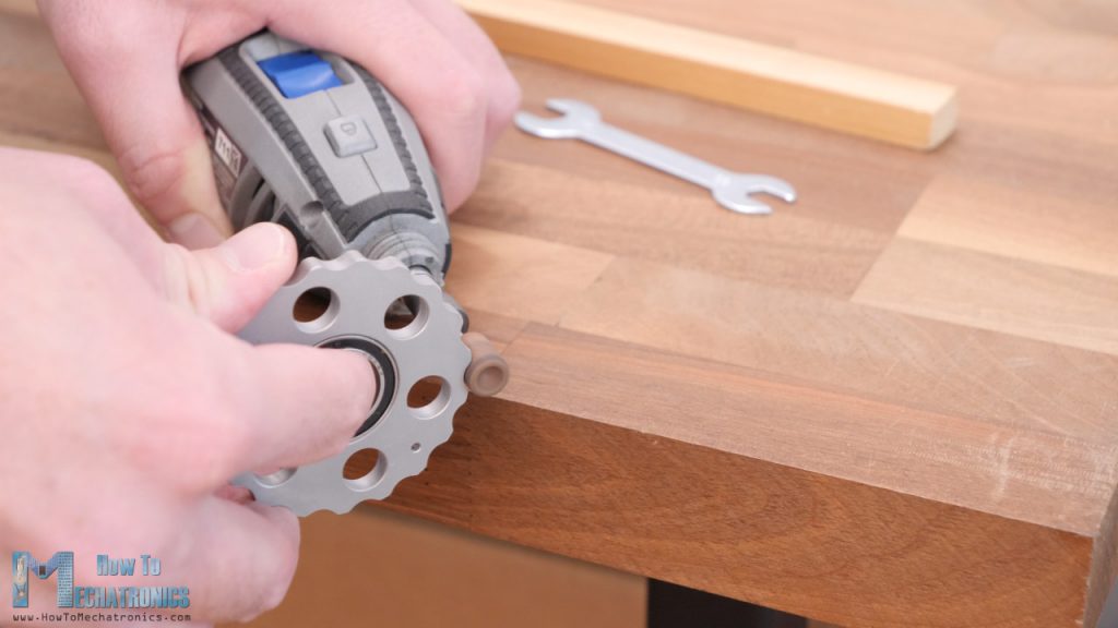
Of course, this is not the best solution, but we will see how it will perform.
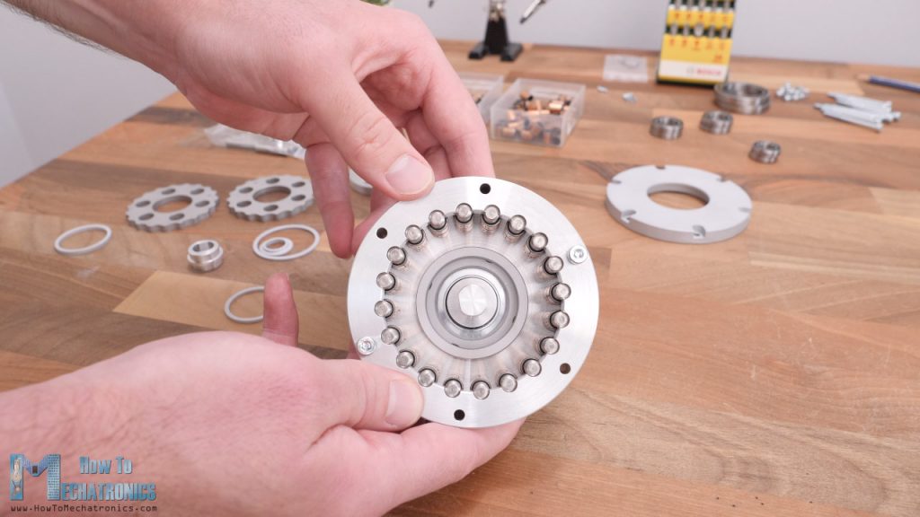
Nevertheless, when inserting the two disks in the housing, they must be placed 180 degrees out of phase.
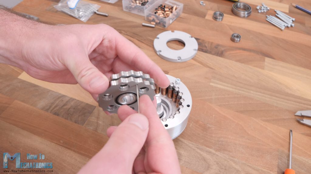
There’s a hole in the disks which can be used for positioning them correctly. We should flip one disk and alight the two holes. Once inserted, we can power up the motor and see how the cycloidal disks work in combination with the eccentric bearing and the ring gear rollers.
The cycloidal disks rotate with eccentric motion opposite to the input shaft, and with 19 times slower speed.
Now, this eccentric motion will be transferred to the output shaft through the six holes in the cycloidal disks. Here’s the output shaft. We need to secure six pins on which the bushings will go. The pins are 6mm in diameter and 22mm long. The holes on the output shaft are dimensioned to make interference fit so that they stay firmly in place when installed, and therefore we need to use some force in order to install them.
Once we secure the pins, we can insert the 8mm bushings. Here we need 15mm long bushings but at the time of making this project I couldn’t find that dimension so I used 10mm bushings but inserted some washers for compensation.
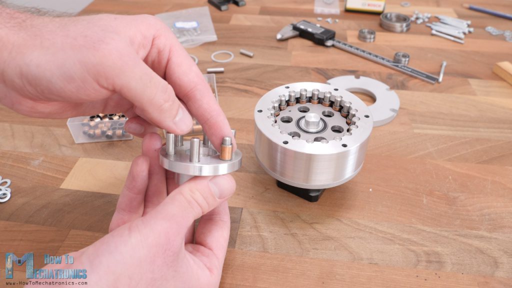
I actually used just one washer instead of two as show in the video. However, the included links for all components needed for this project are with the correct dimensions.
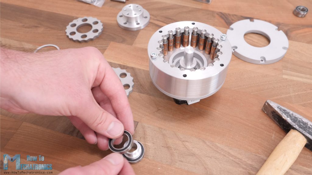
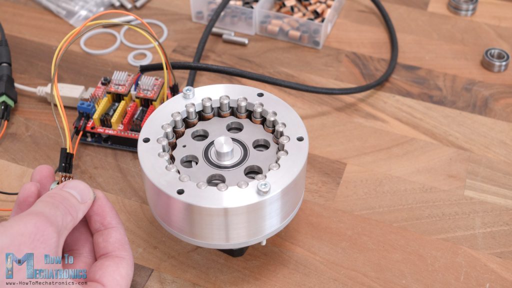
Before inserting the output shaft in place, we need to insert a distance ring and a bearing which will support both the input and the output shaft. Then we can just insert the output shaft into the cycloidal disks holes.
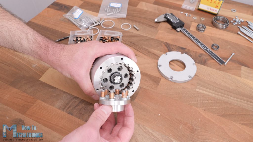
On the output shaft, we need to insert one more distance ring and a bearing with 35mm inner diameter.
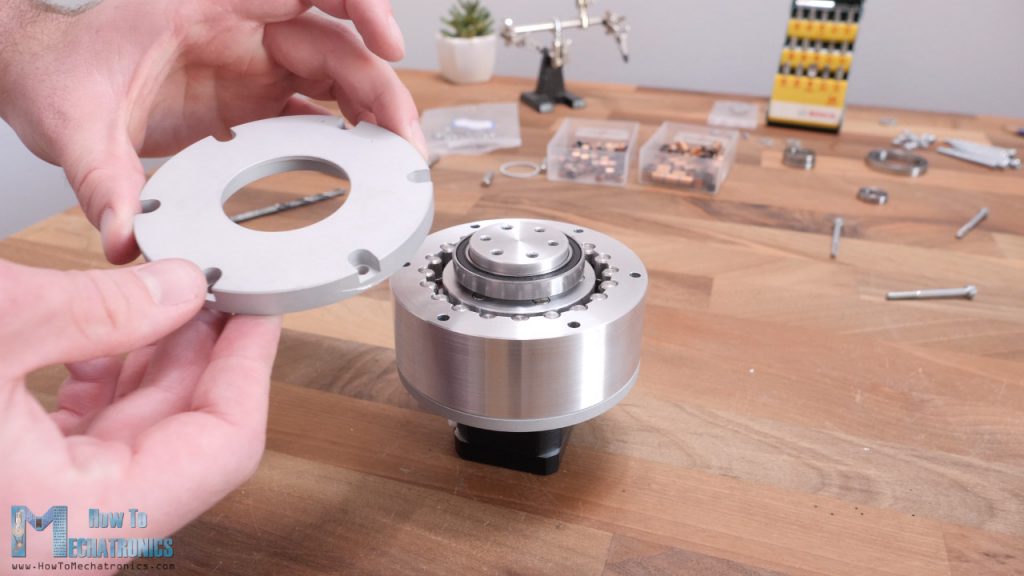
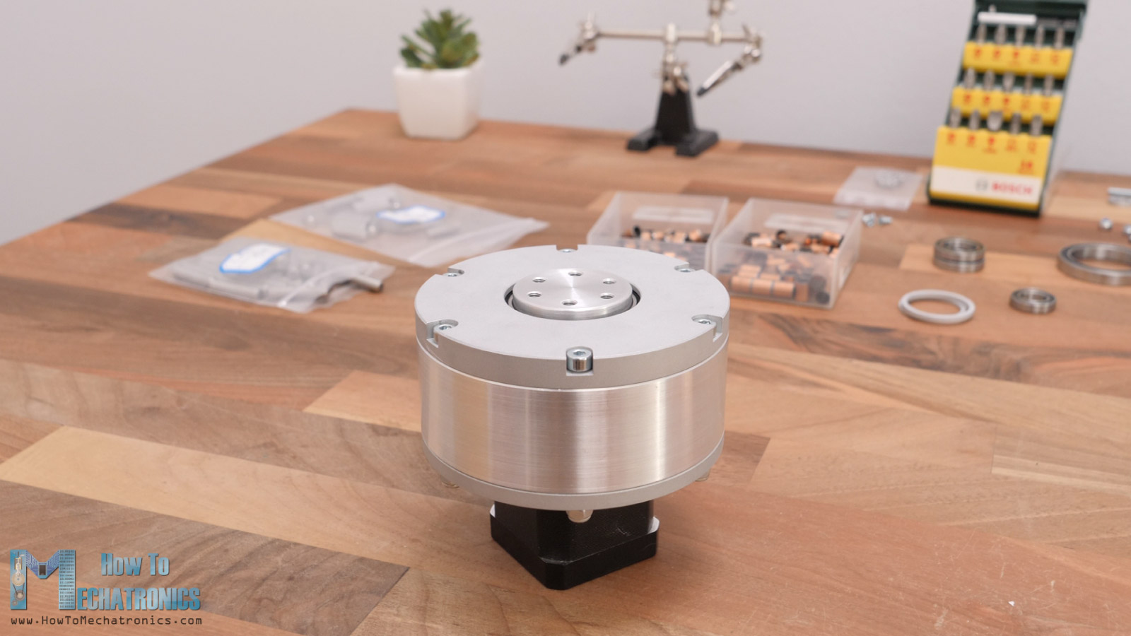
We can finally finish the assembly by inserting the housing lid on top of everything and secure it with six M6 bolts with 45mm length. And that’s it, the cycloidal drive is now fully assembled, I really like how it turned out.
Now, as for the 3D printed version, we can follow the exact same procedure for assembling it.
One additional step here is that we need to install some threaded inserts to the output shaft, so we can attach things to it.
Testing
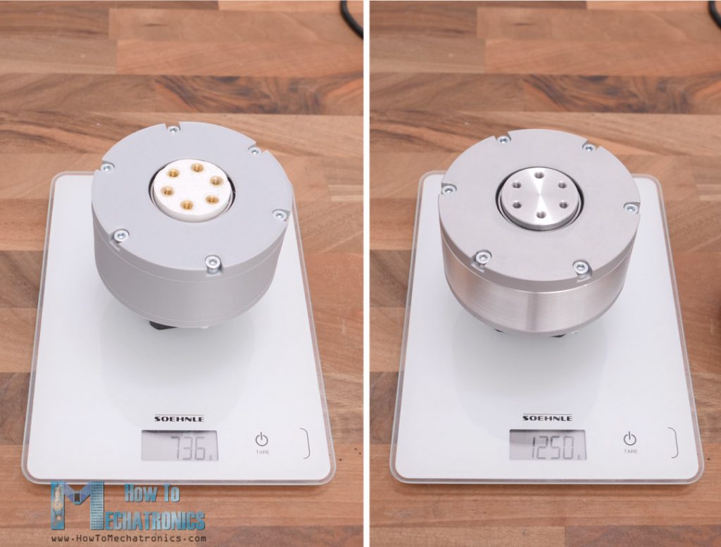
All right, so now that I have the two cycloidal drivers ready and it’s time to put them through some tests and see how they perform. A quick note before we see the tests, the weight of the CNC machined version is considerably higher that the 3D printed one.
Torque
I will start by testing how much torque these cycloidal drives can output. Here I put the two drives side by side and I’m measuring the force they can produce at a distance of 10cm.
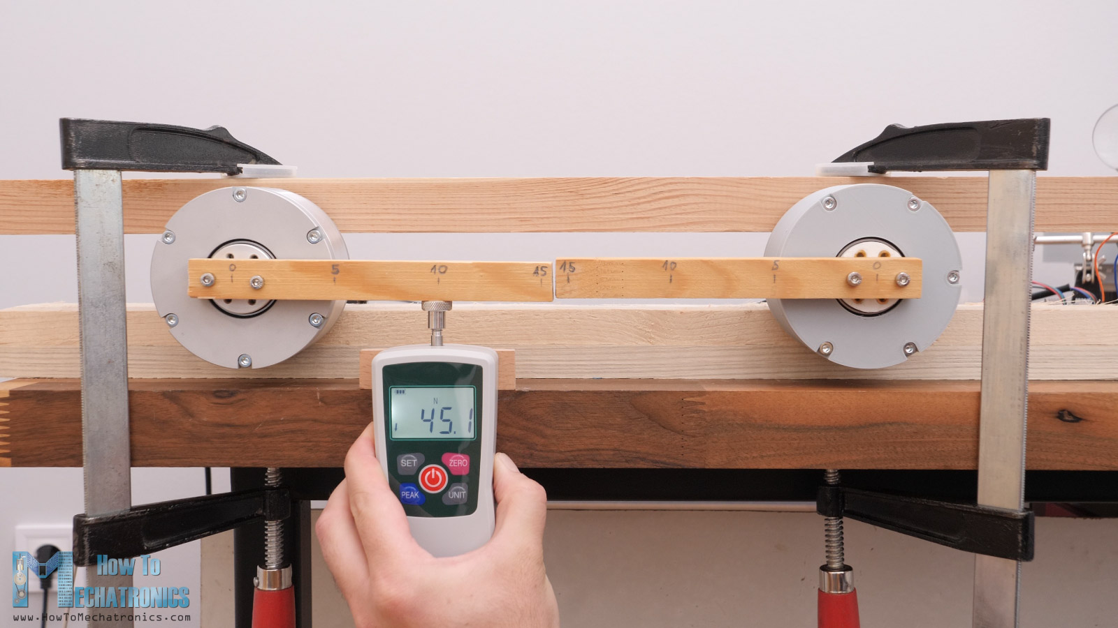
They both outputted a force of around 45N at a distance of 10cm, which translated to torque, it’s around 450 Ncm of torque. Though, the CNC machined one was giving a little bit higher and more consistent results.
On the other hand, these NEMA17 stepper motors are rated at 28Ncm which means that we’ve got around 16 times torque increase. That’s efficiency of around 85% considering that reduction ratio is 19:1, and in ideal conditions we should get a 19 times torque increase.
Nevertheless, let’s see how they will perform when we attach NEMA23 stepper motors to them. I designed the cycloidal drive so that we are able to use it with both NEMA17 and NEMA23 motors. However, in order to keep the design as compact as possible, the swap from NEMA17 to NEMA23 requires some work.
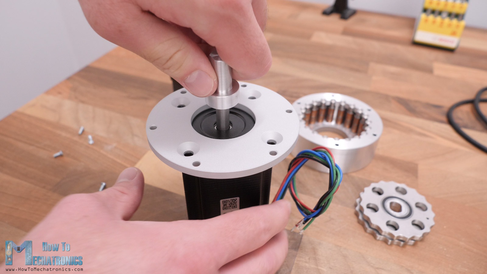
We have to disassemble some of the parts, and change the base plate to fit the NEMA23 holes. We also need to use another shaft coupler as the NEMA23 has a bigger shaft. So basically, we just need to change these two parts and put everything back together.
I changed the stepper motor to NEMA23 on the 3D printed version as well. Here, when I disassembled the driver, I noticed that the cycloidal disks have already started to show some wear.
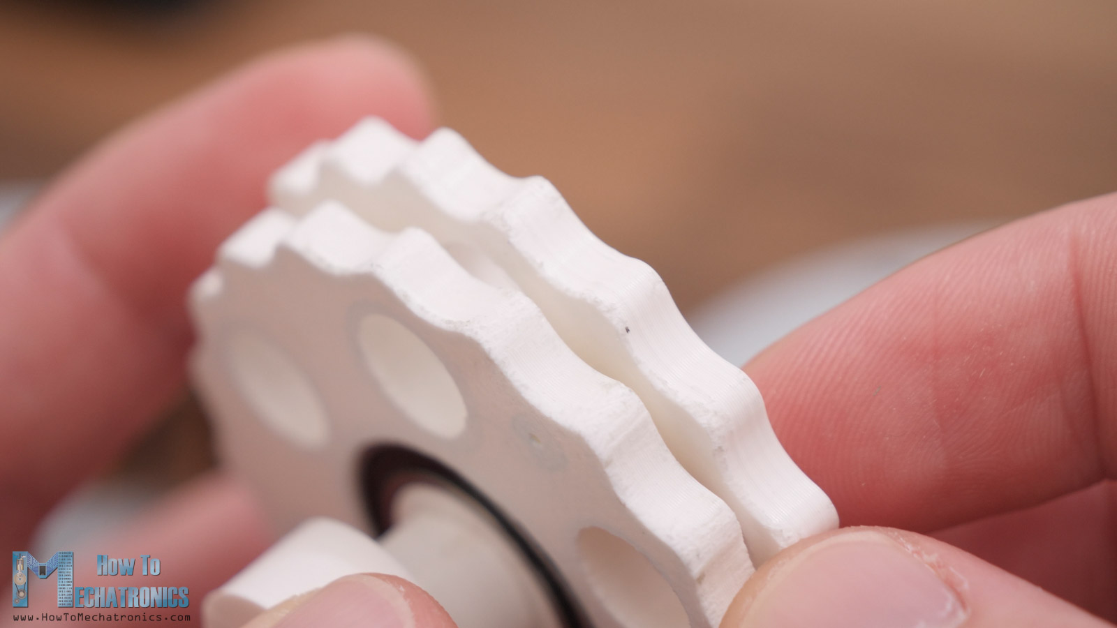
We can notice that the wear is more present on one side of the disks, and I guess that’s the bottom side of the parts when 3D printed. That’s due to the fact that the first couple of layers when 3D printing tend to extrude more filament.
Nevertheless, here are both cycloidal drivers with the biggest NEMA23 stepper motors that I had, in order to stress the drivers as much as possible.
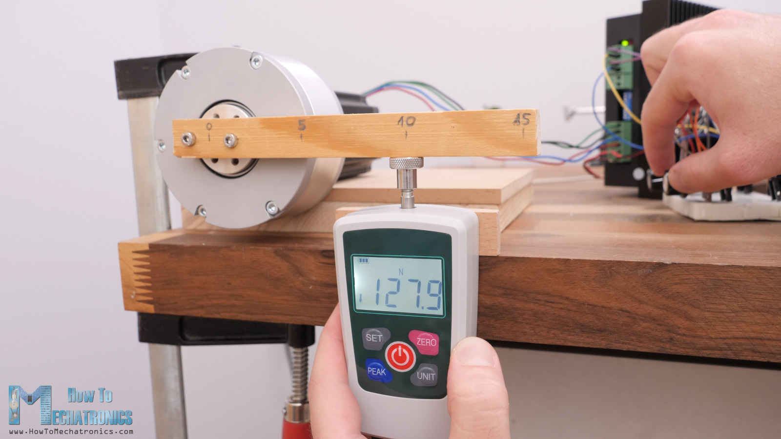
I initially started the test with the same 10cm stick that I already used, but I soon realized that I needed a longer one, as at just around 25% of the stepper motor power I already reached 130N at 10cm, and my Force meter can measure maximum of 200N. So, I had to increase the distance at which I measure the force in order to stay under 200N.
I attached a longer pine stick and tried to measure the force at a distance of 50cm. Well, the pine stick broke at a force of around 50N, as it’s actually quite weak material. So, I replaced it with a stronger, plywood stick, and I was able to measure the force at a distance of 50cm.
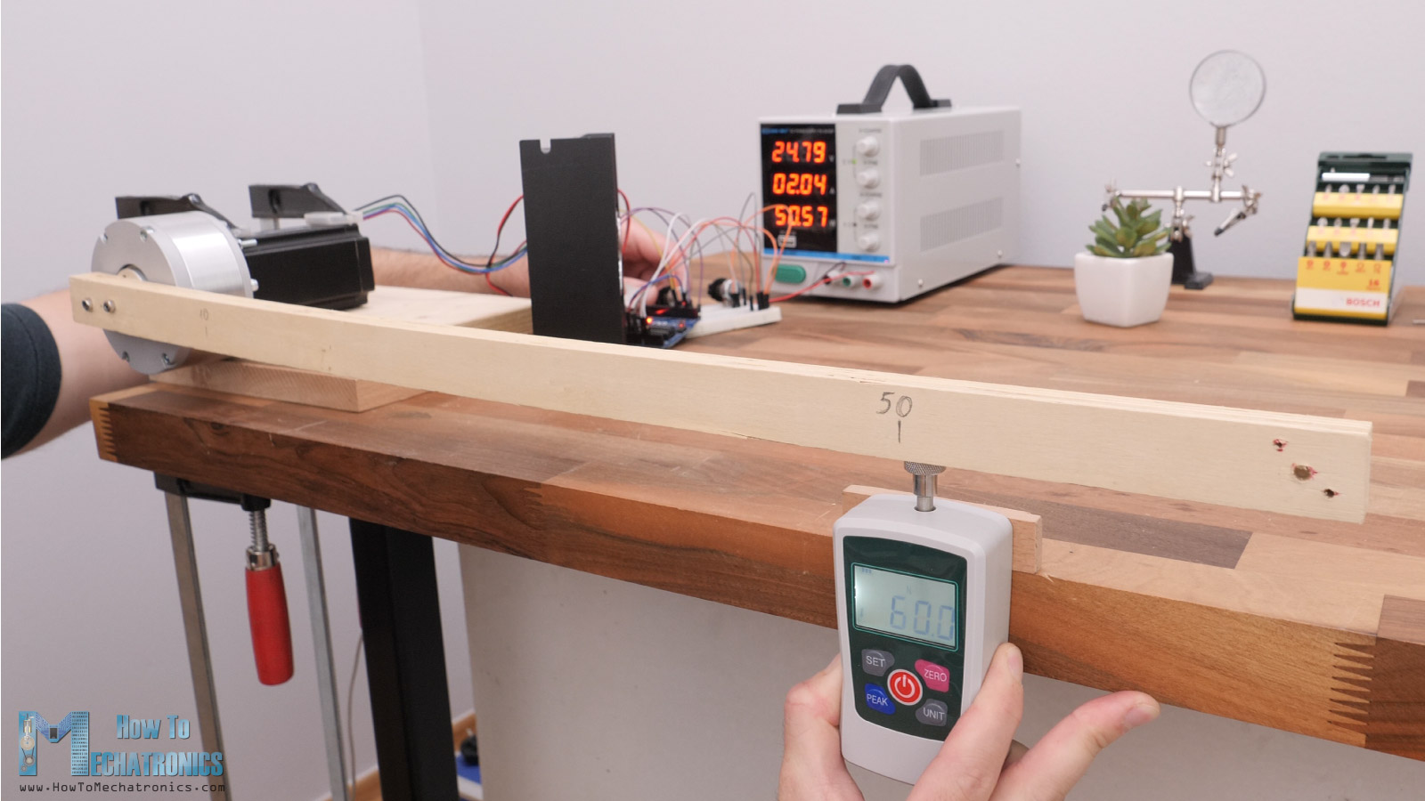
I got a reading of around 60N, which translated into torque is around 3000Ncm or 30Nm of torque. That’s pretty impressive. Just take a look how much the plywood bends under the load.
When measuring the force at a distance of 20cm I got a reading of around 170N, which is around 34Nm of torque. On the other hand, this NEMA23 stepper motor is rated at 2.1Nm, so again, I got a torque increase of around 16 times, just like with the NEMA17 test. Again, that’s efficiency of around 85%.
However, when testing the 3D printed version with the NEMA23 stepper, I got a reading of around 65Nm at a distance of 20cm.
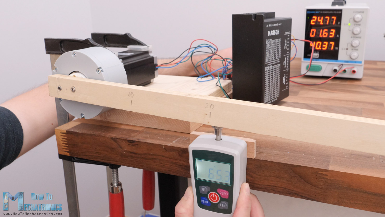
That’s a torque of just around 13Nm, which is actually significantly less compared to the 34Nm torque I got from the CNC machined version. So, with this test we can actually see the difference between the two versions. The 3D printed one just cannot keep up with the forces this powerful NEMA23 stepper can output. Even the threaded insert failed under these loads.
Backlash
Nevertheless, I did some accuracy tests as well. We can see that the repeatability is good, both on the CNC machined and the 3D Printed version. However, once we apply a load, we can notice that drives have some backlash. The CNC machined version had a better result, showing around 4mm play at a distance of around 12cm, when force applied in both directions, whereas the 3D printed version showed a play of 7mm, at a distance of around 15cm.
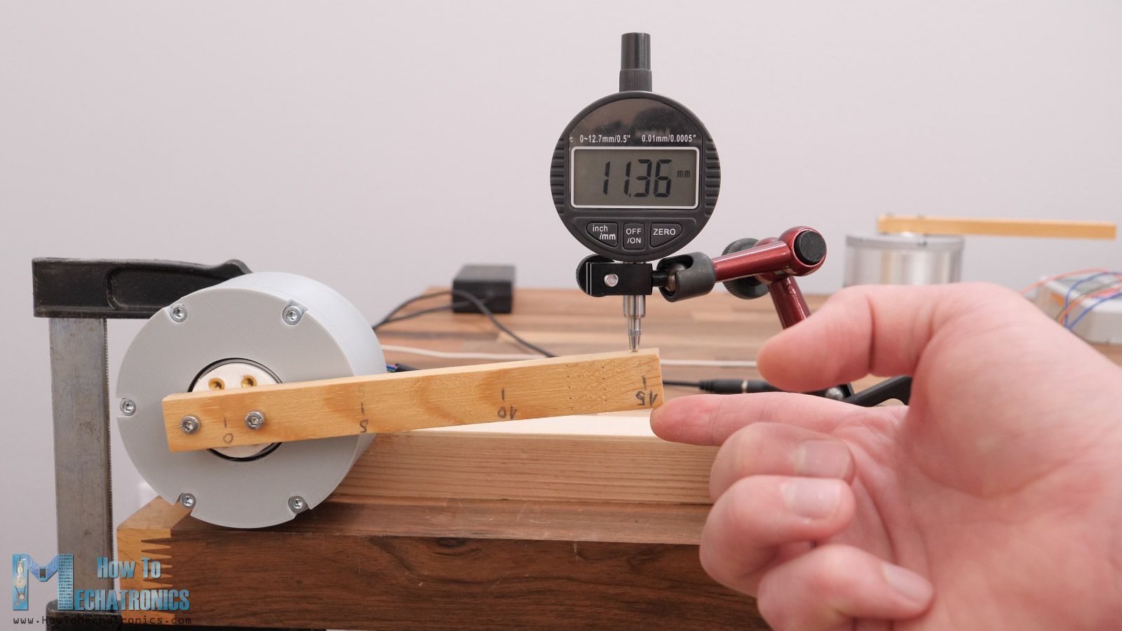
This play of the shaft, or the backlash is present because the bushings dimensions were not that accurate, as well as the fact that I was manually sanding the cycloidal disks profile because I ordered them powder coated by mistake. Because of the same reason, we can also notice how inconsistent this backlash is, some positions on the shaft have more backlash than others.
Conclusion
Nevertheless, we can definitely get better results if we use better bushings and have the cycloidal disk profile machined with the proper dimension and clearance.
Of course, 3D printed version precision can be also improved by printing the cycloidal drive more precisely. We can achieve that by experimenting with the Horizontal expansion feature when 3D printing the parts, and for better durability we can design the disks to be wider and have better contact surface.
I will definitely try to implement this type of cycloidal drive in some of my future videos when making some robotic projects.
I hope you enjoyed this tutorial and learned something new. Feel free to ask any question in the comments section below.