In this tutorial we will learn what is cycloidal drive, how it works, explain how to design our own model and 3D print one so we can see it in real live and better understand how it works.
You can watch the following video or read the written tutorial below.
What is Cycloidal Drive?
A cycloidal drive is a unique type of speed reducer which provides very high reduction ratio with compact but robust design. Compared to conventional gear drives, like spur and planetary, it can achieve much higher reduction rations of up to 10 times in the same space or stage. In addition to that, it features virtually zero-backlash, higher load capacity, rigidity and high efficiency of up 90%. These properties make the cycloidal drives suitable for many applications where positioning accuracy and performance are important such as robotics, machine tools, manufacturing equipment and so on.
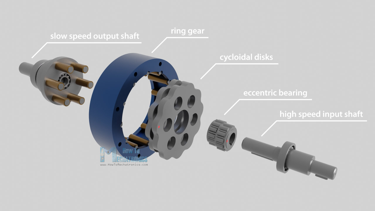
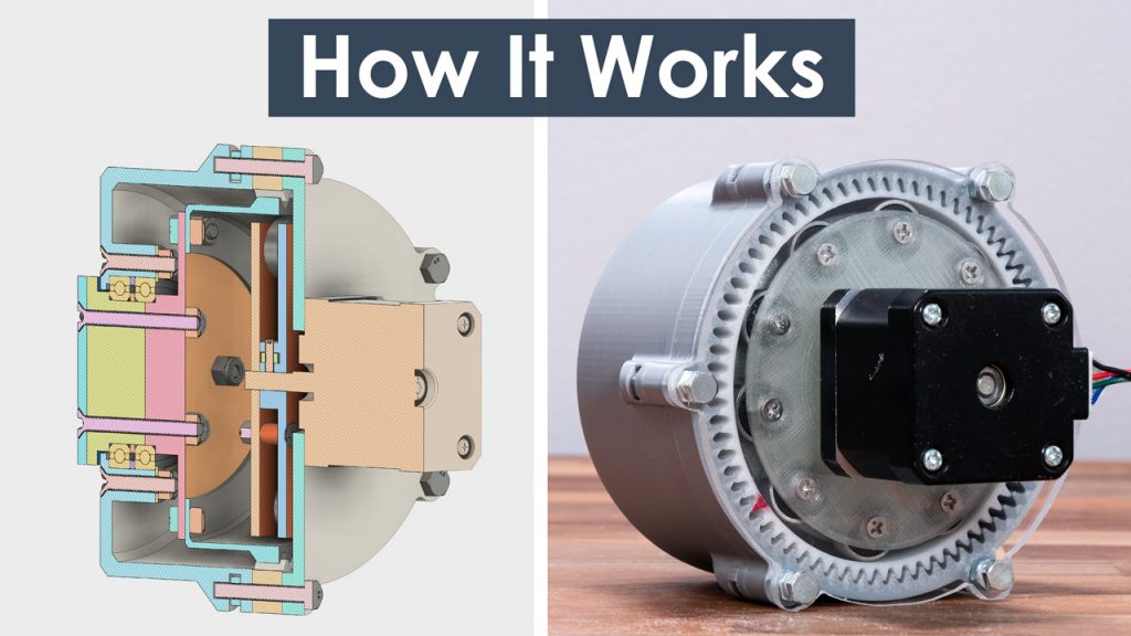
Let’s take a look now what’s inside and how a cycloidal drive works. A cycloidal drive is composed of five main components, a high-speed input shaft, an eccentric bearing or cycloidal cam, two cycloidal disks or cam followers, a ring gear with pins and rollers, and a slow speed output shaft with pins and rollers.
The input shaft drives the eccentric bearing, and the eccentric bearing drives the cycloidal disks around the internal circumference of the ring gear housing. The eccentric motion makes the cycloidal disks teeth or lobes to engage with the rollers of the ring gear housing in a way that they produce reverse rotation at a reduced speed.
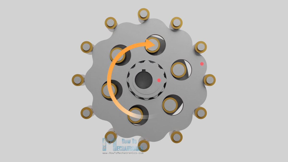
We can take a closer look here and see that the eccentric bearing is actually pushing the cycloidal disk against the ring gear rollers.
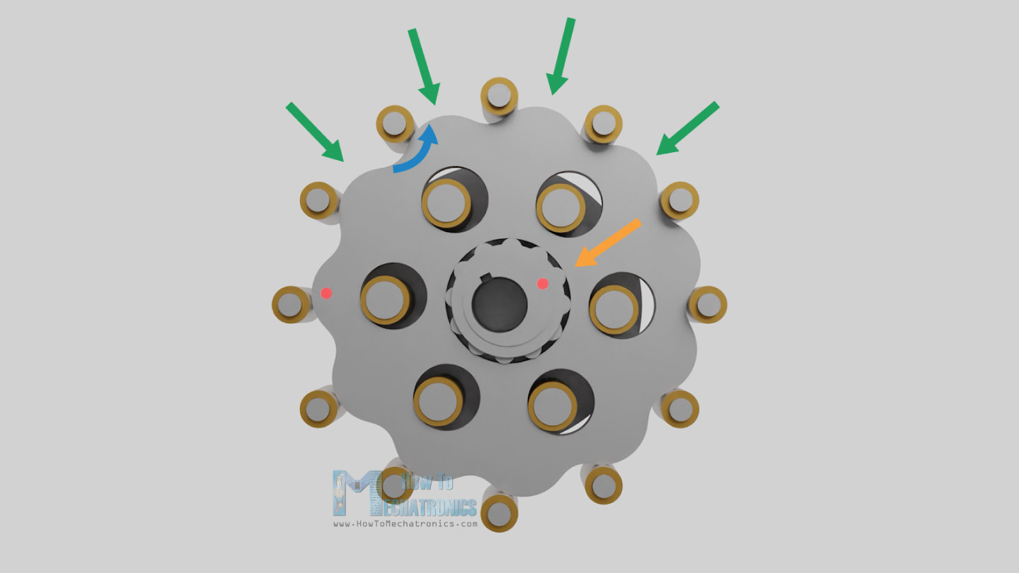
Because of the unique disk shape and its position relative to the ring gear rollers, we can see that as the eccentric bearing progresses, the disk lobes in front of the rotation won’t be able to pass or jump the next ring gear roller, but instead it will slip or roll backward. This behavior is what actually causes the reverse rotation of the disks.
In general, there is one less cycloidal lobe on the disk compared to the number of pins on the ring gear housing. This makes, for one full rotation of the eccentric bearing, the cycloidal disk to move only a distance of one lobe. From this we can see that the reduction ratio depends solely on the number of pins of the ring gear.
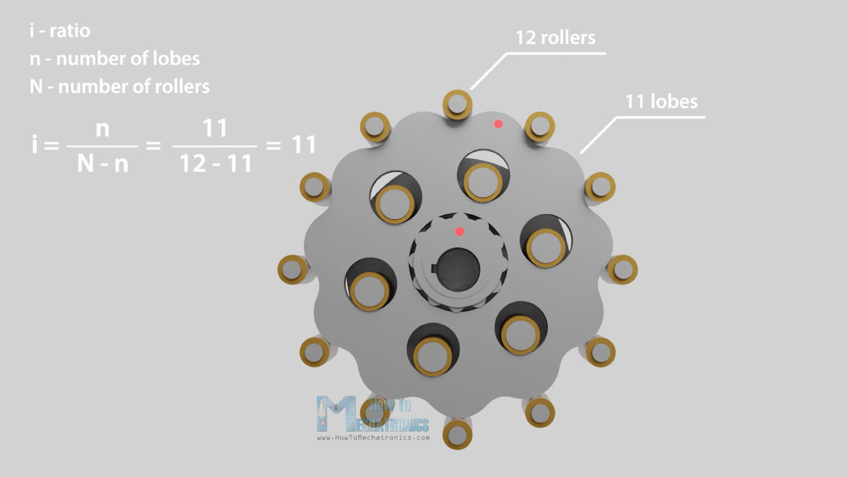
For example, here we have 12 pins on the ring gear, which means 11 lobes on the cycloidal disk, and that’s a ratio of 11:1, or 11 times slower output speed. The size of the disks, the ring gear rollers or the eccentric bearing don’t affect the reduction ration at all.
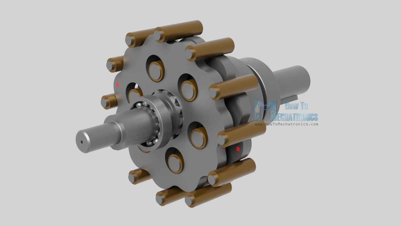
The reduced rotation is transmitted to the output shaft pins through the holes in the cycloidal disks.
There are two cycloidal disks, placed 180 degrees out of phase in order to compensate the unbalance forces caused by the eccentric motion and provide smoother operation at higher speeds.
The name Cycloidal drive comes from the profile of the disk which in turn comes from a cycloid, but more on that in the next section of video where we will design our own cycloidal drive.
How to design a Cycloidal Drive
So, now as we know how a cycloidal drive works, we can move on with designing our own model which we will be able to 3D print it. If we try to 3D print this demo example, it might work, but it would fail quickly as the 3D printing material is not strong enough to withstand the forces and friction that appear in the gearbox.
The critical parts are the rollers that are usually bushings which is great option if the materials are metal, but with a PLA material we will have to use ball bearings instead.
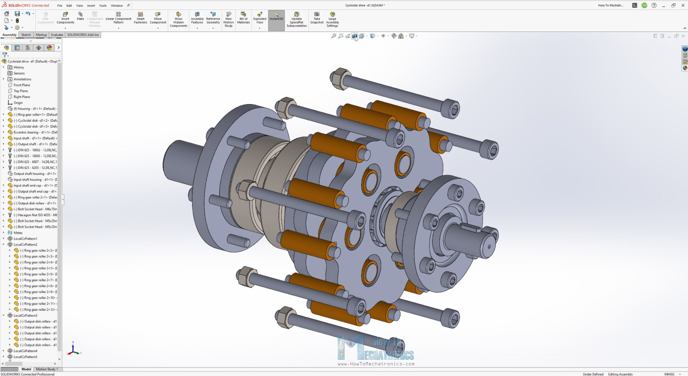
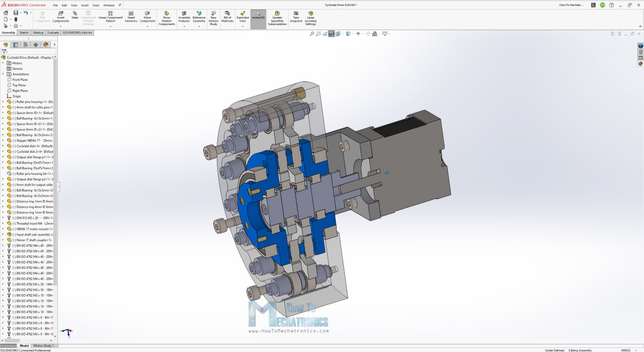
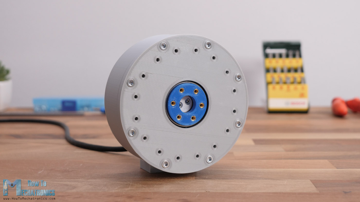
Having that in mind, here’s the cycloidal drive that I designed and uses ball bearings for the rollers.
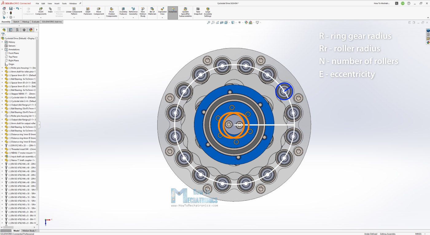
When designing a cycloidal drive there are four main input parameters that define its size and shape of the cycloidal disks, and that’s the ring gear radius, its rollers radius, the number of these rollers, and the eccentricity.
DIY Cycloidal Drive 3D Model
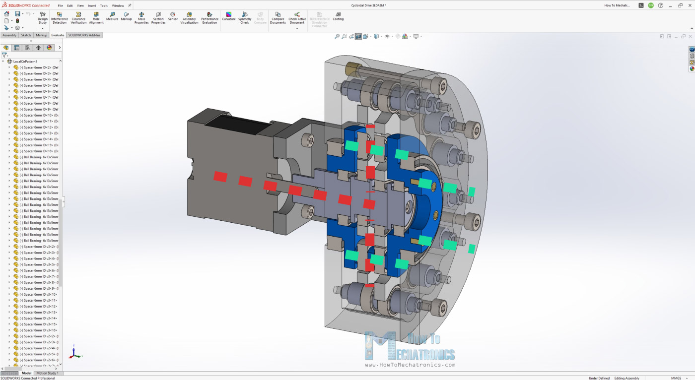
Here’s the cycloidal drive that I designed using SOLIDWORKS and uses ball bearings for the rollers.
At this point let me give a shout-out to SOLIDWORKS for sponsoring this project. Have you heard about 3DEXPERIENCE World; an annual event organized by SOLIDWORKS?
3DEXPERIENCE World 2022 brings a vibrant community of designers, engineers, entrepreneurs and makers together to learn, meet one another, share knowledge together on the newest technologies and best practices.
Be sure to register today at SOLIDWORKS.COM/3DXW22_HOWTOMECH, and attend virtually for free.
Nevertheless, you can find and download this 3D model as a STEP file, as well as explore it in your browser on Thangs:
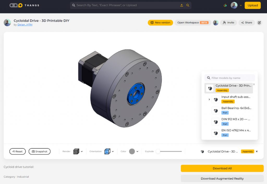
You can download the 3D model .STEP file from Thangs.
Thanks Thangs for supporting this tutorial.
As for the STL files which are used for 3D printing the parts, you can download them here:
Designing
The first thing that I defined was that I wanted a 15:1 reduction ratio for this gearbox, which meant that I needed 16 ring gear rollers. So, I draw a sketch in SOLIDWORKS with 16 rollers around a circle.
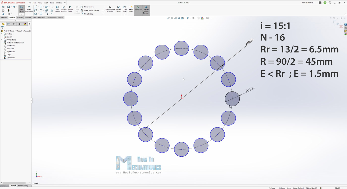
Then I chose to use bearings for the rollers with 13mm outer diameter. Now according to these two parameters I was able to define what size should the ring gear pitch diameter be. I set it to 90mm. The eccentricity value should be smaller than half of the roller diameter, and I chose a value of 1.5mm.
Now that we have the four main input parameters, we can draw the shape or the profile of the cycloidal disk. As I mentioned, the disk profile comes from a Cycloid, which is a curve traced by a point on a circle as it rolls along a straight line without slipping, or its variation, an Epicycloid which is traced when rolling on a circumference of a circle.
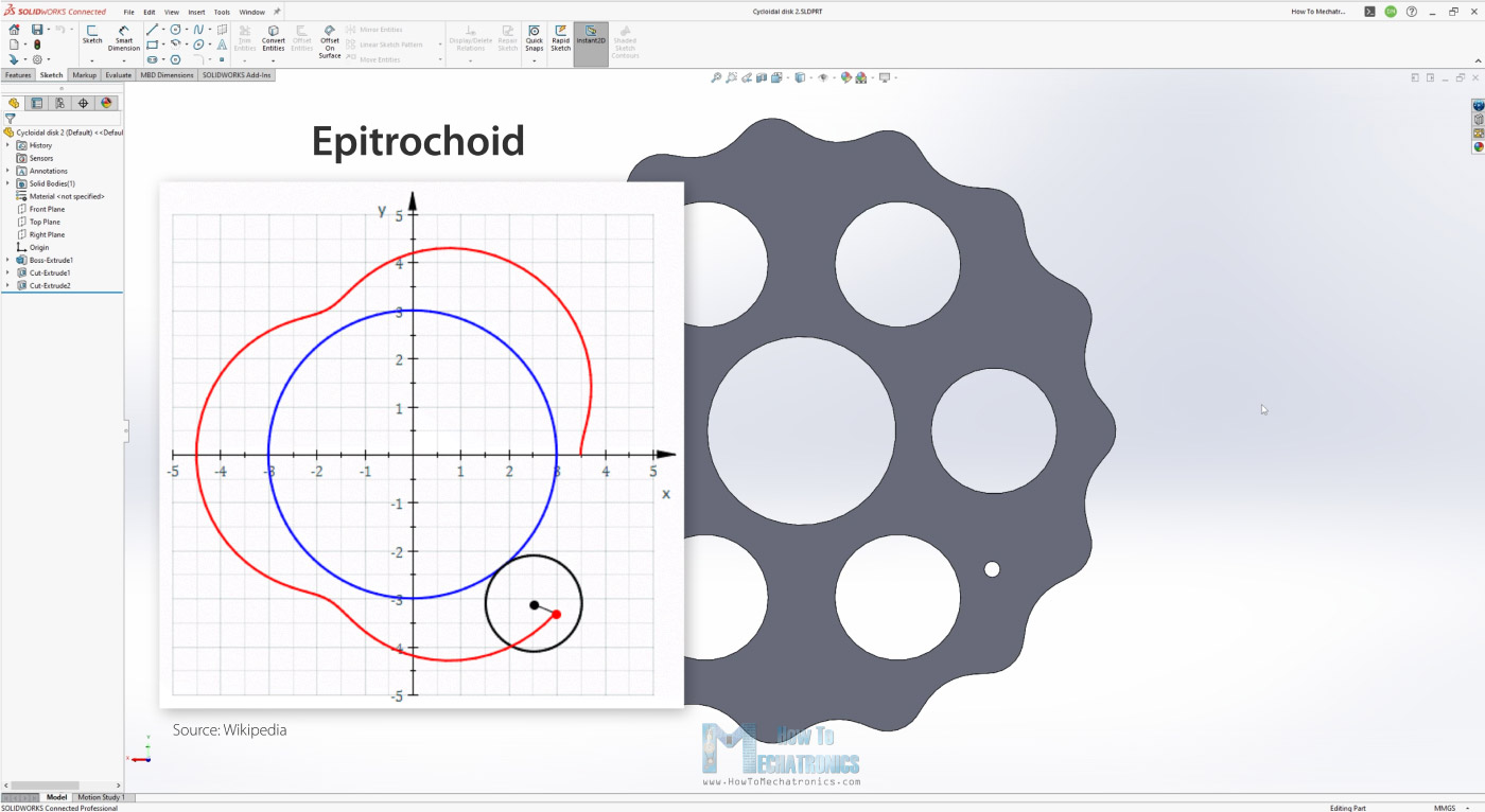
There’s another variation called Epitrochoid, where the tracing point is at a distance from the center of the exterior circle and that’s what the cycloidal disk profile is actually based on.
For drawing such a curve, we can use these parametric equations here but there are also other parameters to include in them, such as the roller’s diameter and the eccentricity. This complicates things a little bit, but luckily there was a great document written by Omar Younis for the SOLIDWORKS Education blog, where he combines all of these parameters in single X and Y parametric equations.
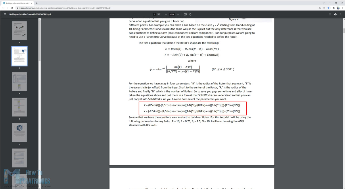
Here’s the equations:
N - Number of rollers
Rr - Radius of the roller
R - Radius of the rollers PCD (Pitch Circle Diamater)
E - Eccentricity - offset from input shaft to a cycloidal disk

x = (R*cos(t))-(Rr*cos(t+arctan(sin((1-N)*t)/((R/(E*N))-cos((1-N)*t)))))-(E*cos(N*t))
y = (-R*sin(t))+(Rr*sin(t+arctan(sin((1-N)*t)/((R/(E*N))-cos((1-N)*t)))))+(E*sin(N*t))

===================


Values for this DIY Cycloidal Drive:

N = 16
Rr = 6.5
R = 45
E = 1.5

x = (45*cos(t))-(6.5*cos(t+arctan(sin((1-16)*t)/((45/(1.5*16))-cos((1-16)*t)))))-(1.5*cos(16*t))
y = (-45*sin(t))+(6.5*sin(t+arctan(sin((1-16)*t)/((45/(1.5*16))-cos((1-16)*t)))))+(1.5*sin(16*t))

Code language: JavaScript (javascript)
Now in order to generate the profile we can simply use the SOLIDWORKS’s Equations Driven Curve tool, insert the two equations appropriately and that will generate the cycloidal disk profile. Of course, for the input parameters we should insert our values.
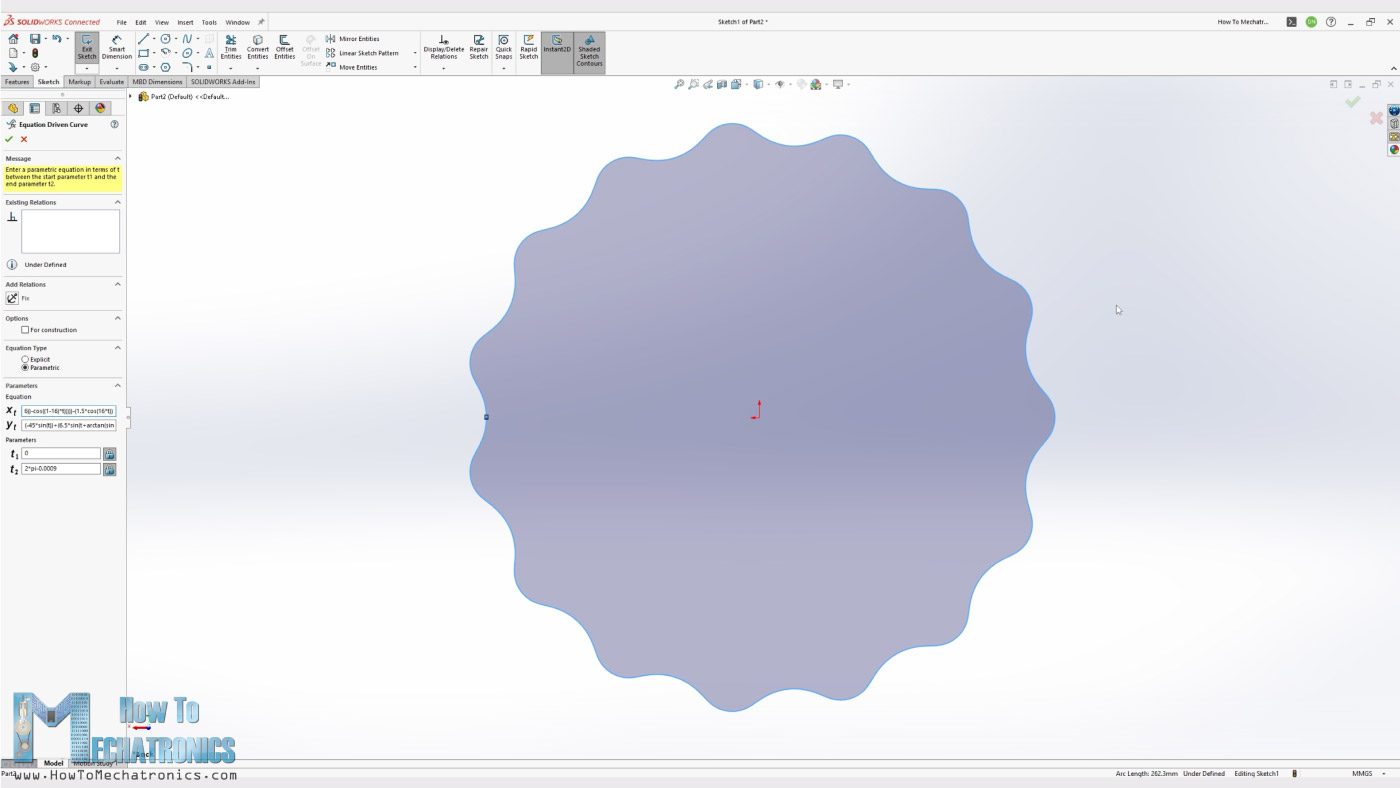
Also note that the curve won’t be generated if the “t” parameters are from 0 to 2*pi or 360 degrees. So, we need to set the t2 parameter a little bit short of 2*pi, and then generate the curve with a small gap which we can connect it using a simple spline.
Now that we have the main parameters of our cycloidal drive defined, the rest just finding a technical solutions for how everything will be connected. Again, considering that we are using not so strong 3D printing material, I designed the shafts of the rollers to be supported on both sides, as well as the input shaft and the output shaft.
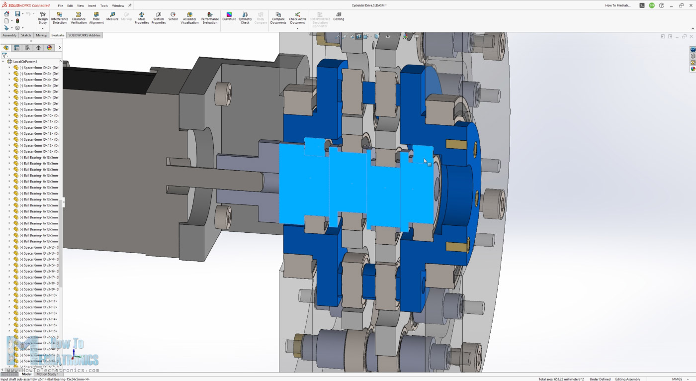
The input shaft is made of several sections and supported with two bearings within the output shaft. The output shaft is also supported with two bearings within the housing.
So, to recap the work of this gearbox, the input from the motor is transmitted to the eccentric input shaft which drivers the cycloidal disks around the gear ring.
The produced reverse motion which is transmitted to the output shaft through the output shaft rollers. And that’s it, now let’s 3D print it and see how it works in real life.
3D Printing
When 3D printing the parts, it’s important to use Hole Horizontal Expansion feature in your slicing software.
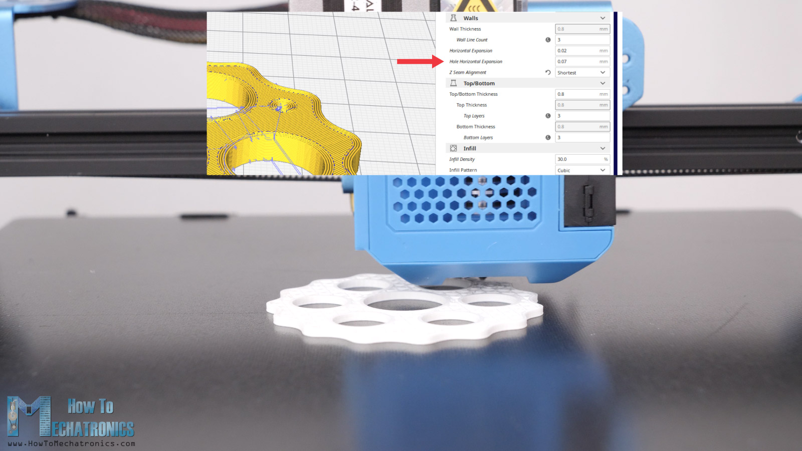
Usually, the holes of 3D printed parts come smaller than the original size, so with this feature we can compose that and get accurate dimension which is very important for this parts. I set mine to 0.07mm, and the Horizontal Expansion can also which compensates for outer dimensions of the parts, to 0.02mm. Of course, you should do some test prints to see what values will give you the best results on your 3D printer.
Assembling the Cycloidal Gearbox
So, here are all of the 3D printed parts, as well as the bearings and the bolts needed for assembling the cycloidal drive.
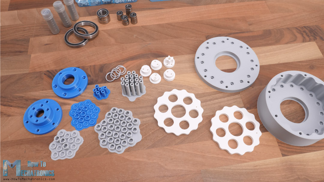
Here’s a list of all components needed for assembling this cycloidal drive:
- Ball bearing 6x13x5mm 686-2RS – x44 …….. Amazon / AliExpress
- Ball bearing 15x24x5 6802-2RS – x4 ………….. Amazon / AliExpress
- Ball bearing 35x47x7 6807-2RS – x2 ………….. Amazon / AliExpress
- 6x35mm steel rod ……………………………………….. Amazon / AliExpress
- Threaded inserts …………………………………………. Amazon / AliExpress
- M3 and M4 bolts from your local hardware store – I will include a complete list of bolts needed for this project in few days
Disclosure: These are affiliate links. As an Amazon Associate I earn from qualifying purchases.
I started with inserting the ring gear pins to housing. These pins accommodate the ring gear rollers or bearings but they are just 6mm in diameter. I wasn’t sure whether they were strong enough not to break under the load of the cycloidal disk.
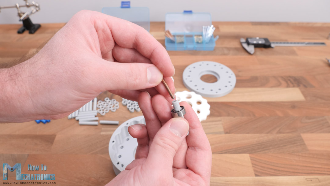
Therefore, I made them hollow, and inserted into them 3mm metal shafts which I had laying around. This way the pins will be strong enough for sure. Of course, there are smarter solutions for this. For example, we could use M6 bolts instead, but what I don’t like about it is that the M6 bolts are slightly smaller than 6mm, so the bearing would wobble. Ideal, here we could use a proper 6mm rods, which are actually easily available to buy even with this particular size of 35mm.
Once we place all pins in place, we can insert the bearings in this order, a 7mm distance ring, a bearing, then 3mm distance ring, a bearing and another 7mm distance ring.
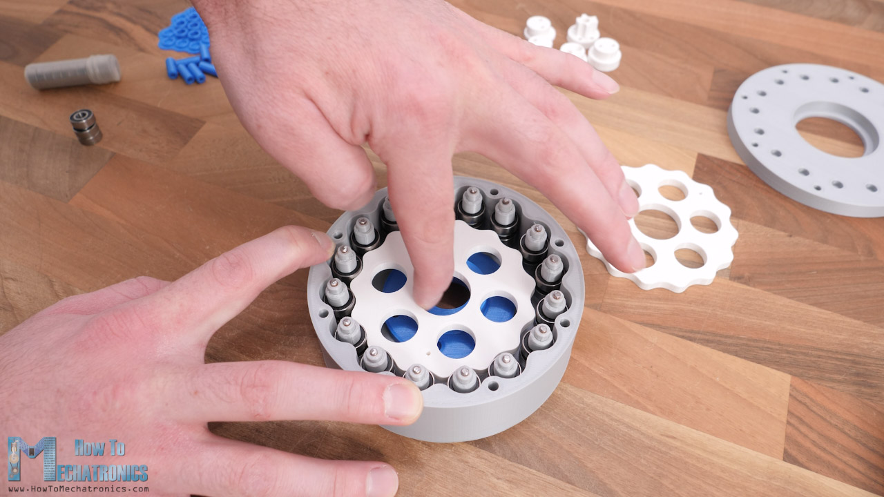
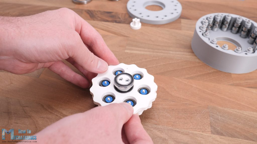
The cycloidal drive should now fit in this ring gear that we created, and if we try to move rotate the disk with an eccentric motion, by pushing to the sides while rotating, the disk should start rotating reversely.
Next, we can assemble the input shaft which is made of four sections. In each section we need to place a bearing and some distance rings, and because of the eccentricity we won’t be able to do that unless the shaft is made in sections.
For connecting the sections together I’m using two M3 bolts which go through all of them. We can note here that the holes for these M3 bolts are made slightly smaller than the M3 bolts so that the bolt will make a thread in them and have tighter fit.
Here’s how the shaft should look like when assembled, but I actually had to insert the cycloidal disks as well as now I couldn’t do it. So, I disassembled it and assembled it again with the disk inserted as well.
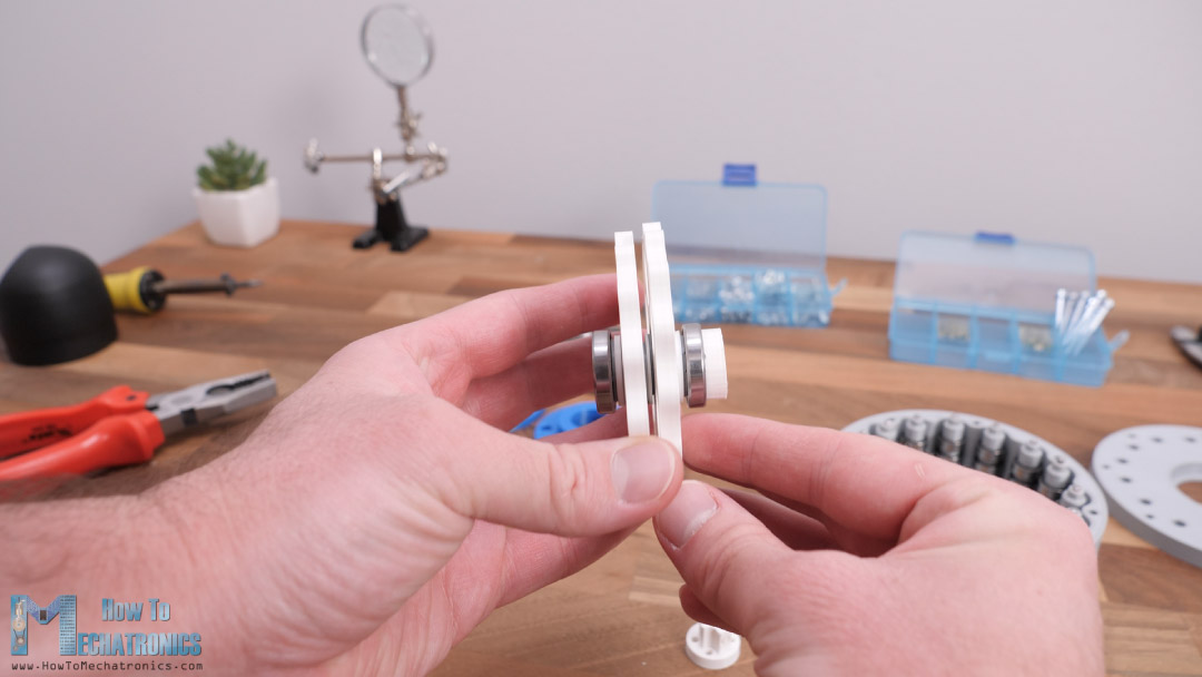
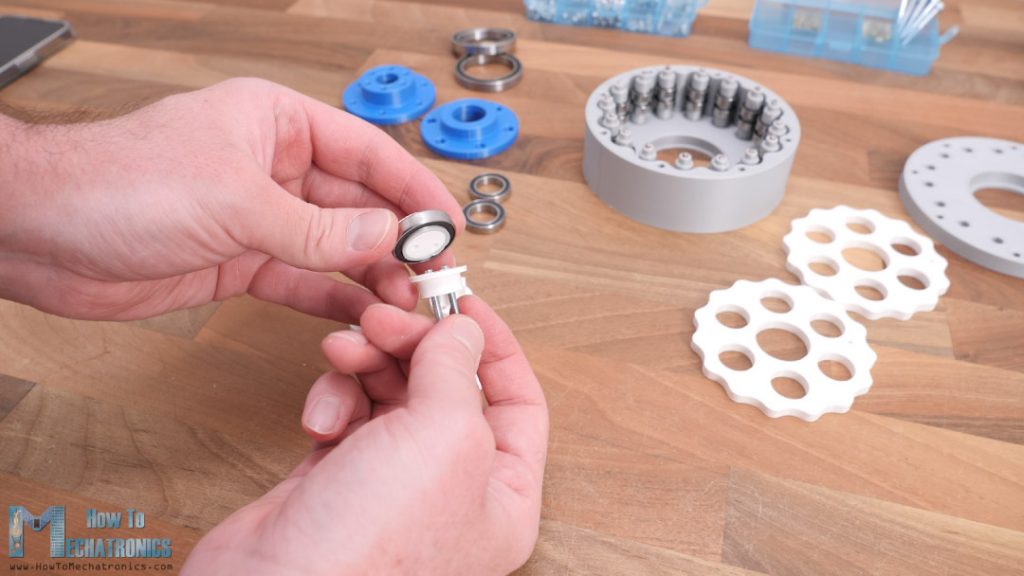
I continued with assembling the output shaft. Here we need to install the output rollers or bearings, and we do that in similar way as shown for the ring gear rollers. A 6mm pin, with 13mm bearings and some distance rings inserted through some 20mm long M3 bolts.

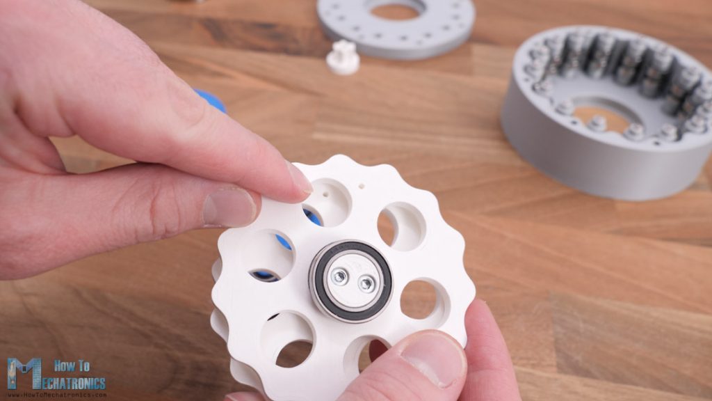
When inserting these output rollers through the openings of the cycloidal disk, it’s important to position the two disks relative to each other 180 degrees out of phase. To help with this I made small holes on both disks 180 degrees out of phase, so here we just have to match them and we are good to insert the rollers through.
Please note that this is a bit tight fit, but if the hole dimensions are accurate, we will be able to make the fit.
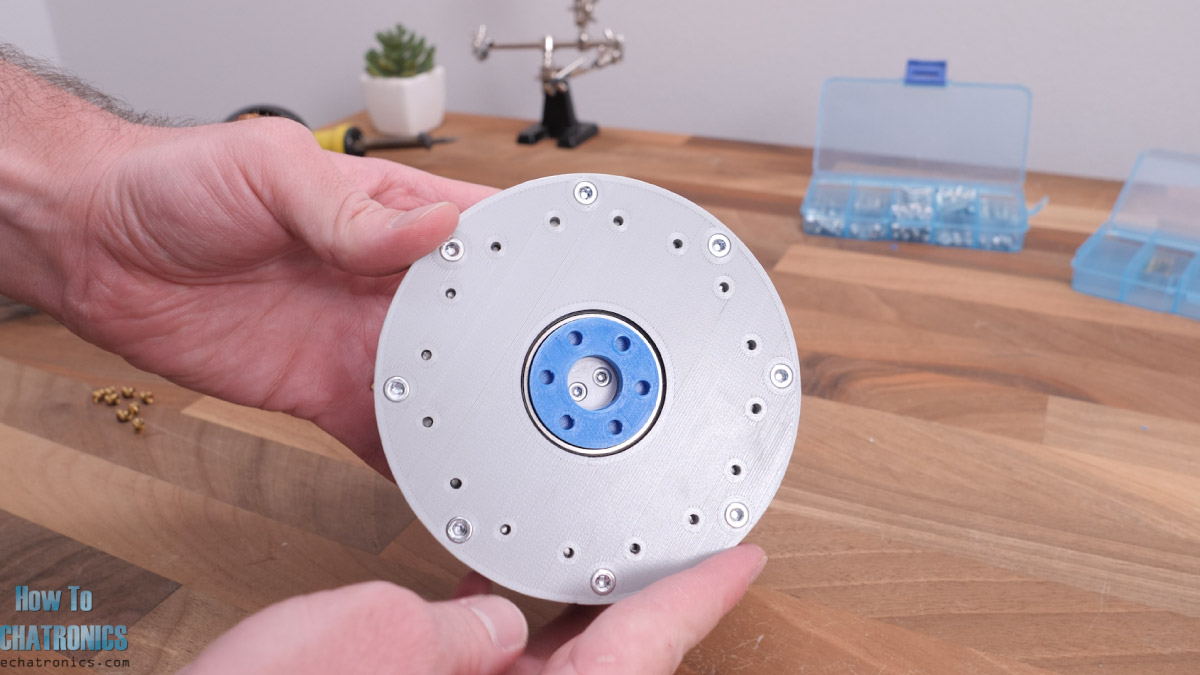
Now we can secure these pins to the other flange on the other side, but for that purpose first we need to install some threaded inserts into the flange. I’m using these threaded inserts in order the whole assembly to be more compact.
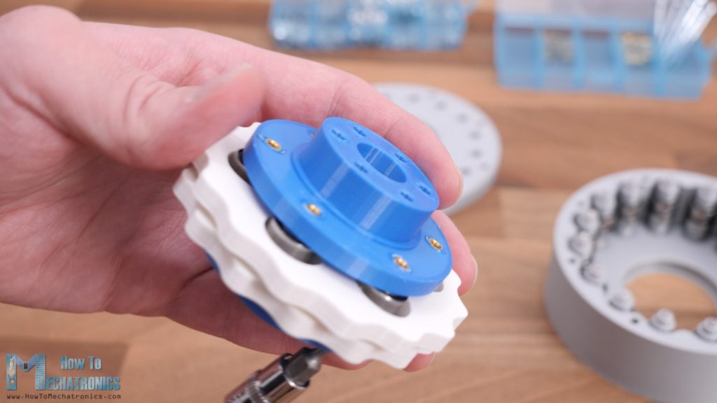
So, once the input and the output shaft are assembled together, we can install this whole assembly into the housing through a bearing with 47mm outer diameter.
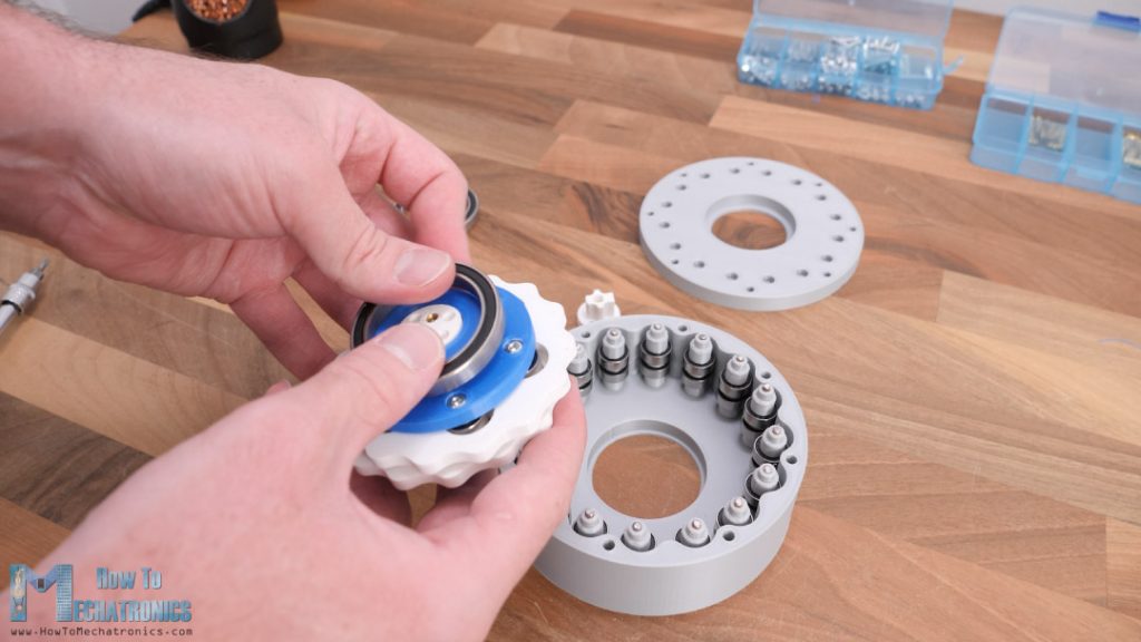
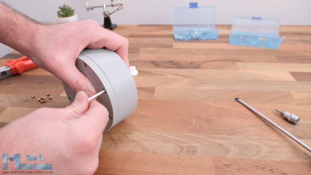
Then we can install one more bearing like this in the front of the shaft, and insert housing lid in place. This is also a tight fit as all 16 pins should fit in their housing lid slots, so we have to use a bit of force to insert it.
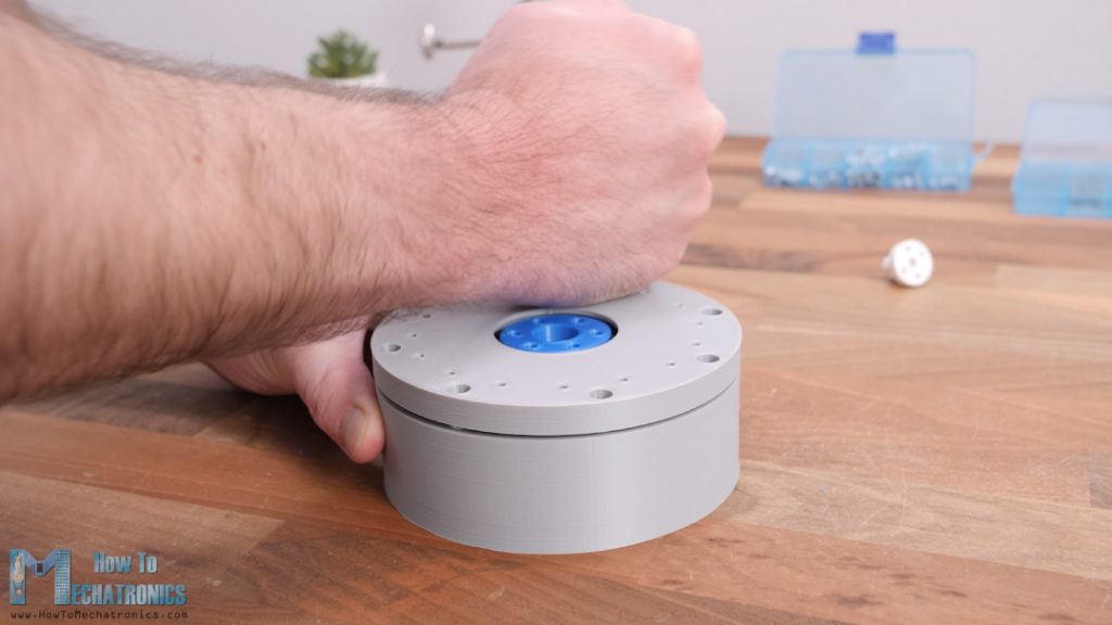
On the back side of the housing, I installed some M4 threaded inserts, and then secured the lid and t he housing together with some 40mm M4 bolts.
And that’s it! If it’s fair to say, just take a look at this beauty. I really like how this cycloidal gearbox turned out, clean design with nothing popping out of it.
Testing the Cycloidal Drive
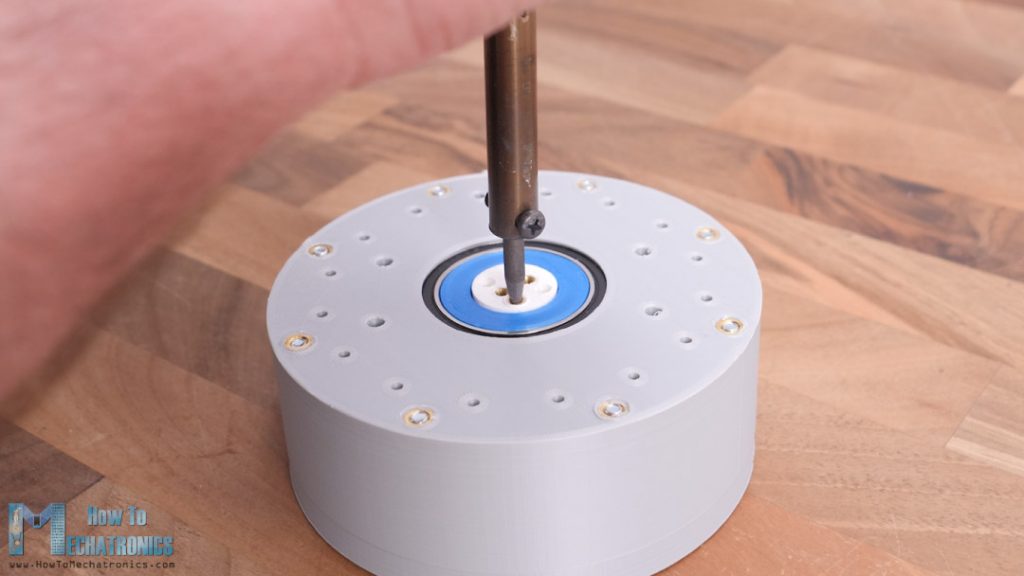
Nevertheless, now let’s attach a motor to it and see how it will work. At the back side of the input shaft, I installed few more threaded inserts so that we can easily attach various shaft couplers.
For testing the gearbox, I will use a NEMA 17 stepper motor so I attached a suitable 3D printed shaft coupler to the input shaft. I secured the stepper to a 3D printed mounting bracket and inserted the motor shaft into the coupler and secured the mounting bracket to the housing.
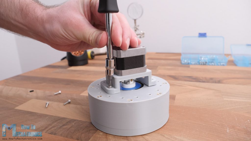
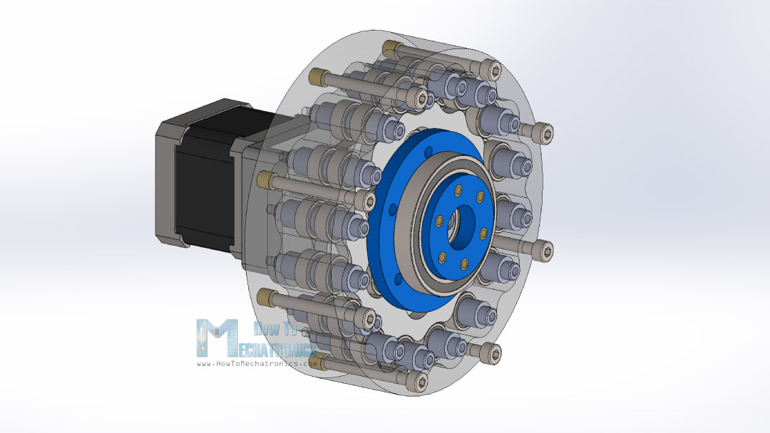
One last thing is to install some threaded inserts at the front of the output shaft so we can attach things to it. Here’s the final appearance of this cycloidal drive, in combination with a NEMA 17 stepper motor, but of course we can use any other type of motor here.
And there we have it. To be honest, I was really surprised how smooth the output of this gearbox turned out. From the front we can see both the input and the output shaft rotating at the same time, in the opposite direction and with speed difference of 15:1.
I was also able to run the gearbox without the front lid, and so we can see everything explained previously in action.
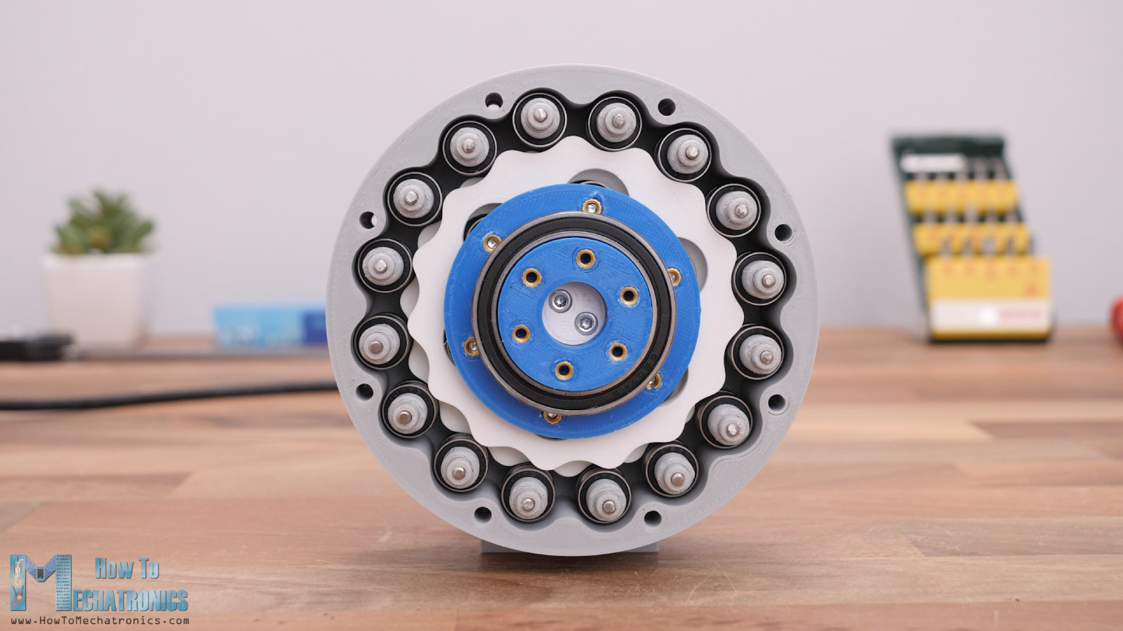
The motion is simply mesmerizing.
At the end, I made some tests to check the gearbox performance. One more thing to note here is that this cycloidal drive is also back-drivable which can be good feature to have for some applications.
So, here I’m measuring the force this gearbox can produce at a distance of 10cm. I got a reading of around 26N, which translated to torque, is about 260 Ncm, and this NEMA 17 stepper which is just 34mm long is rated at 26 Ncm.
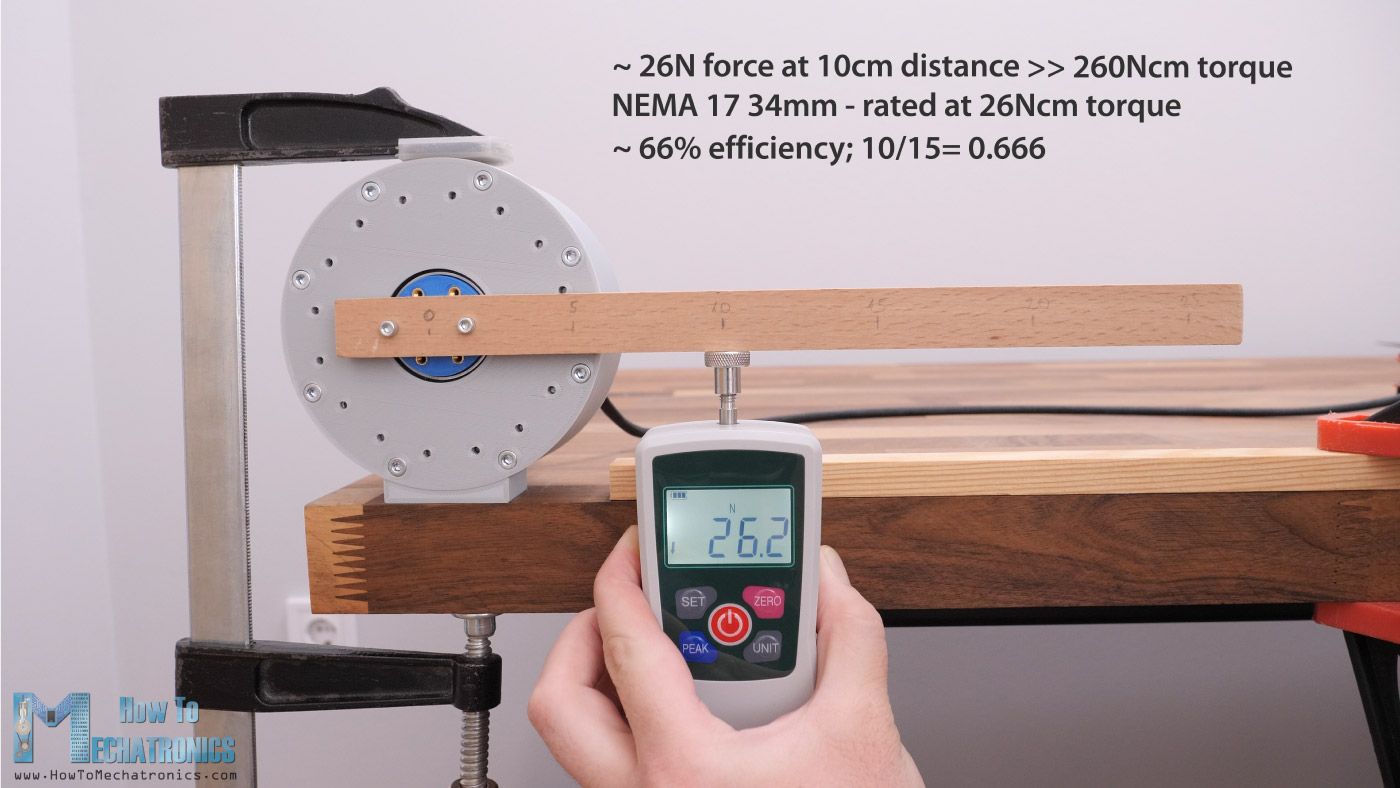
That means that we’ve got torque increase of around 10 times with the cycloidal drive. That’s efficiency of around 66%, considering that the reduction ratio is 15:1 and in ideal conditions we should have got 15 times torque increase. Nevertheless, that’s still a great result considering that everything is 3D printed with a budget 3D printer and the parts are not that accuracy as we would get with some pro printers or CNC machines in case of all metal gearbox.
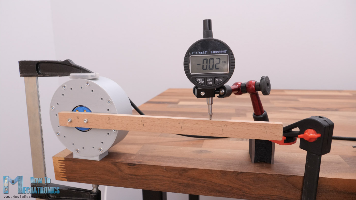
I also made some accuracy tests, which also showed good results.
I would definitely use this type of gearbox in future videos when making some robotic projects.
I hope you enjoyed this video and learned something new. If you have any questions, feel free to ask them in the comments section below.
Excellent project.
We will build these to control our Robotic Agricultural Spray Vehicle and the steering control on our Robotic Echo Sounder Vehicle.
As the loads are under 30 kilograms these should be the answer. I have tried various.gear boxes and proving too bulky to achieve the ratios/torque.
Thank you if successful we will contribute to your site for compensation of your work.
Hello,
Thanks for this informative article and video.
Good days,
Hey,
Cool article and video. It seems to me as if the principle on this gear and the Strain Wave Gear (covered by you before) is almost the same? The input shaft is excentred and interacts with a outer fixed cogweel. The Strain Wave Gear profits from higher reduction rates due to smaller cogs (comparing to the bearings as cogs).
Still an awesome gear!
Thank you for your content
Hey, thanks for the input!
Yeah, their principle of work is rather similar and both have their own pros and cons.
Cheers!