In this tutorial we will learn what is Strain Wave Gear, also known as Harmonic Drive. First, we will explain its working principle, then design our own model and 3D print it so we can see it in real life and better understand how it works.
You can watch the following video or read the written tutorial below.
What is Strain Wave Gear?
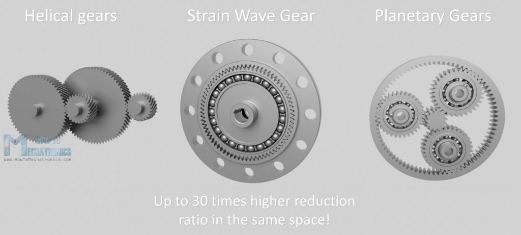
A Strain Wave Gear is a unique type of mechanical gearing system which allows very high reduction ratio in a compact and lightweight package. Compared to traditional gearing systems such as helical gears or planetary gears, it can achieve much higher reduction ratios of up to 30 times in the same space. In addition to that, it has zero-backlash characteristic, high torque, accuracy and reliability. Therefore, this gearing system is used in many applications, including robotics, aerospace, medical machines, milling machines, manufacturing equipment and so on.
The Strain Wave Gear was invented in 1957 by C. Walton Musser, and the other name which is commonly used for it, “Harmonic Drive”, is actually a brand name of strain wave gear trademarked by the Harmonic Drive company.
How It Works
All right, so let’s take a look how it works now. A harmonic drive has three key components, a wave generator, a flex spline and a circular spline.
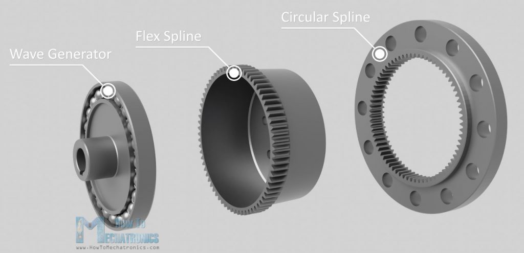
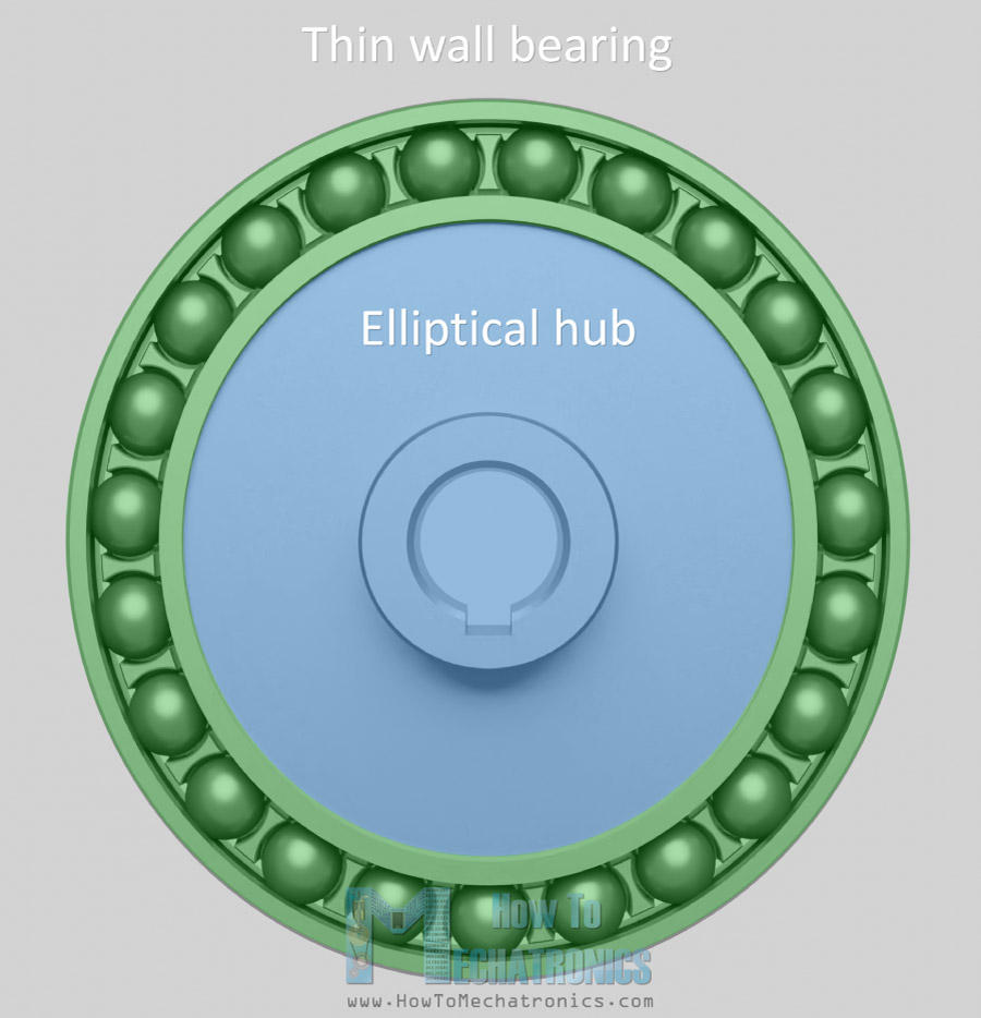
The wave generator has an elliptical shape and consists of an elliptical hub and a special thin walled bearing which follows the elliptical shape of the hub. This is the input of the gear set and it’s connected to the motor shaft.
As the wave generator rotates it generates a wave motion.
The Flex spline has a form of a cylindrical cup and it’s made out of flexible but torsionally stiff alloy steel material. The sides of the cup are very thin but the bottom is thick and rigid.
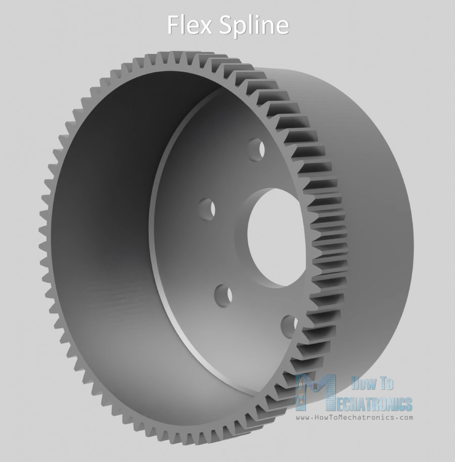
This allows the open end of the cup to be flexible, but the closed end to be quite rigid and therefore we can use it as an output and connect the output flange to it. The flex spline has external teeth on the open end of the cup.
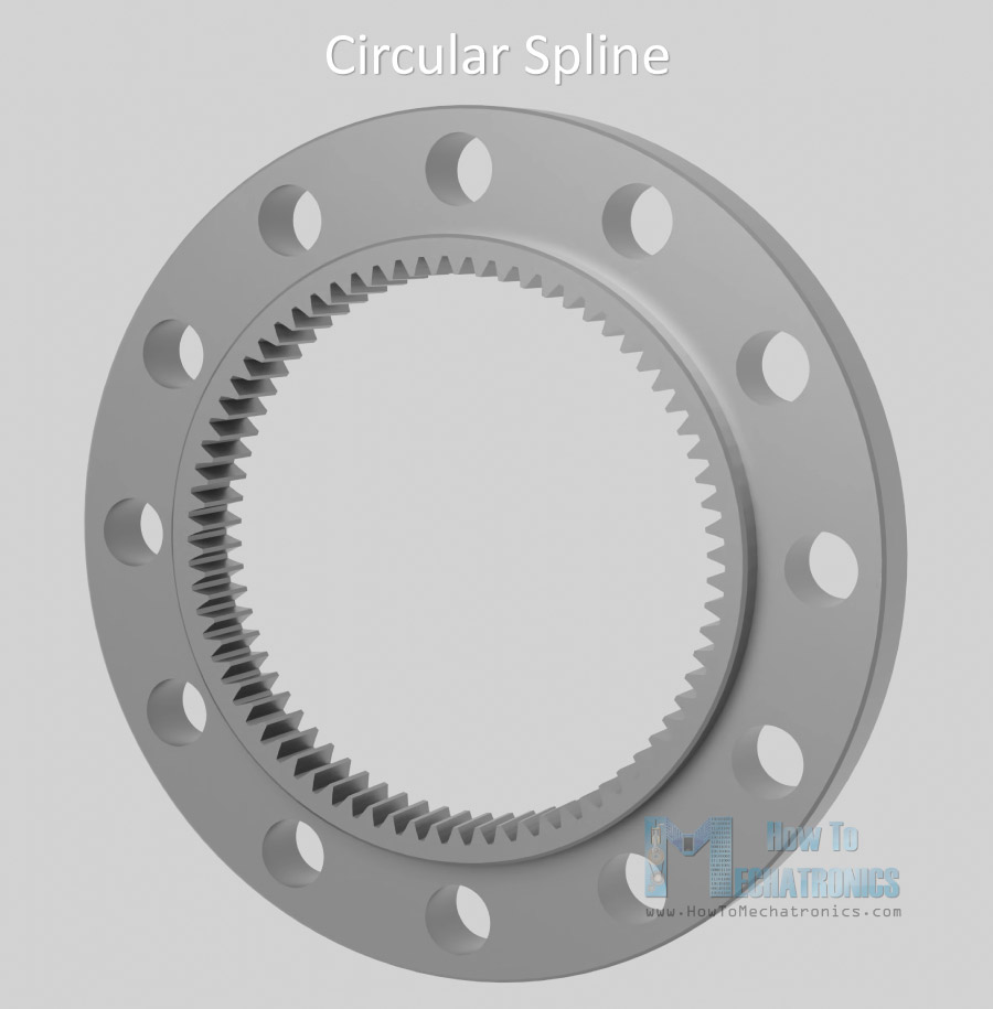
On the other hand, the Circular spline is a rigid ring with teeth on the inside. The circular spline has two more teeth that the flex spline, which is actually the key design of the strain wave gear system.
So, when we insert the wave generator into the Flex spline, the flex spline takes the shape of the wave generator.
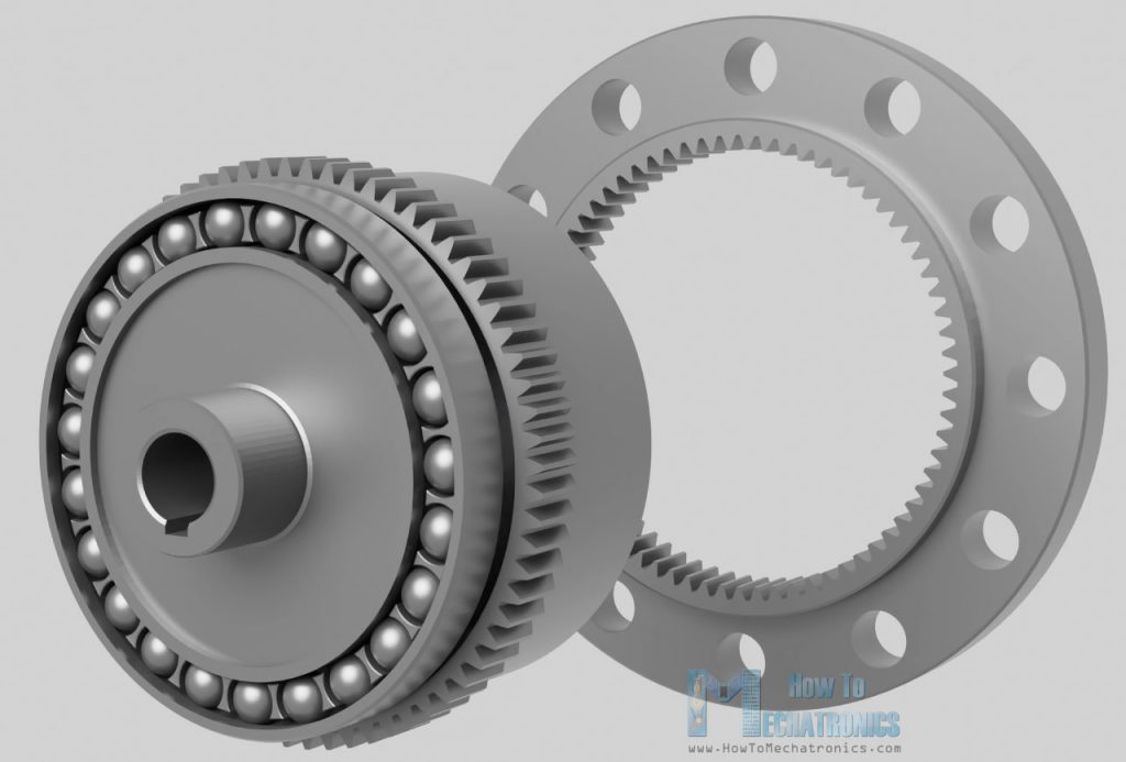
As the wave generator rotates, it radially deforms the open end of the flex spline. The wave generator and the flex spline are then placed inside the circular spline, meshing the teeth together.
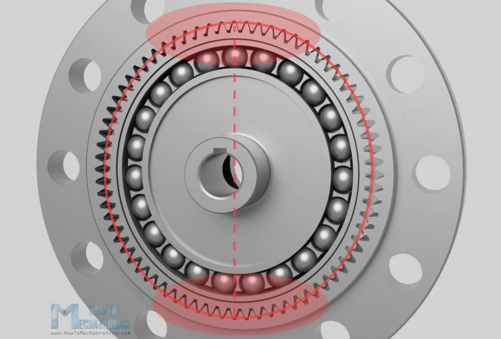
Because of the elliptical shape of the flex spline, the teeth mesh only in two regions on the opposite sides of the flex spline, and that’s across the major axis of the Wave Generator ellipse.
Now, as the wave generator rotates, the Flex spline teeth that are meshed with those of the circular spline will slowly change position. Because of the tooth count difference between the Flex spline and the Circular spline, for each 180 degrees rotation of the wave generator, the teeth meshing will cause the flex spline will rotate a small amount backward relative to the wave generator. In other words, with each 180 degrees rotation of the wave generator, the flex spline teeth mesh with the circular spline will advance by only one tooth.
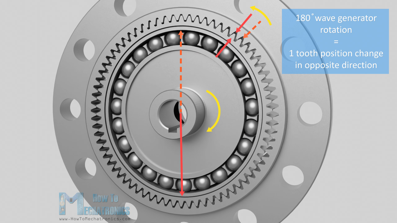
So, for a full rotation of 360 degrees of the wave generator, the flex spline will change position or advance by two teeth.

For example, if the flex spline has 200 teeth, the wave generator has to do 100 revolutions in order the flex spline to advance 200 teeth, or that’s just a single rotation for the flex spline. That’s a ratio of 100:1. In such a case the circular spline will have 202 teeth, as the circular spline number of teeth is always greater that the flex spline teeth by two.
We can easily calculate the reduction ratio with the following formula. The ratio is equal to the flex spline teeth – circular spline teeth, divided by the flex spline teeth.
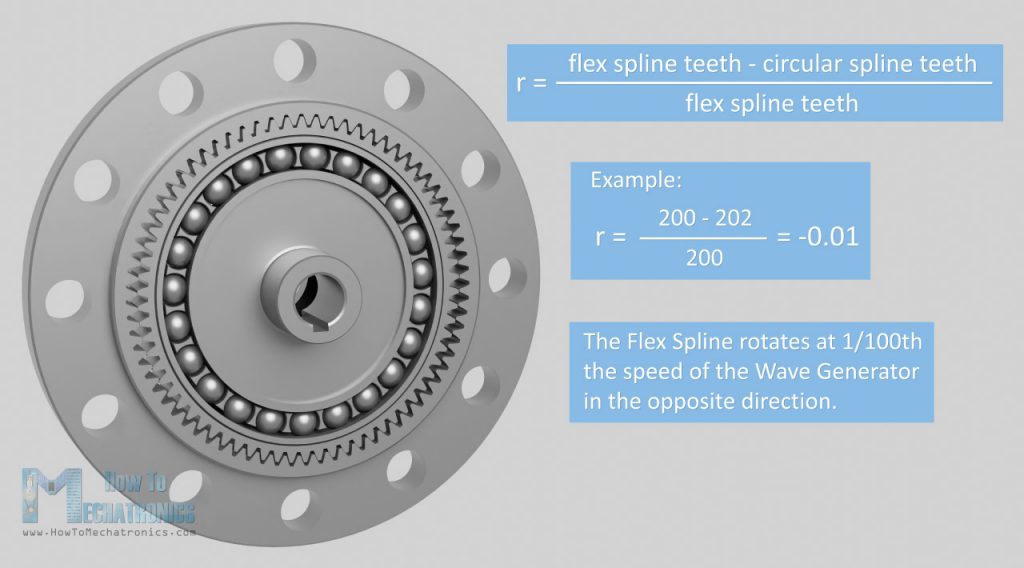
So, with the example of 200 teeth on the flex spline and 202 teeth on the circular spline, the reduction ratio is -0.01. That’s 1/100 the speed of the wave generator and the minus sigh indicates that the output is in the opposite direction.
We can get different reduction ratios by changing the number or teeth.
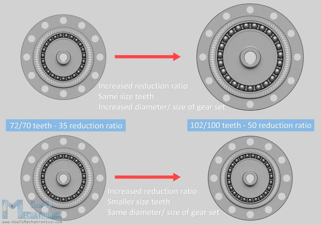
We can achieve that by either changing the mechanism diameter while having the same size teeth, or by changing the teeth size preserving the size and weight of the gear set.
Strain Wave Gear – Harmonic Drive 3D Model
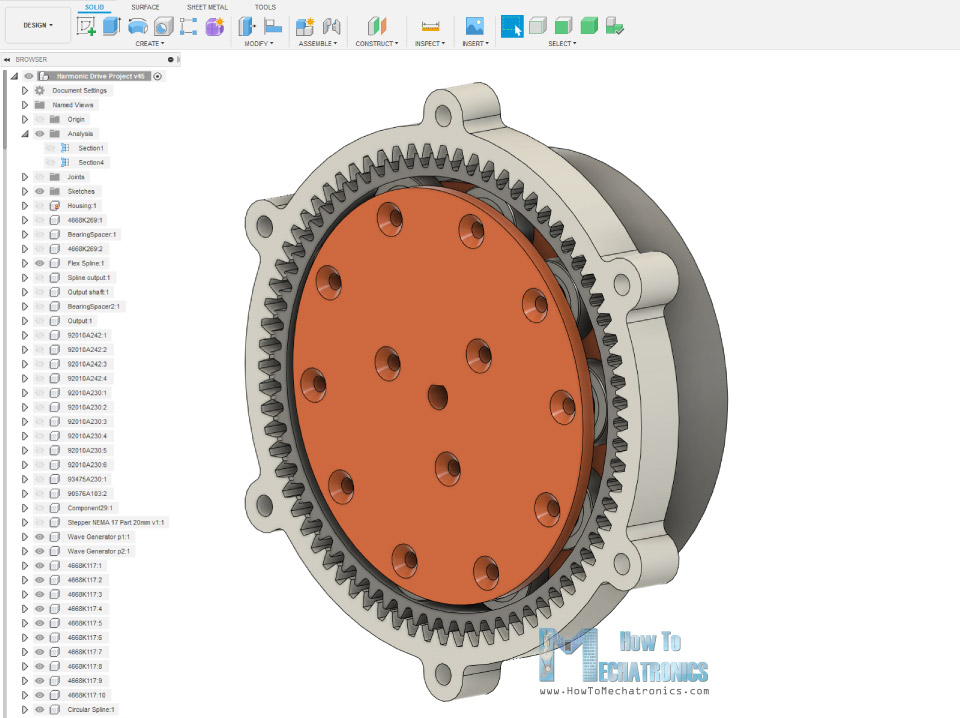
Ok, so now as we know the theory behind the Strain Wave Gear, let me show you how I designed one so we can build it with just using a 3D printer.
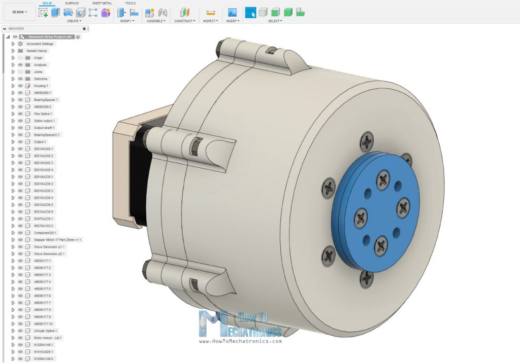
I designed this model of Strain Wave Gear using Fusion 360. All of these parts can be 3D printed, so we just need some bolts and nuts and some bearings to complete the assembly. As for input I chose to use a NEMA 17 stepper motor.
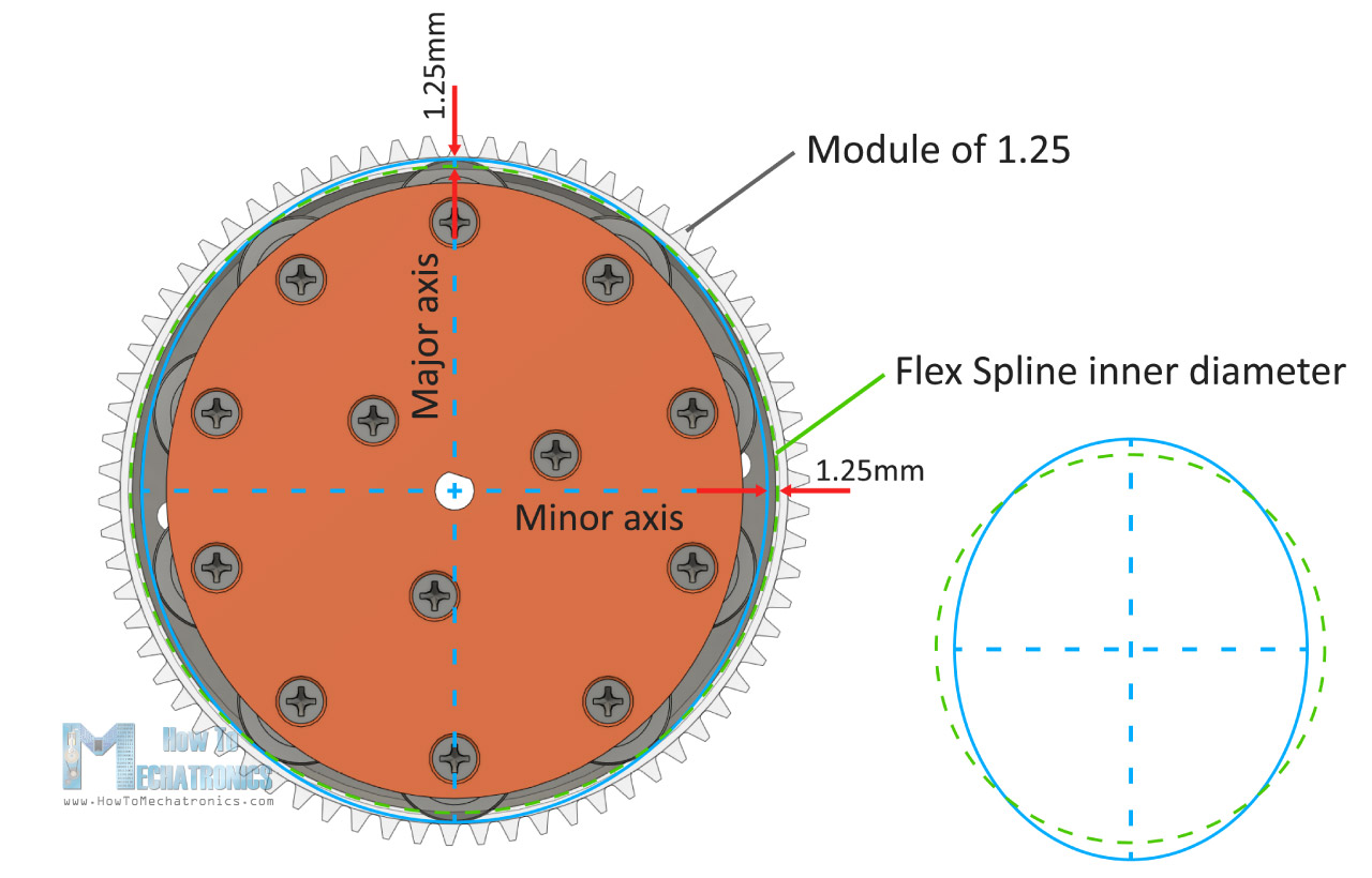
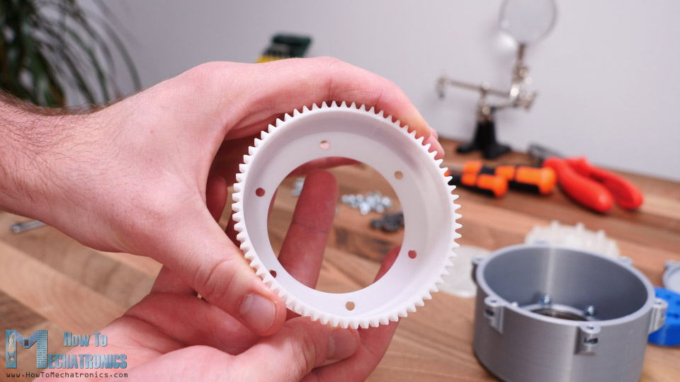
Here’s how I designed the 3 key elements of the Strain Wave Gear, the circular spline, the flex spline and the wave generator. As 3D printers have their own limitations how good, accurate and precise can print, the first that I had to decide was the module of the gears or how big or small the teeth will be. I chose a module of 1.25 and 72 teeth for the circular spline.
Of the course, the flex spline needs to have 2 teeth less, or that’s 70 teeth. That will result in 35:1 ratio while having a relatively small size of the gear set.
As for the wave generator, we cannot really use those special type of thin wall bearings mentioned earlier, as they are not easy to find. Instead, we will use normal ball bearings arranged around a circumference of an ellipse. The dimensions of the ellipse should be made according to the dimensions of the inner wall of the flex spline.
I made the major axis radius of the ellipse to be 1.25mm bigger that the radius of the inner wall of the flex spline. On the other hand, the minor axis radius of the ellipse is 1.25mm smaller.
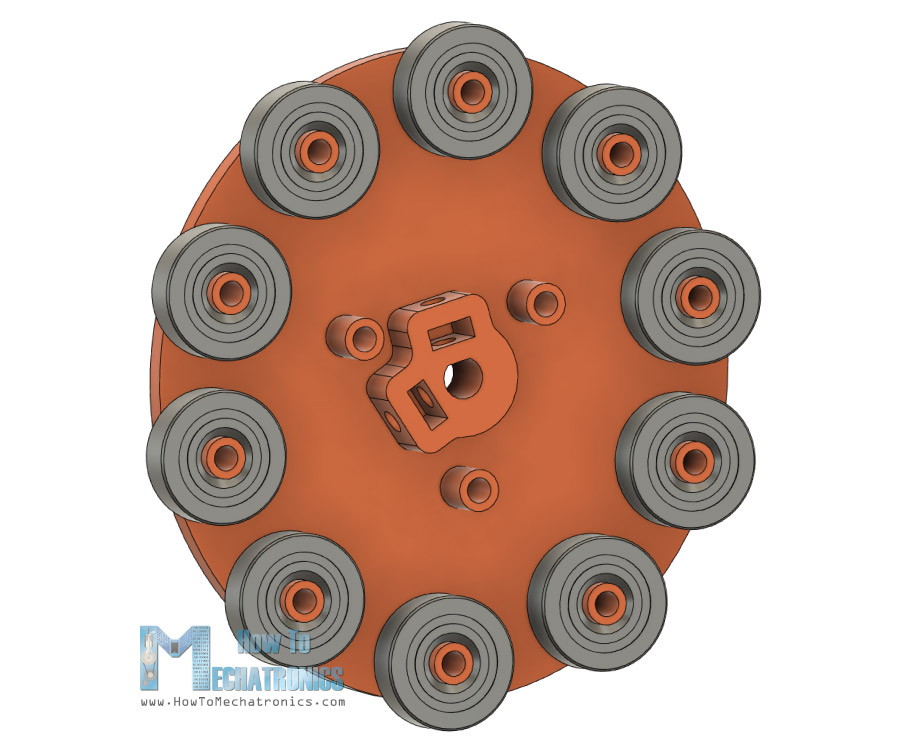
The wave generator will be made out of two sections on which the 10 bearings can be easily attached. One of these sections also features a shaft coupler suitable for securing the NEMA 17 stepper motor.
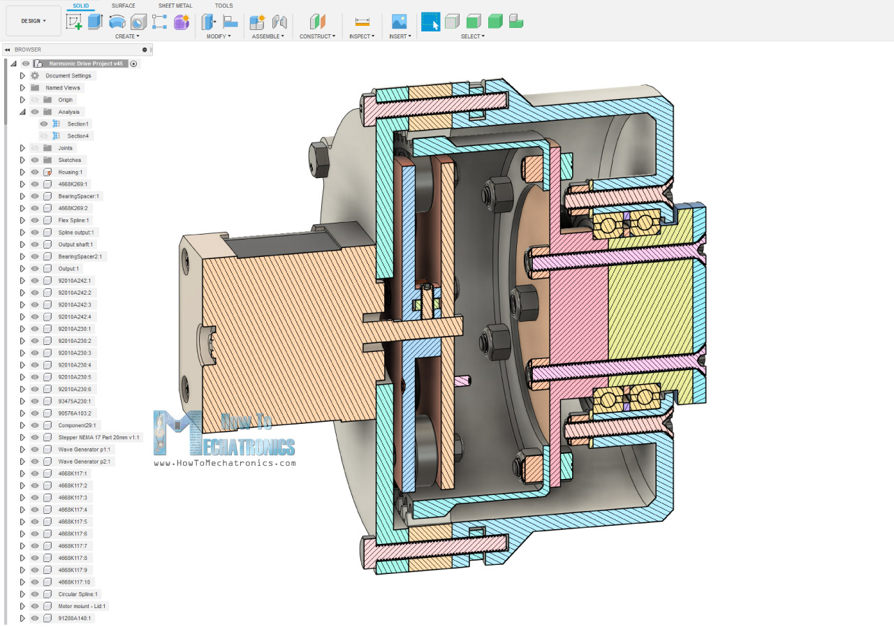
The rest of the parts are designed around these 3 key components. On the output side of the housing we will insert two bearings with 47mm outer diameter, and we will secure them with the help of some bolts and nuts.
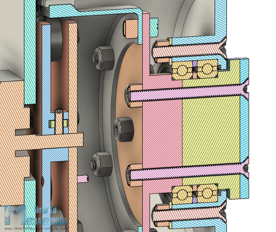
The output flange is made out of two parts connected with bolts and nuts so we can easily secure it to the two bearings.
STL files needed for 3D printing below.
You can download this 3D model, as well as explore it in your browser on Thangs.
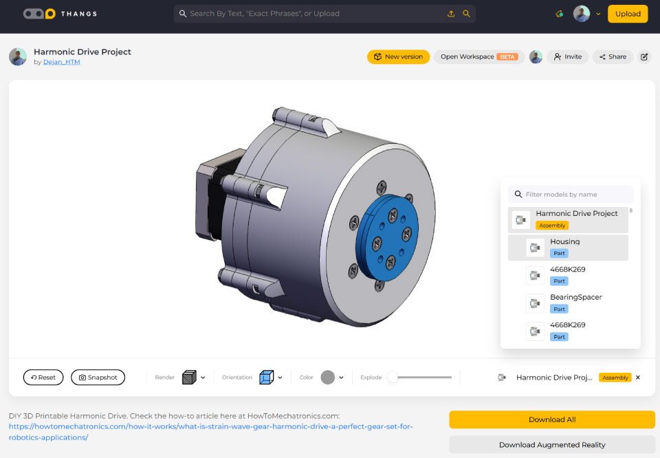
Download the 3D model at Thangs.
STL files needed for 3D printing:
See also: Best 3D Printers for Beginners and Makers [2021 Update]
3D Printed Strain Wave Gear – Harmonic Drive
Ok, it’s time to 3D print the parts now. When 3D printing the gears, it’s important to use the Horizontal Expansion feature in your slicing software.
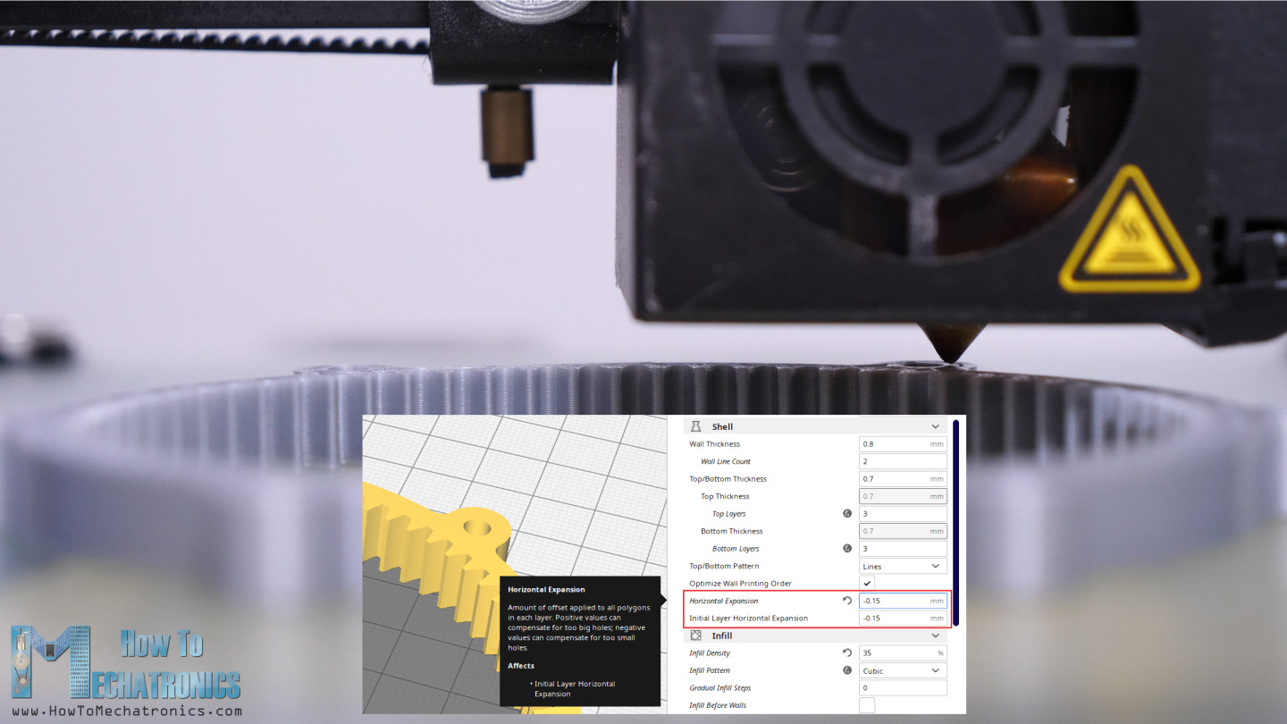
I set mine to -0.15mm and got relatively decent accuracy on the prints. Note that this might vary from printer to printer. If we don’t use this feature, the prints will be slightly bigger due to the expansion of the filament when printing, and the parts, or the gears won’t be able to mesh properly.
I used my Creality CR-10 3D printer for printing all of the parts, and I think it did good job considering its price point.
So, here are all 3D printed parts.
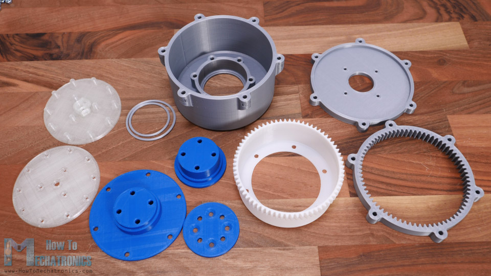
We just need some bolts, nuts and some bearings for completing the assembly of he Harmonic drive.
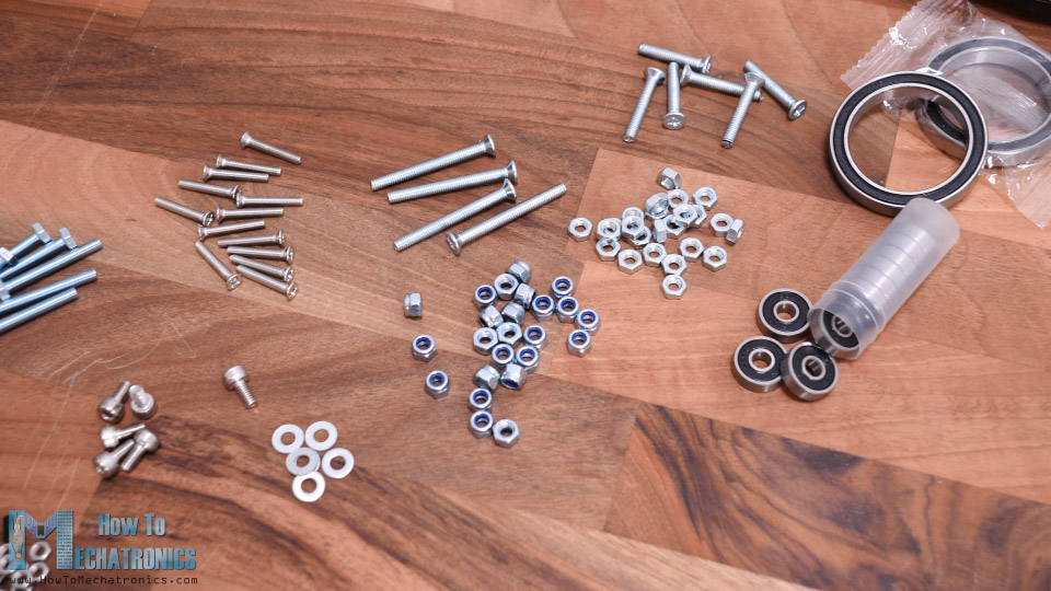
Here’s a complete list of all components:
- Bolts:
- M3x16 – 13 pieces
- M3x12 – 4
- M4x12 – 6
- M4x25 – 6
- M4x30 – 6
- M4x40 – 4
- Nuts:
- M3 self locking – 13
- M4 self locking – 16
- M4 – 10
- Bearings:
- (OD) 16mm x (IN) 5mm x (W) 5mm – 10 ………….. Amazon
- (OD) 47mm x (IN) 35mm x (W) 7mm – 2 ………….. Amazon
- Electronics:
- Stepper Motor – NEMA 17……………… Amazon / Banggood
- A4988 Stepper Driver…………………..… Amazon / Banggood
- Arduino ……………………………………..… Amazon / Banggood
- DC Power Supply …………………………. Amazon / Banggood
Disclosure: These are affiliate links. As an Amazon Associate I earn from qualifying purchases.
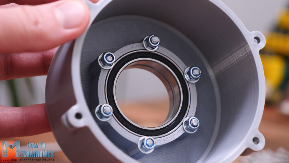
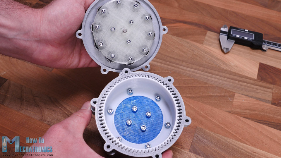
I started the assembling by inserting the two output bearings into the housing. The bearings have 47mm outer diameter and 35mm inner diameter. Like I said, I used -0.15mm Horizontal Expansion compensation when slicing the parts, so the bearings fitted quite tightly in the housing.
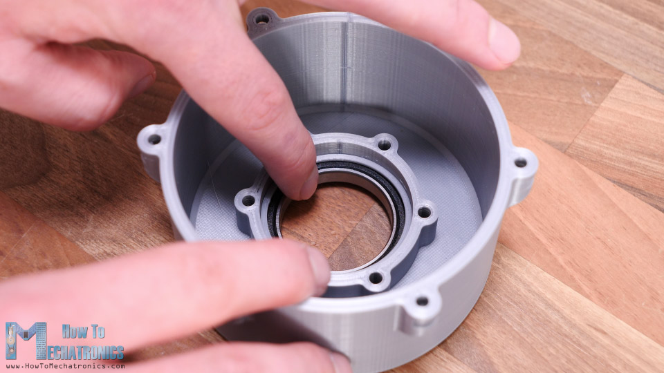
In between the two bearings I placed 1.5mm 3D printed distance rings. For securing the bearings to the housing we need six M4 countersunk bolts with 25mm length. We will also use M4 washers which will touch just enough the outer ring of the bearing and so they will keep the bearing secured to the housing.
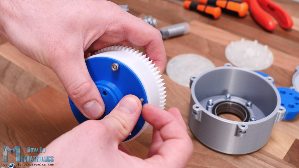
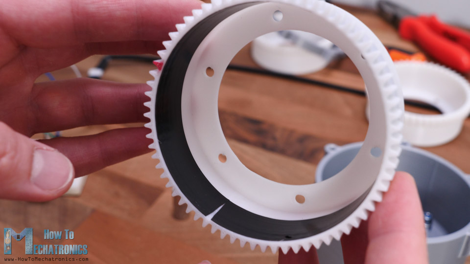
Next is the Flex spline. The walls of the cup are just 1.2mm tick so although it’s printed in PLA it’s still flexible at the open end.
On the closed end of the Flex spline we can attach the output flange using six M4 bolts. Once secured, the flex spline is now a bit less flexible then previously, but the close end is now quite rigid.
Next, we need to insert the flex spline through the bearing. The output flange goes half way through the first bearing. On the other side we will insert the other part of the output flange which will fit exactly between the two bearings.
I continued with placing four M4 nuts in the slots on the output shaft. These nuts will serve for attaching or connecting things to the output of the gear set.
To finish the output shaft, on top of this I placed another part which will cover the nuts, and using 4 M4 bolts with 40mm length I can finally secure the two output parts together. Now, the flex spline and the output shaft can freely while being secured to the housing.
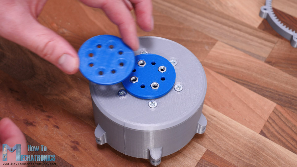
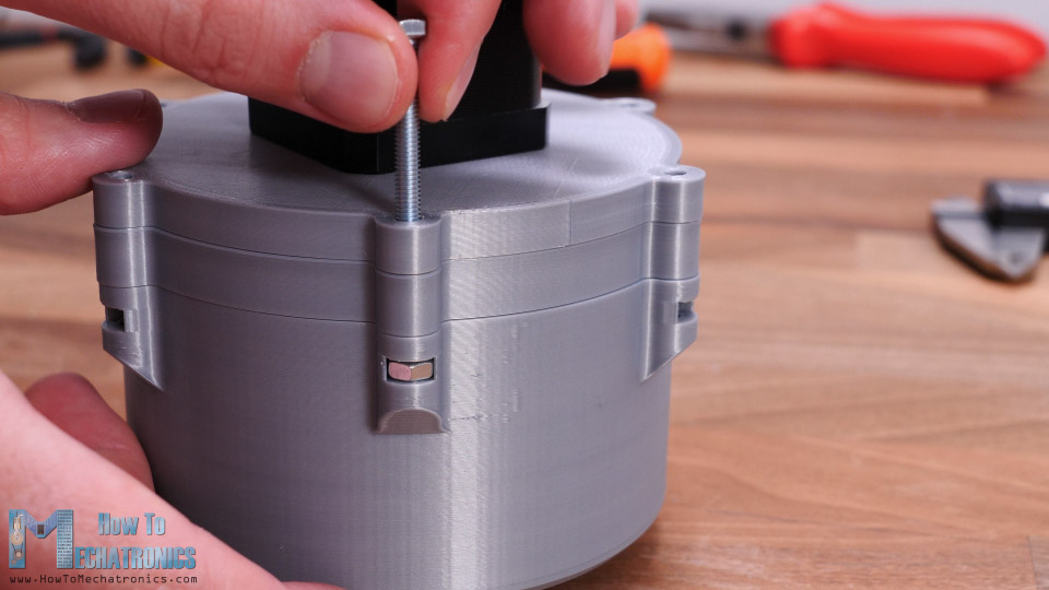
Ok, so next we have the circular spline which will be secured to the housing together with the gear set lid and motor mount. But before we do that, we need to assemble the wave generator. Here first we need to insert two M3 nuts. These nuts will serve for securing the wave generator to the motor shaft using two grub screws.
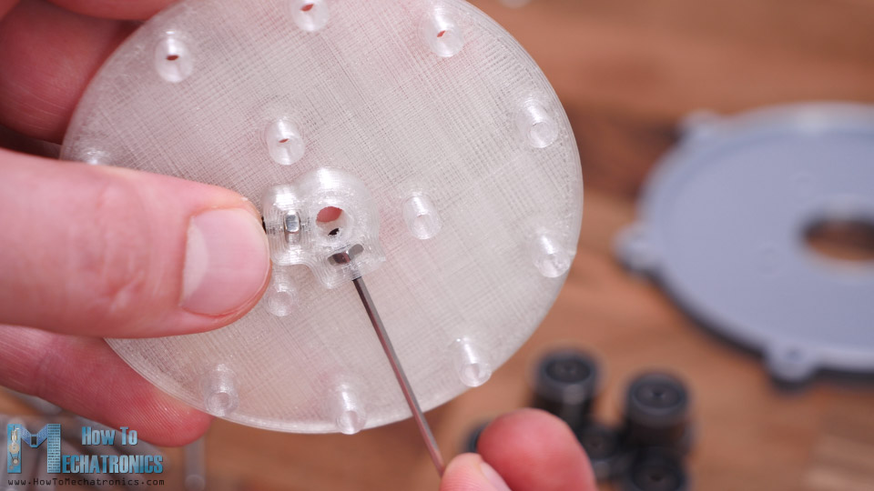
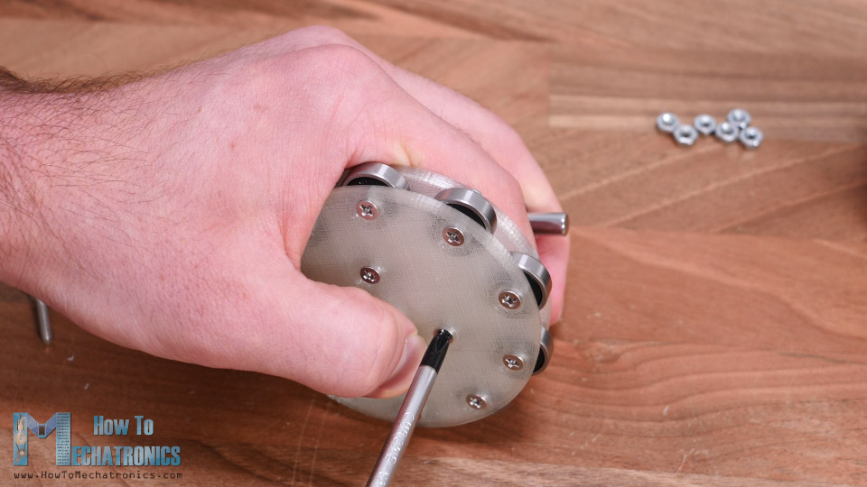
Next, we can start inserting the 10 bearings in place. We can notice here how the bearings are distanced from the wall just a little bit with the small edge at the bottom of the shafts. The other part of the wave generator also has such edges so the bearings won’t touch the wall. We are going to secure the bearings and actually the whole wave generator, with 16mm long M3 bolts and some nuts.
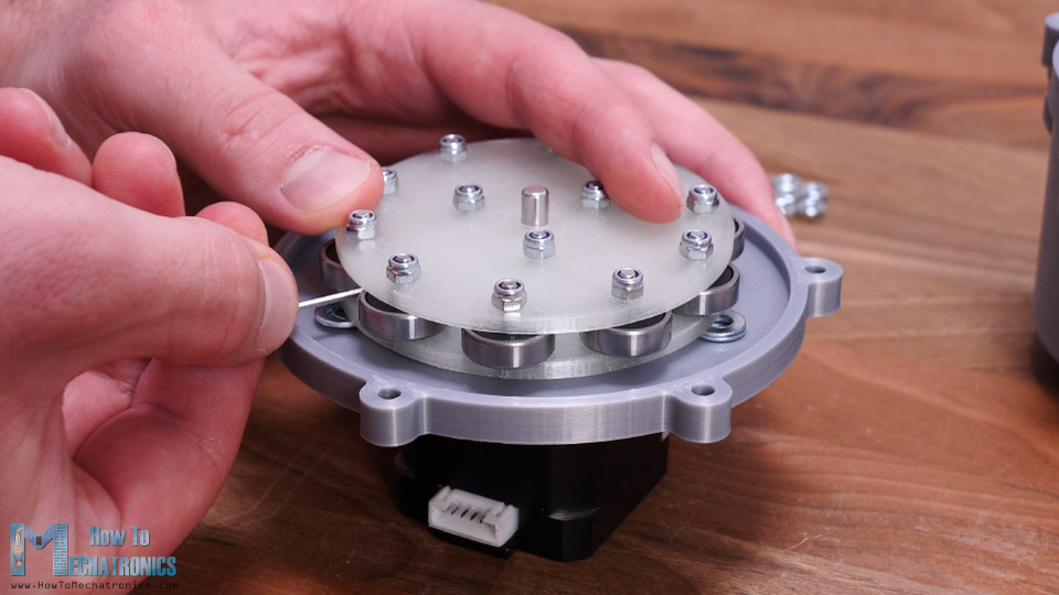
Next, we need to secure the wave generator to the motor, but before we do that, we need to attach the motor to the motor mount and the lid of the gear set. The wave generator should be 2mm apart from the motor lid, so I used two washers as guides when inserting wave generator in place. Then we just have to tighten the grub screws which are positioned in a way that they can be reached in between the bearings.
Finally, we can insert the wave generator into the flex spline and connect everything together. We should first adjust the flex spline to be meshed with the circular spline in an elliptical form and then insert wave generator in the same direction.
To be honest it can be a bit difficult make this fit because we don’t have a control over the flex spline because of the motor mount. I could have designed this a bit different but still I think it’s good enough for demonstrating purposes.
What’s left now is to insert M4 nuts in these housing sockets, and secure both the circular spline and the wave generator to the housing.
And that’s it, our Strain Wave Gear or Harmonic Drive is now done. But as I finished, I thought that completing the gear set like this is kind of boring because we can see nothing except a slow rotating output shaft. There, I decided to replace the 3D printed gear set lid with an acrylic one so we can also see what is going on inside.
I had a 4mm tick acrylic plate, so I marked the shape of the lid on it and using a hand saw I roughly cut the shape.
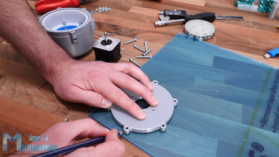
Then using a rasp, I fine-tuned the shape of the acrylic. I made the holes with a 3mm drill bit and the big hole for the motor with a 25mm Forstner bit. The shape came out pretty decent at the end.
I re-assembled the motor and the wave generator back as show earlier. We can note here that I added some nuts between the acrylic and the housing in order to get the proper distance as the lid had previously.
Now this gear set looks much cooler.
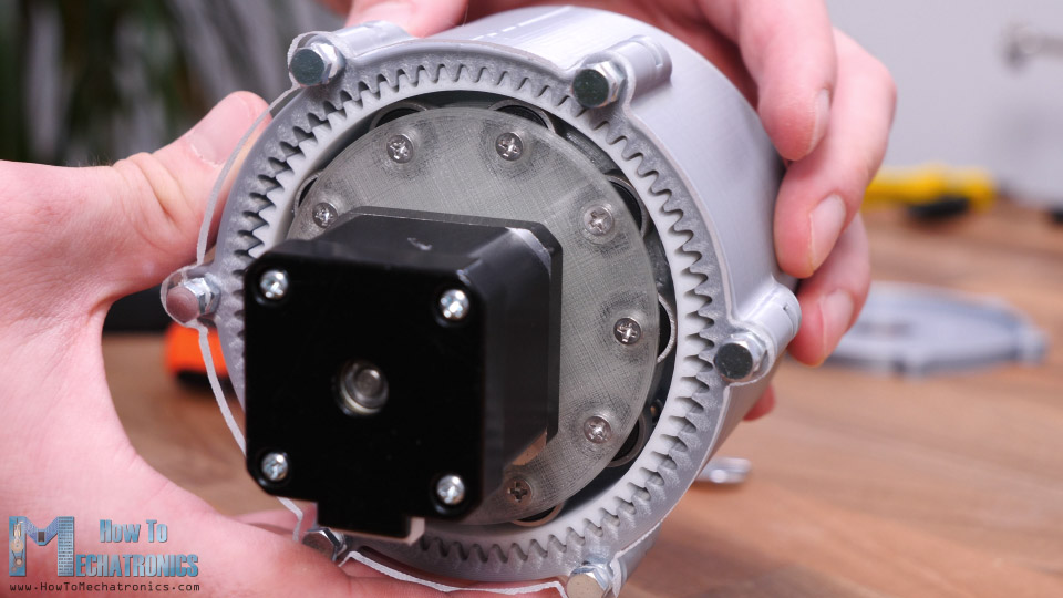
I connected the stepper motor to an Arduino so I can control the motor speed and direction to better examine and see how the system works.
So here it is. Now we can see how the Harmonic Drive works in real life. In this case, the output shaft is 35 times slower than the input shaft.
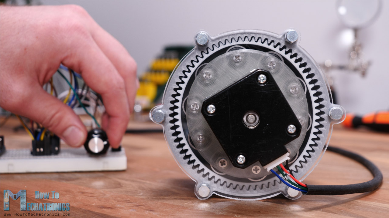
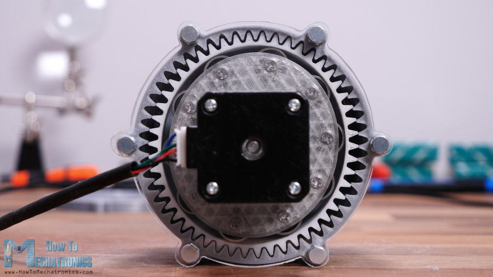
Here I marked one tooth of the flex spline with red color so we can better track it and get sense of the movement of the flex spline. To be honest it’s quite fun looking how this thing works.
However, we notice that the flex spline sometimes jitters or the motion is not that smooth. There are several reasons for that. In this configuration, the problem is that I made the acrylic motor mount by hand, so the motor is not mounted perfectly in the center. When using the original 3D printed motor mount, the movement is much smoother.
We can also notice that our Harmonic drive is far from having zero-backlash. That’s because of, like I said earlier, the limitations of these type 3D printers and how good they can print. It’s not just about how good the profile of the tooth can be printed, but also how accurate the overall dimensions are. For example, here I used an insulating tape on the inside of flax spline, which is only 0.18mm tick, and with it I got better results.
So, I guess, it’s all about testing and tweaking the prints to get better results. I also tried to print the gears with a module of 1.75, but I didn’t get good results.
Actually, when using the original 3D printed lid, the motion was smoother but still not good enough.
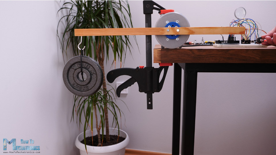
I also tried lifting some weights. At a distance of 25cm it was able to lift 1.25kg. That’s torque of around 3Nm, which is at least 10 times greater than what this NEMA 17 stepper motor is rated.
So that’s pretty much everything for this video. I would just add that this gearing system can be easily designed to have hollow shaft which is very handy for robotics applications. So, I might use Harmonic Drives in some of my future videos when making some robot projects.
I hope you enjoyed this video and learned something new. Don’t forget to subscribe and for more tutorials and projects, visit HowToMechatronics.com
Hi, great job!
I would like to download the model and make some changes, but it will be for academic purposes. Is it okay?. Of course, I will cite you properly.
Many thanks
Hey, thanks!
Sure, that’s fine.
Cheers!
Excellent project. I will print and use for our engineering folks as I am sure they have never even heard of this type of gearing system. Well done and excellent video and instructions.
Thanks, I’m glad to hear you found it interesting!
Great Job!!!
Which slicing SW have you used?
I used Cura slicing software.
How do you make the illustrations of your article so exquisite? Let’s teach us
I used Blender for the 3D animation and Fusion 360 for the 3D printed model design.