In this tutorial we will learn what is brushless DC motor or BLDC and how does it work. We will also cover how an Electronic Speed Controller or ESC work, an electronic circuit used for controlling brushless motors.
This is a two-part article, where in this first part we will learn the working principle of a brushless DC motor and ESC (Electronic Speed Controller), and in the second part we will learn how to control BLDC motor using Arduino.
You can watch the following video or read the written tutorial below.
What is Brushless DC Motor?
A brushless DC motor or BLDC is an electric motor powered by direct current and generates its motion without any brushes like in conventional DC Motors.
Brushless motors are more popular nowadays than conventional brushed DC motors because they have better efficiency, can deliver precise torque and rotation speed control, and offer high durability and low electrical noise, thanks to the lack of brushes.
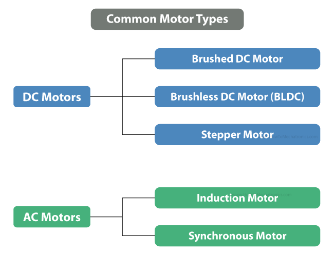
BLDC motors are used in applications where efficiency and longevity is required, like washing machines, air conditioners and other consumer electronics. Also they are used in spin hard disc drives, RC models like RC Airplane cars and so on.
How Brushless DC Motor Works?
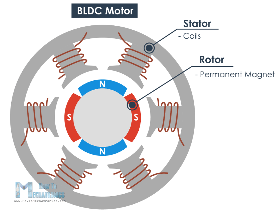
A brushless motor (BLDC) consist of two main parts, a stator and a rotor. For this illustration the rotor is a permanent magnet with two poles, while the stator consists of coils arranged as shown in the picture below.
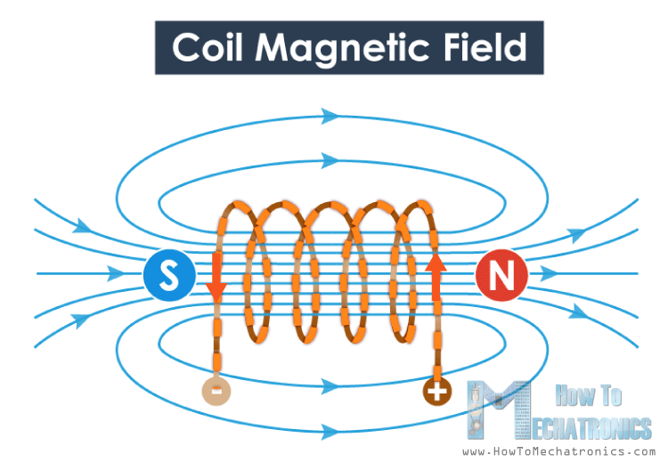
We all know that if we apply current through a coil it will generate a magnetic field and the magnetic field lines or the poles depends on the current direction.
So if we apply the appropriate current, the coil will generate a magnetic field that will attract the rotors permanent magnet. Now if we activate each coil one after another the rotor will keep rotating because of the force interaction between permanent and the electromagnet.
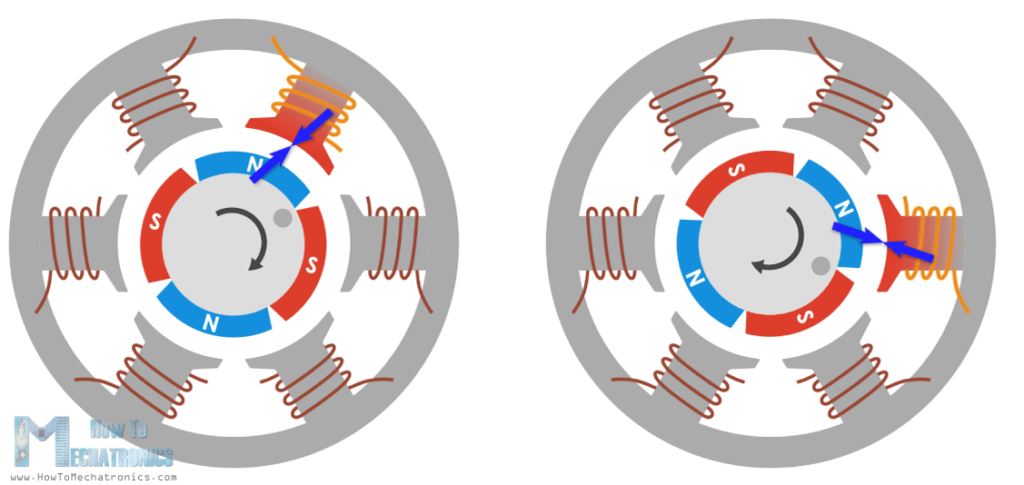
In order to increase the efficiency of the motor we can wind two opposite coils as a single coil in way that will generate opposite poles to the rotors poles, thus we will get double attraction force.
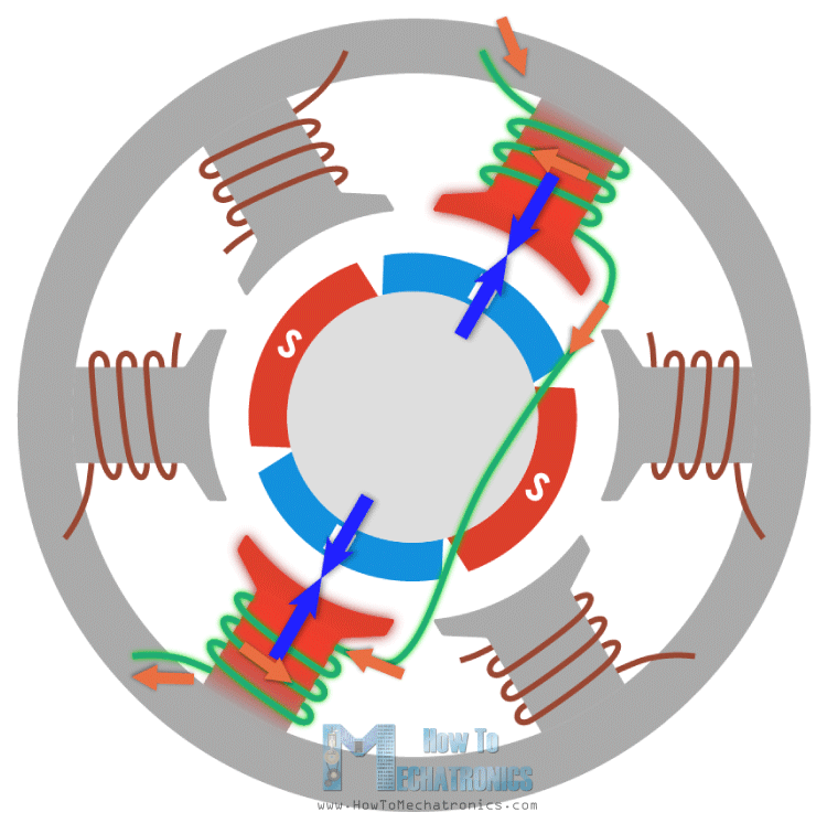
With this configuration we can generate the six poles on the stator with just three coils or phase. We can further increase the efficiency by energizing two coils at the same time. In that way one coil will attract and the other coil will repel the rotor.
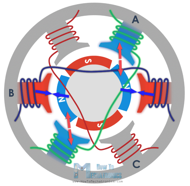
In order the rotor to make a full 360 degrees cycle, it need six steps or intervals.
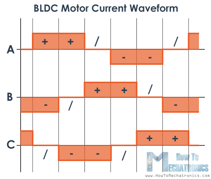
If we take a look at the current waveform we can notice that in each interval there is one phase with positive current, one phase with negative current and the third phase is turned off. This gives the idea that we can connect the free end points of each of the three phases together and so we can share the current between them or use a single current to energize the two phases at the same time.
Here’s an example. If we pull up phase A High, or connect it to the positive DC voltage, with some kind of switch, for example a MOSFET, and on the other side, connect the phase B to ground, then the current will flow from VCC, through phase A, the neutral point and phase B, to ground. So, with just a single current flow we generated the four different poles which cause the rotor to move.
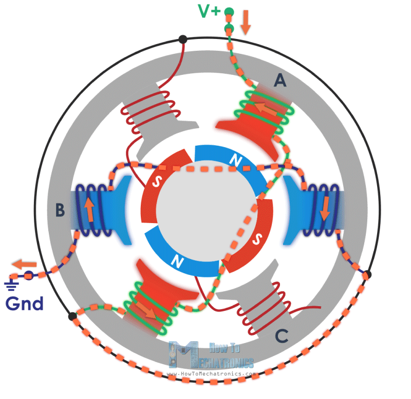
With this configuration we actually have a star connection of the motor phases, where the neutral point is internally connected and the other three ends of the phases come out of the motor and that’s why brushless motor have three wires coming out of it.
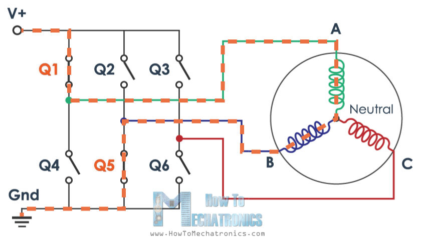
So, in order the rotor to make full cycle we just need to activate the correct two MOSFETS in each of the 6 interval and that’s what ESCs are actually all about.
See Also
How a Stepper Motor Works
How ESC Works (Electronic Speed Controller)
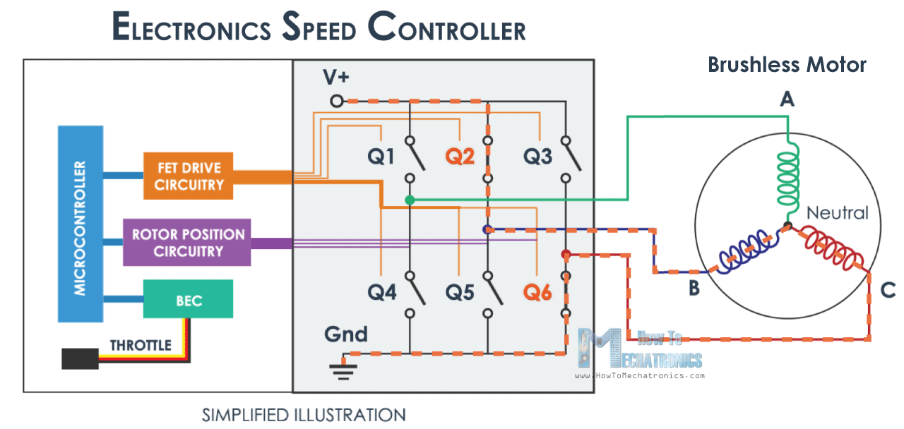
An ESC or an Electronic Speed Controller controls the brushless motor movement or speed by activating the appropriate MOSFETs to create the rotating magnetic field so that the motor rotates. The higher the frequency or the quicker the ESC goes through the 6 intervals, the higher the speed of the motor will be.
However, here comes an important question, and that’s how do we know when to activate which phase. The answer is that we need to know the position of the rotor and there are two common methods used for determining the rotor position.
The first common method is by using Hall-effect sensors embedded in the stator, arranged equally 120 or 60 degrees from each other.
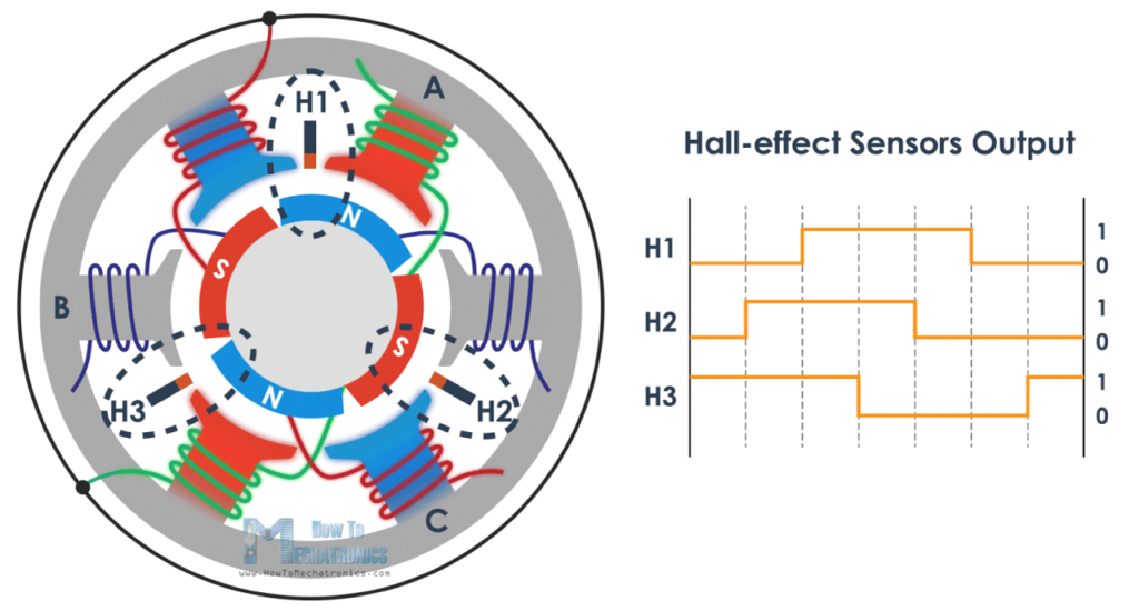
As the rotors permanent magnets rotate the Hall-effect sensors sense the magnetic field and generate a logic “high” for one magnetic pole or logic “low” for the opposite pole. According to this information the ESC knows when to activate the next commutation sequence or interval.
The second common method used for determining the rotor position is through sensing the back electromotive force or back EMF. The back EMF occurs as a result of the exact opposite process of generating a magnetic field or when a moving or changing magnetic field pass through a coil it induces a current in the coil.
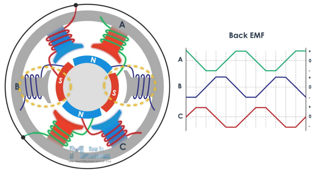
So, when the moving magnetic field of the rotor pass through the free coil, or the one that’s not active, it will induce a current flow in coil and as result a voltage drop will occur in that coil. The ESC captures these voltage drops as they occur and based on them it predicts or calculates when the next interval should take place.
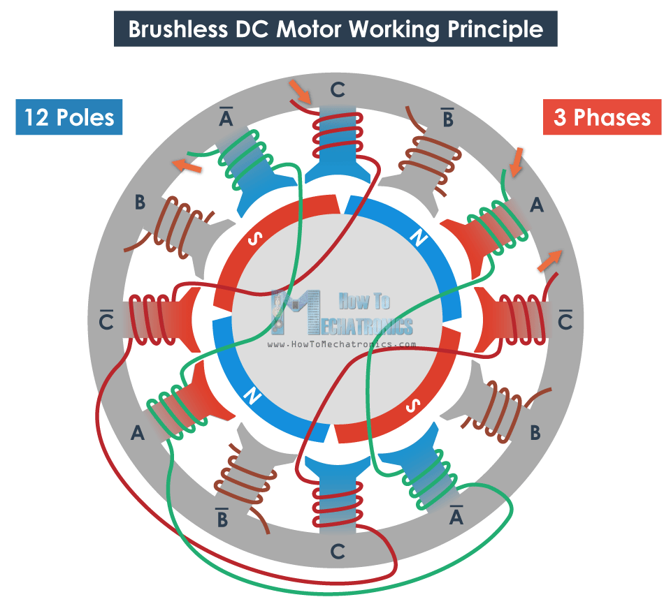
So that’s the basic working principle of brushless DC motors and ESCs and it’s the same even if we increase the number of poles of the both the rotor and the stator. We will still have a three-phase motor, only the number of intervals will increase in order to complete a full cycle.
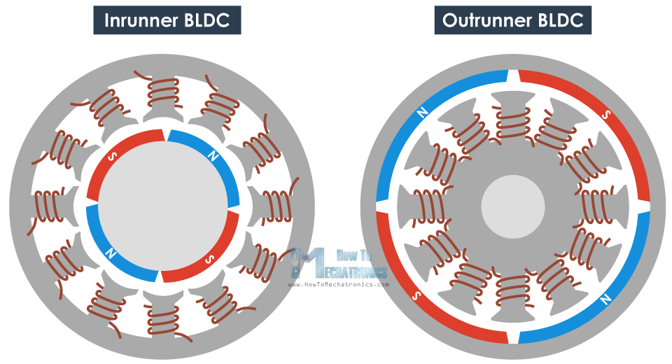
Here we can also mention that BLDC motors can be inrunners or outrunners. An inrunner brushless motor has the permanent magnets inside the electromagnets, and vice versa, an outrunner motor has the permanent magnets outside the electromagnets. Again, they use the same working principle and each of them has its own strengths or weaknesses.
Related: Stepper Motors and Arduino – The Ultimate Guide
Demonstrating How BLDC and ESC Work
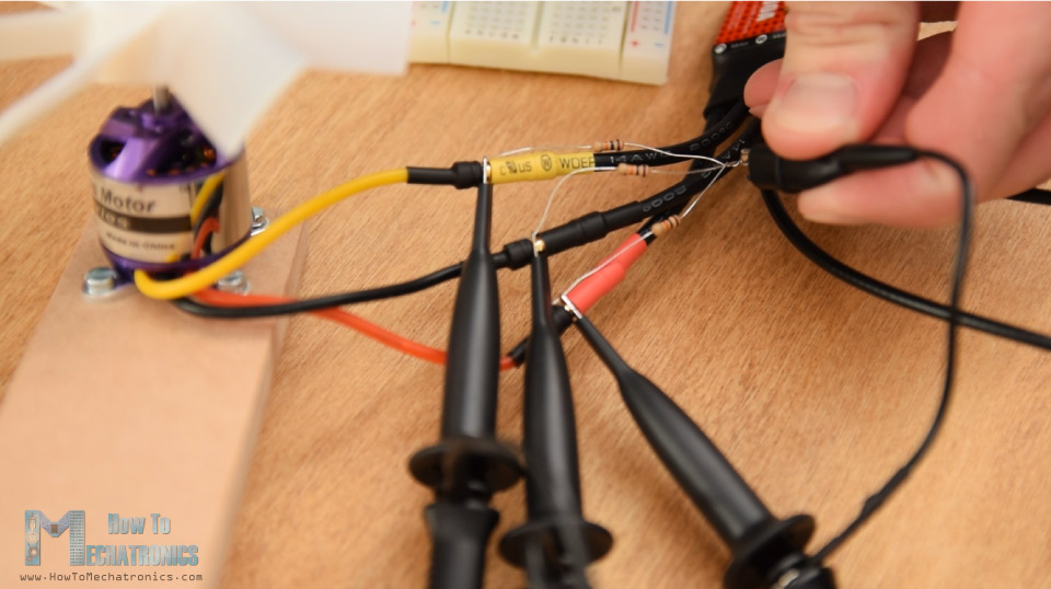
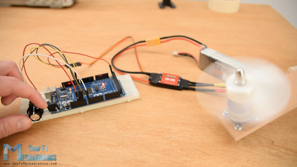
Ok, that’s enough theory so now let’s demonstrate and see in real life what we explained above. For that purpose we will we connect the three phases of a brushless motor to an oscilloscope. I connected 3 resistors in a single point to make a virtual neutral point and on the other side I connected them to the three phases of the BLDC motor.
The first thing that we can notice here are the three sine waves. These sine waves are actually the back EFM generated in the phases when they are not active.
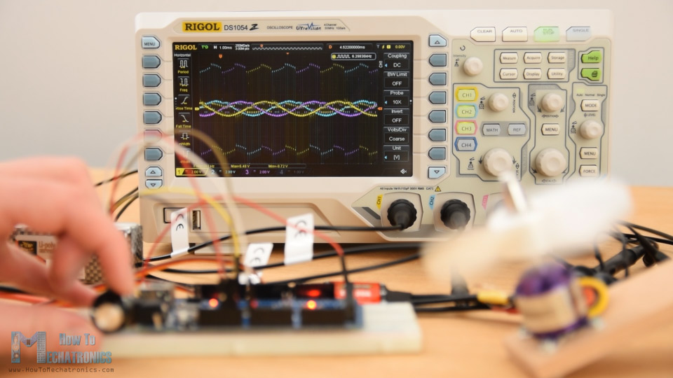
We can see that as we change the RPM of the motor, the frequency of the sine waves changes and as well as their amplitude. The higher the RPM, the higher are the frequency and the amplitude of the back EMF sine waves. However, what drives the motor are actually these peaks, which are the active phases that generate the changing magnetic field.
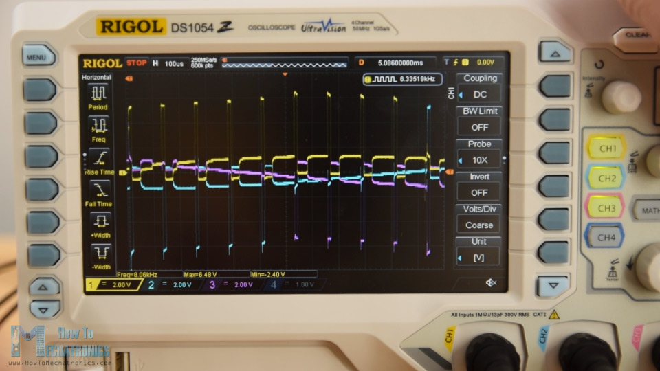
We can notice that at each interval, there are two active and one inactive phase. For example, here we have phase A and B active, while phase C is inactive. Then we have phase A and C active, while phase B is inactive, and so on.
Conclusion
So, we have covered the basic working principle of brushless motor and how it works in combination with an ESC. In case you want some more real live examples and learn how to control brushless motors using Arduino you should check the part two of this tutorial.
Here you can check some of my projects where I have used BLDC motors:
I hope you enjoyed this tutorial and learned something new . Feel free to ask any question in the comments section below and don’t forget to check my collection of Arduino Projects.
A super good article, simple and clear. I can do it myself
So helpful! Many thanks. Even my 11 year old understood (mostly).
Thanks Sir
I am about including BLDC in mz PhD Project and your video taught me alot
thanks alot and wish you all the best.
Very Good, I learned in a very easy and fun way things that seemed to be very complicated, thank you very much.
Thanks, I’m happy to hear that!