In this tutorial we will learn what is Hall Effect and how Hall Effect Sensors work. You can watch the following video or read the written tutorial below.
Overview
The Hall Effect is the most common method of measuring magnetic field and the Hall Effect sensors are very popular and have many contemporary applications. For example, they can be found in vehicles as wheel speed sensors as well as crankshaft or camshaft position sensors. Also they are often used as switches, MEMS compasses, proximity sensors and so on. Now we will go through some of these sensors and see how they work, but first let’s explain what is the Hall Effect.
What is Hall Effect?
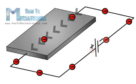
Here’s the experiment that explains the Hall Effect: If we have thin conductive plate, as illustrated, and we set current to flow through it, the charge carriers would flow in a straight line from one to the other side of the plate.
Now if we bring some magnetic field near the plate we would disturb the straight flow of the charge carriers due to a force, called Lorentz Force (Wikipedia). In such a case the electrons would deflect to one side of the plate and the positive holes to the other side of the plate. This means if we put a meter now between the other two sides we will get some voltage which can be measured.
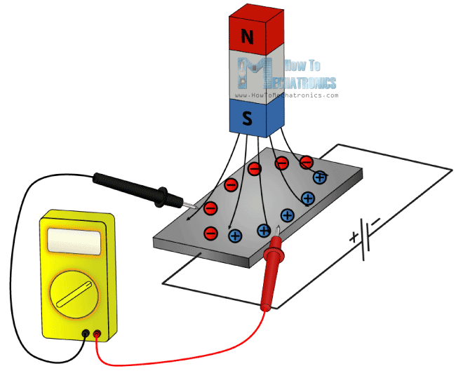
So the effect of getting a measurable voltage, as we explained above, is called the Hall Effect after Edwin Hall who discovered it in 1879.
Hall Effect Sensors
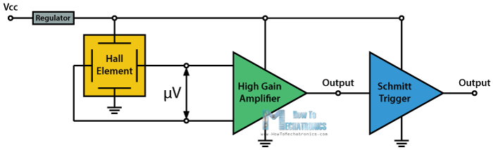
The basic Hall Element of the Hall Effect magnetic sensors mostly provides very small voltage of only a few micro volts per Gauss, so therefore, these devices are usually manufactured with built-in high gain amplifiers.
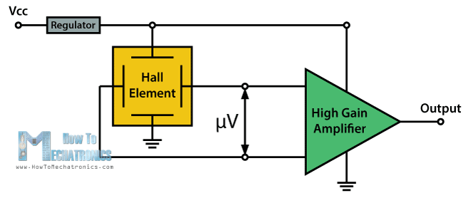
There are two types of Hall Effect sensors, one providing analog and the other digital output. The analog sensor is composed of a voltage regulator, a Hall Element and an amplifier. From the circuit schematics we can see that the output of the sensor is analog and proportional to the Hall Element output or the magnetic field strength. These type of sensors are suitable and used for measuring proximity because of their continuous linear output.
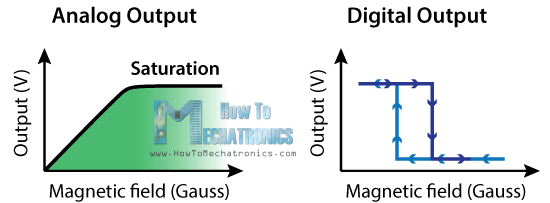
On the other hand, the digital output sensors provide just two output states, either “ON” or “OFF”. These type of sensors have an additional element, as illustrated in the circuit schematics. That’s the Schmitt Trigger which provides hysteresis or two different thresholds levels so the output is either high or low. For more details how the Schmitt Trigger works, you can check my particular tutorial for that.
An example of this type of sensor is the Hall Effect switch. They are often used as limit switches, for example in 3D printers and CNC Machines, as well as for detection and positioning in industrial automation systems.
Other contemporary applications of the these sensors are measuring wheel/ rotor speed or RPM as well as determining position of crankshaft or camshaft in engine systems. These sensors are composed of a Hall Element and a permanent magnet which are placed near a toothed disk attached on the rotating shaft.
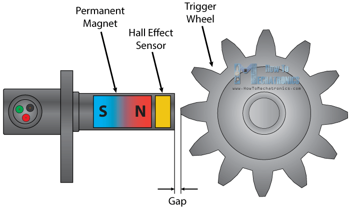
The gap between the sensor and the teeth of the disk is very small so each time a tooth pass near the sensor it changes the surrounding magnetic field which will cause the output of the sensor to go either high or low. So the output of the sensor is a square wave signal which can be easily used for calculating the RPM of the rotating shaft.
Your explanation is quite comprehensible and useful. I would like to ask your permission to extract and publish 3 of the figures in a textbook I plan to edit. I am looking forward to hearing from you soon. Thank you very much for your cooperation.
Glad to hear it you found it useful. Sure have a permission.
Thank you, clearly understood.
I sure appreciate the sharing of experience of these insight fullness tutoring on electronics.
all the projects are very useful and can easily unterstandable….thanks