In this tutorial we will learn how the MEMS accelerometer, gyroscope and magnetometer work and how to use them with the Arduino Board. Also with the Processing IDE we will make some practical applications using the sensors. You can watch the following video or read the written tutorial below.
What is MEMS?
The MEMS are very small systems or devices, composed of micro components ranging from 0.001 mm to 0.1 mm in size. These components are made of silicon, polymers, metals and/or ceramics, and they are usually combined with a CPU (Microcontroller) for completing the system.
Now we will briefly explain how each of these Micro-Electro-Mechanical-Systems (MEMS) sensors work.
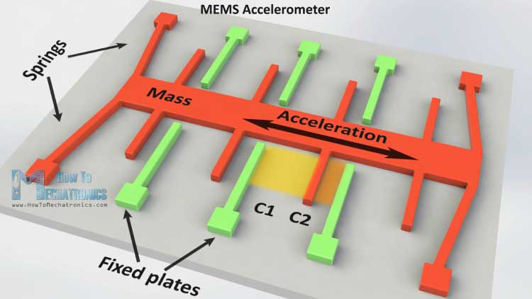
MEMS Accelerometer
It measures acceleration by measuring change in capacitance. Its micro structure looks something like this. It has a mass attached to a spring which is confined to move along one direction and fixed outer plates. So when an acceleration in the particular direction will be applied the mass will move and the capacitance between the plates and the mass will change. This change in capacitance will be measured, processed and it will correspond to a particular acceleration value.
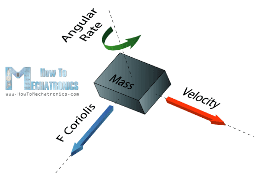
MEMS Gyroscope
The gyroscope measures angular rate using the Coriolis Effect. When a mass is moving in a particular direction with a particular velocity and when an external angular rate will be applied as show with the green arrow a force will occur, as show with the blue red arrow, which will cause perpendicular displacement of the mass. So similar to the accelerometer, this displacement will cause change in capacitance which will be measured, processed and it will correspond to a particular angular rate.
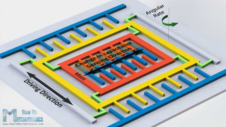
The micro structure of the gyroscope looks something like this. A mass that is constantly moving, or oscillating, and when the external angular rate will be applied a flexible part of the mass would move and make the perpendicular displacement.
MEMS Magnetometer
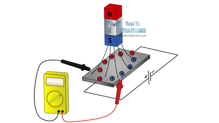
It measures the earth magnetic field by using Hall Effect or Magneto Resistive Effect. Actually almost 90% of the sensors on the market use the Hall Effect and here’s how it works.
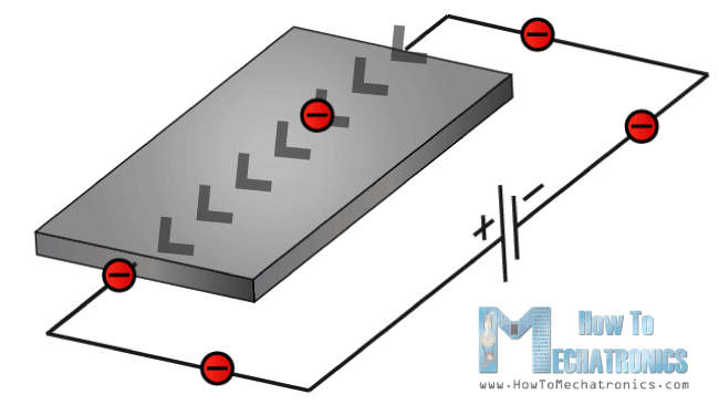
If we have a conductive plate like shown in the photo and we set current to flow through it, the electrons would flow straight from one to the other side of the plate. Now if we bring some magnetic field near the plate we would disturb the straight flow and the electrons would deflect to one side of the plate and the positive poles to the other side of the plate. That means if we put a meter now between these two sides we will get some voltage which depends from the magnetic field strength and its direction.
The other 10% of the sensors on the market use the Magneto-resistive Effect. These sensors use materials that are sensitive to the magnetic field, usually composed of Iron (Fe) and Nickel (Ne). So when these materials are exposed to magnetic field they change their resistance.
Arduino and MEMs sensors
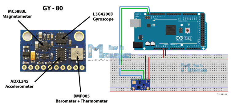
Ok now let’s connect these sensors to the Arduino Board and make some use of them. As an example I will use the GY-80 breakout board which has the following sensors: ADXL345 3 Axis Accelerometer, L3G4200D 3 Axis Gyroscope, MC5883L 3 Axis Magnetometer and also a Barometer and a Thermometer which we won’t use in this tutorial.
You can get these components from any of the sites below:
- ADXL345 3-Axis Accelerator……………………………………………………… Amazon / Banggood / AliExpress
- 2 in 1: MPU6050 6-Axis Gyroscope & Accelerometer ………………… Amazon / Banggood / AliExpress
- 3 in 1: GY-80 9-Axis Magnetic Field Acceleration Gyroscope……… Amazon
- 3 in 1: GY-86 10DOF MS5611 HMC5883L MPU6050 Module……… Banggood / AliExpress
Disclosure: These are affiliate links. As an Amazon Associate I earn from qualifying purchases.
This board use the I2C communication protocol which means that we can use all sensors with just two wires. So in order to make the communication between the Arduino and the sensors we need to know their unique device addresses and their internal register addresses for getting the data out of them. These addresses can be found from the datasheets of the sensors:
For more details how the I2C communication works you can check my other I2C Communication Protocol Tutorial.
Source Code
Now let’s see the codes for getting the data from the sensors. We will start with the accelerometer and there will be some explanation before each code, as well as some additional description in the comments of the code .
Arduino Accelerometer Code
First we need to include the Arduino Wire Library and define the registers addresses of the sensor. In the setup section we need to initiate the Wire Library and start the serial communication as we will use the serial monitor for showing the results. Also here we need to activate the sensor, or enable the measurement by sending appropriate byte to the Power_CTL register and here’s how we do that. Using the Wire.beginTransmission() function we select to which sensor we will talk, the 3-Axis Accelerometer in this case. Then using the Wire.write() function we tell to which internal register we will talk. After this we will send the appropriate byte for enabling the measurement. Using the Wire.endTransmission() function we will end the transmission and that will transmit the data to the registers.
In the loop section we need to read the data for each axis. We will start with the X – Axis. So first we will select to which registers we will talk, the two X – Axis internal registers in this case. Then using the Wire.requestFrom() function we will request the transmitted data or the two bytes from the two registers. The Wire.available() function will return the number of bytes available for retrieval and if that number match with our requested bytes, in our case 2 bytes, using the Wire.read() function we will read the bytes from the two registers of the X axis.
The output data from the registers is two’s complement, with X0 as the least significant byte and X1 as the most significant byte so we need to convert these bytes into float values from -1 to +1 depending on the direction of the X – Axis relative to the Earth acceleration or the gravity. We will repeat this procedure for the two other axis and at the end we will print these values on the serial monitor.
#include <Wire.h>

//--- Accelerometer Register Addresses
#define Power_Register 0x2D
#define X_Axis_Register_DATAX0 0x32 // Hexadecima address for the DATAX0 internal register.
#define X_Axis_Register_DATAX1 0x33 // Hexadecima address for the DATAX1 internal register.
#define Y_Axis_Register_DATAY0 0x34
#define Y_Axis_Register_DATAY1 0x35
#define Z_Axis_Register_DATAZ0 0x36
#define Z_Axis_Register_DATAZ1 0x37

int ADXAddress = 0x53;  //Device address in which is also included the 8th bit for selecting the mode, read in this case.

int X0,X1,X_out;
int Y0,Y1,Y_out;
int Z1,Z0,Z_out;
float Xa,Ya,Za;

void setup() {
  Wire.begin(); // Initiate the Wire library
  Serial.begin(9600);
  delay(100);

  Wire.beginTransmission(ADXAddress);
  Wire.write(Power_Register); // Power_CTL Register
  // Enable measurement
  Wire.write(8); // Bit D3 High for measuring enable (0000 1000)
  Wire.endTransmission();
}

void loop() {
  // X-axis
  Wire.beginTransmission(ADXAddress); // Begin transmission to the Sensor
  //Ask the particular registers for data
  Wire.write(X_Axis_Register_DATAX0);
  Wire.write(X_Axis_Register_DATAX1);
  Wire.endTransmission(); // Ends the transmission and transmits the data from the two registers
  Wire.requestFrom(ADXAddress,2); // Request the transmitted two bytes from the two registers
  if(Wire.available()<=2) {  //
    X0 = Wire.read(); // Reads the data from the register
    X1 = Wire.read();
    /* Converting the raw data of the X-Axis into X-Axis Acceleration
     - The output data is Two's complement
     - X0 as the least significant byte
     - X1 as the most significant byte */
    X1=X1<<8;
    X_out =X0+X1;
    Xa=X_out/256.0; // Xa = output value from -1 to +1, Gravity acceleration acting on the X-Axis
  }
  // Y-Axis
  Wire.beginTransmission(ADXAddress);
  Wire.write(Y_Axis_Register_DATAY0);
  Wire.write(Y_Axis_Register_DATAY1);
  Wire.endTransmission();
  Wire.requestFrom(ADXAddress,2);
  if(Wire.available()<=2) {
    Y0 = Wire.read();
    Y1 = Wire.read();
    Y1=Y1<<8;
    Y_out =Y0+Y1;
    Ya=Y_out/256.0;
  }
  // Z-Axis
  Wire.beginTransmission(ADXAddress);
  Wire.write(Z_Axis_Register_DATAZ0);
  Wire.write(Z_Axis_Register_DATAZ1);
  Wire.endTransmission();
  Wire.requestFrom(ADXAddress,2);
  if(Wire.available()<=2) {
    Z0 = Wire.read();
    Z1 = Wire.read();
    Z1=Z1<<8;
    Z_out =Z0+Z1;
    Za=Z_out/256.0;
  }
  // Prints the data on the Serial Monitor
  Serial.print("Xa= ");
  Serial.print(Xa);
  Serial.print("   Ya= ");
  Serial.print(Ya);
  Serial.print("   Za= ");
  Serial.println(Za);
}
Code language: PHP (php)
Arduino Gyroscope Code
For getting the data from the gyroscope we will have a similar code as the previous one. So first we have to define the register addresses and some variables for the data. In the setup section we have to wake up and put the sensor in normal mode using the CTRL_REG1 and also select the sensitivity of the sensor. For this example I will select the 2000dps sensitivity mode.
In the loop section similar to the accelerometer we will read the data for the X, Y and Z axis. Then the raw data has to be converted into angle values. From the datasheet of the sensor we can see that for the 2000dps sensitivity mode corresponds a 70 mdps/digit unit. This means that we have to multiply the raw output data by 0.07 in order to get the angular rate in degrees per second. Then if multiply the angular rate by time it will give us the angle value. So we need to calculate the time interval of each loop section and we can do that by using the millis() function at the top and the bottom of the loop section, and we will store its value into this “dt” variable. So for each executed loop we will calculate the angle and add it to the final angle value. We will do the same for the two other axis and at the end we will print the results in the serial monitor.
#include <Wire.h>

//--- Gyro Register Addresses
#define Gyro_gX0 0x28
#define Gyro_gX1 0x29
#define Gyro_gY0 0x2A
#define Gyro_gY1 0x2B
#define Gyro_gZ0 0x2C
#define Gyro_gZ1 0x2D

int Gyro = 0x69; //Device address in which is also included the 8th bit for selecting the mode, read in this case.

int gX0, gX1, gX_out;
int gY0, gY1, gY_out;
int gZ0, gZ1, gZ_out;
float Xg,Yg,Zg;
float angleX,angleY,angleZ,angleXc,angleYc,angleZc;


unsigned long start, finished, elapsed;
float dt=0.015;

void setup()
{
  Wire.begin();
  Serial.begin(9600);
  delay(100);

  Wire.beginTransmission(Gyro);
  Wire.write(0x20); // CTRL_REG1 - Power Mode
  Wire.write(15);   // Normal mode: 15d - 00001111b
  Wire.endTransmission();

  Wire.beginTransmission(Gyro);
  Wire.write(0x23); // CTRL_REG4 - Sensitivity, Scale Selection
  Wire.write(48);   // 2000dps: 48d - 00110000b
  Wire.endTransmission();
}

void loop()
{
  start=millis();
  //---- X-Axis
  Wire.beginTransmission(Gyro); // transmit to device
  Wire.write(Gyro_gX0);
  Wire.endTransmission();
  Wire.requestFrom(Gyro,1);
  if(Wire.available()<=1)
  {
    gX0 = Wire.read();
  }
  Wire.beginTransmission(Gyro); // transmit to device
  Wire.write(Gyro_gX1);
  Wire.endTransmission();
  Wire.requestFrom(Gyro,1);
  if(Wire.available()<=1)
  {
    gX1 = Wire.read();
  }

  //---- Y-Axis
  Wire.beginTransmission(Gyro); // transmit to device
  Wire.write(Gyro_gY0);
  Wire.endTransmission();
  Wire.requestFrom(Gyro,1);
  if(Wire.available()<=1)
  {
    gY0 = Wire.read();
  }
  Wire.beginTransmission(Gyro); // transmit to device
  Wire.write(Gyro_gY1);
  Wire.endTransmission();
  Wire.requestFrom(Gyro,1);
  if(Wire.available()<=1)
  {
    gY1 = Wire.read();
  }

  //---- Z-Axis
  Wire.beginTransmission(Gyro); // transmit to device
  Wire.write(Gyro_gZ0);
  Wire.endTransmission();
  Wire.requestFrom(Gyro,1);
  if(Wire.available()<=1)
  {
    gZ0 = Wire.read();
  }
  Wire.beginTransmission(Gyro); // transmit to device
  Wire.write(Gyro_gZ1);
  Wire.endTransmission();
  Wire.requestFrom(Gyro,1);
  if(Wire.available()<=1)
  {
    gZ1 = Wire.read();
  }

  //---------- X - Axis

  // Raw Data
  gX1=gX1<<8;
  gX_out =gX0+gX1;

  // From the datasheet: 70 mdps/digit
  Xg=gX_out*0.07; // Angular rate
  // Angular_rate * dt = angle
  angleXc = Xg*dt;
  angleX = angleX + angleXc;

  //---------- Y - Axis
  gY1=gY1<<8;
  gY_out =gY0+gY1;
  Yg=gY_out*0.07;
  angleYc = Yg*dt;
  angleY = angleY + angleYc;

  //---------- Z - Axis
  gZ1=gZ1<<8;
  gZ_out =gZ0+gZ1;
  Zg=gZ_out*0.07;
  angleZc = Zg*dt;
  angleZ = angleZ + angleZc;


  // Prints the data on the Serial Monitor
  Serial.print("angleX= ");
  Serial.print(angleX);
  Serial.print("   angleY= ");
  Serial.print(angleY);
  Serial.print("   angleZ= ");
  Serial.println(angleZ);

  delay(10);
  // Calculating dt
  finished=millis();
  elapsed=finished-start;
  dt=elapsed/1000.0;
  start = elapsed = 0;

}Code language: PHP (php)
Arduino Magnetometer Code
Again we will use a similar technique to the previous one. First we need to define the registers addresses and it the setup section set the sensor in continuous measurement mode. In the loop section we will get the raw data for each axis with the same method as for the previous sensors.
Then we need to convert the raw data into magnetic field value or Gauss units. From the datasheet of the sensor we can see that the default sensitivity mode is 0.92mG/digit. That means we need to multiply the raw data by 0.00092 in order to get the earth magnetic field in Gauss units. At the end we will print the values on the serial monitor.
#include <Wire.h> //I2C Arduino Library
#define Magnetometer_mX0 0x03
#define Magnetometer_mX1 0x04
#define Magnetometer_mZ0 0x05
#define Magnetometer_mZ1 0x06
#define Magnetometer_mY0 0x07
#define Magnetometer_mY1 0x08
int mX0, mX1, mX_out;
int mY0, mY1, mY_out;
int mZ0, mZ1, mZ_out;
float Xm,Ym,Zm;
#define Magnetometer 0x1E //I2C 7bit address of HMC5883
void setup(){
//Initialize Serial and I2C communications
Serial.begin(9600);
Wire.begin();
delay(100);
Wire.beginTransmission(Magnetometer);
Wire.write(0x02); // Select mode register
Wire.write(0x00); // Continuous measurement mode
Wire.endTransmission();
}
void loop(){
//---- X-Axis
Wire.beginTransmission(Magnetometer); // transmit to device
Wire.write(Magnetometer_mX1);
Wire.endTransmission();
Wire.requestFrom(Magnetometer,1);
if(Wire.available()<=1)
{
mX0 = Wire.read();
}
Wire.beginTransmission(Magnetometer); // transmit to device
Wire.write(Magnetometer_mX0);
Wire.endTransmission();
Wire.requestFrom(Magnetometer,1);
if(Wire.available()<=1)
{
mX1 = Wire.read();
}
//---- Y-Axis
Wire.beginTransmission(Magnetometer); // transmit to device
Wire.write(Magnetometer_mY1);
Wire.endTransmission();
Wire.requestFrom(Magnetometer,1);
if(Wire.available()<=1)
{
mY0 = Wire.read();
}
Wire.beginTransmission(Magnetometer); // transmit to device
Wire.write(Magnetometer_mY0);
Wire.endTransmission();
Wire.requestFrom(Magnetometer,1);
if(Wire.available()<=1)
{
mY1 = Wire.read();
}
//---- Z-Axis
Wire.beginTransmission(Magnetometer); // transmit to device
Wire.write(Magnetometer_mZ1);
Wire.endTransmission();
Wire.requestFrom(Magnetometer,1);
if(Wire.available()<=1)
{
mZ0 = Wire.read();
}
Wire.beginTransmission(Magnetometer); // transmit to device
Wire.write(Magnetometer_mZ0);
Wire.endTransmission();
Wire.requestFrom(Magnetometer,1);
if(Wire.available()<=1)
{
mZ1 = Wire.read();
}
//---- X-Axis
mX1=mX1<<8;
mX_out =mX0+mX1; // Raw data
// From the datasheet: 0.92 mG/digit
Xm = mX_out*0.00092; // Gauss unit
//* Earth magnetic field ranges from 0.25 to 0.65 Gauss, so these are the values that we need to get approximately.
//---- Y-Axis
mY1=mY1<<8;
mY_out =mY0+mY1;
Ym = mY_out*0.00092;
//---- Z-Axis
mZ1=mZ1<<8;
mZ_out =mZ0+mZ1;
Zm = mZ_out*0.00092;
//Print out values of each axis
Serial.print("x: ");
Serial.print(Xm);
Serial.print(" y: ");
Serial.print(Ym);
Serial.print(" z: ");
Serial.println(Zm);
delay(50);
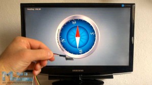
}Code language: PHP (php)Here’s a cool looking application of the sensor, a MEMS digital compass, made using the Processing IDE. You can find more details and the source code of this example on the following link:
Hi!
Found Your video on Youtube as I was researching how to implement the accelerometer and gyroscope to my car to get a detailed reading and make a AWD controller with it.
However, there is one question which bothers me:
What if You set this module to a flat (e.g. waterlevel) surface, switch the sensor off, move the sensor to a, for example 45° surface and power it back on.
If i understand Your “working principle” explanation correctly, the used sensor should be able to recognize this change (as the internal structure is always “moving”) and show the correct values after powering it back on again.
Is my assumption correct?
Reason for asking is, as mentioned above, I will be implementing this sensor in the car and for that it needs to be “intelligent” as usually you cannot always park it on a perfectly flat surface, so if the sensor is going to be used to control something, it always needs to know the absolute position of the car and must not reset itself to “0” everytime it is powered back on.
I hope the question is somehow understandable.
Thanks!
BR
RoB
Hey, well yes, the accelerometer senses the gravitational force, so anytime you power the device it will give you the correct result.
On the other side, the gyroscope senses the angular movement/ rate, which happens internally and depends on the sensor itself only. This means it won’t give your the correct result when powered on while being positioned at 45°. But still they can work combined and give you the correct result of programmed properly.
Great article thank you for sharing this! I’m planning to do a project to capture hand position and read out the data. The problem is that I need that while in movement so I thought I fix the sensor steady on the hand. I would need an arduino with battery in this case since i will be moving around in different positions and height. Do you think this possible using such devices you just presented in this article? Best!
Thanks. Sure, such an idea is possible with this kind of sensors and the Arduino. Check my Mechatronics Final Year Project.
I will, thank you for your reply!
I really appreciate your help in understanding how this module works but I think there is a problem with your low pass filter when you are heading close to North. Lets say for example I am on a course of about 2 degrees and the next reading is 355 degrees the low pass filter is going to take 85% of the current direction about 1.7 and add 15% of the latest heading (355 * 15/200) about 53 and claim the smoothed heading is now 54.7. This is very different to the real heading and can cause some serious navigation issues.
Hello dejan !
You really helped me a lot.But there is a question that I couldn’t do
You wrote a 0.07 for gyro.i’m using itg3200. where can I find 0.07 value for itg3200.
Thanks. I found that value from the datasheet of the sensor, so you should do that the same.
Hello,
Thank you for the clear description of the module and the code.
I exactly copied the code for the accelerator code, but it give me values for X and Y between 0 and -2, instead of 1 and -1. The Z does almost nothing.
I also printed the X0 and X1. X0 is between 0 and 2xx and the X1 is -512 or -256.
For the Y it is the same. Is this correct or is my GY-80 broken, because the Z is not working as in your demo.
Thanks in advance, Regards Goos
I
Hi there,
Try to read the X0 and X1 values in a separate “if(Wire.available()<=1)" like in the code for the gyroscope. What about the gyroscope and the magnetometer do you get correct values?
Hello Dejan,
My name is Alexandre and I am developing a quadcopter for my graduation project on aeroespace engineering. I just saw your tutorial and wanted to ask you if you had drift measurement problems over the time with the gyroscope module L3G4200D.
I am asking it because I have the same module (GY 80) , with the same gyro and accelerometer here, I have already implemented the complementary filter to get the correct attitude measurements, even thought I’m still having problems with the gyro drift over time, I don’t know if I still have to implement another kind of adjustment or if it could be a hardware problem.
I would be very happy if you could share with me your experience with this gyroscope module and maybe if you could talk with me for a while.
Here is my skpe number, for your reference: ale_martins88
Best regards,
Alexandre
Hi there,
Well it isn’t a hardware problem, the gyroscope tends to drift. So yes, you have to find a way to combine it with the accelerometer or/and the magnetometer in order to correct the drifting.
Hi, i am working on MPU6050 module to sense vibrations in z-axis and to find position from accelerometer data by double integration. You told that you have implemented complementary filter to get accurate values. So will you please assist me or provide me source code. I’ll be very thankful to you.
Hi, Thank you for your tutorials which have been very useful to me. Please help me with matlab code to read these accelerometer values. the example you gave worked well and I was able to view the result on serial monitor. I need to export the data to matlab. thanks
Hi there and thanks. Sorry but I don’t have such an example and it would require quite a time to make one so therefor I don’t think I can help you at this moment.
Hi,
Can you explain how to combine Gyro and Accel in order to get accurate values ?
I’m too stupid to figure it out ;_;
Sorry but currently I don’t have such an example.
Hi Dejan, i dont understant why you choose the “dt” variable is 0.015. Please teach me.
// Calculating dt
finished=millis();
elapsed=finished-start;
dt=elapsed/1000.0;
start = elapsed = 0;
//
dt = 0.015 is just starting value, you can but anything except 0. However the dt variable is calculated each iteration and it’s value is about 0.015 (time need each iteration to be executed)
Hi, I see that you are an expert in the field of IMU or motion sensors. If its possible can you send me a block diagram for the IMU that can measure body movements in the sports. The block diagram should include the details of connections and components like filter (if required), micro controller and communication. Help me how to choose the sensor based on the sampling rate of the movement. I am new to this subject and wanna learn about it as it looks very interesting.
Thank you.
Hi there. What you are asking might be quite complex and would require quit a lot time in researching and learning so I don’t see how I can help you about it.
Hi Dejan, thanks for your prompt response. May be can you give me basic ideas as to how to design a prototype IMU for high performance sports. As far as i know, we will need IMU sensors (accelerometer, gyro, magnetometer or GPS) micro-controller and communication systems. Just don’t know how it will be connected and how to define sampling rates (may be we need some formula to find sampling rate) in order to choose the sensors. Just guide me through the ideas of yours sir. Thanks
Hi Dejan!
Thanks a lot it really helped. I am working on a project where i use the combination of the gyroscope and the accelerometer. In your video there was a cool Processing example with a blue box. Could you just send me the source code of it? It would help me a lot!
Thank you very much!
Yep. Well I said that I will make a tutorial for that one as well, but I still haven’t done that. So here’s the code, I’ve just uploaded but I am not sure whether it matches with the Arduino Code. The point is that you need to get/ parse the values from the Arduino into Processing and use those values for rotating the box drawn in the Processing.
Download link: https://howtomechatronics.com/download/processing-ide-3d-object-orientation-sketch/
Have you made the full code available for this?
You shows functions separately but I was wondering if you have the whole project made available?
Thank you!
Peter
Well just combine them. 🙂
Hi ,
can you explain please, why i m moving most significant bit to left side 8 bit? Can you give example by numbers.can you explain moving msb more detailed?
Hi Dejan,
Thanks a lot for your work. It helped me a lot.
I use GY 273 breakout which has only magnetometer MC5883L. And have 2 questions/problems to understand:
1) Measurements about Z-axis are about zero even if I rotate sensor in all directions. Raw data is less then 10. So when I multiply it by 0.00092 serial port shows me value 0.00 or -0.00.
But measurements about X and Y axes are seems okay. When these two axes lay in horizontal plane and I calculate heading angle its value looks very reliable. If I rotate 90 degrees it shows about 90 degress and so on.
Have you got any idea why my sensor doen’t want measure data about Z-axis?
2) In datasheet for magnetometer on page 2 there’s information:
8-bit read address 0x3D
8-bit write address 0x3C
I tried it but it doesn’t work. I2C scanner shows address 0x1E and all examples use this address.
Don’t I right understand what is written in datasheet about device address?
Thanks a lot!
Well the 0x1E is the sensor address and then you got separate internal register addresses for each axis on page 11. Did you use them?
What you say it’s a strange behavior, as the X and Y work and Z doesn’t. At the end there is a chance the that Z axis does’t work at all (manufacturing error). For example, the sensor that I was using had a bit different values for the 3 axis (they should be all the same, which I consider it as a manufacturing error).
Thanks for reply!
I think so that it’s manufactoring error and ordered new magnetometer.
As for 0x1E I found what mean 0x1C and 0x1D in this case, it was my inattention:
“These pointer locations are sent from the master to this
slave device and succeed the 7-bit address (0x1E) plus 1 bit read/write identifier, i.e. 0x3D for read and 0x3C for write…”
Yep. Hope your new magnetometer will work well. 🙂
Hi,
Very nice explanation, excellent work.
Is there a link to the processing sketch for the example where I see the object moving in processing as you move the MEMS Accelerometer Gyroscope Magnetometer ?
( @0:20 in the video, left image, I found the page for the compass but not for the example at the left side)
Hans
Thanks!
Well I still haven’t posted that example of the 3D Model in Processing IDE. I cannot say exactly when I will post it, but I will definitely do that.
Cheers!