In this tutorial we will learn how to use the MPU6050 Accelerometer and Gyroscope sensor with the Arduino. First, I will explain how the MPU6050 works and how to read the data from it, and then we will make two practical examples.
You can watch the following video or read the written tutorial below.
Overview
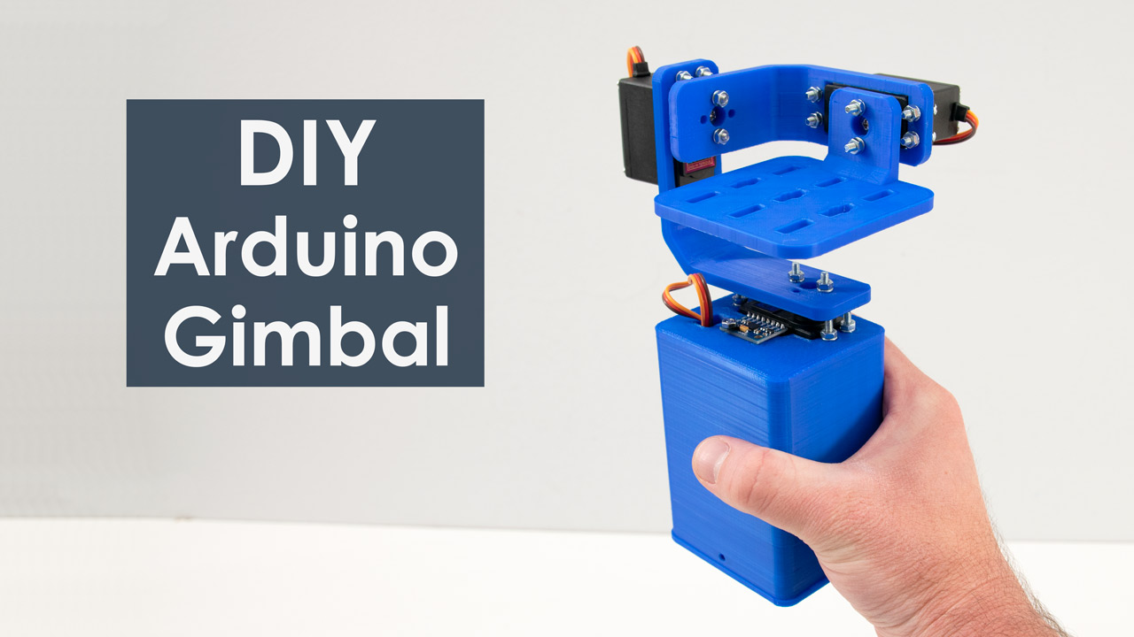
In the first example, using the Processing development environment, we will make a 3D visualization of the sensor orientation, and in the second example we will make a simple self-stabilizing platform or a DIY Gimbal. Based on the MPU6050 orientation and its fused accelerometer and gyroscope data, we control the three servos that keep the platform level.
How It Works
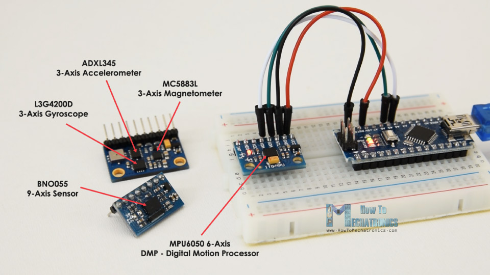
The MPU6050 IMU has both 3-Axis accelerometer and 3-Axis gyroscope integrated on a single chip.
The gyroscope measures rotational velocity or rate of change of the angular position over time, along the X, Y and Z axis. It uses MEMS technology and the Coriolis Effect for measuring, but for more details on it you can check my particular How MEMS Sensors Work tutorial. The outputs of the gyroscope are in degrees per second, so in order to get the angular position we just need to integrate the angular velocity.
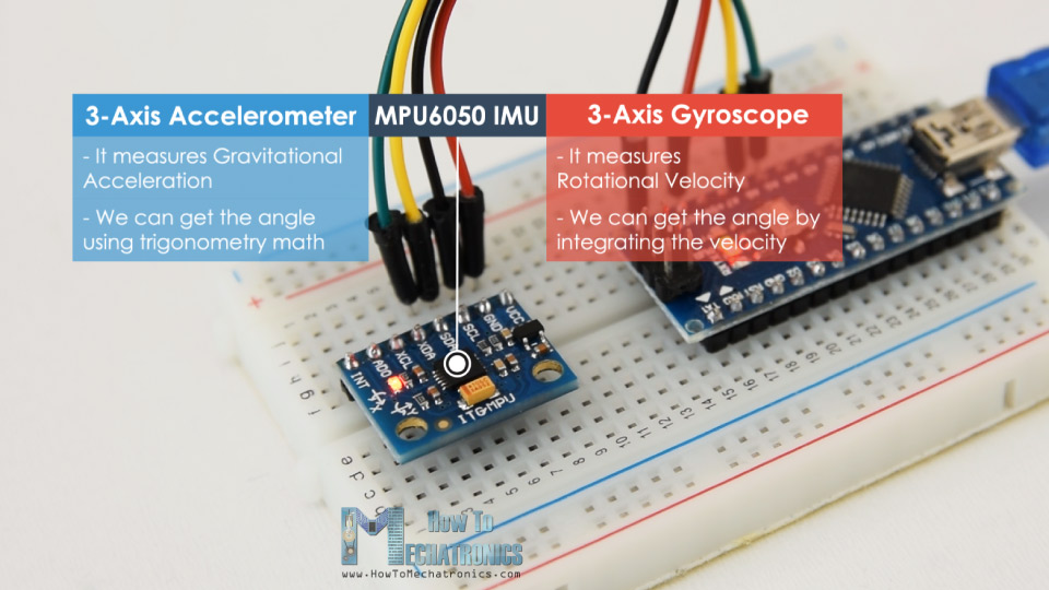
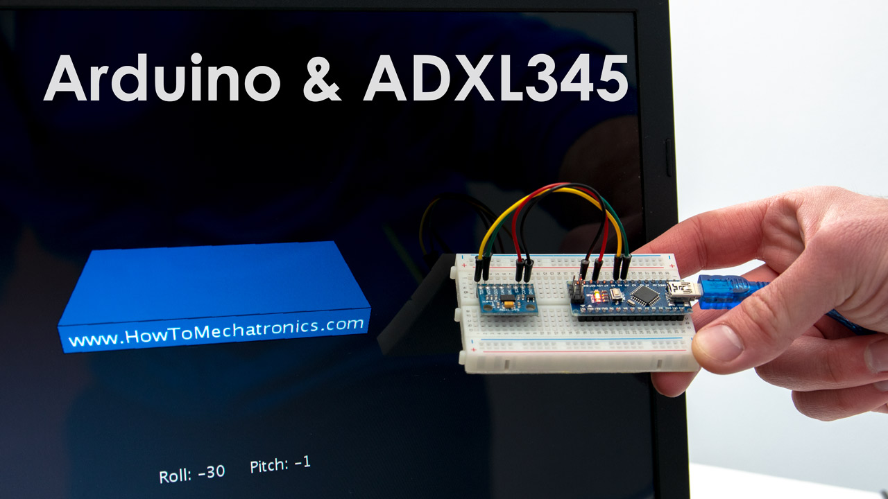
On the other hand, the MPU6050 accelerometer measures acceleration in the same way as explained in the previous video for the ADXL345 accelerometer sensor. Briefly, it can measure gravitational acceleration along the 3 axes and using some trigonometry math we can calculate the angle at which the sensor is positioned. So, if we fuse, or combine the accelerometer and gyroscope data we can get very accurate information about the sensor orientation.
The MPU6050 IMU is also called six-axis motion tracking device or 6 DoF (six Degrees of Freedom) device, because of its 6 outputs, or the 3 accelerometer outputs and the 3 gyroscope outputs.
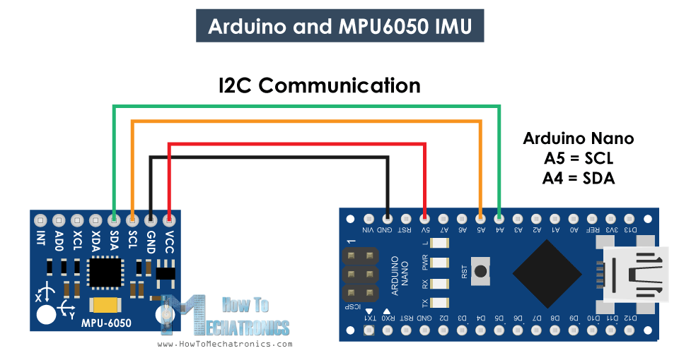
Arduino and MPU6050
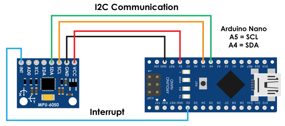
Let’s take a look how we can connect and read the data from the MPU6050 sensor using the Arduino. We are using the I2C protocol for communication with the Arduino so we need only two wires for connecting it, plus the two wires for powering.
You can get the components needed for this Arduino Tutorial from the links below:
- MPU6050 IMU …………………………..…. Amazon / Banggood / AliExpress
- Arduino Board ………………………….….. Amazon / Banggood / AliExpress
- Breadboard and Jump Wires ………… Amazon / Banggood / AliExpress
Disclosure: These are affiliate links. As an Amazon Associate I earn from qualifying purchases.
MPU6050 Arduino Code
Here’s the Arduino code for reading the data from the MPU6050 sensor. Below the code you can find a detail description of it.
/*
   Arduino and MPU6050 Accelerometer and Gyroscope Sensor Tutorial
   by Dejan, https://howtomechatronics.com
*/
#include <Wire.h>
const int MPU = 0x68; // MPU6050 I2C address
float AccX, AccY, AccZ;
float GyroX, GyroY, GyroZ;
float accAngleX, accAngleY, gyroAngleX, gyroAngleY, gyroAngleZ;
float roll, pitch, yaw;
float AccErrorX, AccErrorY, GyroErrorX, GyroErrorY, GyroErrorZ;
float elapsedTime, currentTime, previousTime;
int c = 0;
void setup() {
  Serial.begin(19200);
  Wire.begin();                      // Initialize comunication
  Wire.beginTransmission(MPU);       // Start communication with MPU6050 // MPU=0x68
  Wire.write(0x6B);                  // Talk to the register 6B
  Wire.write(0x00);                  // Make reset - place a 0 into the 6B register
  Wire.endTransmission(true);        //end the transmission
  /*
  // Configure Accelerometer Sensitivity - Full Scale Range (default +/- 2g)
  Wire.beginTransmission(MPU);
  Wire.write(0x1C);                  //Talk to the ACCEL_CONFIG register (1C hex)
  Wire.write(0x10);                  //Set the register bits as 00010000 (+/- 8g full scale range)
  Wire.endTransmission(true);
  // Configure Gyro Sensitivity - Full Scale Range (default +/- 250deg/s)
  Wire.beginTransmission(MPU);
  Wire.write(0x1B);                   // Talk to the GYRO_CONFIG register (1B hex)
  Wire.write(0x10);                   // Set the register bits as 00010000 (1000deg/s full scale)
  Wire.endTransmission(true);
  delay(20);
  */
  // Call this function if you need to get the IMU error values for your module
  calculate_IMU_error();
  delay(20);
}
void loop() {
  // === Read acceleromter data === //
  Wire.beginTransmission(MPU);
  Wire.write(0x3B); // Start with register 0x3B (ACCEL_XOUT_H)
  Wire.endTransmission(false);
  Wire.requestFrom(MPU, 6, true); // Read 6 registers total, each axis value is stored in 2 registers
  //For a range of +-2g, we need to divide the raw values by 16384, according to the datasheet
  AccX = (Wire.read() << 8 | Wire.read()) / 16384.0; // X-axis value
  AccY = (Wire.read() << 8 | Wire.read()) / 16384.0; // Y-axis value
  AccZ = (Wire.read() << 8 | Wire.read()) / 16384.0; // Z-axis value
  // Calculating Roll and Pitch from the accelerometer data
  accAngleX = (atan(AccY / sqrt(pow(AccX, 2) + pow(AccZ, 2))) * 180 / PI) - 0.58; // AccErrorX ~(0.58) See the calculate_IMU_error()custom function for more details
  accAngleY = (atan(-1 * AccX / sqrt(pow(AccY, 2) + pow(AccZ, 2))) * 180 / PI) + 1.58; // AccErrorY ~(-1.58)
  // === Read gyroscope data === //
  previousTime = currentTime;        // Previous time is stored before the actual time read
  currentTime = millis();            // Current time actual time read
  elapsedTime = (currentTime - previousTime) / 1000; // Divide by 1000 to get seconds
  Wire.beginTransmission(MPU);
  Wire.write(0x43); // Gyro data first register address 0x43
  Wire.endTransmission(false);
  Wire.requestFrom(MPU, 6, true); // Read 4 registers total, each axis value is stored in 2 registers
  GyroX = (Wire.read() << 8 | Wire.read()) / 131.0; // For a 250deg/s range we have to divide first the raw value by 131.0, according to the datasheet
  GyroY = (Wire.read() << 8 | Wire.read()) / 131.0;
  GyroZ = (Wire.read() << 8 | Wire.read()) / 131.0;
  // Correct the outputs with the calculated error values
  GyroX = GyroX + 0.56; // GyroErrorX ~(-0.56)
  GyroY = GyroY - 2; // GyroErrorY ~(2)
  GyroZ = GyroZ + 0.79; // GyroErrorZ ~ (-0.8)
  // Currently the raw values are in degrees per seconds, deg/s, so we need to multiply by sendonds (s) to get the angle in degrees
  gyroAngleX = gyroAngleX + GyroX * elapsedTime; // deg/s * s = deg
  gyroAngleY = gyroAngleY + GyroY * elapsedTime;
  yaw =  yaw + GyroZ * elapsedTime;
  // Complementary filter - combine acceleromter and gyro angle values
  roll = 0.96 * gyroAngleX + 0.04 * accAngleX;
  pitch = 0.96 * gyroAngleY + 0.04 * accAngleY;

  // Print the values on the serial monitor
  Serial.print(roll);
  Serial.print("/");
  Serial.print(pitch);
  Serial.print("/");
  Serial.println(yaw);
}
void calculate_IMU_error() {
  // We can call this funtion in the setup section to calculate the accelerometer and gyro data error. From here we will get the error values used in the above equations printed on the Serial Monitor.
  // Note that we should place the IMU flat in order to get the proper values, so that we then can the correct values
  // Read accelerometer values 200 times
  while (c < 200) {
    Wire.beginTransmission(MPU);
    Wire.write(0x3B);
    Wire.endTransmission(false);
    Wire.requestFrom(MPU, 6, true);
    AccX = (Wire.read() << 8 | Wire.read()) / 16384.0 ;
    AccY = (Wire.read() << 8 | Wire.read()) / 16384.0 ;
    AccZ = (Wire.read() << 8 | Wire.read()) / 16384.0 ;
    // Sum all readings
    AccErrorX = AccErrorX + ((atan((AccY) / sqrt(pow((AccX), 2) + pow((AccZ), 2))) * 180 / PI));
    AccErrorY = AccErrorY + ((atan(-1 * (AccX) / sqrt(pow((AccY), 2) + pow((AccZ), 2))) * 180 / PI));
    c++;
  }
  //Divide the sum by 200 to get the error value
  AccErrorX = AccErrorX / 200;
  AccErrorY = AccErrorY / 200;
  c = 0;
  // Read gyro values 200 times
  while (c < 200) {
    Wire.beginTransmission(MPU);
    Wire.write(0x43);
    Wire.endTransmission(false);
    Wire.requestFrom(MPU, 6, true);
    GyroX = Wire.read() << 8 | Wire.read();
    GyroY = Wire.read() << 8 | Wire.read();
    GyroZ = Wire.read() << 8 | Wire.read();
    // Sum all readings
    GyroErrorX = GyroErrorX + (GyroX / 131.0);
    GyroErrorY = GyroErrorY + (GyroY / 131.0);
    GyroErrorZ = GyroErrorZ + (GyroZ / 131.0);
    c++;
  }
  //Divide the sum by 200 to get the error value
  GyroErrorX = GyroErrorX / 200;
  GyroErrorY = GyroErrorY / 200;
  GyroErrorZ = GyroErrorZ / 200;
  // Print the error values on the Serial Monitor
  Serial.print("AccErrorX: ");
  Serial.println(AccErrorX);
  Serial.print("AccErrorY: ");
  Serial.println(AccErrorY);
  Serial.print("GyroErrorX: ");
  Serial.println(GyroErrorX);
  Serial.print("GyroErrorY: ");
  Serial.println(GyroErrorY);
  Serial.print("GyroErrorZ: ");
  Serial.println(GyroErrorZ);
}Code language: PHP (php)
Code Description: So first we need to include the Wire.h library which is used for the I2C communication and define some variables needed storing the data.
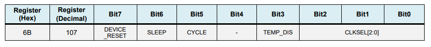
In the setup section, we need initialize the wire library and reset the sensor through the power management register. In order to do that we need to take a look at the datasheet of the sensor from where we can see the register address.
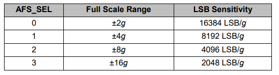
Also, if we want, we can select the Full-Scale Range for the accelerometer and the gyroscope using their configuration registers. For this example, we will use the default +- 2g range for the accelerometer and 250 degrees/s range for the gyroscope, so I will leave this part of the code commented.
// Configure Accelerometer Sensitivity - Full Scale Range (default +/- 2g)
  Wire.beginTransmission(MPU);
  Wire.write(0x1C);                  //Talk to the ACCEL_CONFIG register (1C hex)
  Wire.write(0x10);                  //Set the register bits as 00010000 (+/- 8g full scale range)
  Wire.endTransmission(true);
  // Configure Gyro Sensitivity - Full Scale Range (default +/- 250deg/s)
  Wire.beginTransmission(MPU);
  Wire.write(0x1B);                   // Talk to the GYRO_CONFIG register (1B hex)
  Wire.write(0x10);                   // Set the register bits as 00010000 (1000deg/s full scale)
  Wire.endTransmission(true);
  */Code language: JavaScript (javascript)
In the loop section we start by reading the accelerometer data. The data for each axis is stored in two bytes or registers and we can see the addresses of these registers from the datasheet of the sensor.
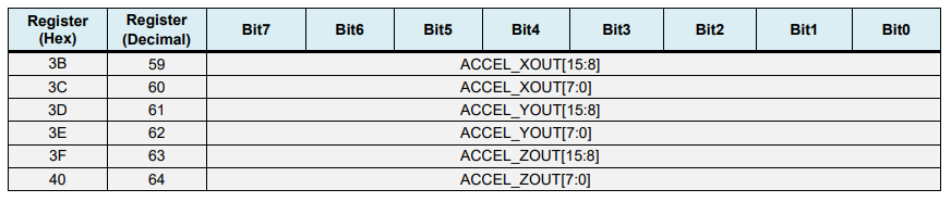
In order to read them all, we start with the first register, and using the requiestFrom() function we request to read all 6 registers for the X, Y and Z axes. Then we read the data from each register, and because the outputs are twos complement, we combine them appropriately to get the correct values.
// === Read acceleromter data === //
  Wire.beginTransmission(MPU);
  Wire.write(0x3B); // Start with register 0x3B (ACCEL_XOUT_H)
  Wire.endTransmission(false);
  Wire.requestFrom(MPU, 6, true); // Read 6 registers total, each axis value is stored in 2 registers
  //For a range of +-2g, we need to divide the raw values by 16384, according to the datasheet
  AccX = (Wire.read() << 8 | Wire.read()) / 16384.0; // X-axis value
  AccY = (Wire.read() << 8 | Wire.read()) / 16384.0; // Y-axis value
  AccZ = (Wire.read() << 8 | Wire.read()) / 16384.0; // Z-axis valueCode language: JavaScript (javascript)
In order to get output values from -1g to +1g, suitable for calculating the angles, we divide the output with the previously selected sensitivity.
Finally, using these two formulas, we calculate the roll and pitch angles from the accelerometer data.
// Calculating Roll and Pitch from the accelerometer data
  accAngleX = (atan(AccY / sqrt(pow(AccX, 2) + pow(AccZ, 2))) * 180 / PI) - 0.58; // AccErrorX ~(0.58) See the calculate_IMU_error()custom function for more details
  accAngleY = (atan(-1 * AccX / sqrt(pow(AccY, 2) + pow(AccZ, 2))) * 180 / PI) + 1.58; // AccErrorY ~(-1.58)Code language: JavaScript (javascript)
Next, using the same method we get the gyroscope data.
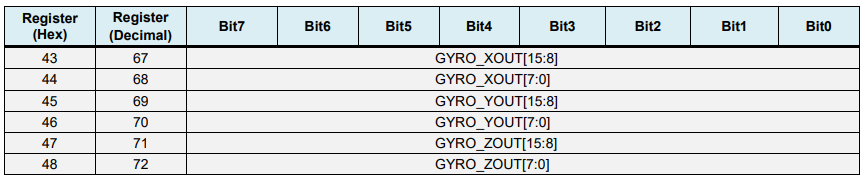
We read the six gyroscope registers, combine their data appropriately and divide it by the previously selected sensitivity in order to get the output in degrees per second.
// === Read gyroscope data === //
  previousTime = currentTime;        // Previous time is stored before the actual time read
  currentTime = millis();            // Current time actual time read
  elapsedTime = (currentTime - previousTime) / 1000; // Divide by 1000 to get seconds
  Wire.beginTransmission(MPU);
  Wire.write(0x43); // Gyro data first register address 0x43
  Wire.endTransmission(false);
  Wire.requestFrom(MPU, 6, true); // Read 4 registers total, each axis value is stored in 2 registers
  GyroX = (Wire.read() << 8 | Wire.read()) / 131.0; // For a 250deg/s range we have to divide first the raw value by 131.0, according to the datasheet
  GyroY = (Wire.read() << 8 | Wire.read()) / 131.0;
  GyroZ = (Wire.read() << 8 | Wire.read()) / 131.0;Code language: JavaScript (javascript)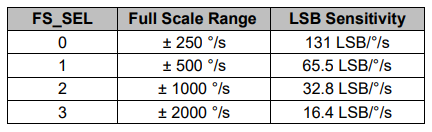
Here you can notice that I correct the output values with some small calculated error values, which I will explain how we get them in a minute. So as the outputs are in degrees per second, now we need to multiply them with the time to get just degrees. The time value is captured before each reading iteration using the millis() function.
// Correct the outputs with the calculated error values
  GyroX = GyroX + 0.56; // GyroErrorX ~(-0.56)
  GyroY = GyroY - 2; // GyroErrorY ~(2)
  GyroZ = GyroZ + 0.79; // GyroErrorZ ~ (-0.8)
  // Currently the raw values are in degrees per seconds, deg/s, so we need to multiply by sendonds (s) to get the angle in degrees
  gyroAngleX = gyroAngleX + GyroX * elapsedTime; // deg/s * s = deg
  gyroAngleY = gyroAngleY + GyroY * elapsedTime;
  yaw =  yaw + GyroZ * elapsedTime;Code language: JavaScript (javascript)
Finally, we fuse the accelerometer and the gyroscope data using a complementary filter. Here, we take 96% of the gyroscope data because it is very accurate and doesn’t suffer from external forces. The down side of the gyroscope is that it drifts, or it introduces error in the output as the time goes on. Therefore, on the long term, we use the data from the accelerometer, 4% in this case, enough to eliminate the gyroscope drift error.
// Complementary filter - combine acceleromter and gyro angle values
  roll = 0.96 * gyroAngleX + 0.04 * accAngleX;
  pitch = 0.96 * gyroAngleY + 0.04 * accAngleY;Code language: JavaScript (javascript)
However, as we cannot calculate the Yaw from the accelerometer data, we cannot implement the complementary filter on it.
Before we take a look at the results, let me quickly explain how to get the error correction values. For calculate these errors we can call the calculate_IMU_error() custom function while the sensor is in flat still position. Here we do 200 readings for all outputs, we sum them and divide them by 200. As we are holding the sensor in flat still position, the expected output values should be 0. So, with this calculation we can get the average error the sensor makes.
void calculate_IMU_error() {
  // We can call this funtion in the setup section to calculate the accelerometer and gyro data error. From here we will get the error values used in the above equations printed on the Serial Monitor.
  // Note that we should place the IMU flat in order to get the proper values, so that we then can the correct values
  // Read accelerometer values 200 times
  while (c < 200) {
    Wire.beginTransmission(MPU);
    Wire.write(0x3B);
    Wire.endTransmission(false);
    Wire.requestFrom(MPU, 6, true);
    AccX = (Wire.read() << 8 | Wire.read()) / 16384.0 ;
    AccY = (Wire.read() << 8 | Wire.read()) / 16384.0 ;
    AccZ = (Wire.read() << 8 | Wire.read()) / 16384.0 ;
    // Sum all readings
    AccErrorX = AccErrorX + ((atan((AccY) / sqrt(pow((AccX), 2) + pow((AccZ), 2))) * 180 / PI));
    AccErrorY = AccErrorY + ((atan(-1 * (AccX) / sqrt(pow((AccY), 2) + pow((AccZ), 2))) * 180 / PI));
    c++;
  }
  //Divide the sum by 200 to get the error value
  AccErrorX = AccErrorX / 200;
  AccErrorY = AccErrorY / 200;
  c = 0;
  // Read gyro values 200 times
  while (c < 200) {
    Wire.beginTransmission(MPU);
    Wire.write(0x43);
    Wire.endTransmission(false);
    Wire.requestFrom(MPU, 6, true);
    GyroX = Wire.read() << 8 | Wire.read();
    GyroY = Wire.read() << 8 | Wire.read();
    GyroZ = Wire.read() << 8 | Wire.read();
    // Sum all readings
    GyroErrorX = GyroErrorX + (GyroX / 131.0);
    GyroErrorY = GyroErrorY + (GyroY / 131.0);
    GyroErrorZ = GyroErrorZ + (GyroZ / 131.0);
    c++;
  }
  //Divide the sum by 200 to get the error value
  GyroErrorX = GyroErrorX / 200;
  GyroErrorY = GyroErrorY / 200;
  GyroErrorZ = GyroErrorZ / 200;
  // Print the error values on the Serial Monitor
  Serial.print("AccErrorX: ");
  Serial.println(AccErrorX);
  Serial.print("AccErrorY: ");
  Serial.println(AccErrorY);
  Serial.print("GyroErrorX: ");
  Serial.println(GyroErrorX);
  Serial.print("GyroErrorY: ");
  Serial.println(GyroErrorY);
  Serial.print("GyroErrorZ: ");
  Serial.println(GyroErrorZ);
}Code language: PHP (php)
We simply print the values on the serial monitor and once we know them, we can implement them in the code as shown earlier, for both the roll and pitch calculation, as well as for the 3 gyroscope outputs.
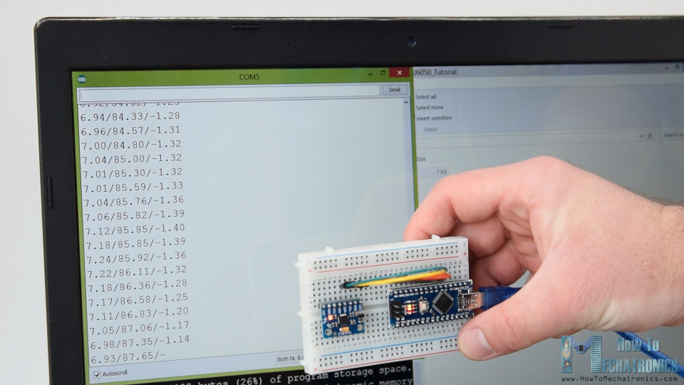
Finally, using the Serial.print function we can print the Roll, Pitch and Yaw values on the serial monitor and see whether the sensor works properly.
MPU6050 Orientation Tracking – 3D Visualization
Next, in order to make the 3D visualization example we just need accept this data the Arduino is sending through the serial port in the Processing development environment. Here’s the complete Processing code:
/*
Arduino and MPU6050 IMU - 3D Visualization Example
by Dejan, https://howtomechatronics.com
*/
import processing.serial.*;
import java.awt.event.KeyEvent;
import java.io.IOException;
Serial myPort;
String data="";
float roll, pitch,yaw;
void setup() {
size (2560, 1440, P3D);
myPort = new Serial(this, "COM7", 19200); // starts the serial communication
myPort.bufferUntil('\n');
}
void draw() {
translate(width/2, height/2, 0);
background(233);
textSize(22);
text("Roll: " + int(roll) + " Pitch: " + int(pitch), -100, 265);
// Rotate the object
rotateX(radians(-pitch));
rotateZ(radians(roll));
rotateY(radians(yaw));
// 3D 0bject
textSize(30);
fill(0, 76, 153);
box (386, 40, 200); // Draw box
textSize(25);
fill(255, 255, 255);
text("www.HowToMechatronics.com", -183, 10, 101);
//delay(10);
//println("ypr:\t" + angleX + "\t" + angleY); // Print the values to check whether we are getting proper values
}
// Read data from the Serial Port
void serialEvent (Serial myPort) {
// reads the data from the Serial Port up to the character '.' and puts it into the String variable "data".
data = myPort.readStringUntil('\n');
// if you got any bytes other than the linefeed:
if (data != null) {
data = trim(data);
// split the string at "/"
String items[] = split(data, '/');
if (items.length > 1) {
//--- Roll,Pitch in degrees
roll = float(items[0]);
pitch = float(items[1]);
yaw = float(items[2]);
}
}
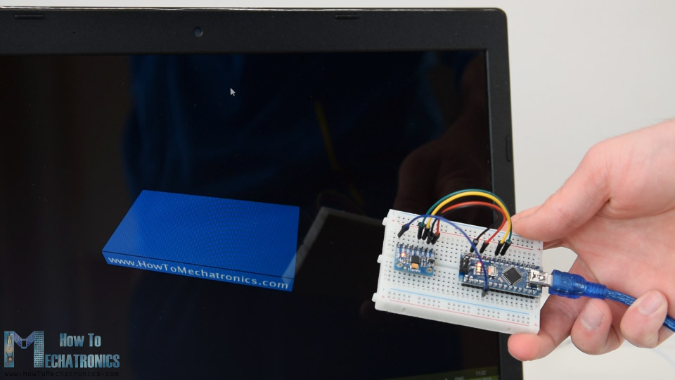
}Code language: JavaScript (javascript)Here we read the incoming data from the Arduino and put it into the appropriate Roll, Pitch and Yaw variables. In the main draw loop, we use these values to rotate the 3D object, in this case that’s a simple box with a particular color and text on it.
If we run the sketch, we can see how good the MPU6050 sensor is for tracking orientation. The 3D object tracks the orientation of the sensor quite accurate and it’s also very responsive.
As I mentioned, the only down side is that the Yaw will drift over time because we cannot use the complementary filter for it. For improving this we need to use an additional sensor. That’s usually a magnetometer which can be used as a long-term correction for the gyroscope Yaw drift. However, the MPU6050 actually have a feature that’s called Digital Motion Processor which is used for onboard calculations of the data and it’s capable of eliminating the Yaw drift.
Here’s the same 3D example with the Digital Motion Processor in use. We can see how accurate the orientation tracking is now, without the Yaw drift. The onboard processor can also calculate and output Quaternions which are used for representing orientations and rotations of objects in three dimensions. In this example we are actually using quaternions for representing the orientation which also doesn’t suffer from Gimbal lock which occurs when using Euler angles.
Nevertheless, getting this data from the sensor is a bit more complicated than what we explained earlier. First of all, we need to connect and additional wire to an Arduino digital pin. That’s an interrupt pin which is used for reading this data type from the MPU6050.
The code is also a bit more complicated so that’s why we are going to use the i2cdevlib library by Jeff Rowberg. This library can be downloaded from GitHub and I will include a link to in on the website article.
Once we install the library, we can open the MPU6050_DMP6 example from the library. This example is well explained with comments for each line.
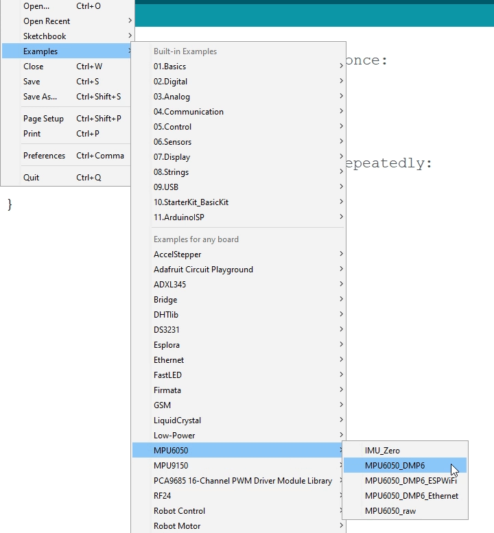
Here we can select what kind of output we want, quaternions, Euler angles, yaw, pitch and roll, accelerations value or quaternions for the 3D visualization. This library also includes a Processing sketch for the 3D visualization example. I just modified it to get the box shape as in the previous example. Here’s the 3D visualization Processing code that works with the MPU6050_DPM6 example, for selected “OUTPUT_TEAPOT” output:
/*
    Arduino and MPU6050 IMU - 3D Visualization Example
     by Dejan, https://howtomechatronics.com
*/
import processing.serial.*;
import java.awt.event.KeyEvent;
import java.io.IOException;
Serial myPort;
String data="";
float roll, pitch,yaw;
void setup() {
  size (2560, 1440, P3D);
  myPort = new Serial(this, "COM7", 19200); // starts the serial communication
  myPort.bufferUntil('\n');
}
void draw() {
  translate(width/2, height/2, 0);
  background(233);
  textSize(22);
  text("Roll: " + int(roll) + "     Pitch: " + int(pitch), -100, 265);
  // Rotate the object
  rotateX(radians(-pitch));
  rotateZ(radians(roll));
  rotateY(radians(yaw));

  // 3D 0bject
  textSize(30);
  fill(0, 76, 153);
  box (386, 40, 200); // Draw box
  textSize(25);
  fill(255, 255, 255);
  text("www.HowToMechatronics.com", -183, 10, 101);
  //delay(10);
  //println("ypr:\t" + angleX + "\t" + angleY); // Print the values to check whether we are getting proper values
}
// Read data from the Serial Port
void serialEvent (Serial myPort) {
  // reads the data from the Serial Port up to the character '.' and puts it into the String variable "data".
  data = myPort.readStringUntil('\n');
  // if you got any bytes other than the linefeed:
  if (data != null) {
    data = trim(data);
    // split the string at "/"
    String items[] = split(data, '/');
    if (items.length > 1) {
      //--- Roll,Pitch in degrees
      roll = float(items[0]);
      pitch = float(items[1]);
      yaw = float(items[2]);
    }
  }
}Code language: JavaScript (javascript)
So here using the serialEvent() function we receive the quaternions coming from the Arduino, and in the main draw loop we use them to rotate the 3D object. If we run the sketch, we can see how good quaternions are for rotating objects in three dimensions.
In order not to overload this tutorial, I placed the second example, the DIY Arduino Gimbal or Self-Stabilizing platform, on a separate article.
Feel free to ask any question related to this tutorial in the comments section below and also don’t forget to check my collection of Arduino Projects.
Hi, Thanks for this GREAT tutorial! It really helped me a lot to get rid of mpu libs, that I did not understand – I always prefer code, that I understand 😉
However, I think there is a mistake in your first sketch:
// Complementary filter – combine acceleromter and gyro angle values
roll = 0.96 * gyroAngleX + 0.04 * accAngleX;
pitch = 0.96 * gyroAngleY + 0.04 * accAngleY;
This is basiclaly correct – however, it seems to me, that you dont “close the loop”.. roll and pitch will continue to count up and up (or down), depending on the drift. We somehow have to “reset” the angles “a bit” each loop. My suggestion therefore is to write instead:
gyroAngleX = 0.96 * gyroAngleX + 0.04 * accAngleX;
gyroAngleY = 0.96 * gyroAngleY + 0.04 * accAngleY;
roll = gyroAngleX;
pitch = gyroAngleY;
With this change, the accAngle can “pull the vector back” to its correct place over time. Short term changes are mainly supported by gyroAngle.
What do you think about this?
you are correct.
Just the opposite. It should be –
gyroAngleX = roll;
gyroAngleY = pitch;
Also, include a delay at the end of the loop for Processing to work correctly like
delay(100);
Dude!!! I just want to say thank you. You did some really impressive work here. I cannot thank you enough. I needed this for my project and just giving such a detailed explanation on the gyroscope, how it works and how the data can be used exactly is beyond impressive. I’ve subscribed to your youtube channel now, you definitely gained a fan. Once again thanks for this really good work and keep it up.
Hey, so glad to hear this. Thanks! Cheers!
i ues the example of MPU6050 DMP6 and the last processing code,but it alway generate the Yaw will drift over time.
Yes, Hence to overcome the Yaw drift will need to either include a magnetometer in your code, or a new IMU module or implement a Kalman filter to reduce the overall drift.
Hi Dejan,
thanks for your impressive work on this project, it looks really amazing!
I tried to implement your code, but I got a problem that I don’t understand.
I did the wireing according to your description, I tried it on my Arduino Nano and Mega. I even used two different breakout boards for the MPU-6050, the GY-521 and the GY-87.
In all instances, when I look at my serial monitor, the three values just continue to count up, and they don’t represent my sensor angles at all. Here’s a short example:
5.83/-24.94/10.72
5.84/-24.96/10.73
5.84/-24.97/10.74
5.85/-24.99/10.74
5.85/-25.01/10.75
5.86/-25.03/10.76
5.86/-25.05/10.77
5.87/-25.07/10.77
do you have any idea what might be the problem?
Thank you very much!
Hey, thanks! Try to change the adjust the calculated error values, maybe that could help. The drift happens because of the gyroscope, so you could also try to use just the accelerometer to see whether it’s working properly.
I had the same problem. I ran the calculate_IMU_error function and substituted the new error values into the code and the values remained stable.
FYI – the error values that I obtained when running the calculate_IMU_error function are as follows:
AccErrorX ~(-1.80)
AccErrorY ~(4.40)
GyroErrorX ~(-2.18)
GyroErrorY ~(1.11)
GyroErrorZ ~ (0.75)
You perform:
gyroAngleX = gyroAngleX + GyroX * elapsedTime;
So each loop the old value of gyroAngleX is used to compute the new one. This may explain why XY and Z are changing even if you dont’ move the sensor.
If you just perform
gyroAngleX = GyroX * elapsedTime;
You’ll see the movement then the stabilisation. Maybe it would be better?
Hi Dejan
What a great project 👍👍👍
May I ask what 3d modeling software did you use?
Thank you! I used Solidworks for making the 3D Model.
Hi Dejan,
The table with LSB multiplier values for the accelerometer is incorrect and will provide pitch and roll values 1/2 the actual values. The corrected table is shown below:
* AFS_SEL | Full Scale Range | LSB Sensitivity
* ——–+——————+—————-
* 0 | +/- 2g | 8192 LSB/mg
* 1 | +/- 4g | 4096 LSB/mg
* 2 | +/- 8g | 2048 LSB/mg
* 3 | +/- 16g | 1024 LSB/mg
as shown in the new release (February 2019) of the MPU6050 library.
Thanks for delivering a really good tutorial on how to use this breakout board.
Ed
Hey, thanks for the input!