In this Arduino touch screen tutorial we will learn how to use TFT LCD Touch Screen with Arduino. You can watch the following video or read the written tutorial below.
Overview
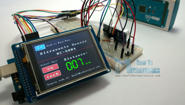
For this tutorial I composed three examples. The first example is distance measurement using ultrasonic sensor. The output from the sensor, or the distance is printed on the screen and using the touch screen we can select the units, either centimeters or inches.
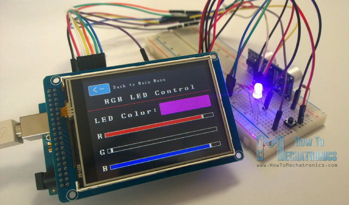
The next example is controlling an RGB LED using these three RGB sliders. For example if we start to slide the blue slider, the LED will light up in blue and increase the light as we would go to the maximum value. So the sliders can move from 0 to 255 and with their combination we can set any color to the RGB LED, but just keep in mind that the LED cannot represent the colors that much accurate.
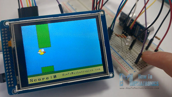
The third example is a game. Actually it’s a replica of the popular Flappy Bird game for smartphones. We can play the game using the push button or even using the touch screen itself.
Now we will go through each of these examples and step by step explain the codes behind them.
Parts needed for this Arduino Touch Screen
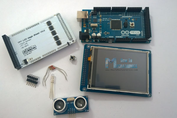
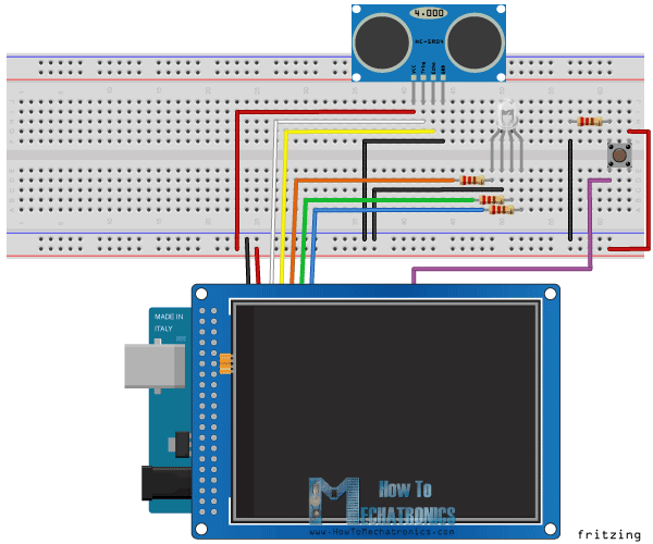
As an example I am using a 3.2” TFT Touch Screen in a combination with a TFT LCD Arduino Mega Shield. We need a shield because the TFT Touch screen works at 3.3V and the Arduino Mega outputs are 5 V. For the first example I have the HC-SR04 ultrasonic sensor, then for the second example an RGB LED with three resistors and a push button for the game example. Also I had to make a custom made pin header like this, by soldering pin headers and bend on of them so I could insert them in between the Arduino Board and the TFT Shield.
You can get these components from any of the sites below:
- 3.2″ TFT Touch Display……………….. Amazon / Banggood / AliExpress
- TFT Display Mega Shield……………… Amazon / Banggood / AliExpress
- Arduino Board …………………………… Amazon / Banggood / AliExpress
- Ultrasonic Module HC-SR04……….. Amazon / Banggood / AliExpress
Disclosure: These are affiliate links. As an Amazon Associate I earn from qualifying purchases.
Here’s the circuit schematic. We will use the GND pin, the digital pins from 8 to 13, as well as the pin number 14. As the 5V pins are already used by the TFT Screen I will use the pin number 13 as VCC, by setting it right away high in the setup section of code.
Arduino Touch Screen Code
As the code is a bit longer and for better understanding I will post the source code of the program in sections with description for each section. And at the end of this article I will post the complete source code.
I will use the UTFT and URTouch libraries made by Henning Karlsen. Here I would like to say thanks to him for the incredible work he has done. The libraries enable really easy use of the TFT Screens, and they work with many different TFT screens sizes, shields and controllers. You can download these libraries from his website, RinkyDinkElectronics.com and also find a lot of demo examples and detailed documentation of how to use them.
After we include the libraries we need to create UTFT and URTouch objects. The parameters of these objects depends on the model of the TFT Screen and Shield and these details can be also found in the documentation of the libraries.
Next we need to define the fonts that are coming with the libraries and also define some variables needed for the program. In the setup section we need to initiate the screen and the touch, define the pin modes for the connected sensor, the led and the button, and initially call the drawHomeSreen() custom function, which will draw the home screen of the program.
#include <UTFT.h>
#include <URTouch.h>

//==== Creating Objects
UTFT    myGLCD(SSD1289,38,39,40,41); //Parameters should be adjusted to your Display/Schield model
URTouch  myTouch( 6, 5, 4, 3, 2);

//==== Defining Variables
extern uint8_t SmallFont[];
extern uint8_t BigFont[];
extern uint8_t SevenSegNumFont[];

extern unsigned int bird01[0x41A];

int x, y;

char currentPage, selectedUnit;

//Ultrasonic Sensor
const int VCC = 13;
const int trigPin = 11;
const int echoPin = 12;

long duration;
int distanceInch, distanceCm;

// RGB LEDs
const int redLed = 10;
const int greenLed = 9;
const int blueLed = 8;
int xR=38;
int xG=38;
int xB=38;

// Floppy Bird
int xP = 319;
int yP = 100;
int yB = 30;
int fallRateInt = 0;
float fallRate =0;
int score=0;
const int button = 14;
int buttonState = 0;

void setup() {
// Initial setup
  myGLCD.InitLCD();
  myGLCD.clrScr();
  myTouch.InitTouch();
  myTouch.setPrecision(PREC_MEDIUM);

  // Defining Pin Modes
  pinMode(VCC, OUTPUT); // VCC
  pinMode(trigPin, OUTPUT); // Sets the trigPin as an Output
  pinMode(echoPin, INPUT); // Sets the echoPin as an Input
  pinMode(redLed, OUTPUT);
  pinMode(greenLed, OUTPUT);
  pinMode(blueLed, OUTPUT);
  pinMode(button, INPUT);
  digitalWrite(VCC, HIGH); // +5V - Pin 13 as VCC

  drawHomeScreen();  // Draws the Home Screen
  currentPage = '0'; // Indicates that we are at Home Screen
  selectedUnit = '0'; // Indicates the selected unit for the first example, cms or inches
}Code language: PHP (php)
So now I will explain how we can make the home screen of the program. With the setBackColor() function we need to set the background color of the text, black one in our case. Then we need to set the color to white, set the big font and using the print() function, we will print the string “Arduino TFT Tutorial” at the center of the screen and 10 pixels down the Y – Axis of the screen. Next we will set the color to red and draw the red line below the text. After that we need to set the color back to white, and print the two other strings, “by HowToMechatronics.com” using the small font and “Select Example” using the big font.
Next is the distance sensor button. First we need to set the color and then using the fillRoundRect() function we will draw the rounded rectangle. Then we will set the color back to white and using the drawRoundRect() function we will draw another rounded rectangle on top of the previous one, but this one will be without a fill so the overall appearance of the button looks like it has a frame. On top of the button we will print the text using the big font and the same background color as the fill of the button. The same procedure goes for the two other buttons.
// drawHomeScreen - Custom Function
void drawHomeScreen() {
  // Title
  myGLCD.setBackColor(0,0,0); // Sets the background color of the area where the text will be printed to black
  myGLCD.setColor(255, 255, 255); // Sets color to white
  myGLCD.setFont(BigFont); // Sets font to big
  myGLCD.print("Arduino TFT Tutorial", CENTER, 10); // Prints the string on the screen
  myGLCD.setColor(255, 0, 0); // Sets color to red
  myGLCD.drawLine(0,32,319,32); // Draws the red line
  myGLCD.setColor(255, 255, 255); // Sets color to white
  myGLCD.setFont(SmallFont); // Sets the font to small
  myGLCD.print("by HowToMechatronics.com", CENTER, 41); // Prints the string
  myGLCD.setFont(BigFont);
  myGLCD.print("Select Example", CENTER, 64);

  // Button - Distance Sensor
  myGLCD.setColor(16, 167, 103); // Sets green color
  myGLCD.fillRoundRect (35, 90, 285, 130); // Draws filled rounded rectangle
  myGLCD.setColor(255, 255, 255); // Sets color to white
  myGLCD.drawRoundRect (35, 90, 285, 130); // Draws rounded rectangle without a fill, so the overall appearance of the button looks like it has a frame
  myGLCD.setFont(BigFont); // Sets the font to big
  myGLCD.setBackColor(16, 167, 103); // Sets the background color of the area where the text will be printed to green, same as the button
  myGLCD.print("DISTANCE SENSOR", CENTER, 102); // Prints the string

  // Button - RGB LED Control
  myGLCD.setColor(16, 167, 103);
  myGLCD.fillRoundRect (35, 140, 285, 180);
  myGLCD.setColor(255, 255, 255);
  myGLCD.drawRoundRect (35, 140, 285, 180);
  myGLCD.setFont(BigFont);
  myGLCD.setBackColor(16, 167, 103);
  myGLCD.print("RGB LED CONTROL", CENTER, 152);

  // Button - Birduino
  myGLCD.setColor(16, 167, 103);
  myGLCD.fillRoundRect (35, 190, 285, 230);
  myGLCD.setColor(255, 255, 255);
  myGLCD.drawRoundRect (35, 190, 285, 230);
  myGLCD.setFont(BigFont);
  myGLCD.setBackColor(16, 167, 103);
  myGLCD.print("BIRDUINO GAME", CENTER, 202);
}Code language: PHP (php)
Now we need to make the buttons functional so that when we press them they would send us to the appropriate example. In the setup section we set the character ‘0’ to the currentPage variable, which will indicate that we are at the home screen. So if that’s true, and if we press on the screen this if statement would become true and using these lines here we will get the X and Y coordinates where the screen has been pressed. If that’s the area that covers the first button we will call the drawDistanceSensor() custom function which will activate the distance sensor example. Also we will set the character ‘1’ to the variable currentPage which will indicate that we are at the first example. The drawFrame() custom function is used for highlighting the button when it’s pressed. The same procedure goes for the two other buttons.
//========== The loop section ========
void loop() {
  // Home Screen
  if (currentPage == '0') {
    if (myTouch.dataAvailable()) {
      myTouch.read();
      x=myTouch.getX(); // X coordinate where the screen has been pressed
      y=myTouch.getY(); // Y coordinates where the screen has been pressed
      // If we press the Distance Sensor Button
      if ((x>=35) && (x<=285) && (y>=90) && (y<=130)) {
        drawFrame(35, 90, 285, 130); // Custom Function -Highlighs the buttons when it's pressed
        currentPage = '1'; // Indicates that we are the first example
        myGLCD.clrScr(); // Clears the screen
        drawDistanceSensor(); // It is called only once, because in the next iteration of the loop, this above if statement will be false so this funtion won't be called. This function will draw the graphics of the first example.
      }
      // If we press the RGB LED Control Button
      if ((x>=35) && (x<=285) && (y>=140) && (y<=180)) {
        drawFrame(35, 140, 285, 180);
        currentPage = '2';
        myGLCD.clrScr();
        drawLedControl();
      }
      // If we press the Birduino Game Button
      if ((x>=35) && (x<=285) && (y>=190) && (y<=230)) {
        drawFrame(35, 190, 285, 230);
        currentPage = '3';
        myGLCD.clrScr();
        myGLCD.setColor(114, 198, 206);
        myGLCD.fillRect(0,0,319,239);
        drawGround();
        drawPilars(xP,yP);
        drawBird(30);
        delay(1000);
      }
    }
  }
  // Distance Sensor Example
  if (currentPage == '1') {
      getDistance(); // Gets distance from the sensor and this function is repeatedly called while we are at the first example in order to print the lasest results from the distance sensor
      if (myTouch.dataAvailable()) {
        myTouch.read();
        x=myTouch.getX();
        y=myTouch.getY();

        // If we press the Centimeters Button
        if ((x>=10) && (x<=135) &&(y>=90) && (y<=163)) {
          selectedUnit = '0';
        }
        // If we press the Inches Button
        if ((x>=10) && (x<=135) &&(y>=173) && (y<=201)) {
          selectedUnit = '1';
        }
        // If we press the Back Button
        if ((x>=10) && (x<=60) &&(y>=10) && (y<=36)) {
          drawFrame(10, 10, 60, 36);
          currentPage = '0'; // Indicates we are at home screen
          myGLCD.clrScr();
          drawHomeScreen(); // Draws the home screen
        }
      }
  }

  // RGB LED Control
  if (currentPage == '2') {
    setLedColor();
    if (myTouch.dataAvailable()) {
        myTouch.read();
        x=myTouch.getX();
        y=myTouch.getY();

        //Back button
        if ((x>=10) && (x<=60) &&(y>=10) && (y<=36)) {
          drawFrame(10, 10, 60, 36);
          currentPage = '0';
          myGLCD.clrScr();
          drawHomeScreen();
          // Turns the LED off
          analogWrite(redLed, 0);
          analogWrite(greenLed, 0);
          analogWrite(blueLed, 0);
        }
    }
  }
//==== This section of the code, for the game example, is explained in my next tutorial
  // Birduino Game
  if (currentPage == '3') {
    //delay(1);
    xP=xP-3;
    drawPilars(xP, yP);

    yB+=fallRateInt;
    fallRate=fallRate+0.4;
    fallRateInt= int(fallRate);
    if (yB>=220) {
      yB=220;
    }
    if(yB>=180 || yB<=0){
      restartGame();
    }
    if((xP<=85) && (xP>=30) && (yB<=yP-2)){
      restartGame();
    }
    if((xP<=85) && (xP>=30) && (yB>=yP+60)){
      restartGame();
    }
    drawBird(yB);

    if (xP<=-51){
      xP=319;
      yP = rand() % 100+20;
      score++;
    }
    if (myTouch.dataAvailable()) {
        myTouch.read();
        x=myTouch.getX();
        y=myTouch.getY();
        if ((x>=0) && (x<=319) &&(y>=50) && (y<=239)) {
          fallRate=-5;
        }
    }
    buttonState = digitalRead(button);
    if (buttonState == HIGH) {
      fallRate=-5;
      }
  }
    if (myTouch.dataAvailable()) {
        myTouch.read();
        x=myTouch.getX();
        y=myTouch.getY();
        if ((x>=10) && (x<=60) &&(y>=10) && (y<=36)) {
          drawFrame(10, 10, 60, 36);
          currentPage = '0';
          myGLCD.clrScr();
          drawHomeScreen();
          analogWrite(redLed, 0);
          analogWrite(greenLed, 0);
          analogWrite(blueLed, 0);
        }
    }
}Code language: JavaScript (javascript)
So the drawDistanceSensor() custom function needs to be called only once when the button is pressed in order to draw all the graphics of this example in similar way as we described for the home screen. However, the getDistance() custom function needs to be called repeatedly in order to print the latest results of the distance measured by the sensor.
Here’s that function which uses the ultrasonic sensor to calculate the distance and print the values with SevenSegNum font in green color, either in centimeters or inches. If you need more details how the ultrasonic sensor works you can check my particular tutorial for that. Back in the loop section we can see what happens when we press the select unit buttons as well as the back button.
//===== getDistance() - Custom Function
void getDistance() {
  // Clears the trigPin
  digitalWrite(trigPin, LOW);
  delayMicroseconds(2);
  // Sets the trigPin on HIGH state for 10 micro seconds
  digitalWrite(trigPin, HIGH);
  delayMicroseconds(10);
  digitalWrite(trigPin, LOW);
  // Reads the echoPin, returns the sound wave travel time in microseconds
  duration = pulseIn(echoPin, HIGH);
  // Calculating the distance
  distanceCm= duration*0.034/2;
  distanceInch= distanceCm/2.53;
  // Prints the distance in centimeters
  if (selectedUnit == '0' && distanceCm <=400) {
    myGLCD.setFont(SevenSegNumFont);
    myGLCD.setColor(0, 255, 0);
    myGLCD.setBackColor(0, 0, 0);
    myGLCD.printNumI(distanceCm,130, 145, 3,'0');
    myGLCD.setFont(BigFont);
    myGLCD.print("cm  ", 235, 178);

  }
  // Prints the distance in inches
  if (selectedUnit == '1' && distanceCm <=160) {
    myGLCD.setFont(SevenSegNumFont);
    myGLCD.setColor(0, 255, 0);
    myGLCD.setBackColor(0, 0, 0);
    myGLCD.printNumI(distanceInch,130, 145, 3,'0');
    myGLCD.setFont(BigFont);
    myGLCD.print("inch", 235, 178);
  }
  delay(10);
}Code language: PHP (php)
Ok next is the RGB LED Control example. If we press the second button, the drawLedControl() custom function will be called only once for drawing the graphic of that example and the setLedColor() custom function will be repeatedly called. In this function we use the touch screen to set the values of the 3 sliders from 0 to 255. With the if statements we confine the area of each slider and get the X value of the slider. So the values of the X coordinate of each slider are from 38 to 310 pixels and we need to map these values into values from 0 to 255 which will be used as a PWM signal for lighting up the LED. If you need more details how the RGB LED works you can check my particular tutorial for that. The rest of the code in this custom function is for drawing the sliders. Back in the loop section we only have the back button which also turns off the LED when pressed.
//============= setLedColor() - Custom Funtion
void setLedColor() {
  if (myTouch.dataAvailable()) {
    myTouch.read();
    x=myTouch.getX();
    y=myTouch.getY();
    // Area of the Red color slider
    if( (y>=130) && (y<=156)) {
      xR=x; // Stores the X value where the screen has been pressed in to variable xR
      if (xR<=38) { // Confines the area of the slider to be above 38 pixels
        xR=38;
      }
      if (xR>=303){ /// Confines the area of the slider to be under 310 pixels
        xR=303;
      }
    }
    // Area of the Green color slider
    if( (y>=170) && (y<=196)) {
      xG=x;
      if (xG<=38) {
        xG=38;
      }
      if (xG>=303){
        xG=303;
      }
    }
    // Area of the Blue color slider
    if( (y>=210) && (y<=236)) {
      xB=x;
      if (xB<=38) {
        xB=38;
      }
      if (xB>=303){
        xB=303;
      }
    }
  }
  // Maps the values of the X - Axis from 38 to 0 and 310 to 255, because we need values from 0 to 255 for turning on the led
  int xRC = map(xR,38,310,0,255);
  int xGC = map(xG,38,310,0,255);
  int xBC = map(xB,38,310,0,255);

  // Sends PWM signal to the pins of the led
  analogWrite(redLed, xRC);
  analogWrite(greenLed, xGC);
  analogWrite(blueLed, xBC);

  // Draws a rectangle with the latest color combination
  myGLCD.setColor(xRC, xGC, xBC);
  myGLCD.fillRoundRect(175, 87, 310, 119);

  // Draws the positioners
  myGLCD.setColor(255, 255, 255);
  myGLCD.fillRect(xR,139,(xR+4),147); // Positioner
  myGLCD.setColor(xRC, 0, 0);
  myGLCD.fillRect(31, 139, (xR-1), 147);
  myGLCD.setColor(0, 0, 0);
  myGLCD.fillRect((xR+5), 139, 309, 147);

  myGLCD.setColor(255, 255, 255);
  myGLCD.fillRect(xG,179,(xG+4),187);
  myGLCD.setColor(0, xGC, 0);
  myGLCD.fillRect(31, 179, (xG-1), 187);
  myGLCD.setColor(0, 0, 0);
  myGLCD.fillRect((xG+5), 179, 309, 187);


  myGLCD.setColor(255, 255, 255);
  myGLCD.fillRect(xB,219,(xB+4),227);
  myGLCD.setColor(0, 0, xBC);
  myGLCD.fillRect(31, 219, (xB-1), 227);
  myGLCD.setColor(0, 0, 0);
  myGLCD.fillRect((xB+5), 219, 309, 227);
}Code language: JavaScript (javascript)
Next is the Arduino Game Example but I will leave that one for my next tutorial so that we can better understand it as it’s a bit more complex.
Complete source code of program
In order the code to work and compile you will have to include an addition “.c” file in the same directory with the Arduino sketch. This file is for the third game example and it’s a bitmap of the bird. For more details how this part of the code work you can check my particular tutorial. Here you can download that file:
Here’s the complete source code of the program:
/*  Arduino TFT Tutorial
 *  Program made by Dejan Nedelkovski,
 *  www.HowToMechatronics.com
 */

/*  This program uses the UTFT and URTouch libraries
 *  made by Henning Karlsen.
 *  You can find and download them at:
 *  www.RinkyDinkElectronics.com
 */

#include <UTFT.h>
#include <URTouch.h>

//==== Creating Objects
UTFT    myGLCD(SSD1289,38,39,40,41); //Parameters should be adjusted to your Display/Schield model
URTouch  myTouch( 6, 5, 4, 3, 2);

//==== Defining Variables
extern uint8_t SmallFont[];
extern uint8_t BigFont[];
extern uint8_t SevenSegNumFont[];

extern unsigned int bird01[0x41A];

int x, y;

char currentPage, selectedUnit;

//Ultrasonic Sensor
const int VCC = 13;
const int trigPin = 11;
const int echoPin = 12;

long duration;
int distanceInch, distanceCm;

// RGB LEDs
const int redLed = 10;
const int greenLed = 9;
const int blueLed = 8;
int xR=38;
int xG=38;
int xB=38;

// Floppy Bird
int xP = 319;
int yP = 100;
int yB = 30;
int fallRateInt = 0;
float fallRate =0;
int score=0;
const int button = 14;
int buttonState = 0;

void setup() {
// Initial setup
  myGLCD.InitLCD();
  myGLCD.clrScr();
  myTouch.InitTouch();
  myTouch.setPrecision(PREC_MEDIUM);

  // Defining Pin Modes
  pinMode(VCC, OUTPUT); // VCC
  pinMode(trigPin, OUTPUT); // Sets the trigPin as an Output
  pinMode(echoPin, INPUT); // Sets the echoPin as an Input
  pinMode(redLed, OUTPUT);
  pinMode(greenLed, OUTPUT);
  pinMode(blueLed, OUTPUT);
  pinMode(button, INPUT);
  digitalWrite(VCC, HIGH); // +5V - Pin 13 as VCC

  drawHomeScreen();  // Draws the Home Screen
  currentPage = '0'; // Indicates that we are at Home Screen
  selectedUnit = '0'; // Indicates the selected unit for the first example, cms or inches
}

void loop() {
  // Home Screen
  if (currentPage == '0') {
    if (myTouch.dataAvailable()) {
      myTouch.read();
      x=myTouch.getX(); // X coordinate where the screen has been pressed
      y=myTouch.getY(); // Y coordinates where the screen has been pressed
      // If we press the Distance Sensor Button
      if ((x>=35) && (x<=285) && (y>=90) && (y<=130)) {
        drawFrame(35, 90, 285, 130); // Custom Function -Highlighs the buttons when it's pressed
        currentPage = '1'; // Indicates that we are the first example
        myGLCD.clrScr(); // Clears the screen
        drawDistanceSensor(); // It is called only once, because in the next iteration of the loop, this above if statement will be false so this funtion won't be called. This function will draw the graphics of the first example.
      }
      // If we press the RGB LED Control Button
      if ((x>=35) && (x<=285) && (y>=140) && (y<=180)) {
        drawFrame(35, 140, 285, 180);
        currentPage = '2';
        myGLCD.clrScr();
        drawLedControl();
      }
      // If we press the Birduino Game Button
      if ((x>=35) && (x<=285) && (y>=190) && (y<=230)) {
        drawFrame(35, 190, 285, 230);
        currentPage = '3';
        myGLCD.clrScr();
        myGLCD.setColor(114, 198, 206);
        myGLCD.fillRect(0,0,319,239);
        drawGround();
        drawPilars(xP,yP);
        drawBird(30);
        delay(1000);
      }
    }
  }
  // Distance Sensor Example
  if (currentPage == '1') {
      getDistance(); // Gets distance from the sensor and this function is repeatedly called while we are at the first example in order to print the lasest results from the distance sensor
      if (myTouch.dataAvailable()) {
        myTouch.read();
        x=myTouch.getX();
        y=myTouch.getY();

        // If we press the Centimeters Button
        if ((x>=10) && (x<=135) &&(y>=90) && (y<=163)) {
          selectedUnit = '0';
        }
        // If we press the Inches Button
        if ((x>=10) && (x<=135) &&(y>=173) && (y<=201)) {
          selectedUnit = '1';
        }
        // If we press the Back Button
        if ((x>=10) && (x<=60) &&(y>=10) && (y<=36)) {
          drawFrame(10, 10, 60, 36);
          currentPage = '0'; // Indicates we are at home screen
          myGLCD.clrScr();
          drawHomeScreen(); // Draws the home screen
        }
      }
  }

  // RGB LED Control
  if (currentPage == '2') {
    setLedColor();
    if (myTouch.dataAvailable()) {
        myTouch.read();
        x=myTouch.getX();
        y=myTouch.getY();

        //Back button
        if ((x>=10) && (x<=60) &&(y>=10) && (y<=36)) {
          drawFrame(10, 10, 60, 36);
          currentPage = '0';
          myGLCD.clrScr();
          drawHomeScreen();
          // Turns the LED off
          analogWrite(redLed, 0);
          analogWrite(greenLed, 0);
          analogWrite(blueLed, 0);
        }
    }
  }
//==== This section of the code, for the game example, is explained in my next tutorial
  // Birduino Game
  if (currentPage == '3') {
    //delay(1);
    xP=xP-3;
    drawPilars(xP, yP);

    yB+=fallRateInt;
    fallRate=fallRate+0.4;
    fallRateInt= int(fallRate);
    if (yB>=220) {
      yB=220;
    }
    if(yB>=180 || yB<=0){
      restartGame();
    }
    if((xP<=85) && (xP>=30) && (yB<=yP-2)){
      restartGame();
    }
    if((xP<=85) && (xP>=30) && (yB>=yP+60)){
      restartGame();
    }
    drawBird(yB);

    if (xP<=-51){
      xP=319;
      yP = rand() % 100+20;
      score++;
    }
    if (myTouch.dataAvailable()) {
        myTouch.read();
        x=myTouch.getX();
        y=myTouch.getY();
        if ((x>=0) && (x<=319) &&(y>=50) && (y<=239)) {
          fallRate=-5;
        }
    }
    buttonState = digitalRead(button);
    if (buttonState == HIGH) {
      fallRate=-5;
      }
  }
    if (myTouch.dataAvailable()) {
        myTouch.read();
        x=myTouch.getX();
        y=myTouch.getY();
        if ((x>=10) && (x<=60) &&(y>=10) && (y<=36)) {
          drawFrame(10, 10, 60, 36);
          currentPage = '0';
          myGLCD.clrScr();
          drawHomeScreen();
          analogWrite(redLed, 0);
          analogWrite(greenLed, 0);
          analogWrite(blueLed, 0);
        }
    }
}

// ====== Custom Funtions ======
// drawHomeScreen - Custom Function
void drawHomeScreen() {
  // Title
  myGLCD.setBackColor(0,0,0); // Sets the background color of the area where the text will be printed to black
  myGLCD.setColor(255, 255, 255); // Sets color to white
  myGLCD.setFont(BigFont); // Sets font to big
  myGLCD.print("Arduino TFT Tutorial", CENTER, 10); // Prints the string on the screen
  myGLCD.setColor(255, 0, 0); // Sets color to red
  myGLCD.drawLine(0,32,319,32); // Draws the red line
  myGLCD.setColor(255, 255, 255); // Sets color to white
  myGLCD.setFont(SmallFont); // Sets the font to small
  myGLCD.print("by HowToMechatronics.com", CENTER, 41); // Prints the string
  myGLCD.setFont(BigFont);
  myGLCD.print("Select Example", CENTER, 64);

  // Button - Distance Sensor
  myGLCD.setColor(16, 167, 103); // Sets green color
  myGLCD.fillRoundRect (35, 90, 285, 130); // Draws filled rounded rectangle
  myGLCD.setColor(255, 255, 255); // Sets color to white
  myGLCD.drawRoundRect (35, 90, 285, 130); // Draws rounded rectangle without a fill, so the overall appearance of the button looks like it has a frame
  myGLCD.setFont(BigFont); // Sets the font to big
  myGLCD.setBackColor(16, 167, 103); // Sets the background color of the area where the text will be printed to green, same as the button
  myGLCD.print("DISTANCE SENSOR", CENTER, 102); // Prints the string

  // Button - RGB LED Control
  myGLCD.setColor(16, 167, 103);
  myGLCD.fillRoundRect (35, 140, 285, 180);
  myGLCD.setColor(255, 255, 255);
  myGLCD.drawRoundRect (35, 140, 285, 180);
  myGLCD.setFont(BigFont);
  myGLCD.setBackColor(16, 167, 103);
  myGLCD.print("RGB LED CONTROL", CENTER, 152);

  // Button - Birduino
  myGLCD.setColor(16, 167, 103);
  myGLCD.fillRoundRect (35, 190, 285, 230);
  myGLCD.setColor(255, 255, 255);
  myGLCD.drawRoundRect (35, 190, 285, 230);
  myGLCD.setFont(BigFont);
  myGLCD.setBackColor(16, 167, 103);
  myGLCD.print("BIRDUINO GAME", CENTER, 202);
}

// Highlights the button when pressed
void drawFrame(int x1, int y1, int x2, int y2) {
  myGLCD.setColor(255, 0, 0);
  myGLCD.drawRoundRect (x1, y1, x2, y2);
  while (myTouch.dataAvailable())
    myTouch.read();
    myGLCD.setColor(255, 255, 255);
    myGLCD.drawRoundRect (x1, y1, x2, y2);
}
//====================================================
void drawDistanceSensor() {
  myGLCD.setColor(100, 155, 203);
  myGLCD.fillRoundRect (10, 10, 60, 36);
  myGLCD.setColor(255, 255, 255);
  myGLCD.drawRoundRect (10, 10, 60, 36);
  myGLCD.setFont(BigFont);
  myGLCD.setBackColor(100, 155, 203);
  myGLCD.print("<-", 18, 15);
  myGLCD.setBackColor(0, 0, 0);
  myGLCD.setFont(SmallFont);
  myGLCD.print("Back to Main Menu", 70, 18);
  myGLCD.setFont(BigFont);
  myGLCD.print("Ultrasonic Sensor", CENTER, 50);
  myGLCD.print("HC-SR04", CENTER, 76);
  myGLCD.setColor(255, 0, 0);
  myGLCD.drawLine(0,100,319,100);
  myGLCD.setBackColor(0, 0, 0);
  myGLCD.setColor(255, 255, 255);
  myGLCD.setFont(SmallFont);
  myGLCD.print("Select Unit", 10, 114);
  myGLCD.setFont(BigFont);
  myGLCD.print("Distance:", 130, 120);
  myGLCD.setColor(223, 77, 55);
  myGLCD.fillRoundRect (10, 135, 90, 163);
  myGLCD.setColor(225, 255, 255);
  myGLCD.drawRoundRect (10, 135, 90, 163);
  myGLCD.setBackColor(223, 77, 55);
  myGLCD.setColor(255, 255, 255);
  myGLCD.print("cm", 33, 140);
  myGLCD.setColor(223, 77, 55);
  myGLCD.fillRoundRect (10, 173, 90, 201);
  myGLCD.setColor(255, 255, 255);
  myGLCD.drawRoundRect (10, 173, 90, 201);
  myGLCD.setBackColor(223, 77, 55);
  myGLCD.setColor(255, 255, 255);
  myGLCD.print("inch", 17, 180);
  myGLCD.setBackColor(0, 0, 0);
  myGLCD.setFont(SmallFont);
  myGLCD.print("Source code at: HowToMechatronics.com", CENTER, 220);
}
//====================================================
//===== getDistance - Custom Function
void getDistance() {
  // Clears the trigPin
  digitalWrite(trigPin, LOW);
  delayMicroseconds(2);
  // Sets the trigPin on HIGH state for 10 micro seconds
  digitalWrite(trigPin, HIGH);
  delayMicroseconds(10);
  digitalWrite(trigPin, LOW);
  // Reads the echoPin, returns the sound wave travel time in microseconds
  duration = pulseIn(echoPin, HIGH);
  // Calculating the distance
  distanceCm= duration*0.034/2;
  distanceInch= distanceCm/2.53;
  // Prints the distance in centimeters
  if (selectedUnit == '0' && distanceCm <=400) {
    myGLCD.setFont(SevenSegNumFont);
    myGLCD.setColor(0, 255, 0);
    myGLCD.setBackColor(0, 0, 0);
    myGLCD.printNumI(distanceCm,130, 145, 3,'0');
    myGLCD.setFont(BigFont);
    myGLCD.print("cm  ", 235, 178);

  }
  // Prints the distance in inches
  if (selectedUnit == '1' && distanceCm <=160) {
    myGLCD.setFont(SevenSegNumFont);
    myGLCD.setColor(0, 255, 0);
    myGLCD.setBackColor(0, 0, 0);
    myGLCD.printNumI(distanceInch,130, 145, 3,'0');
    myGLCD.setFont(BigFont);
    myGLCD.print("inch", 235, 178);
  }
  delay(10);
}
//====================================================
void drawLedControl() {
  myGLCD.setColor(100, 155, 203);
  myGLCD.fillRoundRect (10, 10, 60, 36);
  myGLCD.setColor(255, 255, 255);
  myGLCD.drawRoundRect (10, 10, 60, 36);
  myGLCD.setFont(BigFont);
  myGLCD.setBackColor(100, 155, 203);
  myGLCD.print("<-", 18, 15);
  myGLCD.setBackColor(0, 0, 0);
  myGLCD.setFont(SmallFont);
  myGLCD.print("Back to Main Menu", 70, 18);
  myGLCD.setFont(BigFont);
  myGLCD.print("RGB LED Control", CENTER, 50);
  myGLCD.print("LED Color:", 10, 95);
  myGLCD.print("R", 10, 135);
  myGLCD.print("G", 10, 175);
  myGLCD.print("B", 10, 215);
  myGLCD.setColor(255, 0, 0);
  myGLCD.drawLine(0,75,319,75);
  myGLCD.setColor(255, 255, 255);
  myGLCD.drawRect(30, 138, 310, 148); // R - Slider
  myGLCD.drawRect(30, 178, 310, 188);
  myGLCD.drawRect(30, 218, 310, 228);
}
//====================================================
//============= setLedColor() - Custom Funtion
void setLedColor() {
  if (myTouch.dataAvailable()) {
    myTouch.read();
    x=myTouch.getX();
    y=myTouch.getY();
    // Area of the Red color slider
    if( (y>=130) && (y<=156)) {
      xR=x; // Stores the X value where the screen has been pressed in to variable xR
      if (xR<=38) { // Confines the area of the slider to be above 38 pixels
        xR=38;
      }
      if (xR>=303){ /// Confines the area of the slider to be under 310 pixels
        xR=303;
      }
    }
    // Area of the Green color slider
    if( (y>=170) && (y<=196)) {
      xG=x;
      if (xG<=38) {
        xG=38;
      }
      if (xG>=303){
        xG=303;
      }
    }
    // Area of the Blue color slider
    if( (y>=210) && (y<=236)) {
      xB=x;
      if (xB<=38) {
        xB=38;
      }
      if (xB>=303){
        xB=303;
      }
    }
  }
  // Maps the values of the X - Axis from 38 to 0 and 310 to 255, because we need values from 0 to 255 for turning on the led
  int xRC = map(xR,38,310,0,255);
  int xGC = map(xG,38,310,0,255);
  int xBC = map(xB,38,310,0,255);

  // Sends PWM signal to the pins of the led
  analogWrite(redLed, xRC);
  analogWrite(greenLed, xGC);
  analogWrite(blueLed, xBC);

  // Draws a rectangle with the latest color combination
  myGLCD.setColor(xRC, xGC, xBC);
  myGLCD.fillRoundRect(175, 87, 310, 119);

  // Draws the positioners
  myGLCD.setColor(255, 255, 255);
  myGLCD.fillRect(xR,139,(xR+4),147); // Positioner
  myGLCD.setColor(xRC, 0, 0);
  myGLCD.fillRect(31, 139, (xR-1), 147);
  myGLCD.setColor(0, 0, 0);
  myGLCD.fillRect((xR+5), 139, 309, 147);

  myGLCD.setColor(255, 255, 255);
  myGLCD.fillRect(xG,179,(xG+4),187);
  myGLCD.setColor(0, xGC, 0);
  myGLCD.fillRect(31, 179, (xG-1), 187);
  myGLCD.setColor(0, 0, 0);
  myGLCD.fillRect((xG+5), 179, 309, 187);


  myGLCD.setColor(255, 255, 255);
  myGLCD.fillRect(xB,219,(xB+4),227);
  myGLCD.setColor(0, 0, xBC);
  myGLCD.fillRect(31, 219, (xB-1), 227);
  myGLCD.setColor(0, 0, 0);
  myGLCD.fillRect((xB+5), 219, 309, 227);
}
//====================================================
void drawGround() {
  myGLCD.setColor(221,216,148);
  myGLCD.fillRect(0, 215, 319, 239);
  myGLCD.setColor(47,175,68);
  myGLCD.fillRect(0, 205, 319, 214);
  myGLCD.setColor(0, 0, 0);
  myGLCD.setBackColor(221, 216, 148);
  myGLCD.setFont(BigFont);
  myGLCD.print("Score:",5,220);
  myGLCD.setFont(SmallFont);
  myGLCD.print("HowToMechatronics.com", 140, 220);
}
void drawPilars(int x, int y) {

    if (x>=270){
      myGLCD.setColor(0, 200, 20);
      myGLCD.fillRect(318, 0, x, y-1);
      myGLCD.setColor(0, 0, 0);
      myGLCD.drawRect(319, 0, x-1, y);

      myGLCD.setColor(0, 200, 20);
      myGLCD.fillRect(318, y+81, x, 203);
      myGLCD.setColor(0, 0, 0);
      myGLCD.drawRect(319, y+80, x-1, 204);
    }
    else if( x<=268) {
    myGLCD.setColor(114, 198, 206);
    myGLCD.fillRect(x+51, 0, x+53, y);
    myGLCD.setColor(0, 200, 20);
    myGLCD.fillRect(x+49, 1, x+1, y-1);
    myGLCD.setColor(0, 0, 0);
    myGLCD.drawRect(x+50, 0, x, y);
    myGLCD.setColor(114, 198, 206);
    myGLCD.fillRect(x-1, 0, x-3, y);

    myGLCD.setColor(114, 198, 206);
    myGLCD.fillRect(x+51, y+80, x+53, 204);
    myGLCD.setColor(0, 200, 20);
    myGLCD.fillRect(x+49, y+81, x+1, 203);
    myGLCD.setColor(0, 0, 0);
    myGLCD.drawRect(x+50, y+80, x, 204);
    myGLCD.setColor(114, 198, 206);
    myGLCD.fillRect(x-1, y+80, x-3, 204);
  }
  myGLCD.setColor(0, 0, 0);
  myGLCD.setBackColor(221, 216, 148);
  myGLCD.setFont(BigFont);
  myGLCD.printNumI(score, 100, 220);
}
//====================================================
void drawBird(int y) {
  if(y<=219) {
    myGLCD.drawBitmap (50, y, 35, 30, bird01);
    myGLCD.setColor(114, 198, 206);
    myGLCD.fillRoundRect(50,y,85,y-6);
    myGLCD.fillRoundRect(50,y+30,85,y+36);
  }
  else if(y>=200) {
    myGLCD.drawBitmap (50, 200, 35, 30, bird01);
    myGLCD.setColor(114, 198, 206);
    myGLCD.fillRoundRect(50,200,85,200-6);
    myGLCD.fillRoundRect(50,200+30,85,200+36);
  }
}
void gameOver() {
  myGLCD.clrScr();
  myGLCD.setColor(255, 255, 255);
  myGLCD.setBackColor(0, 0, 0);
  myGLCD.setFont(BigFont);
  myGLCD.print("GAME OVER", CENTER, 40);
  myGLCD.print("Score:", 100, 80);
  myGLCD.printNumI(score,200, 80);
  myGLCD.print("Restarting...", CENTER, 120);
  myGLCD.setFont(SevenSegNumFont);
  myGLCD.printNumI(2,CENTER, 150);
  delay(1000);
  myGLCD.printNumI(1,CENTER, 150);
  delay(1000);
  myGLCD.setColor(114, 198, 206);
  myGLCD.fillRect(0,0,319,239);
  drawBird(30);
  drawGround();
  delay(1000);
}
//====================================================
void restartGame() {
  delay(1000);
  gameOver();
  xP=319;
  yB=30;
  fallRate=0;
  score=0;
}
Code language: PHP (php)
Greetings
I have a Display 3.2 SPI Touch and I’m having trouble calibrating the touch screen. The display works correctly and I set the pins with Arduino Mega like this:
UTFT myGLCD (ILI9341_S5P, 51, 52, 10, 9, 8); // UTFT myGLCD (Model, SDI, SCK, CS, RST, DC);
URTouch myTouch (6, 5, 4, 3, 2); // T_CLK, T_CS, T_DIN, T_DO, T_IRQ
Remembering that I am using a CD4050BE as a voltage divider, including all touch pins (6, 5, 4, 3, 2) but, I am not getting success on the touch screen. Any tips, please? Thank you
I also bought 3.2 inch ILI9341 TFT from banggood from your link. LCD is working ok, but touch part not ok. Touch does not hit right places. Calibration seems not to help. Also at examples touch does not go to right places.
Maybe links are to wrong components as also in code You have different display model? Is there any fix for touch problem available?
Sorry about that. It’s true I’ve used different display for the tutorial, but I tried to find the exact model from Banggood to much with the one I used. The problem is the driver. Try the UTFT + URTouch + ILI9341_16. Note it’s the “R” for the touch.
3.2 Inch ILI9341 TFT LCD Display i brought by bangood.com prefer your link. i want this to connect arduino mega without display shield. can tell me how i connect the display pin to arduino mega
Hi Dejan,
I am using this screen for my project and I don’t know how to update just one value like you did for your distance sensor example. I want to update only one value without clearing the screen and reloading the entire screen. When I print the value again it displays it on top of the old value then it gets messy.
Hey, I guess it gets messy when you have value with 3 characters, then a value with 2 characters, so the third one from the previous print stays on the screen. You could try to print a small rectangle in that area, with the color of the background, just before printing the value. It’s the same concept of clearing the screen but in this case you won’t lose some much time for printing all pixels.
Just to inform you, I used theses libraries:
UTFT and URTouch
I’m on a Mega2560, with 2.2 shield.
Thanks!
Hallo Dejan!
thanks for the beautiful project!!!
I have a question please, I cant see how do you use the I/O pins since the shield blocks them. canyou explain that please?
Thanks a lot , Rafi
Thanks! This is shown in the video, take a look at it. I made custom 90 degrees pin headers for it.
Hello Dejan,
First, Thank a lot for your tutorial,
I’ve got some issue with the touch part;
I’ve got the same items as you, ILI9341 controler.
It works perfectly for the display part, but it didn’t work at all for the touch part.
Can you please help me about it?
Thank you,
Hi Dejan, nice work!
I have just bought the screen and shield you suggested, and after realized that they are no more supported by the library author: woukd you mind to share the old library version you used in your project? Thanks!
Thanks and I’m sorry to hear that. From which website did you buy them, Amazon or Banggood? Please let me know so I can take a look at them.
What specific problem do you get? Did you try to solve your problem with a solution that can be found through the comments of this article?
Hi Dejan:
myGLCD.print(“Arduino TFT Tutorial”, CENTER, 10);
the statement above shows the error (warning: deprecated conversion from string constant to ‘char*’ [-Wwrite-strings]), same to all the printed statements. May I know how to get rid of this error? Thank you.
Hi , Thanks for this excellent website.
I try your tuto and take the same product as you .
But I have a problem, the screem stay alway white
Thanks! Try to read the comments above, you might find the answer. The problem is with your display driver which might not be compatible with the libraries.
Thank you for a great ardunio projects and good tutorials
I been using your TFT LCD Touch Screen with Arduino awesome project. Works well on my mega with shield and screen ILI9341_16
I have a question about your RGB sliders for the leds, they work great
I would like to use your screen sliders to work 3v to 12v Dc Motors
I am a big fan of model railways and would like to drive my trains using your slider software
As a train motor can use PWM I thought it could fit in your RGB led section
Also your Ultrasonic Module HC-SR04 works so well it could be used to detect a train for all manner of uses (stop and reverse)
ect. ect
Now the big question are you able to wright the code for this
as my code knowledge is poor
I can if you wish supply you with a small N-Gauge train and a circular track for your trouble
thank you for fantastic web site
I’m so glad to hear that you’ve found my website useful, thanks. I’m so sorry but I don’t have the time to help you with your question.
Best Dejan
Hello Dejan
After uploading the sketch I got only white screen.Then I got clue from Alex Xander reply (Sept 6,2016) and made the following changes
UTFT myGLCD(ILI 1941_16,38,39,40,41);
with the above change front was displayed but the touch function is not working.
Touch function is not working with URTouch_Button test example given in the library.
Can you guide me what my be the reason.
Thanks
Well it’s the same reason, the library is not compatible with the your display controller. Try to use the same or similar method as the one for the screen.
Hi Rajiv, Hi Dejan,
I’ve got the same problem than Rajiv, the display part is working, but not the touch part.
Do you find a solution?
Thanks a lot!
PS: Wonderful tutorial Dejan, thaks for this work!
Hi Dejan,
I find this occasion to comment here in this post, to thank you for this great website that saved me lot of time to get started in this Arduino world.
To keep it short, the HC-SR04 pins Trig and Echo, 11 and 12 are inverted, if you see the diagram (yellow and white wires).
Thanks, and thanks for the remark.
How did you include the touchsreen to the Fritzing schematic?
I draw the model manually.
hi, I’m following your youtube channel, and I’d like to make a remote thermostat. for now i’m trying this project, with the ILI9341. the lcd is working, and showing the home page, but the touch is not responding, is there a way to test if the touch it’s working properly?
thanx
Check the demo examples that comes with the library, there are some examples for testing the touch screen.
hey..
I am working with 2.4 inch ARduino TFT touch. i wanted to know that is this code will also work for 2.4 inch panel also other than the resolution of the screen and the size of the screen .
Thank You in advance
Well if your 2.4 inch tft display is supported by the libraries I’m using in this tutorial, everything shown as example will work, of course you would have to adjust the code, the resolution to your screen.
Hello Dejan , I am new to these touch screens and was very happy when I found you excellent tutorial for beginners like me. Thank you for this.
without including the two files your sketch says to include (#include
#include ) the sketch loads perfectly on my mega2560.
My question is will this work on a Nextion 3.5 inch touchscreen? That’s the one I have and as just a beginner I cannot afford to buy every screen everyone recommends.
Thank you
Jim
I couldn’t say anything about it, I haven’t tried that particular model. You should check the documentation of the UTFT library if that display is compatible with the library.
Hello again sir, does this code work on lcds? because I bought a touch screen, and I am afraid that the seller have mistaken it with a display only lcd, I tried running the code there was an error in drawbird and bird01 so I deleted them, but not the touch itself is not working, the compiler most of the time shows me error status5 or error status 1 for no reason even if the code is working….can you please advise on what to do?
dear Nedelkovski
thanks a lot for submitting a nice project.
can you please help me if i want to use the screen with the arduino direct without the shield, need the wiring connection between Arduino and the screen.
thanks a lot.
khalid
You probably can’t use the display without a shield. You are probably going to burn the display if your now using an shield because the display works a 3.3V and the Arduino pins are 5V.
Give the foto haw a You connected arduino with lcd and sonic? LCD take all pins on board.
There are some free pins, but you need to make a custom pin header or simply use a wire, because there is only a little gab between the free Arduino pins and the display pins.
and are you connecting the sensors to the same pins the lcd are connected to? /:
The sensors are connected to the free pins.
Hi, I am trying to build an automation system interface using some ideas used in your tutorial which was a great one by the way, I wanted to ask since I have 0 experience with the arduino and its mechanism or any but the fact that it is a microcontroller with a specific language, the question is is inserting an sd card gives me area for the code?
A SD card gives you a place to store some file, like sensors data. The memory where code is store is the Flash which is fixed but the size varies depending on the model of the Arduino board.
Thanks, well I searched for the LCD TFT touch panel everywhere I can and I couldnt find any original real thing there was the ili9488 and some others with unclear specifications, the real products do not deliver here in UAE so do you have any idea about a specific lcd touch module which works the same? again thanks alot.
I ordered the display and shield you listed. Installed on an Arduino Mega 2560 (admittedly, a clone by IEIK). Nothing works. Backlight comes on, but no display. Examples from URTouch and UTFT libraries also don’t work. No idea even where to begin. Are there settings I should adjust?
Check your display controller model. Also check some of the previous comments you might find the solution other people have used.
Hi,
I don’t understand how you connect the pin header? In the circuit schematic i can’t see it.
Why do you need do modulated a pin header?
Can you explane how the pins are connected between the Arduino Board and the TFT Shield?
Thank you.
Leon (the Netherlands)
You need such a pin header because the shield goes on the top of the Arduino so you can use the free pins of the Arduino if you are using a Jump wires.
Hi! first of all I want to thank you for this amazing tutorial! I’ve bought the very same products in order to make a project but I had a problem, My lcd only shows a white background and nothing else. already search a lot trying to solve this but nothing yet, could you please help me? starting to run out of attempts 🙁
thank you in advanced!
Thanks you. Did you check the other comments here. Some people already found a solution for this problem. The problem is related to the Display controller.
thank you for the quick repply! unfortunately I already changed the controller on the arduino code by the recommended ones like ILI9327, TFT01_22SP and several others but they just don´t make a difference.
anything else I could try?
thank you again!
How can i do this without “TFT Display Mega Shield” ? I want Just Display some image from sd card and drow some points in LCD display.
It’s all up to the display you will be using. There are many different displays that can be used without a shield. The particular display that I used in this tutorial must goes with a shield because it works on a 3.3V, while the Arduino outputs are 5V, so you might burn the display.
On your Arduino TFT LCD Touch Screen Tutorial it looked as if you could see in real time the screen as you were writing the code. Is that specific software you are using, or was that just video editing? I am completely new and like the idea of instantly knowing if my code fits what I’m trying to do.
It’s video editing. 🙂
what function in “if ((x>=35) && (x=140) && (y<=180)" when i use circle shape?
Hi Dejan,
thanks a lot for your project, this is help me in my work.
but i dont have many reference about tft touchscreen.
could you help me? i want to show my result for current sensor in tft but i can’t. and i wanna ask you, how to hold the function still “on” if i back to previous page?
thanks
Hi there,
Well the point of this tutorial is to give you the basic knowledge of connecting and working with the TFT Display. When it comes to designing your own program there can be millions ideas and ways to solve problems but I don’t see how I can help you as I don’t for on users custom codes.
It is a very neat example with a good structure and plenty of comments which is great for people like me with limited understanding of software writting. Unfortunately I cannot make the Arduino IDE (version 1.6.9) to compile the sketch. First go at compiling the example gives an an error “exit status 1 ‘drawHomeScreen()’ was not declared in this scope”. If I comment out that routine it will do the same for another routine e.g. “getdistance()” and so on. I have copied the ino file and the bird01.c file to a folder “Arduino_TFT_Tutorial_Example_01” i.e with the same name as the ino file in the examples folder of the Arduino installation. Any ideas?
I am replying to myself and to avoid people wasting time thinking about my compiling problem. I had a fresh look at the problem and thought it might be the sequence of the functions in the code. I moved void setup() and void loop() to the end and the code is now compiling and running fine.
Hello,
First thank you for your proyect. It is just the one that I need for mine. The only different is that I need many pins free for sensors.
1.- Could you tell me how much pins are free with this touch screen and the shield?
2.- Do you know some other touch screen at the same price that use less pins?
Thanks.
Well with this shield and display, the mage would have 16 digital and 16 analog pins available.
There might be some other displays which use less pins, but I cannot specify anything.
However, check my tutorial for extending the outputs of the Arduino using the TLC5940 IC:
https://howtomechatronics.com/tutorials/arduino/how-to-extend-arduino-pwm-outputs-tlc5940-tutorial/
Hi there! You have done a great job. I used your sketch in order to get some personnal projects done and it works as a charm. However for a project I need a lot of digital outputs (12). I would like to know (if there are any), which are the digital pins that are not used by the screen and that I can freely use in my other application. I cheked the .h and .ccp files of both libraries but I’m not quite sure I understand everything. Thank you for your help! (All my analog inputs are already taken, so I can’t use them as digital pins) . In reality I have pin from 8 to 12 free so I need only 7 other digital pins. I would really appreciate your help. Can you point me those 16 available free pins?
Hey, thanks! Well maybe you could use a multiplexer like the CD74HC4067 which is 16 channel multiplexer. Using only 4 digital pins you could get 16 outputs.
I see that just the Amazon link remains, too bad I still can’t tell what the model number is. You would think they would do a lot better in their marketing if they told you what you are buying. Now that I have paid the price (twice) to learn how important is is to know what you are getting.
Thanks for the help.
My third order was for a Mega and TFT (without touchscreen) packaged together from Banggood. The TFT was made to directly plug in the Mega (5V interface) and I will use a keypad for input. Too bad, but buying it three times was getting a little irritating.
Wow, I really appreciate it, Dejan, you are really helpful. This will help a lot of people, as the Banggood TFT ILI9341 is a very nice unit and about $4-5 less that the others I could find. And if they are giving you a commission too all the better.
BTW the price through your link and the price directly to Banggood are the same, so you guys out there can get a bargain, and support your favorite Arduino TFT guy!
I got answer from Erik and here it is:
”
The ILI9327 (defined as 1 in UTFT.H) driver works, but it’s a 400 pixel wide display. This gives you the partly filled screen with our 320 pixel display. To fix this:
In the file UTFT.CPP I have changed index 1 in dsy[] from 399 (400 pixel wide) to 319 (320 pixel)
UTFT::UTFT(byte model, int RS, int WR, int CS, int RST, int SER)
{
word dsx[] = {239, 239, 239, 239, 239, 239, 175, 175, 239, 127, 127, 239, 271, 479, 239, 239, 239, 0, 0, 239, 479, 319, 239, 175, 127, 239, 239, 319, 319, 799, 127, 127};
// word dsy[] = {319, 399, 319, 319, 319, 319, 219, 219, 399, 159, 127, 319, 479, 799, 319, 319, 319, 0, 0, 319, 799, 479, 319, 219, 159, 319, 319, 479, 479, 479, 159, 159}; Original line
word dsy[] = {319, 319, 319, 319, 319, 319, 219, 219, 399, 159, 127, 319, 479, 799, 319, 319, 319, 0, 0, 319, 799, 479, 319, 219, 159, 319, 319, 479, 479, 479, 159, 159};
……………..
In my program I create my display object as:
UTFT myGLCD(ILI9327,38,39,40,41);
”
Let me know if this will work for you too.
As for the prices of the components, they are the same for the buyer no matter he would go directly to their website or through my links. It’s just that I got a little commission of 4%-6% if you buy the components through my affiliate links.
I will try what you say, thank you for getting this from Erik. It will take me a little time, but I will report back right away.
It is odd that it is a 400 pixel display, as Banggood says in the site it is 320. Oh well, all the better!
I hope all understands that ordering through your links provides a small remuneration to you at no cost to the buyer, nice arrangement, thanks from all of us.
-Dave
Dejan, and Erik,
Thank you for the instruction, I thought that is what I did originally, but just to be sure I did it all over again, and it still displays everything as if it is shifted left by 60-80 pixels. The UTOUCH part seems to be fine, and in the LED display routine the LED level that should follow you finger, lags to the left that same amount.
Just in case, I ordered and quickly received another TFT on ebay model number SSD1289, but it arrived with a cracked screen as it had only a couple layers of bubble wrap around it, with all the bubbles popped, like my kids used to do when they were small.
So I am back to randomly changing numbers in the library and trying to correlate the results.
I’m sorry to hear that. I will remove the two affiliate links with the that controller and leave the Amazon link only which has the right SSD1289 controler.
I got the Mega, Shield, and TFT through your links, because you deserve any commission you get.
The only TFT link that worked was Banggood, and I got a ILI9341 TFT that is not covered with the UTFT library file, so I found that ILI9327 worked but the display seems shifted 80 pixels to the left.
I experimented with values in UTFT.cpp and UTFT.h, and I got the right side over by changing some numbers to 400, but I am just not finding how to get the left side to move over.
Can you direct me to the right area to continue experimenting?
Thanks
p.s. your drawing of the wires going to the ultrasonic module needed the white and yellow wires reversed to work for me. Now it measures, and very accurately!
Hi there and thanks for the support.
I know that this is a problem, because they have changed the controller.
Check all comments on this tutorial and find Bent Erik Thomsen comment, as he posted how he’ve solved this problem.
Let me know if that would work for you too.
I did try Erik’s solution:
(Quote—This chip is NOT supported by UTFT / Karlsen.
But ILI9327 can be used in a quick and dirty solution:
Modify index 1 in dsy[] found in UTFT.CPP from 399 to 319 – shown below
// word dsy[] = {319, 399, 319, ………
word dsy[] = {319, 319, 319, …….
End Quote)
And using “ILI9327” was encouraging, because it got me past the “white screen” problem, but changing those values in word dsy[] had no effect.
I ran Karlsen’s demo for 400 pixel screen and that filled it out to the right, but I an losing about the first 80 pixels on the left.
I will try to reach Erik via email and ask him once again for his solution.
Do this library also work with the 2.8″ TFT touch Shield from Banggood ?
many thanks Christoph
You should check the controller name of the display whether is supported by the library. There is a list of supported controllers in documentation of the library.
Many thanks Dejan.
Christoph
Hello Dejan,
All the texts appearing to be off centered – could you please suggest any solution? A image link is attached.
thanks!
Hi there,
That’s strange. What about the Demo examples from the library, do they work?
Dejan,
On your TFT LCD screen project. I was wondering if you can explain your code in a little more detail.
For the myGLCD.fillRoundRect (35, 90, 285, 130), what does the 35,90,285,130 represent? How did you know you could place your rectangle at this location and how it would look? Was it trial and error or did you use some program like paint and set it to the resolution of the screen so you will know where you could place the objects?
For the color: myGLCD.setColor(16, 167, 103) <– What does the 16,167,103 mean and what if I want to change the color? Is there a list I could use that will tell me how to set these?
Do you know if there are any books or tutorials that I could look over that has more details on display screens?
Thanks
Well I think the tutorial already explains your question, but anyway, in the myGLCD.fillRoundRect (35, 90, 285, 130) function the numbers are the coordinates x1, y1,x2,y2 of the rectangle. What else can be said here, if you have a display which is 320 pixels, you have coordinates from 0 to 320.
As for the myGLCD.setColor(16, 167, 103) function, the numbers are R G B values for the colors. Search on google for RGB Color Picker and you will understand what the RGB means.
I keep getting this error when running the program.
(file in sketch) Blink.o: In function `drawBird(int)’:
Blink.cpp:(.text._Z8drawBirdi+0x2a): undefined reference to `bird01′
Blink.cpp:(.text._Z8drawBirdi+0x2e): undefined reference to `bird01′
Blink.cpp:(.text._Z8drawBirdi+0x8e): undefined reference to `bird01′
Blink.cpp:(.text._Z8drawBirdi+0x92): undefined reference to `bird01′
Hey, My Screen is always white, i tried it with Arduino DUE, Mega + shield, but it will not work!? What can i do?
(Sry for bad English ;( comming from Germany)
Do you use exactly the same components as the tutorial? Check your TFT controller model if it’s different from the one on the tutorial you should check some settings in the code. You can find some more info about the TFT models in the libraries documentation as well.
how many ohms are the resistors you use for the led?
220 ohms
I tried your code with my 3.2 TFT LCD and Arduino Mega 2560, get this message: Error compiling for board Arduino/Genuino Mega or Mega 2560
I am interested in doing something similar to this. Basically I would like a touch screen with approximately 8 buttons that will switch relays to turn on/off various objects. Would you recommend a similar setup for this type of scenario?
Well yeah, following this tutorial you should be able to build your own program for controlling those relays.
Hello,i want to ask i found this tft (link) but for me it looks that default library is a but hard form me.Can i use this library that you use with the screen that i find.
Hi there. I am not sure because the in the documentation of the libraries there is a list of supported controllers and I couldn’t find the HX8357D.
Hello. Awesome work you’ve got there. I’m using a 3.2 TFT LCD. I’m not planning to use a shield because my project requires me to design and manufacture a PCB for it. For the lines:
UTFT myGLCD(SSD1289,38,39,40,41);
UTouch myTouch( 6, 5, 4, 3, 2);
Can you please specify which numbers refer to which pins such as 6 = RS, 7 = DC etc.
Hi there and thanks. Try to find more details about this from the documentation of the libraries.
I am trying to get this running for my 9 year old son and having the same print problem as Bent and Josselin. But I’m not clear on how they solved the problem. I have a TFT 320QVT.
What should I put here ? UTFT myGLCD(SSD1289,38,39,40,41);
Changing the model doesn’t seem to work. Do I need to change anything else?
I get this error: My GLC.print …
Graham
Hi , thanks for your tutorial, i must use myGLCD.printNumF and not printNumI, because i need float number to receive data from temp sensor. What are the arguments of the function printNumF ?
number, x, y, ?, ?
tnx!
You can find that in the documentation of the library.
i found the solution to the problem sorry… in Documents/Arduino/libraries/…
I also get an error:
exit status 1
Error compiling
Hi, can i use lcd 2,4” , but with arduino uno?
Yes but you need to make sure the display is compatible with the libraries.
i try to compile your code, but
which folder should I put the UTFT and UTOUCH libraries ?
I entered in ILI9327 on the UTFT line, but the screen is shifted to the left by around one or two cm. Any advice on shifting it back?
Try with HX8347.
Using library UTFT in folder: C:\Program Files (x86)\Arduino\libraries\UTFT (legacy)
Using library UTouch in folder: C:\Program Files (x86)\Arduino\libraries\UTouch (legacy)
exit status 1
Error compiling.
Hi, I got a TFT 320QVT and the program works well but i got a big probelm, and on all programs, my touch screen didn’t anwser to touch, i’m still pressing a button, but nothing happens, the only programs which works is the Calibration test, all other, appears well but buttons didn’t works.
Tanks for help
Valentin
Try disconnect and reconnect the power or the display itself. It’s strange that only the calibration demo example works although all demo example from the Libraries should be working.
Hi, it’s again me
I don’t know why but now the touching part is working.
Thanks a lot Bent Erik Thomsen.
Josselin Somerville
Great, have fun!
Oh my god !!!! It’s working
Thank you so much for your explanation.
Now i will have some fun with this screen !!!
The problem now is that the touching part is not working.
If you’ve found some other tips to make it work, please tell me.
Thanks a lot,
Josselin Somerville
Hi Bent Erik Thomsen,
I am quite happy that you found the solution. Actually I have the same problem as you. I have read your instructions but I am not good in Arduino and I am not sure to have understand all your explanation. Please can you be more precise and help a man who’s trying to make this screen work.
Thanks a lot,
Josselin Somerville
Hi I have found a solution.
This chip is NOT supported by UTFT / Karlsen.
But ILI9327 can be used in a quick and dirty solution:
Modify index 1 in dsy[] found in UTFT.CPP from 399 to 319 – shown below
// word dsy[] = {319, 399, 319, ………
word dsy[] = {319, 319, 319, …….
and use
UTFT myGLCD(ILI9327 ,38,39,40,41);
best regards
Bent Erik Thomsen
Good to hear you have found a solution. However, the ILI4341 chip should be supported as well, as its listed in the library.
When you say library – where are you referring? I don’t its mentioned anywhere in the rinky-dink web or their library files. I am curious, because I would like to use bigger touch screen in future. Also, thanks a lot for the very nice tutorial.
Hi,
Just want to thank you for the “dirty fix”.
Without this information i would have never got it to work.
I am trying to learn to do this myself but it is hard.
I also bought it through the affiliate links 🙂 hopefully buying through your page and all the good comment will keep you posting cool projects to build.
I ran into similar problem, your solution worked for me as well…. thank you 🙂
Thanks Bent Erik Thomsen for your help.
Thank you so much. I got the TFT_320QVT_9341 model from Amazon and was so frustrated at why the code did not work.
I even began to think the Shield or the TFT were damaged.
I felt such despair after having to wait 3 weeks for both the Shield and the TFT to arrive, only for it not to work.
Thank you.
After some research I found out you can also use ITDB32WC as well.
Here is the link for the ITDB32WC:
https://codedemonelectronics.com.au/thinktank/arduino/tft-320-qvt-9341
Hi Bent Erik Thomsen:
my LCD is ILI9341, I am facing the same problems as what you guys described here. I already changed my UTUF code to “UTFT myGLCD(ILI9341_16,38,39,40,41)”, but it didn’t work too. I don’t quite understand your dirty fix here. Do you mind to explain clearly and tell me how to do it? Thank you.
Than you for your nice demo.
I’ve bought display and display adapter from IC station using your links.
Your original code only gives me a white screen.
Ic station says they have changed controller on the display
“Driver IC:ILI9341
(Note: The old Version will be out of manufacture)”
I have tried to modify the creator call to different versions found in UTFT.h
eg. myGLCD(ILI9341_S4P ,38,39,40,41);
but none of them seems to work?
Can you give me a hint?
Thanks
Bent Erik Thomsen
I ve only change the Line with model, and i put exactly the same as you : SSD1289, …
Hi Dejean, yes I’ve changed the model in the code.
This is the error message :
C:\Users\Josselin\Documents\Arduino\ecran\ecran.ino:503:44: warning: deprecated conversion from string constant to ‘char*’ [-Wwrite-strings]
myGLCD.print(“Restarting…”, CENTER, 120);
And i have this for each line when I want to print something, so my screen stay white…..
I am quite despairate, I’ve bought exactly the same components s you to have no problems and now nothing is working….
I hope you’ll find the problem,
Josselin Somerville
What exactly did you change?
Hi Dejan,
I an order for
3.2″ TFT LCD Module Display + Touch Panel + PCB Adapter
and
TFT 3.2″ Mega Touch LCD Shield Expansion Board for Arduino
I’d like to ask you could you reupload the Files for 3.2″ TFT LCD Module Display
because I can’t download it from icstation page (the link might be broken)
https://www.icstation.com/ebay/3.2%20TFT%20LCD.zip
Kind Regards,
Everything is explained in this tutorial and there are links for everything.
Hi Dejean, this is an excellent tutorial !
I am trying to build my own gameboy with an Arduino Mega and the shield you have shown on your video. But saddly, when i am transmitting your code it’s not working. The screen stay fully white. It’s the same with the exemples codes.
I nearly sure that the problem is from the libraries because all the line specific to UTFT and UTouch are in red in the error message.
I don’t know if it’s important, but even if my screen looks to be the same as yours it’s not the same name, you have TFT_320QVT and i have TFT_320QVT_9341 (I’ve bought it on your website).
Anyway, I will really appreciate your help cause it makes 15 days that I was impatient to get my screen and now I have it, it’s not working 🙁
Thanks a lot for your help and I say it again it’s a really great tutorial.
Josselin Somerville
Well the TFT Display on the provided link comes with the Controller Driver IC:ILI9341 which is supported by the libraries.
Did you try to change these parameters according to your controller: UTFT myGLCD(ITDB32S,38,39,40,41); (line taken from the UTouch Demo Example) ?
Hi Dejan,
what’s the difference between these Two screen
TFT_320QVT_934
TFT_320QVT
and which one is better in your opinion.
Kind Regards
They both work with the TFT Library.
Hi
Very nice tutorial!
I have just one question. I have a LCD which *I think* runs on 3.3V. However I have connected it to an Arduino UNO and run some sketches similar to yours. And it works (the touch part does not work). Do you think that there is some risk at working without a shield??
Thanks a lot
Well it’s all up the the LCD, if it’s meant to handle 5V you should not have any problem. However, running it at 5V for a small period of time might not cause a problem, but if you use it for a longer period of time it might fail.
Cant seem to get the code work with TFT 2.4″
Any ideas of what to do ?
Well this code is for the particular 3.2″ TFT Display stated in the post. You should adjust the code for other TFTs, depending on their drivers and you should check whether it is supported by the libraries.
Hi, Dejan.
I’m same problem that Ron Hunter.
When compile show the error:
“myGLCD.print( “Arduino TFT Tutorial”, CENTER, 10);
depreciated conversion from string constant to ‘char*’”
But, I’m using same display and adapter with arduino Mega.
Sorry to interrupt. I believe that is just a warning. I got the same, and just ignore them…
Dejan; I have created A digital dash for my 1963 Lotus Elite. I am currently using a LCD Digital display & an Arduino UNO. Your Code looks great. It seems I should be able to convert it to my needs. BUT!! at the moment I can’t get it to run. Arduino Mega 2256, 5″ TFT display,
Ver 1.2 Megashield, Arduino IDE 1.6.7.
It does not like the command “myGLCD” example one of many (all myGLCD commands)
myGLCD.print( “Arduino TFT Tutorial”, CENTER, 10);
depreciated conversion from string constant to ‘char*’
Any advice would be appreciated!!!
Ron
First of all, did you check whether your 5″ TFT display (driver) is compatible with the TFT Libraries?
Hi!
Very useful project to understand Henning Karlsens libraries! thank you!
I have a project including a 3.95″ TFT LCD touchscreen, a stepper motor (28BYJ-48, 5V) and a RTC module (DS1302). Will this be too much for the arduino mega to handle? Too much current? If it is, do you have any suggestions to solve it?
Thanks! Well the current would not be a problem, but maybe driving the stepper could be, depending on your speed or accuracy requirement for the stepper. However a good and optimized code would definitely do the job.
Hi , Dejan , nice project . I have tried do this but i had a problem about display.
I recently purchased a two-boards “TFT LCD Shield + Touch Panel Display”
and not get it to work, I have only a white screen. I’m using the sketch demo UTFT_Demo_320x240 from library UTFT.
How can i fix that ?
What’s your exact model of TFT and shield, or the controller of the tft? Is it supported by the libraries?
my LCD : LCD TFT 3.2 QVT touch and SD card , the shield from Leestudio v1.1 and the controller is Arduino Mega 2560 . Of course , all of this stuffs were from China . Please help me , i’m a newbie .
What about the demo examples, do the work for you?
TFT controller is ILI 9341 , i’m sure that this controller is spported by libraries UTFT because this libraries include drivers ILI9341 . Unfortunately , my lcd is still white .
When Dejan is asking you about your “controller” he is referring to the controller inside the TFT LCD I believe (and not to the Arduino). Check that in the specs of your TFT and modify the following line
// Remember to change the model parameter to suit your display module!
UTFT myGLCD(ITDB32WC,19,18,17,16);
You see the ITDB32WC?? you have to modify that according to your own TFT controller
otherwise you will get the white screen.
finally , i find a solution which modified UTFT.cpp . thank guys , so much.
UTFT myGLCD(ILI9341_16,38,39,40,41);
is what worked for me
Hi my name is Cameron and i am a Senior High school student in an engineering class , we are give all year long to complete an invention we have came up with to solve a problem… We loved your video and have purchased everything that you have here…. is there a way you could show us how to program this screen to have one button the screen turn on/off an LED or LED’S with delay times, We tried doing it our self from the given code but we cant seem to figure it out…. It would really Mean a lot to our team if you could help out thank you!
Hi there. Well I think this tutorial explains well how to use the TFT LCD so you can make your own program. About the LEDs with delay should not be a big problem to code it, but I’m sorry I can’t help you with that one because I cannot make codes for every individual separately. The point of my tutorials is to provide as much knowledge as possible to all readers so they are able work out something new for their projects.
So just like I said, I can’t write codes for each individual because in that way I would not have enough time for me for making new tutorials. What I usually answer in the comments section is basic questions or errors in the particular codes of the posts, but not making new codes. I hope you understand.
Thanks
Hi Dejan, it looks really good.
I’m actually just starting evaluating Arduino and applications so I’m not enough skilled to understand all Arduino boards vs shields vs components yet.
Do you think this specific TFT screen will work on Arduino uno board?
I’m wondering if a specific shield is needed and if the code will fit in the memory?
thanks a lot
Well it’s possible to connect the particular TFT screen without a shield but it will not work correctly. I already tried to connect it without a shield, with a resistors voltage divider to each pin (as the TFT works at 3.3 volts) but the TFT didn’t work properly. The shield makes the things easier and even the libraries are written considering them. And I am not sure whether the Arduino Uno will be able to handle the particular TFT screen.
Hi Dejan, really great tutorial however after downloading and running your ino code from the .rar file your complete program does not run as you have demonstrated? The first screen (with three example buttons) loads OK but then after pushing on the top button it starts to go to the Distance Sensor screen but then defaults back to the main screen. You can do this only two times as thereafter pushing the sensor button does nothing. Pushing the other two main buttons does nothing, also??? Can you please have a look at your code and fix why the second (and main sensor data screen) is not functioning. Ditto for the other two buttons on the first screen as well? Hope you correct these bugs! Cheers, Ian
PS my components & TFT LCD are identical with yours.
Well I have just tried that code and it’s working perfectly as demonstrated. Maybe your ultrasonic sensor is causing the problem. Try it again with just connecting the TFT LCD.
Works perfectly, thank you!
Great! I’m glad to hear that! 🙂
Having the same problem as nmsr, also not having a problem running any of the UTOUCH libraries
Arduino: 1.6.3 (Mac OS X), Board: “Arduino Mega 2560”
Well the problem was the game example, as you need to include an addition “.c”, which is the bitmap file for the bird. I have updated the post so now you can download that file and include it into the same directory with the Arduino sketch and you will be able to compile it.
Yes, I tried both examples QuickDraw, QuickPaint and Calibration. All three worked fine without any problems at all. The touch worked. Its only when I tried to load the full program listed above which gave me the error.
When I tried to compile…I get the following error:
This report would have more information with
“Show verbose output during compilation”
enabled in File > Preferences.
Arduino: 1.0.5 (Mac OS X), Board: “Arduino Mega 2560 or Mega ADK”
MEGA_Touch.cpp.o: In function `drawBird(int)’:
/Applications/MEGA_Touch.ino:507: undefined reference to `bird01′
/Applications/MEGA_Touch.ino:507: undefined reference to `bird01′
But when I comment out those lines (with bird01) nothing executes when I touch the buttons.
Did you try the Touch Demo Example coming with the libraries? Does you touch work? Sometimes I had problems with the touch, so I had to unplug the Arduino and then re plug in order to get the touch working.
Can you provide more info about the display, since on ebay i see ones with different characteristics/resolutions etc? Thank you.
The one I am using it the tutorial is 3.2″ TFT 320qvt.
Hei I use a 3.2″ TFT 320qvt from sainsmart. its not reading the touch screen all over.gives the same fixed value
The problem can be anything. Try to find help from the documentation coming with the UTFT library.
Hi!
Do we always need shield for the screen?
Hi there,
Well not always, it depends on the TFT Screen design itself. If it’s working at 5V then you don’t need a shield. (I modified your comment, deleted the link to the product. You don’t need shield for that one)