In this tutorial we will learn how to make a linear servo actuator. Unlike regular linear actuators that move in a particular direction when a voltage is applied, this custom-built linear servo actuator provides precise and repeatable movements that can be easily controlled.
It’s called a servo actuator because it features a feedback loop system through which we can control the actuator output motion accurately.
You can watch the following video or read the written tutorial below.
Overview
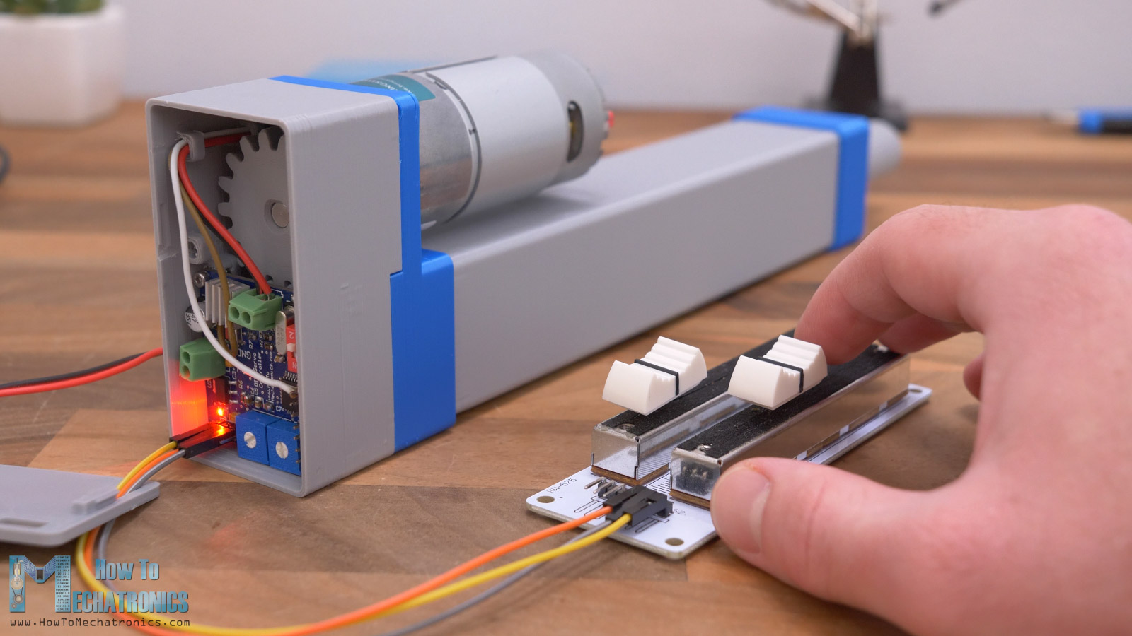
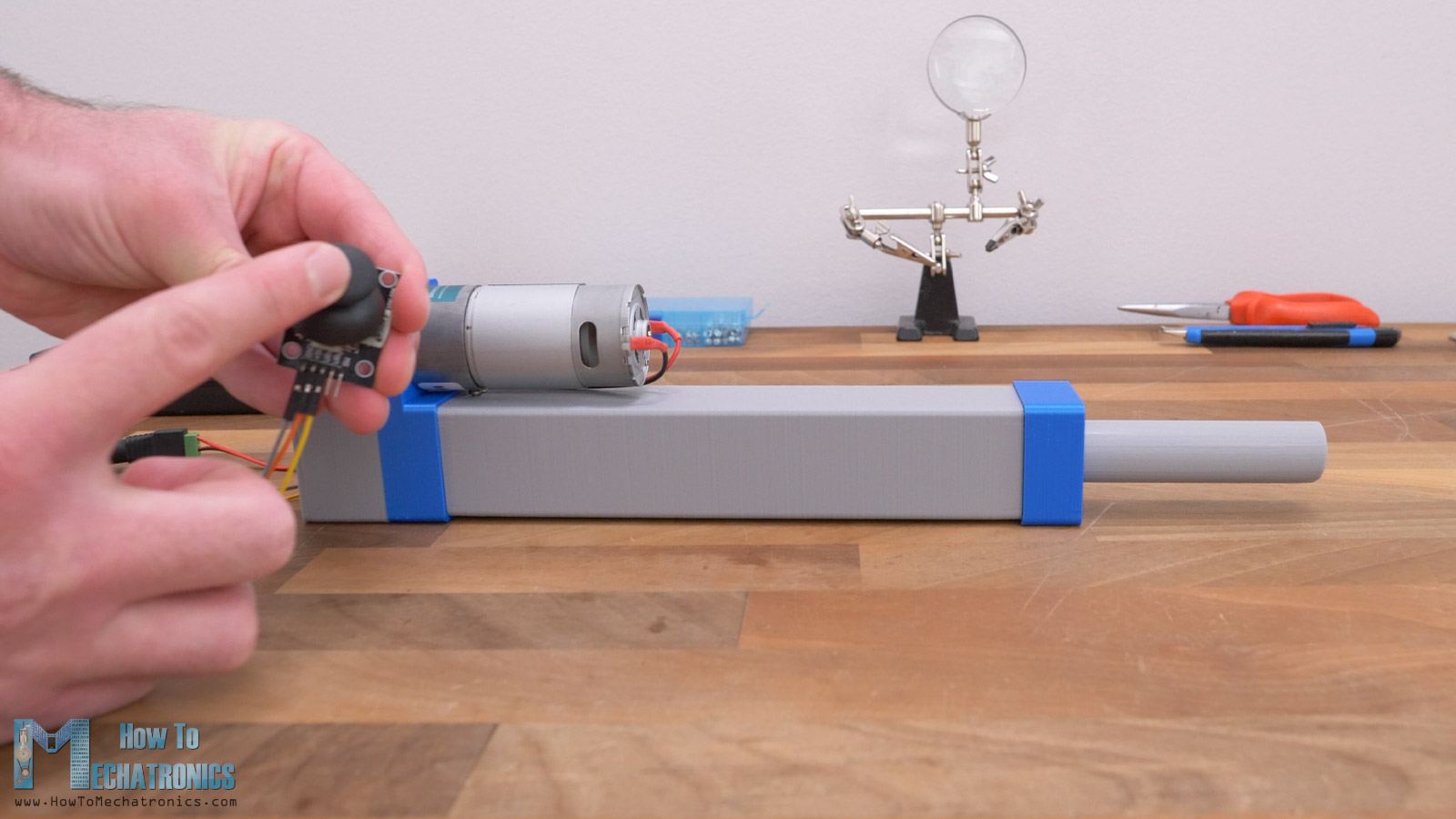
The input for controlling this linear servo actuator can be either analog or digital. In the case of an analog input, it can be any type of potentiometer like shown here. A linear potentiometer, a common rotary potentiometer or for example a joystick which is again a rotary potentiometer and so on.
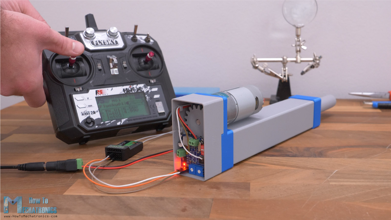
In the case of digital input, we can control the actuator with an RC Transmitter. Of course, for this setup we also need an RC receiver which goes as an input to the actuator.
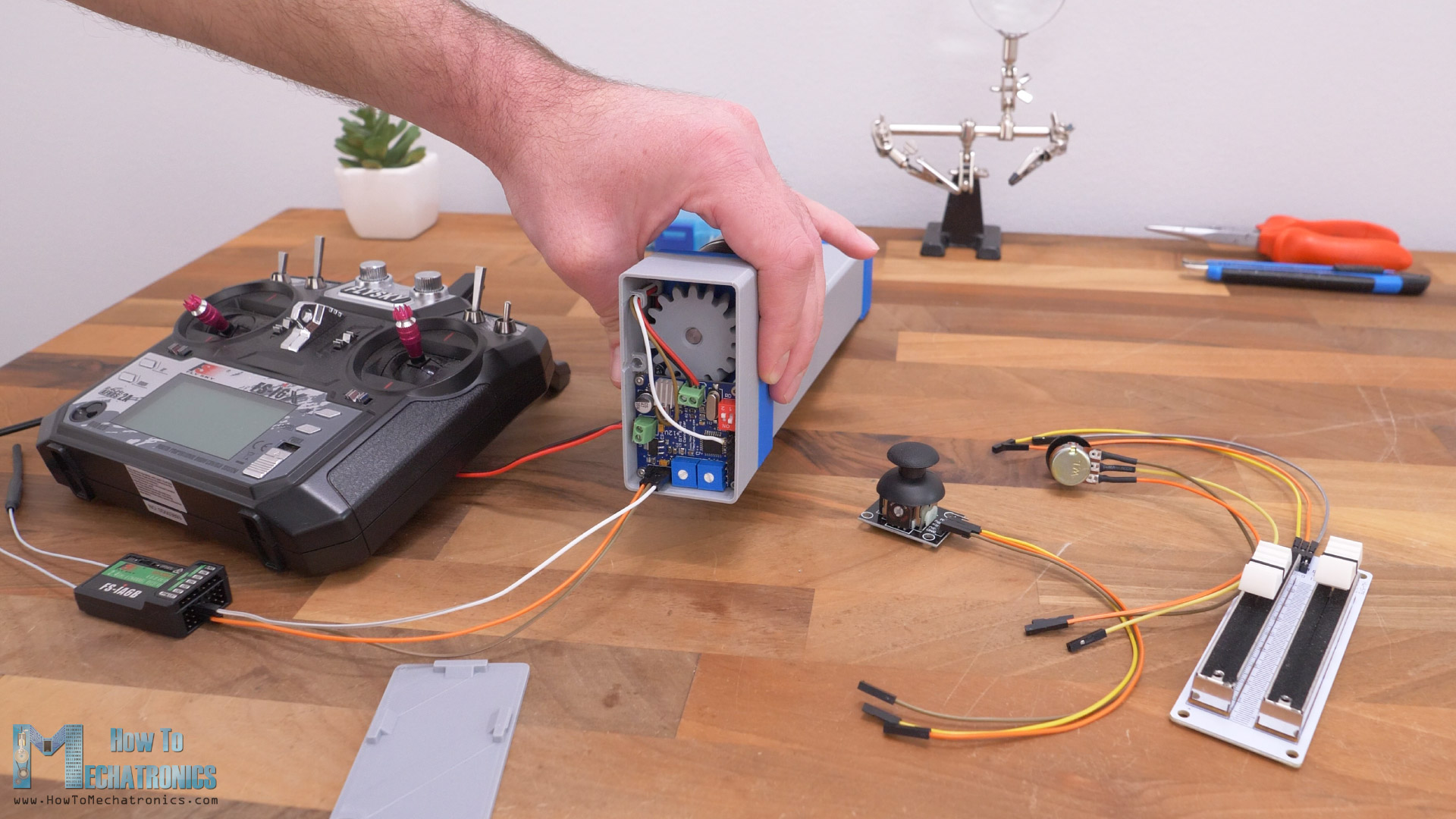
For both these analog and digital input modes, we only need 3 wires to make a connection, 2 of which are for powering the input device, and the 3rd one is for the input signal.
A cool feature this custom-built linear servo actuator has is that we can set a custom start and end position for the output rod as well as adjust the sensitivity or how quickly the actuator will respond to our input.
Though, my favorite feature is the ability to control this actuator from a PC or a Laptop through a serial port communication. We can enter values in millimeters through the Arduino IDE Serial monitor and the actuator will move to that position.
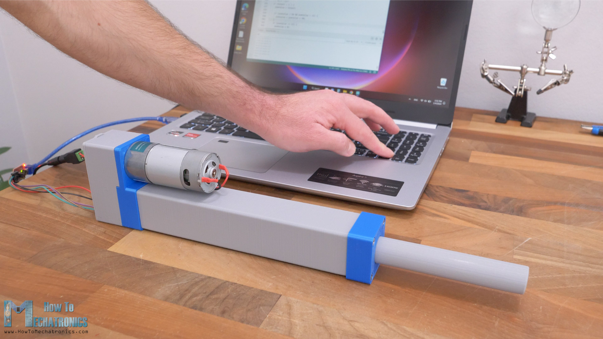
What’s even cooler, we can make repeatable movements, or store the positions, by typing “save” on the serial monitor at each position we want, and then tell the actuator to repeat the movements in a loop, by typing “run” on the serial monitor.
Now let me explain everything you need to know about this custom-built linear servo actuator, how it works and how I designed it, so you can also build one on your own.
How It Works
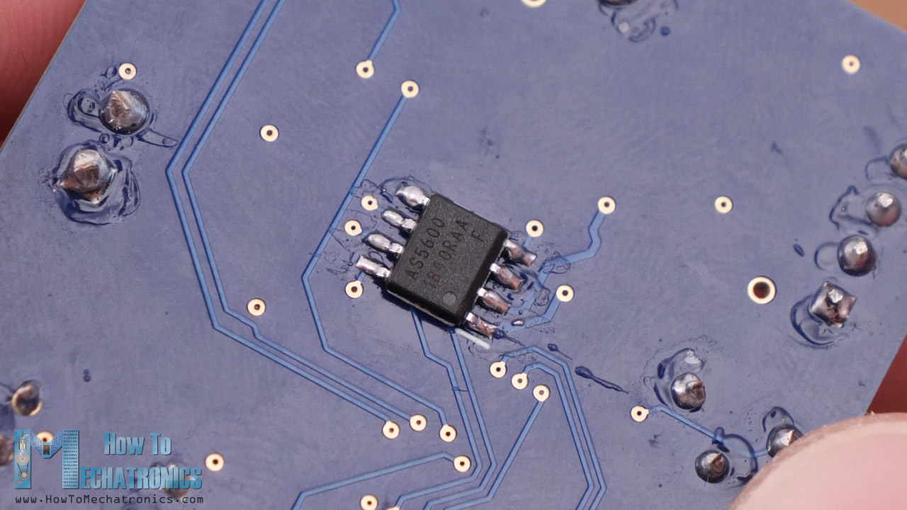
So, the closed loop control system is based on the AS5600 magnetic rotary position sensor and the implemented PID control for driving the DC motor.
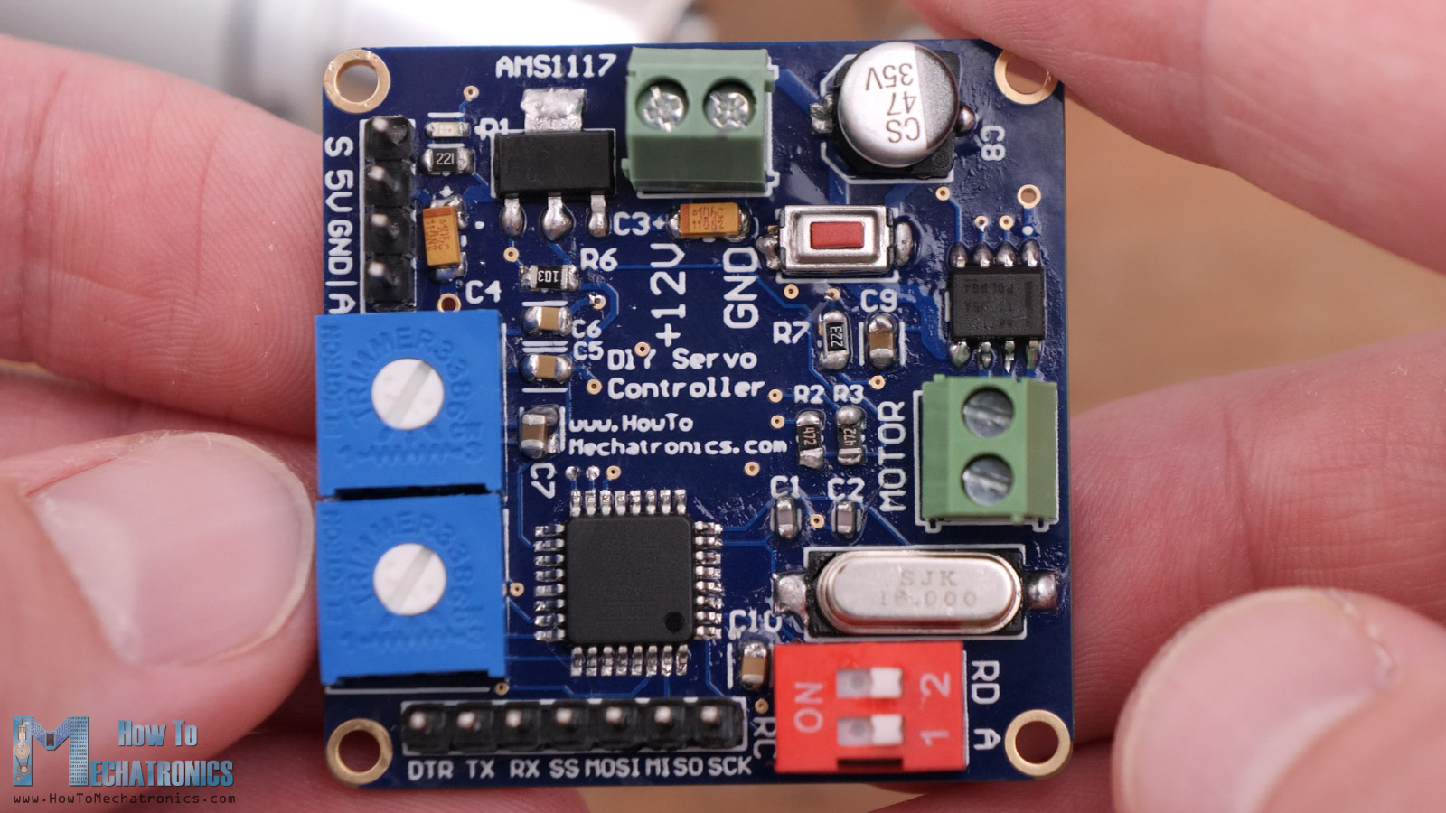
Actually, I’m using the same custom servo motor controller board that I made in my previous video, which includes its own microcontroller and everything else to easily turn any DC motor into a stand-alone servo motor.
You can check that tutorial out for a detailed explanation of how a servo motor and a closed loop control system works.
Real quick, a servo motor is a closed loop control system where the input signal, or the desired position is compared to the actual position of the motor that we get from the position feedback sensor.
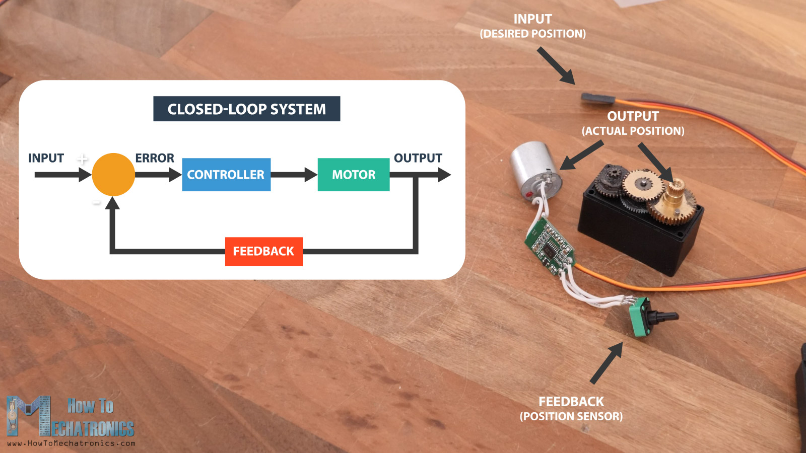
The difference that occurs, which is called the error, is then processed in the controller which commands the motor to move until it reaches that desired position.
So, this linear servo actuator has the same working principle as a servo motor, but with one additional step of converting the rotational motion of motor into a linear motion with the help of a lead screw mechanism.
Linear Servo Actuator Design
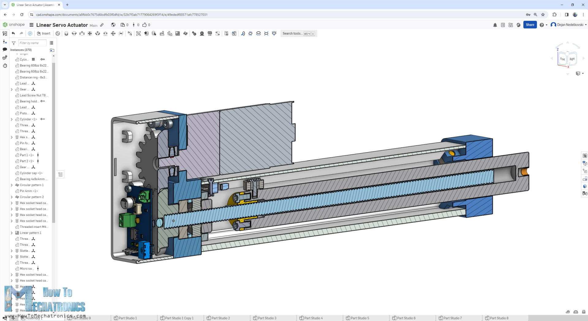
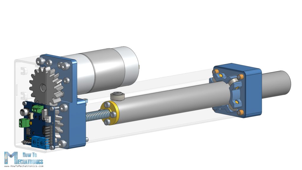
Here’s the 3D model of this linear servo actuator, from where we can see how everything works.
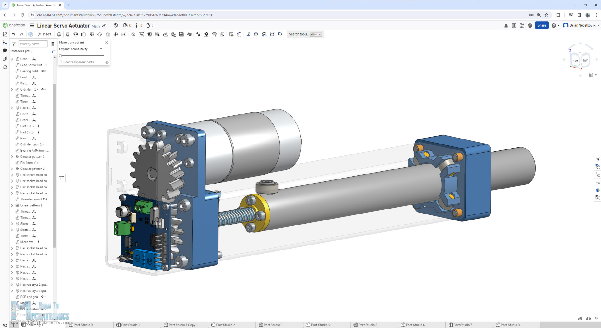
The AS5600 magnetic rotary position sensor is located at the back side of the actuator, and it keeps track of the rotation of the lead screw. The lead screw that I use has 8mm pitch, which means, with each full rotation, the lead screw nut makes 8mm linear motion.
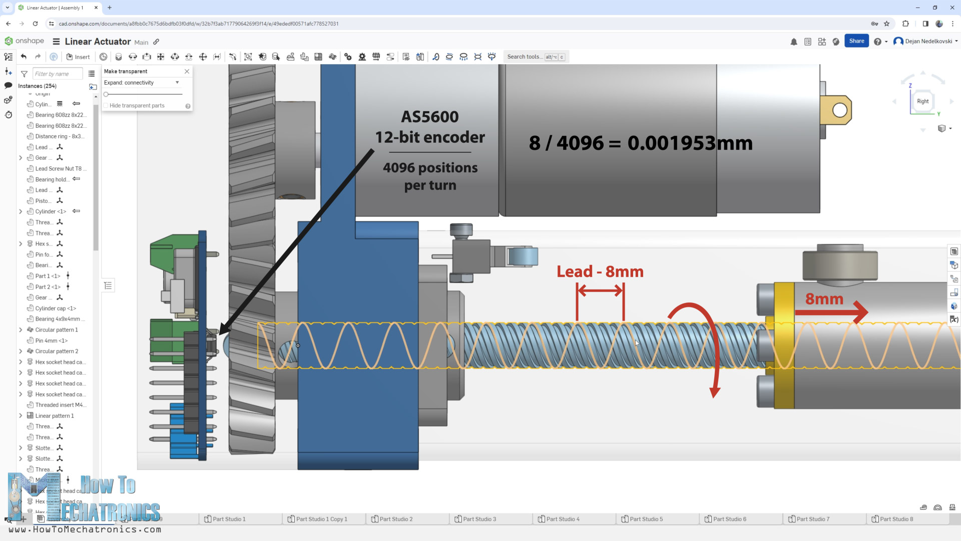
The AS5600 is a 12-bit encoder which means it can output 4096 positions per turn. If we divide 8 by 4096, we get a resolution of 0.001953mm. That’s the smallest change in position that the AS5600 encoder can detect. That’s quite impressive I think.
The DC motor that I use is 12V motor with included reduction gearbox which outputs 480 RPM. If we divide the 480 by 60, we get a value of 8 revolutions per second, and if we multiply that number by 8, because the lead screw has 8mm pitch, we get a linear speed of 64mm/s of the actuator.
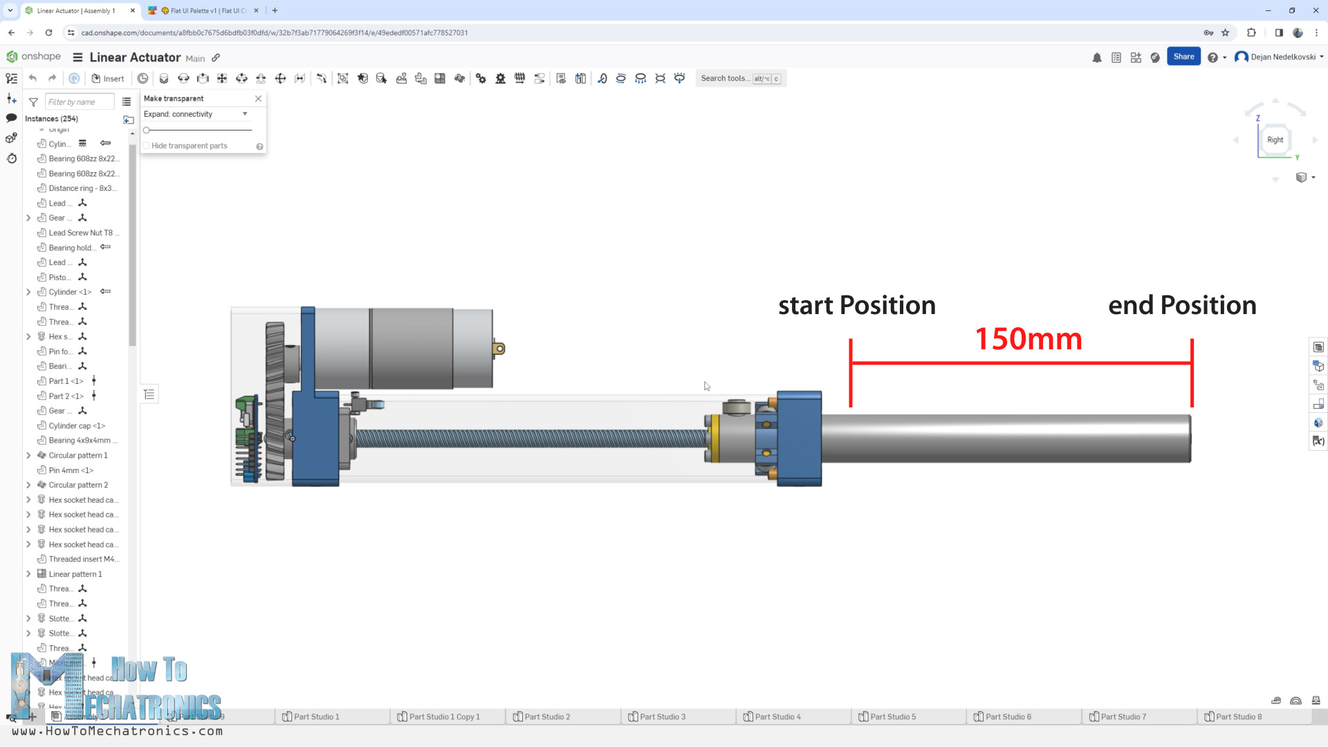
I found that to be on spot, because the maximum travel of this actuator rod is 150mm, so it would take around 2.5s from start to end position at maximum speed, or around 3s if we include the acceleration and deceleration. Therefore, I used 1:1 gearset ratio for driving the lead screw.
The design of the whole linear actuator is based on the size of the custom-built servo motor controller PCB and the lead screw and lead screw nut of course. The PCB had a dimension of 40x40mm, so that was the minimum size of the cylinder block.
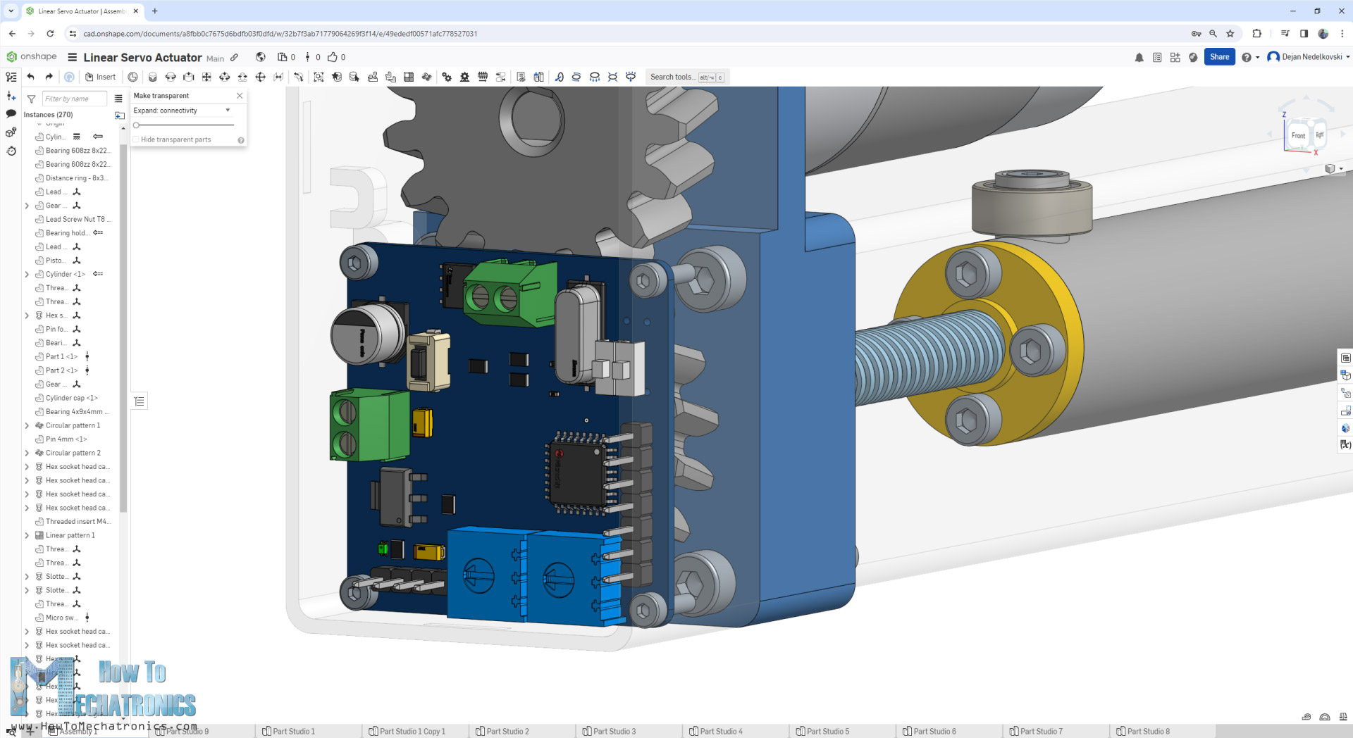
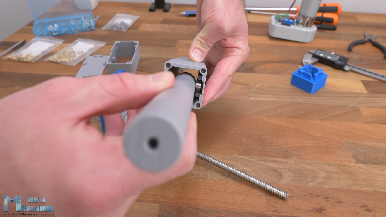
The 8mm lead screw nut had outer dimension of 22mm, so according to it I designed the rod. The nut and the rod are connected with four M3 bolts and threaded inserts. At the top of the rod, there is a bearing that slides on the cylinder block, and it’s used for guiding the rod and preventing it from rotating.
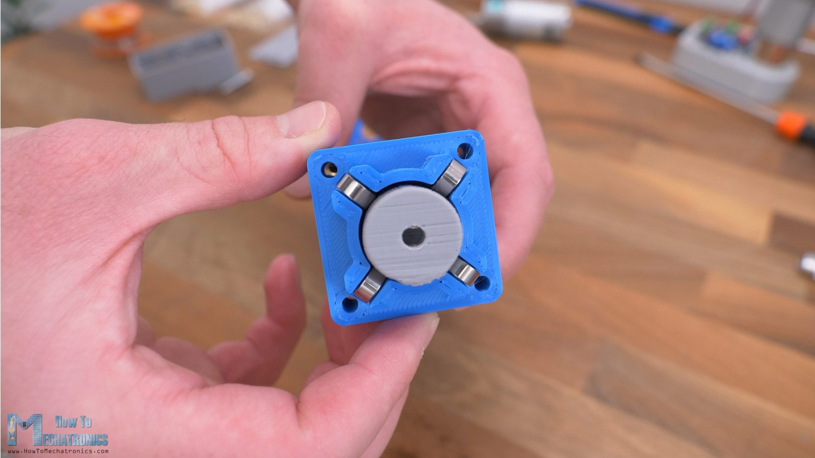
At the output cylinder cap, we have 4 small bearings which guide the rod out of the cylinder block.
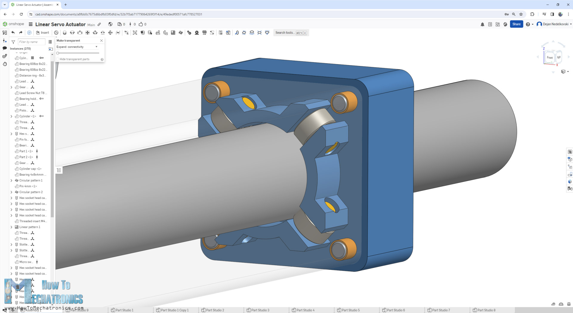
Overall, I think the linear actuator came out compact enough considering all the components used.
I also managed to fit a micro limit switch inside the cylinder block, which is used for homing and setting the start position of the actuator.
3D Model Download
You can view and explore the 3D model of this custom-built linear servo actuator directly on your web-browser with Onshape. (you need an Onshape account for that, you can create a free account for at home use)
You can get the STL files need for 3D printing, as well as the STEP file of this 3D model from Cults3D.
On more thing to mention here is that you can easily increase the maximum travel length of this linear actuator, by simply increasing the length of the cylinder block and the rod. I chose these dimensions because I wanted all the parts to fit on 3D printer with a smaller print bed of 220x220mm. The biggest part here is the rod, which is 215mm long.
3D Printing
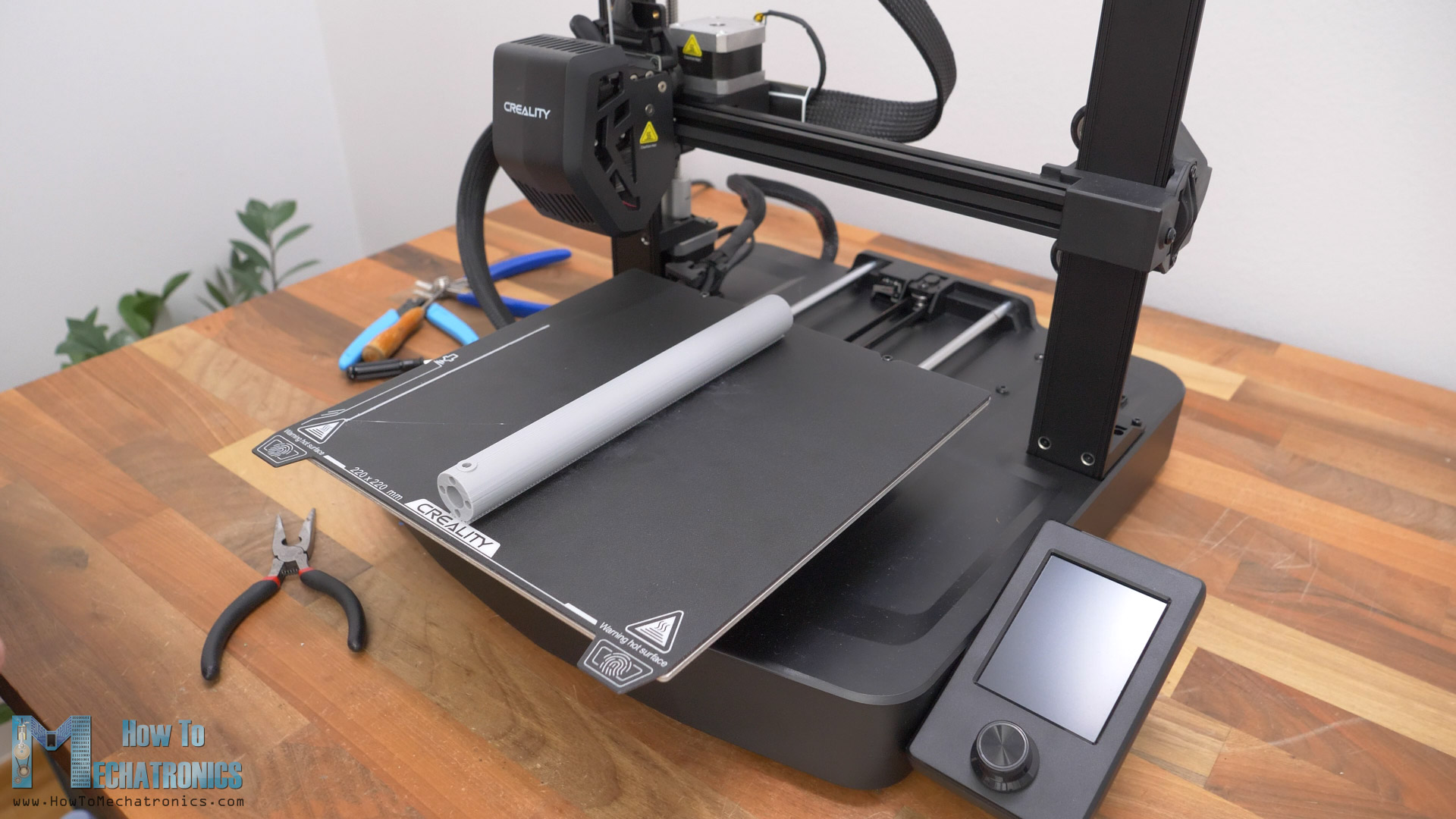
My new Creality Ender-3 V3 SE did a great job of printing it in a horizontal orientation along the Y-axis. Although we need to do a little bit of sending, printing the rod in this orientation will contribute to smoother operation and stronger rod.
When 3D printing it’s important to use the Horizontal Expansion feature in your slicing software in order to compensate for the expansion of the filament and get more dimensionally accurate parts.
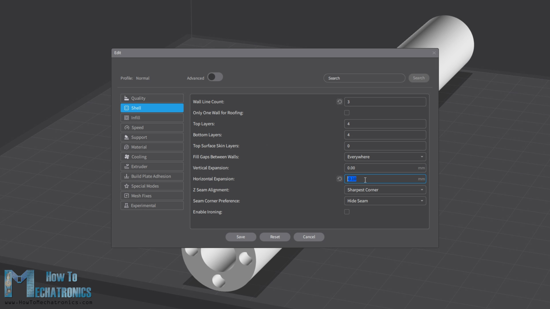
I used a value of –0.1mm, but you should do some test prints to see what value will suit your 3D printer.
I printed the cylinder block along the Z-axis to avoid printing a lot of support material. The Creality Ender-3 V3 SE also did a great job for this print as well.
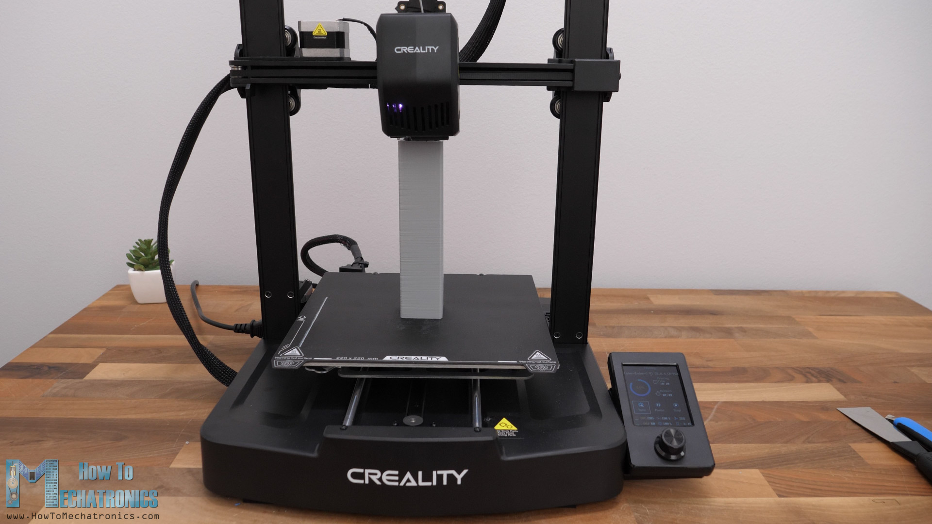
I was pleasantly surprised by the print quality this 3D printer offers considering its price point. It’s super easy to set up the 3D printer, it has auto bed leveling, direct extruder, great print quality and increased printing speeds of up to 250mm/s. All of this for just under $200 makes it one of the best 3D printers for those how are on a budget.
Check out this 3D Printer on the Creality store or Amazon. Also check out my detailed review on it on my website.
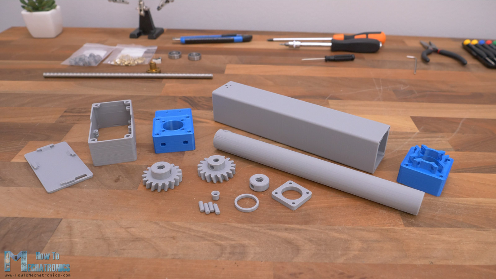
Assembling
Anyway, here are all 3D printed parts, so we can now start with assembling the linear actuator.
Parts list
You can get the components needed for this Linear Servo Actuator project from the links below:
Mechanical:
- Lead Screw 8mm Tr8x8 ………………………………………….. Amazon / AliExpress
- Ball bearing 8x22x7mm ………………………………………. Amazon / AliExpress
- Ball Bearing 4x9x4mm x 4 …………………………………….. Amazon / AliExpress
- Ball bearing 6x13x5mm 686-2RS x1 ……………..….. Amazon / AliExpress
- M3x5mm and M4x5mm threaded inserts ……….. Amazon / AliExpress
- M3 and M4 bolts and nuts ……………….…………….…. Amazon / AliExpress
Bolts: M3x8 – 10pcs; M3x10 – 2pcs; M3x10 countersink – 1pcs; M4x6 – 2pcs; M4x25 – 2pcs; M4x30 – 2pcs; M2x8 – 6pcs; M4x5 grub screw – 5pcs
Electronics:
- AS5600 magnetic encoder ………………….. Amazon / AliExpress
- DRV8871 DC motor driver ……………….…. Amazon / AliExpress
- Atmega328p-AU …………………………………. Amazon / AliExpress
- 16Mhz crystal oscillator …………………….. Amazon / AliExpress
- AMS1117 5V voltage regulator ………..…. Amazon / AliExpress
- 3386P square potentiometer ………………. Amazon / AliExpress
- Capacitors 0805 kit …………………………….…. Amazon / AliExpress
- 12V DC motor – ~ 50RPM …………….……. Amazon / AliExpress
Disclosure: These are affiliate links. As an Amazon Associate I earn from qualifying purchases.
Assembling the lead screw mechanism
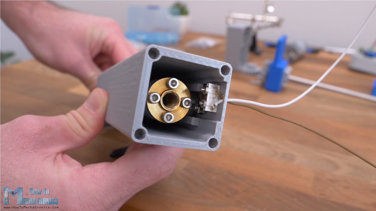
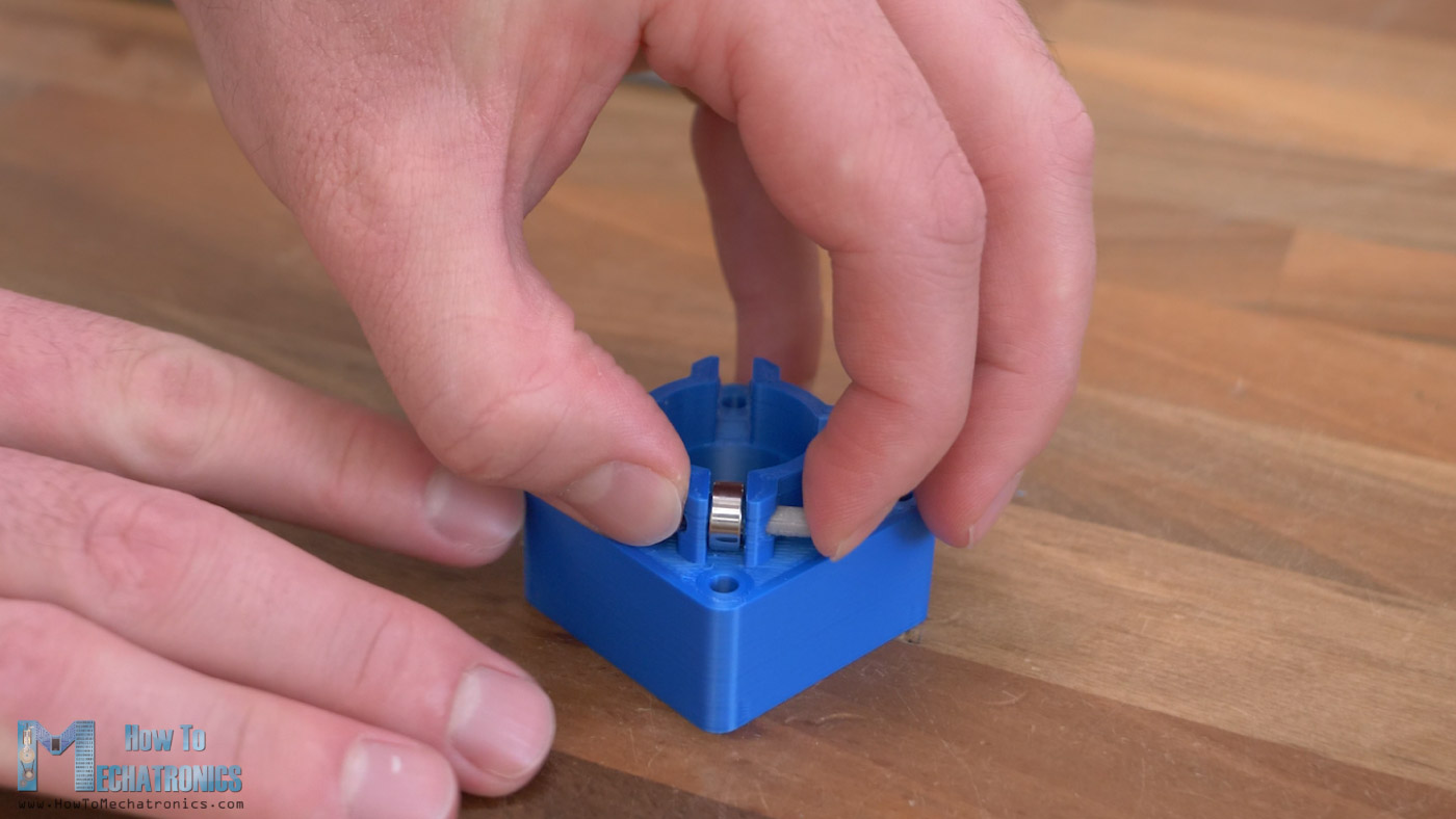
First, we need to install the lead screw in place in the cylinder base block. For that purpose, first we need to insert this 3D printed nut which has the same thread as the lead screw.
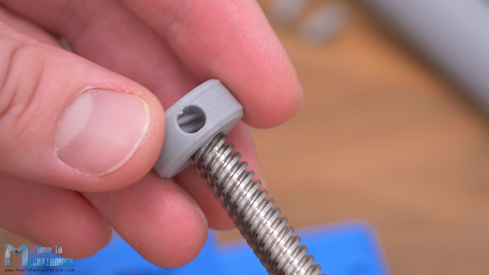
It’s a bit hard to screw the nut onto the lead screw as it’s a tight fit, but that’s what we need here. This nut holds the entire force when the rod is pushing, so the tighter the fit, the more force will be able to hold. In addition to that, the nut also has a hole for inserting a threaded insert for securing it to the shaft with a grub screw.
The leadscrew is held in place in the cylinder base block with the help of two ball bearings with 22mm outer diameter.
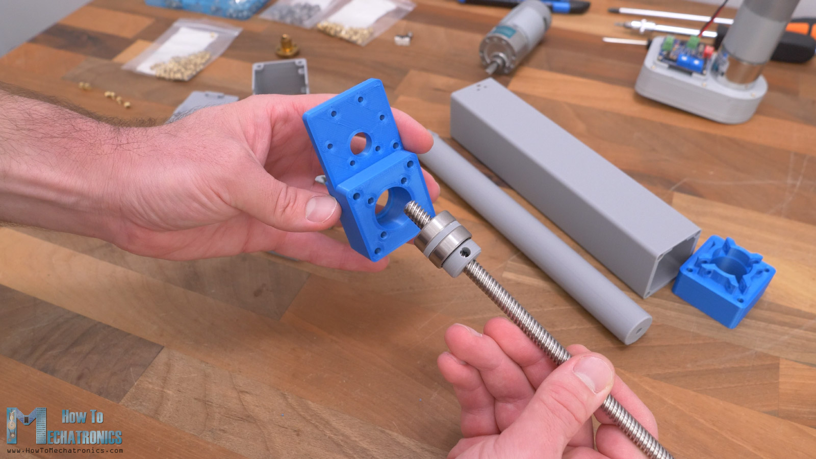
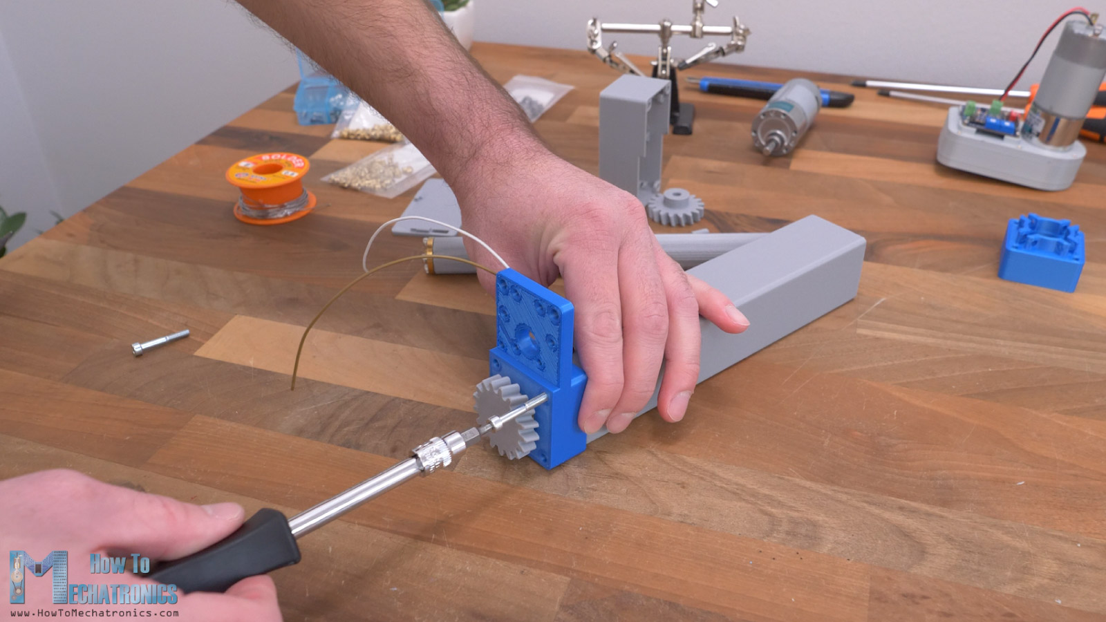
At the back side goes the gear that drives the lead screw. This gear also has a matching thread and two holes for threaded inserts for securing it to the lead screw with grub screws.
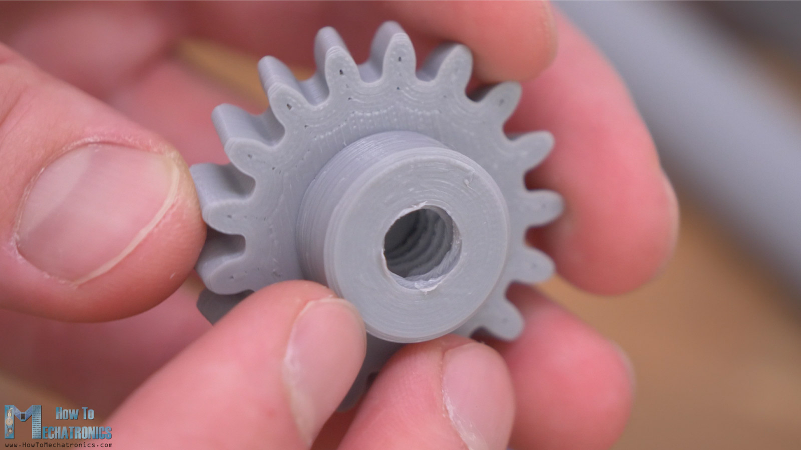
This connection is also critical as it transfers the entire torque of the motor to the lead screw, so it must not slip.
To make this sub-assembly, first we need to install the threaded inserts in place on the gear and the nut, as well as some on the cylinder block.
We screw the gear and the nut in the opposite direction but not too tight as this adds axial forces to bearings. Then using some grub screws, we can secure the nut and the gear to the lead screw.
Once secured, we can notice that the lead screw is not yet fixed in place. We need to add this plate to the cylinder block which will ensure the bearings will stay in place in the cylinder block.
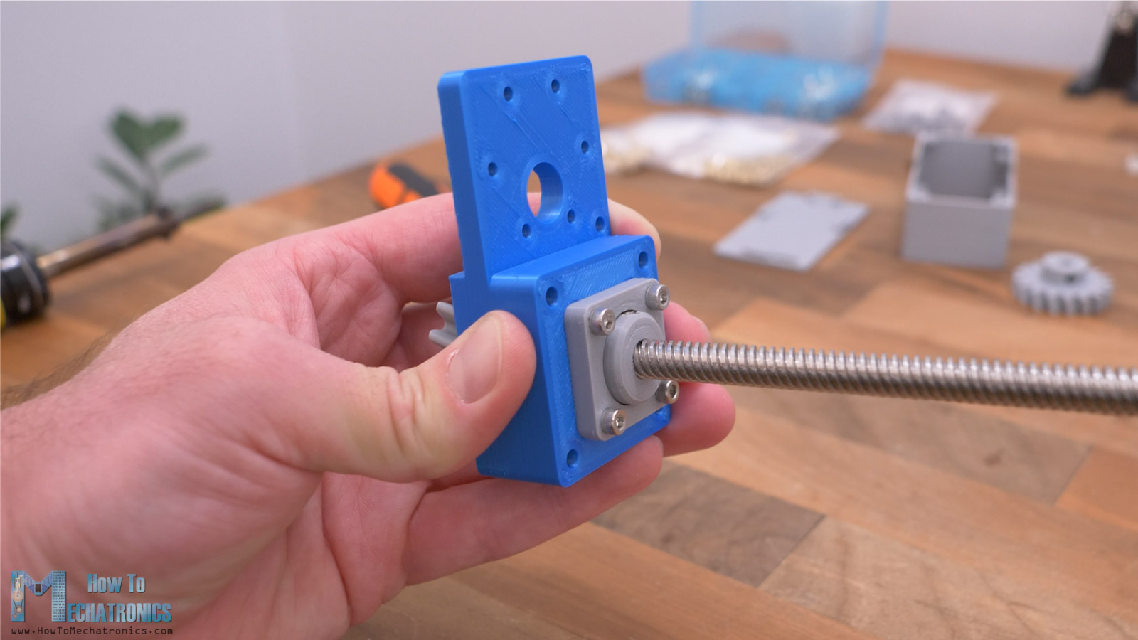
This completes this sub-assembly; the lead screw now stands firmly in place while it can freely rotate.
Next, we can prepare the rod. The rod is hollow throughout its entire length to accommodate the lead screw. For connecting the lead screw nut and the rod, first we need to install some threaded inserts.
At the top side of the rod, we need to install the guide bearing with 13mm outer and 6mm inner diameter.
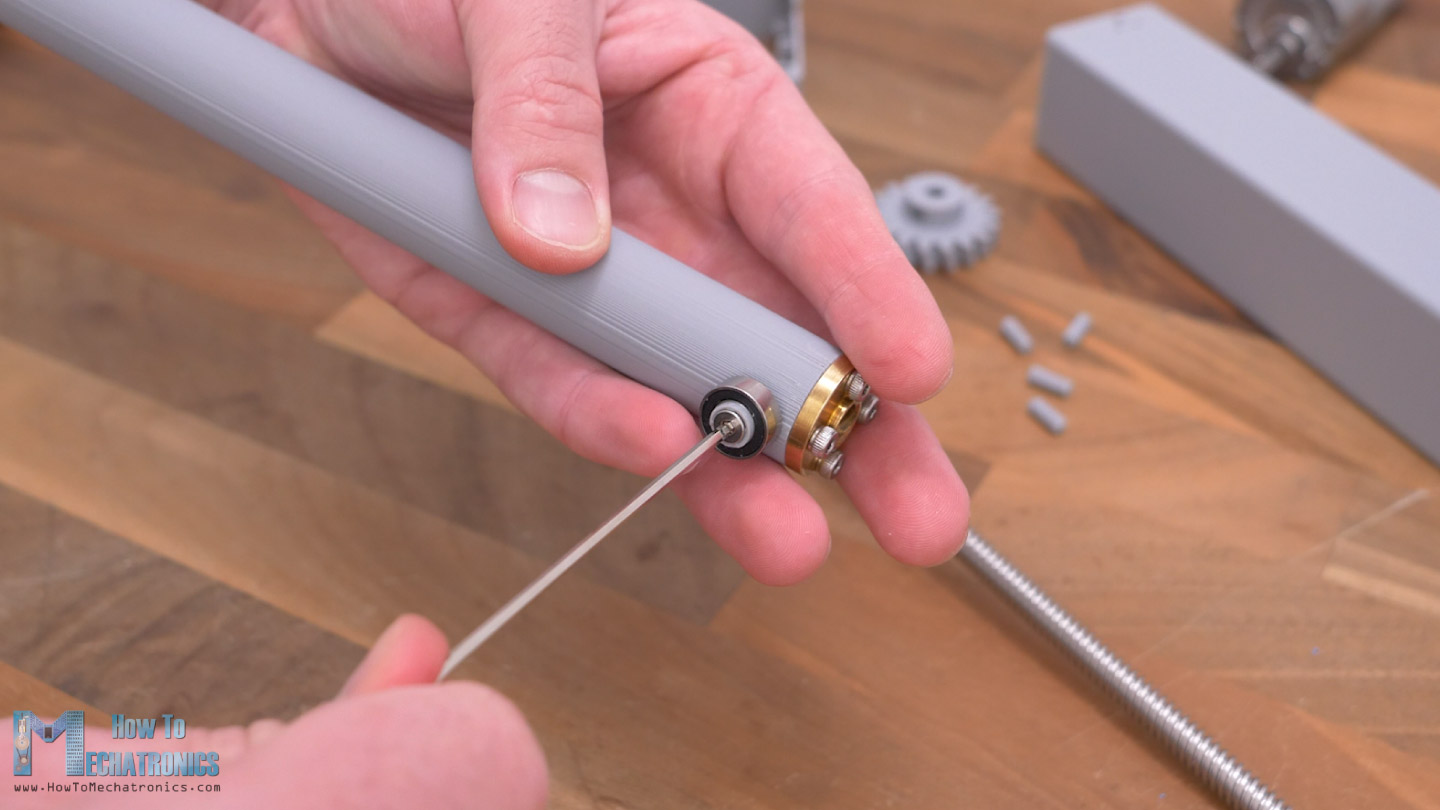
We place the bearing on a 3D printed 6mm hollow shaft and secure it to the rod with an M3 countersunk screw with 10mm length. The rod is now ready and we can see how it will slide in the guide rails of the cylinder.
Next, we need to attach the cylinder to the cylinder base block. Before we do that though, we should install the micro limit switch in place.
First, we need to solder the wires to it, at the NC connection. The wires should be around 15cm long. The wires are passed through a hole at the top of the cylinder, and then we can secure the micro limit switch to the cylinder with the help of two M2 bolts with 8mm length.
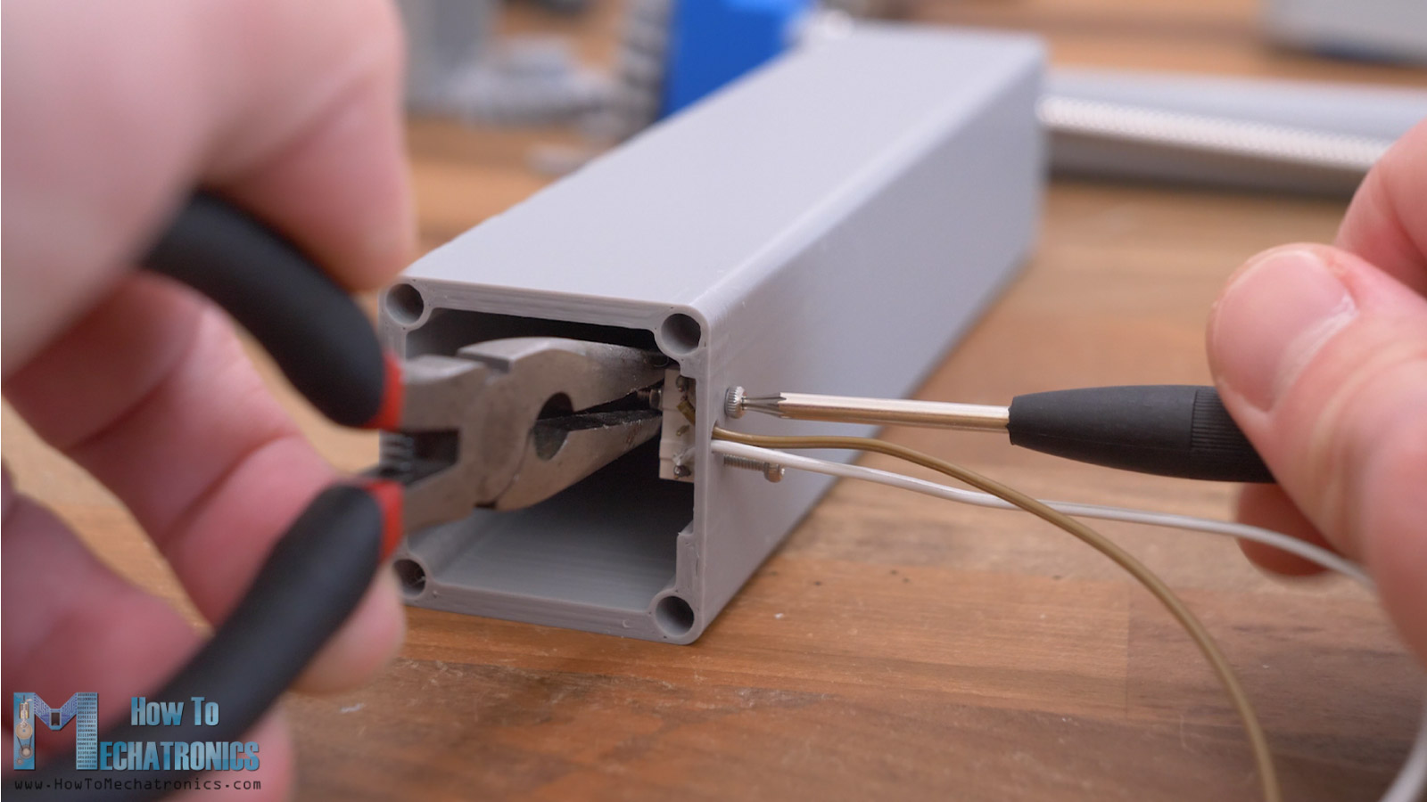
You will need specifically this micro limit switch in order the guide bearing to trigger it just at the right time, without hitting something else.
If you can’t find the exact limit switch model, of course, you can modify the holes and the mechanism.
In order to attach the cylinder to the base block we need to install some threaded inserts here. Then we can secure it in place using two M4 bolts with 25mm length. We should insert just the upper two bolts at this time.
The lower two will go a bit later when installing the gearbox and PCB cover because the same holes are used for securing the cover.
Next, we can screw the rod into the lead screw. The guide bearing should go in-between the guide rails on the cylinder.
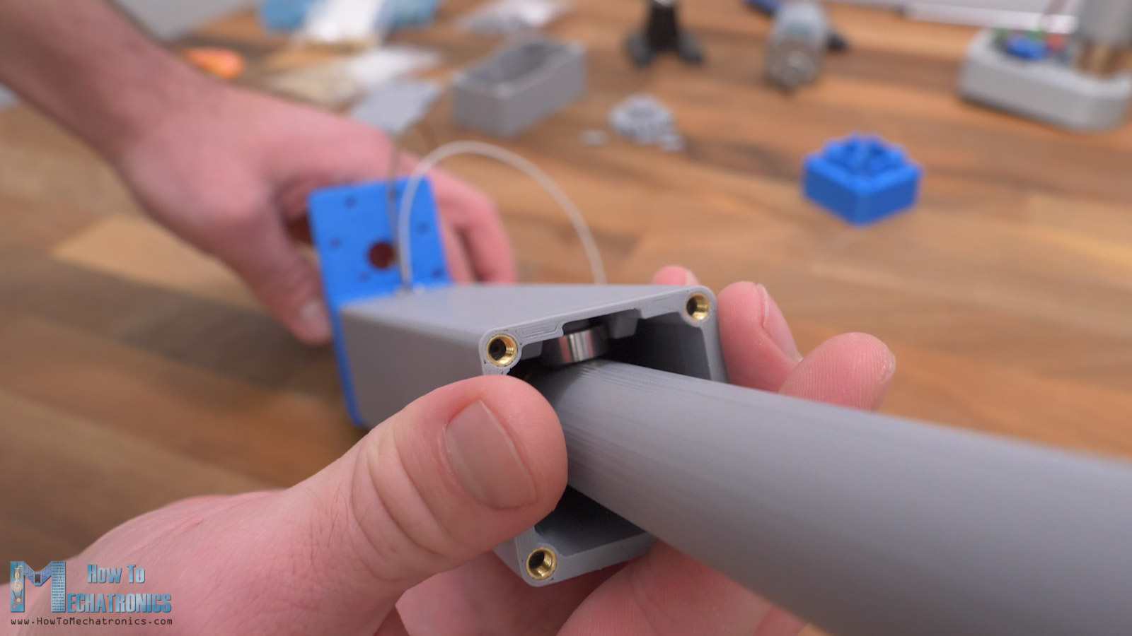
By rotating the gear at the back side, the rod will move backward, all the way until it reaches the micro limit switch.
Then, we can attach the cylinder cap in place. The cylinder cap will accommodate four small bearings with 9mm outer diameter. The shafts for these bearings can be 3D printed.
We should be careful when inserting them in place, as the part where these shafts go is quite small and it might easily break. It happened a few times to me, so make sure they are easy fit. These bearings will support and guide the rod for smoother operation.
The cylinder cap is secured in place with four M4 bolts.
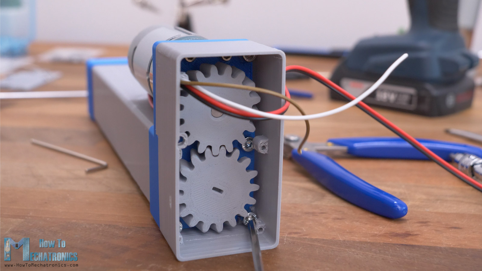
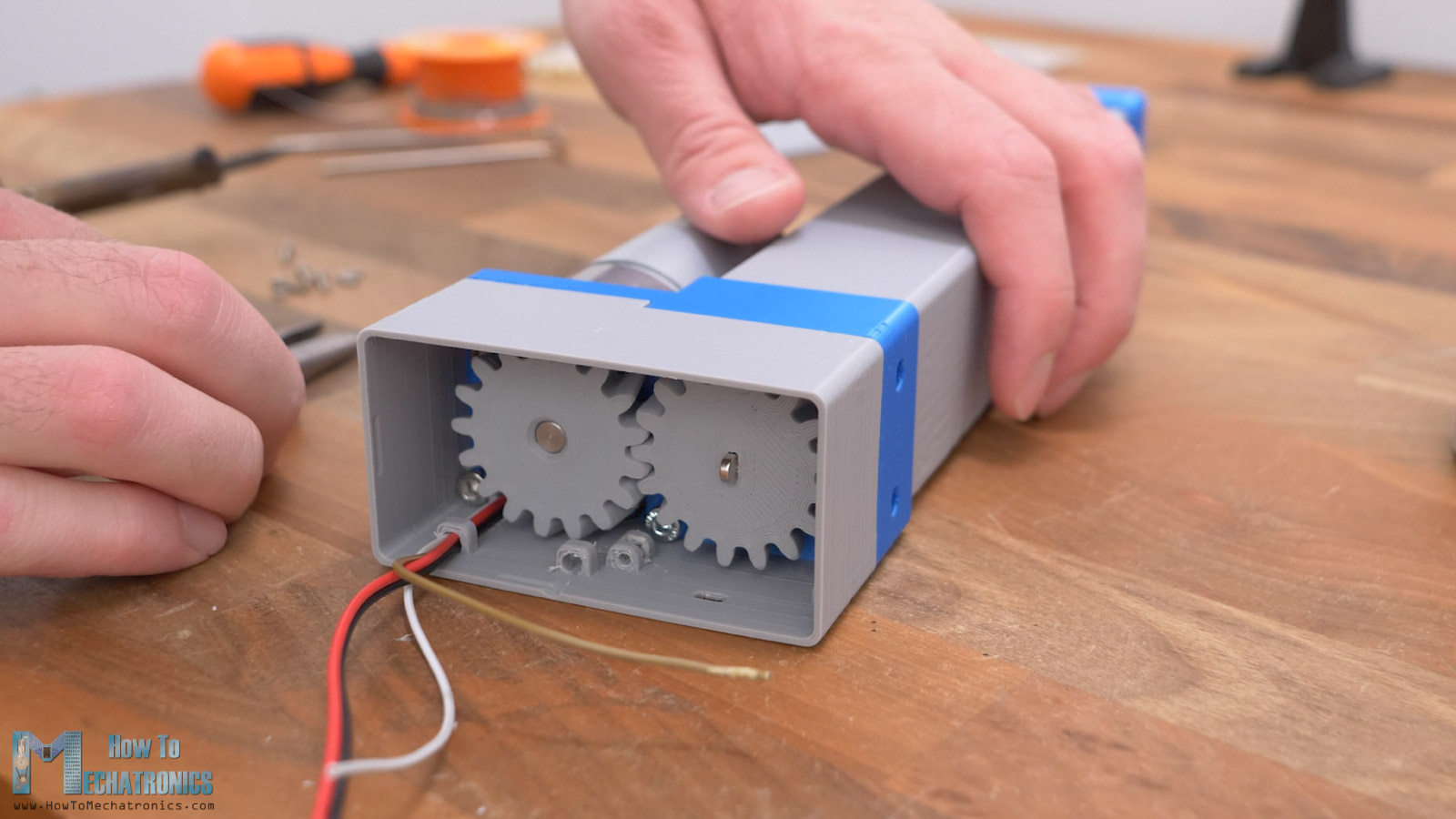
Installing the DC motor
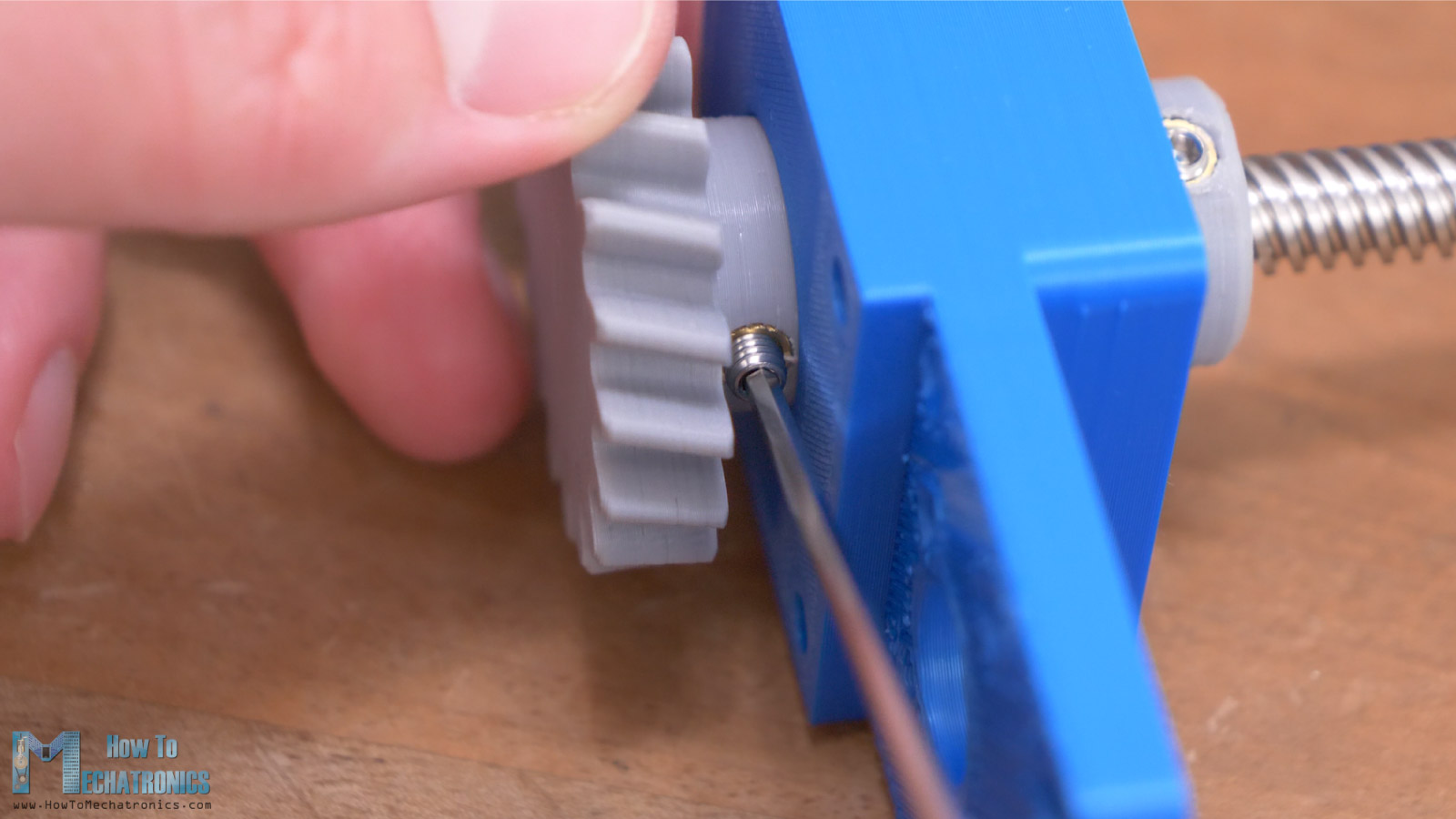
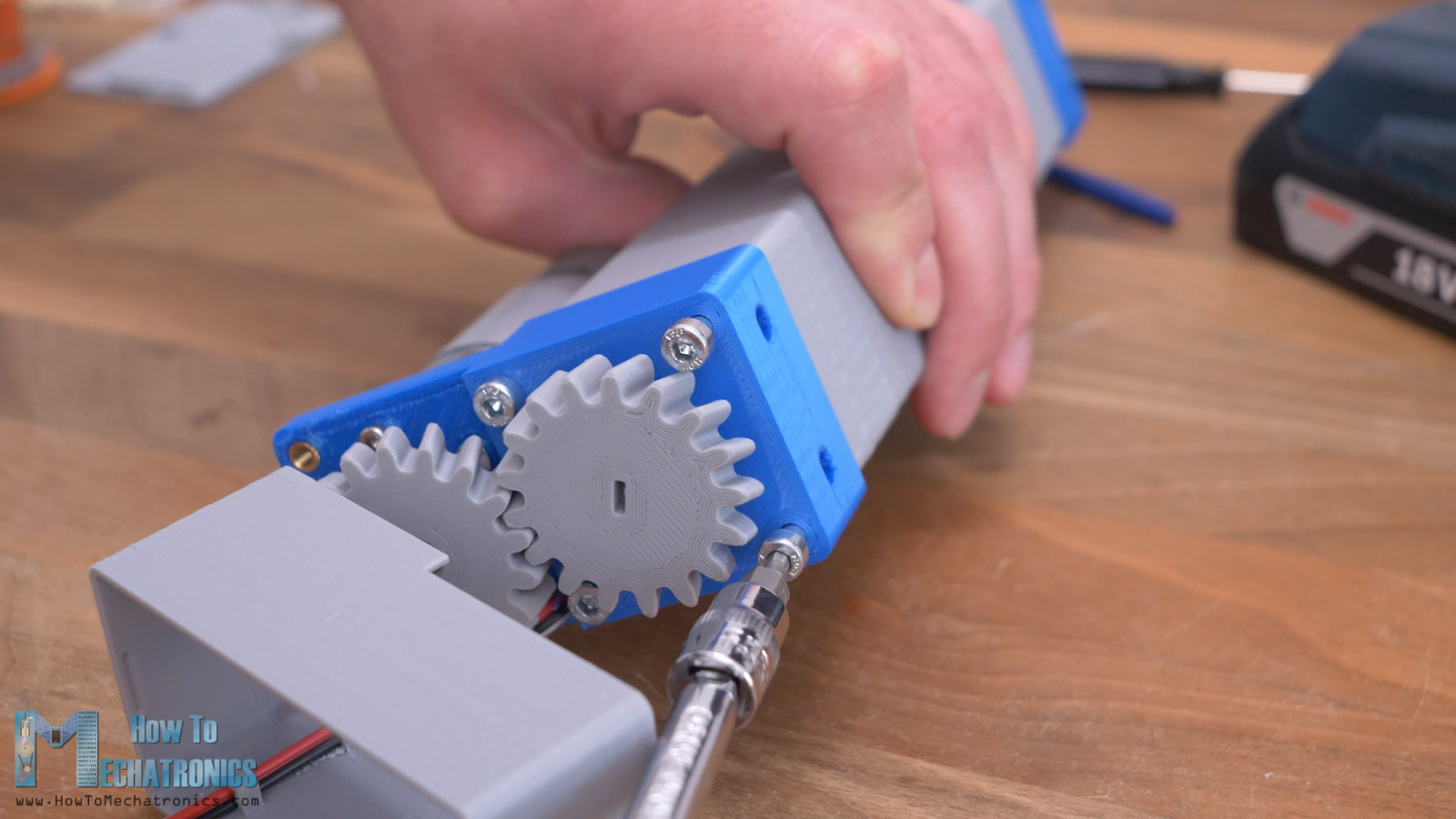
Ok, so next we can insert the DC motor in place. We secure the DC motor with six M3 bolts. Then we can install the gear onto the motor shaft.
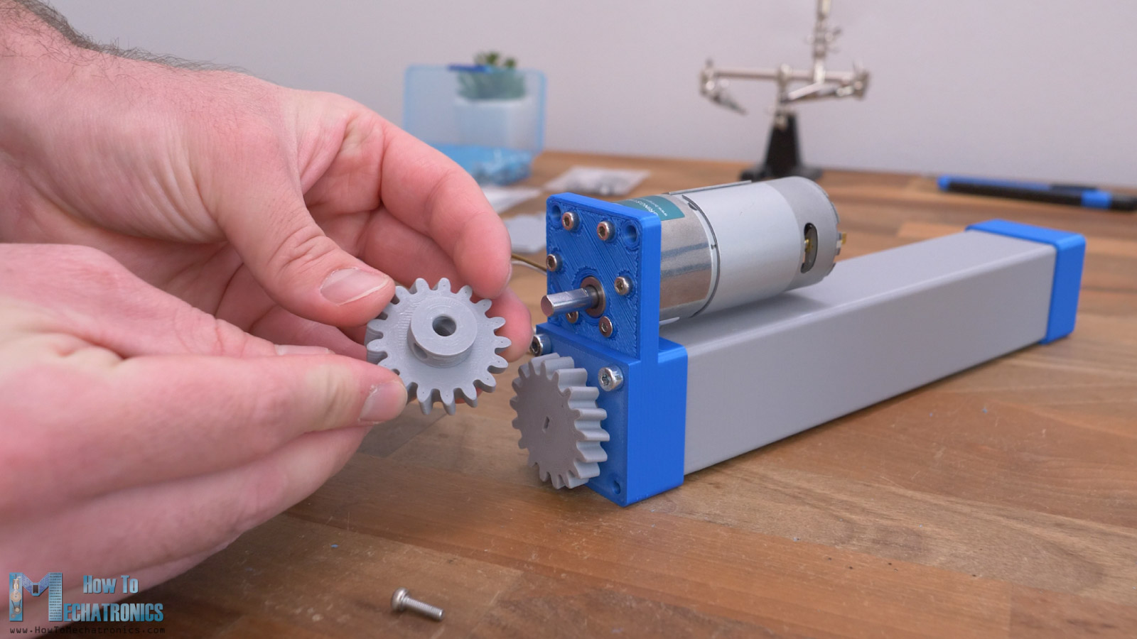
For securing the gear in place we use two threaded inserts and grub screws.
Once the gears are properly paired, we can move on with attaching the gears and PCB cover at the back side of the linear actuator. For that purpose, first we need to install a few more threaded inserts into the cylinder base block.
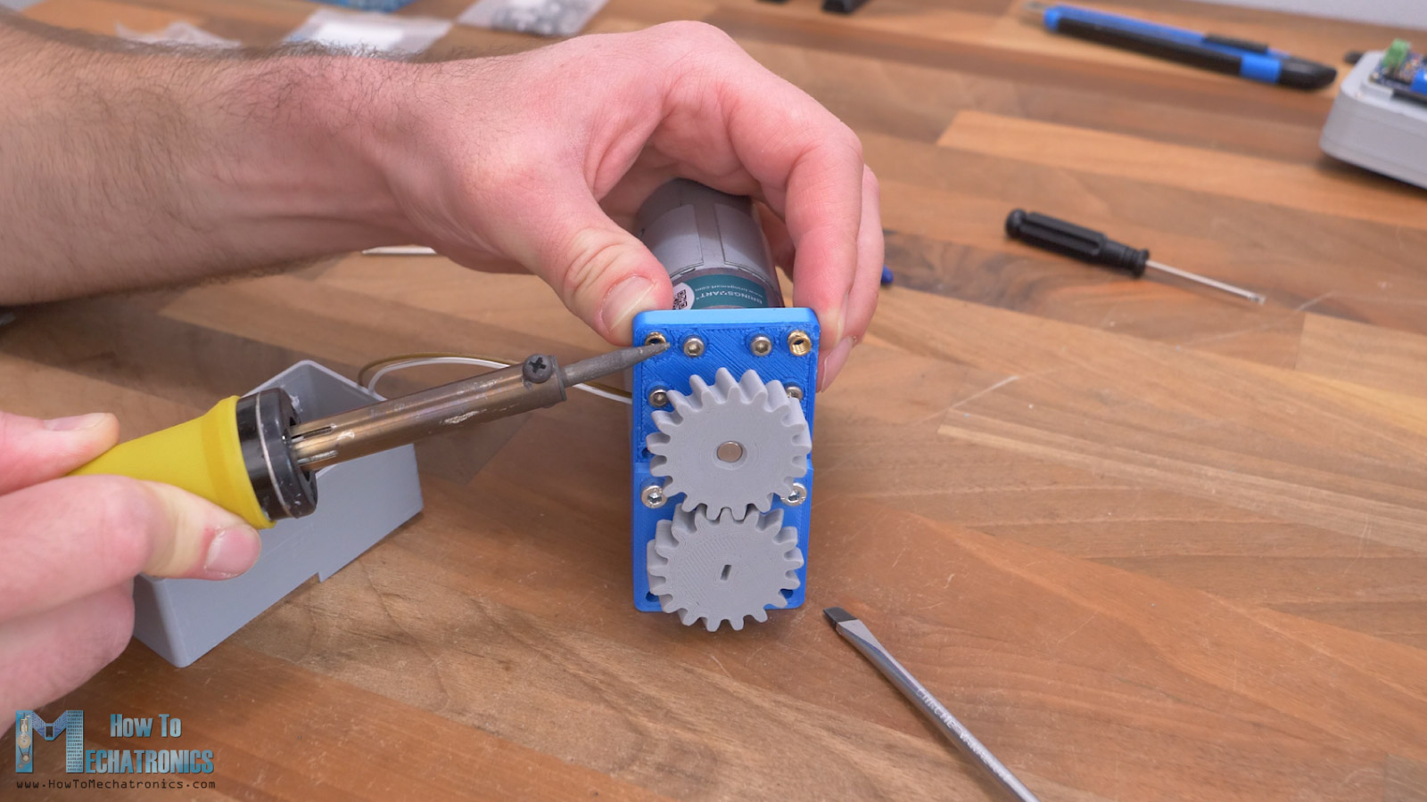
Then we can connect the wires to the DC motor. In my case I directly soldered them to the DC motor.
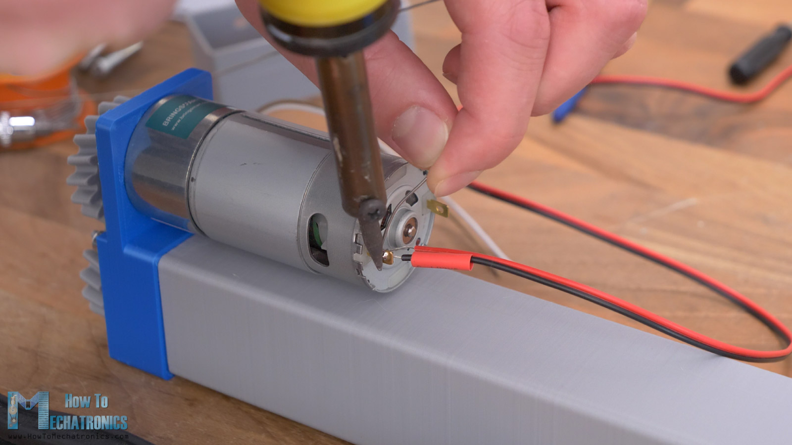
The length of the wires should be around 20cm. There is a hole in the cylinder base block through which we should pass the wires of both the DC motor and the limit switch.
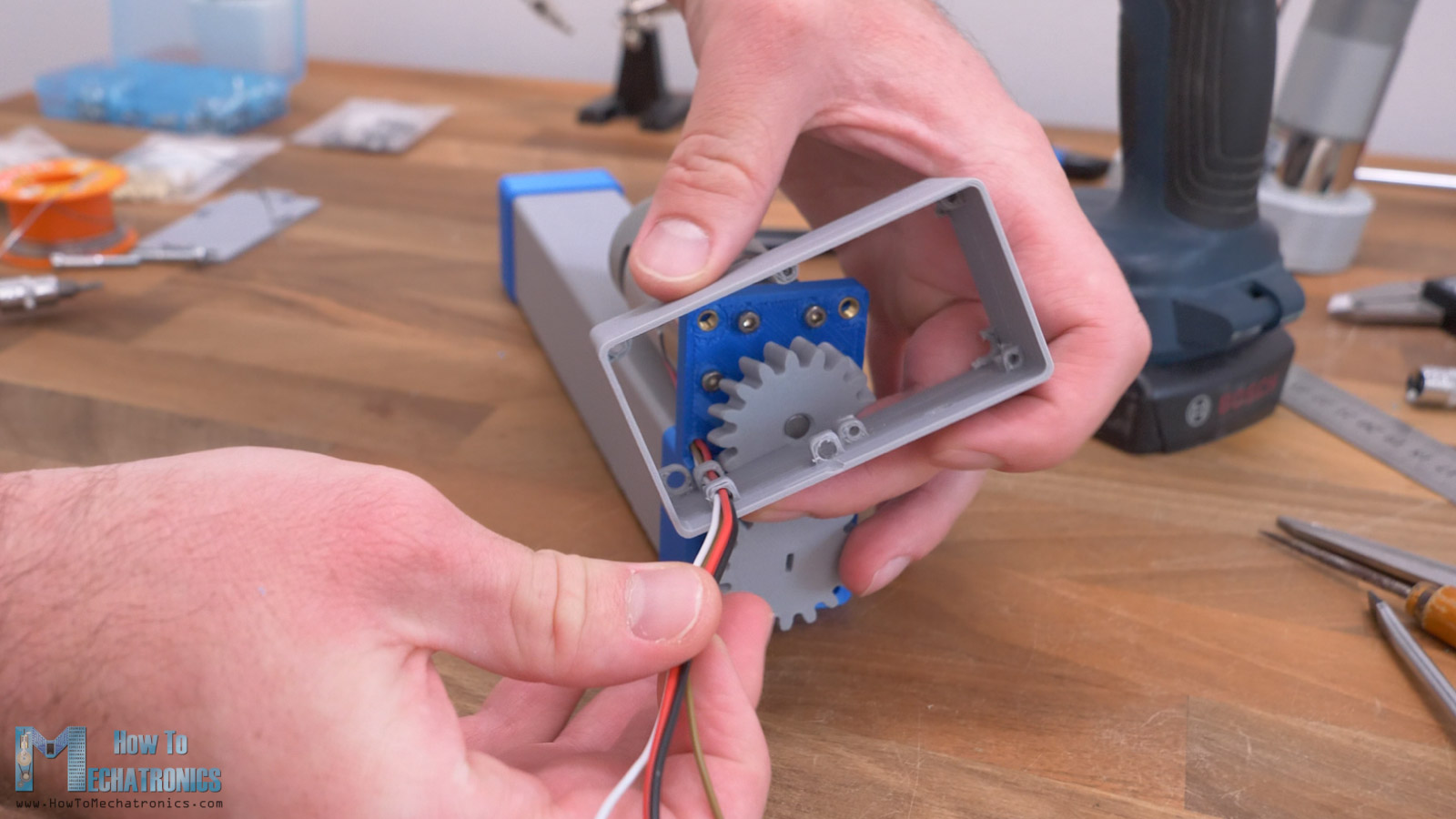
Then we should also pass them through two holders on the cover, which will make sure they stay away from the gear.
At this point, we can secure the cover to the base block. For the purpose, first we need to insert the two M4 bolts at the bottom side, but not all the way in.
We should leave around 2mm or 3mm, so that we can place the cover holder in-between, and then fasten those bolts together with the cover.
This whole operation is a bit messy, but it had to be like that because I wanted the cover to be as small as possible and a single print, and the PCB holders were blocking the way of the bolts.
Installing the custom servo controller PCB
Anyway, once we are done with the cover, we can install the custom servo motor controller board in place. Like I said, it’s the same controller from my previous video where I showed you how you can turn any DC motor into a servo motor.
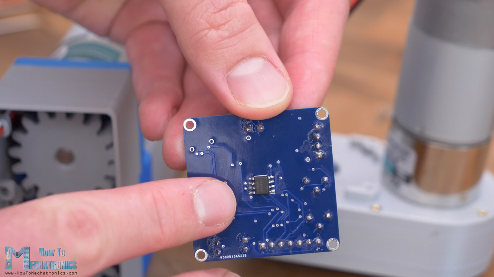
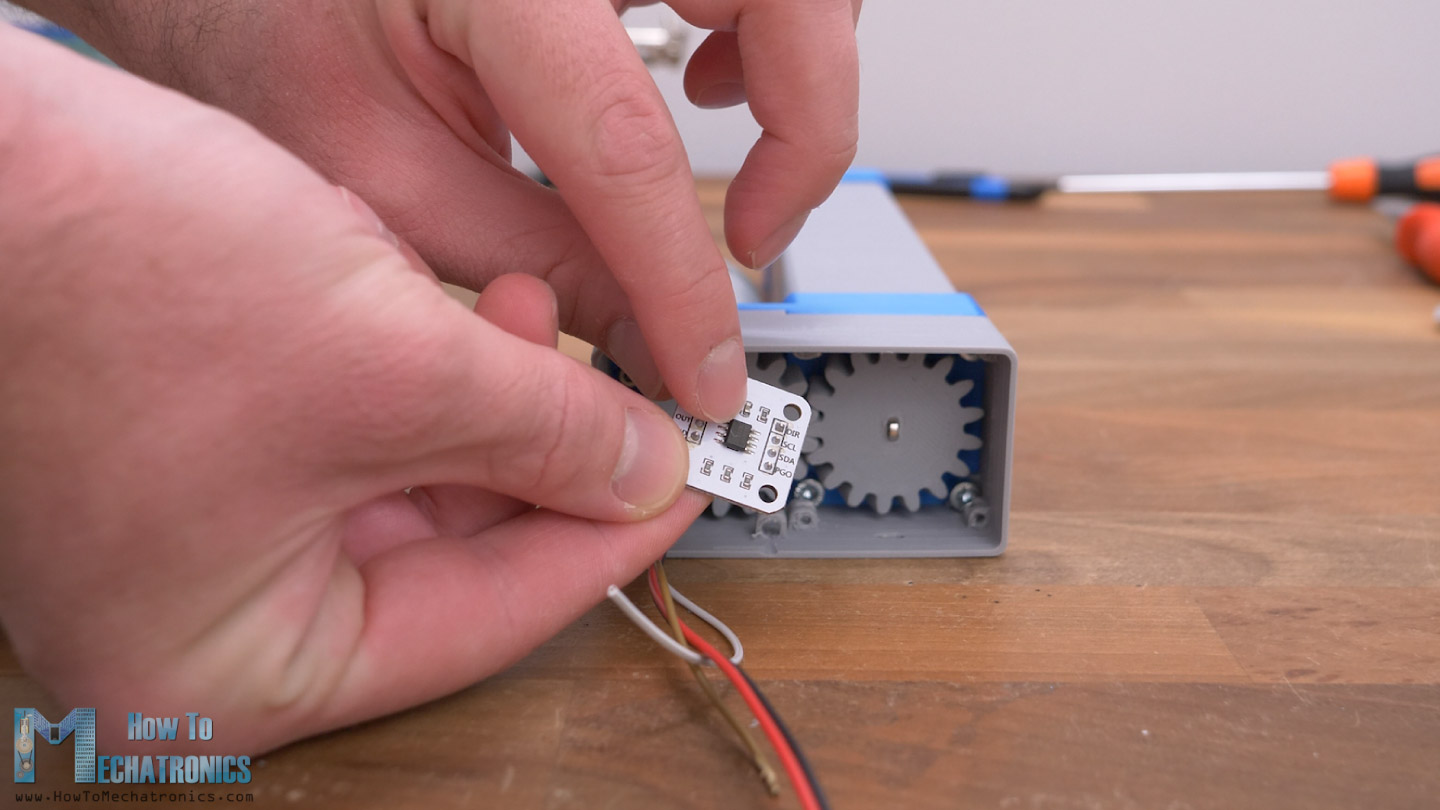
The main component here is the AS5600 magnetic rotary position encoder, which keeps track of the angular position of the magnet attached at the output shaft. In this case we will attach the magnet to the output gear on the lead screw. The magnet gets perfectly aligned with the AS5600 sensor when the PCB goes in place.
For securing the PCB first we need to insert M2 nuts in the holders’ slots, and then tighten the PCB with four M2 bolts.
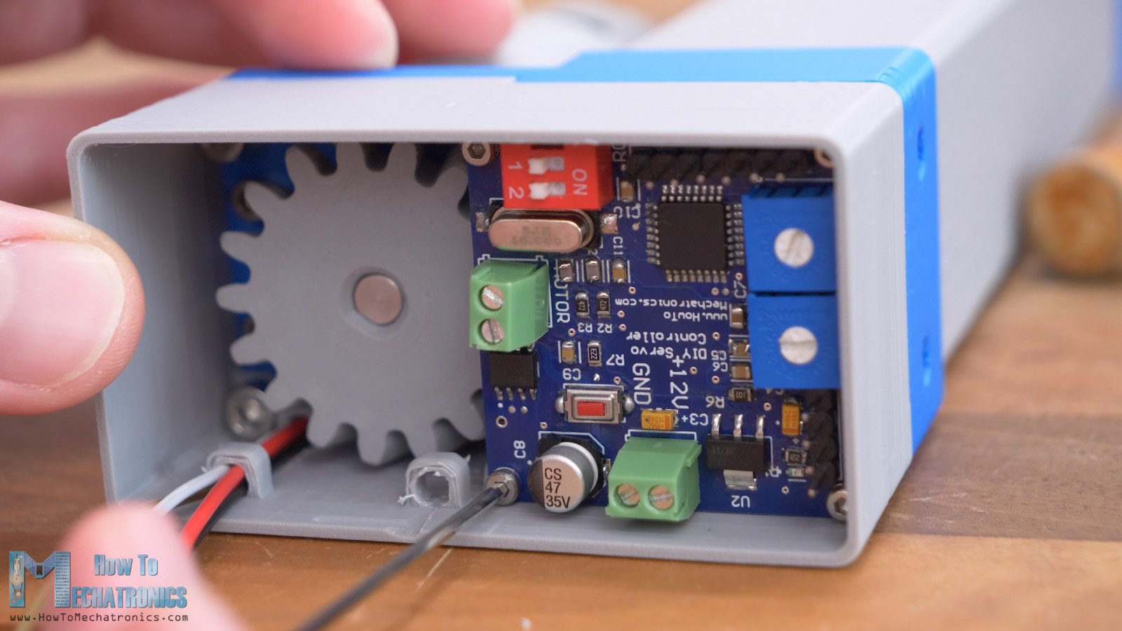
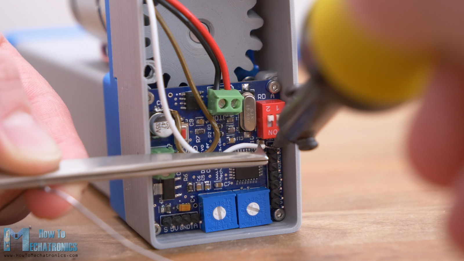
What’s left to do now is to connect the wires in place. The DC motor wires go to the motor terminal block, and the polarity should be checked additionally to match with the controller program.
Actually, before connecting the motor to the PCB, we can apply some voltage to it to check whether the lead screw mechanism works properly.
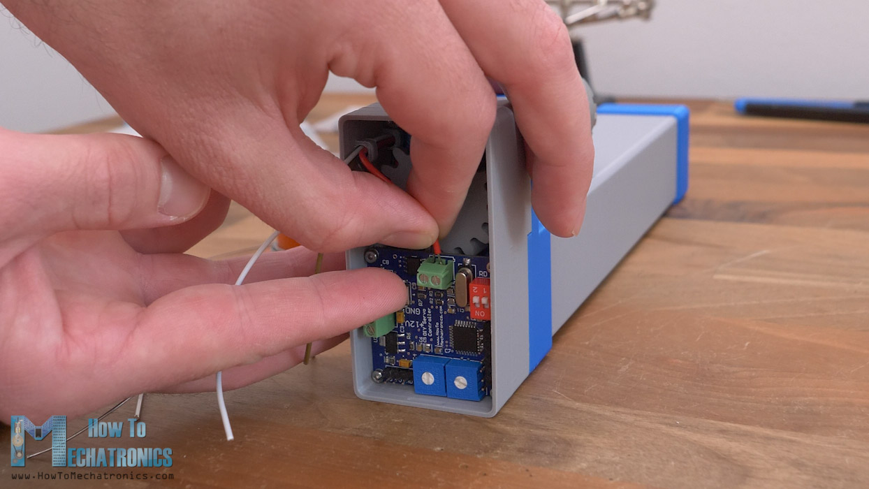
As for the limit switch wires, as I don’t have dedicated pins for this purpose, I soldered the ground wire to the ground pad on the electrolytic capacitor, and the NC connection wire to the SCK pin, which is digital pin number 13 on the ATMEGA328 micro controller.
The terminal block for the power is right next to the side of the cover, so there is a hole through which I connected a 5.5mm power connector.
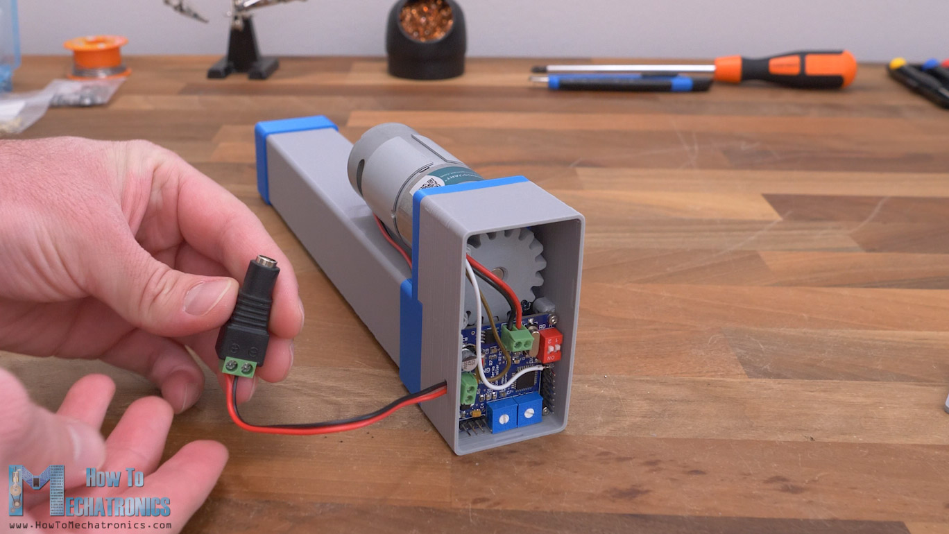
I also added a heat sink to the DC motor driver. Finally, we can put the snap-fit lid on the back side and that’s it, we are done with this project.
Now we can connect any type of potentiometer or an RC receiver to the appropriate input pins, and we can control the position of the linear actuator with it.
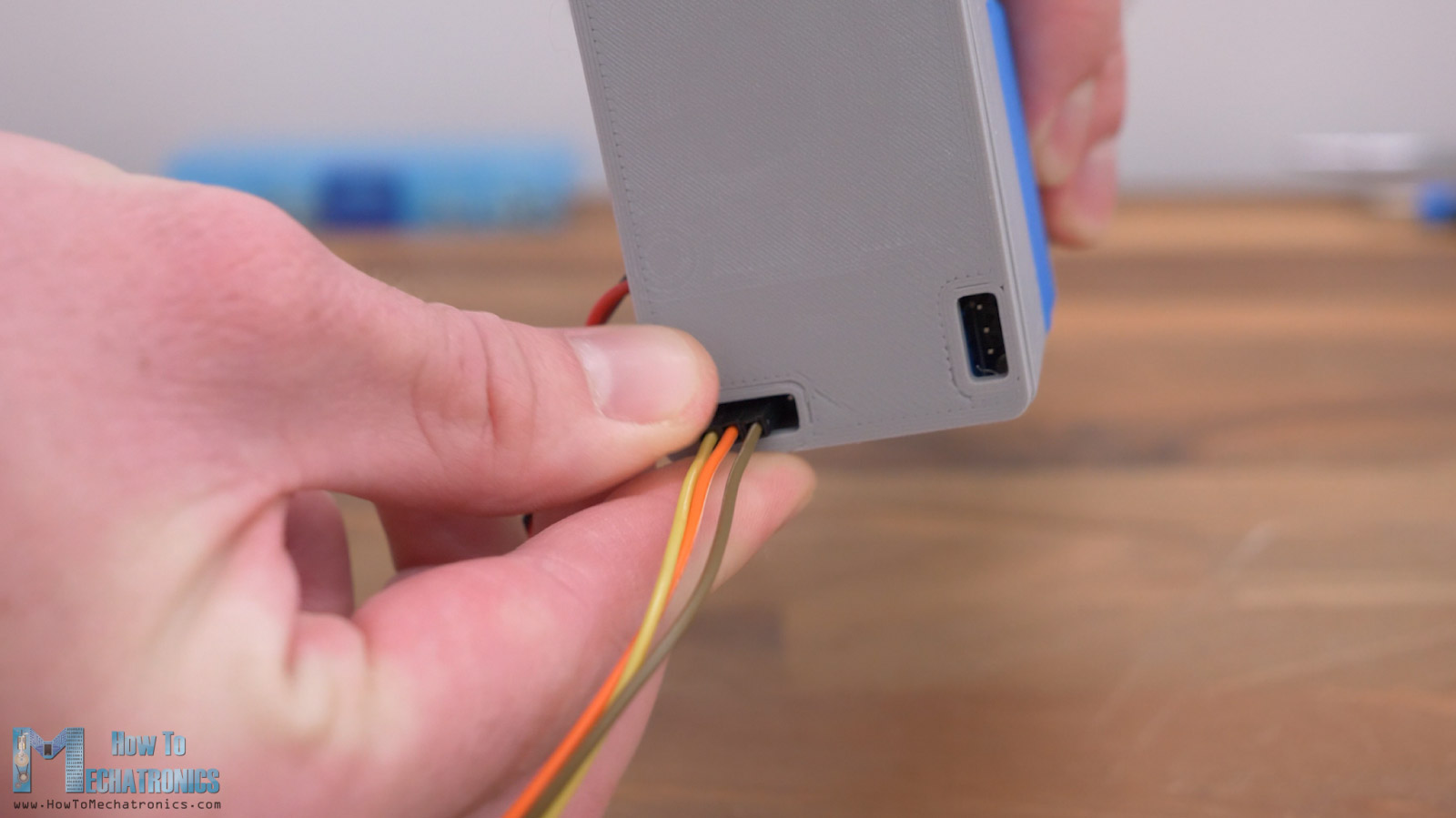
As I already mentioned, in my previous video I explained in detail how this controller works, its circuit schematic and how I made the PCB.
So, you should check that tutorial out if you want to make this controller board.
Circuit Schematic
Real quick, the main component is the AS5600 magnetic sensor, which keeps track of the position of actuator output. The sensor data goes into the brain of this servo controller board, the Atmega328 microcontroller, which does the math, and tells the DRV8871 DC motor driver how to drive the DC motor.
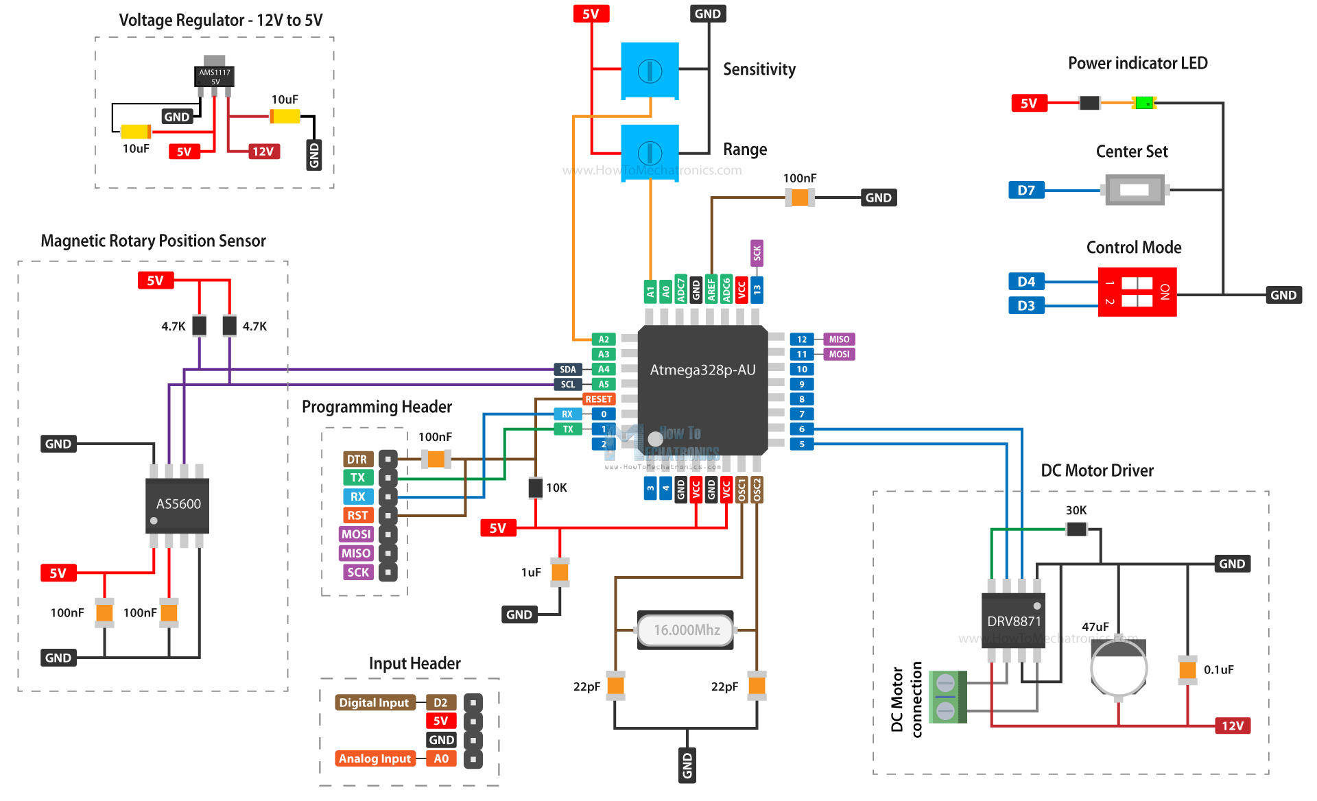
The DRV8871 DC motor driver can handle up to 3.6A of peak current. For powering the board, we can use 12V which is then dropped to 5V with an ASM1117 voltage regulator for the Atmega328 and the other 5V components. There is a two channel DIP switch through which we select the input mode of the actuator, either analog or digital, or via the serial port communication.
One of the trimmer potentiometers is used for adjusting the sensitivity of the actuator, and the SDM push button is used for setting the start and end positions.
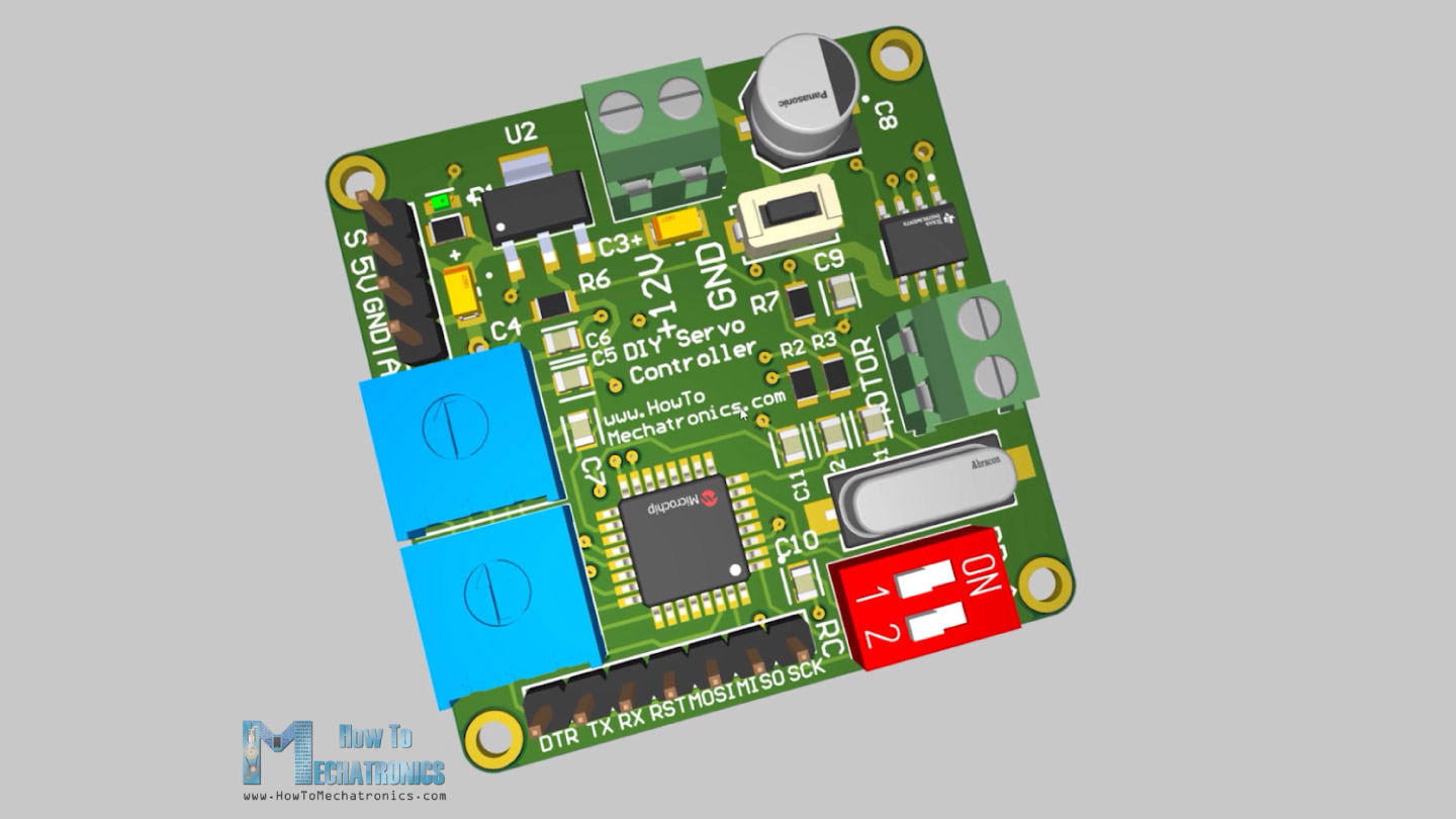
I ordered the PCB from PCBWay. Here we can simply upload the Gerber file, choose the properties of our PCB, and order it at a reasonable price.

I designed the PCB to have 4 layers, the middle ones are for GND, which increases the price a bit. I didn’t change any of the default properties except for the PCB color which I chose to be white, and I tick that I accept change for the Surface finish to Immersion gold if applicable without extra charge.
You can find and download the Gerber from the PCBWay projects sharing community through which you can also directly order the PCB.
Anyway, you can also make this linear actuator project even without this custom-built servo controller, of course.
You can use the AS5600 sensor on a breakout board in combination with an Arduino board for controlling the DC motor.
Code
Now let’s take a look at the code of this Linear Servo Actuator:
/*
      Linear Servo Actuator - Arduino Code
      by Dejan, www.HowToMechatronics.com

     Libraries:
     AS5600 encoder: https://github.com/RobTillaart/AS5600
     PID conroller: https://github.com/br3ttb/Arduino-PID-Library/blob/master/PID_v1.h
*/
#include "AS5600.h"
#include "Wire.h"
#include <PID_v1.h>

AS5600 as5600;  //  use default Wire

double Pk1 = 0.65;  //speed it gets there
double Ik1 = 0;
double Dk1 = 0.1;

//Define Variables we'll be connecting to
double Setpoint, Input, Output;

PID myPID(&Input, &Output, &Setpoint, Pk1, Ik1, Dk1, DIRECT);

#define motor_IN1 5
#define motor_IN2 6
#define ch1 2
#define setButton 7
#define inputSwitch 3
#define modeSwitch 4
#define limitSwitch 13

int ch1Value;

long encoderValue, desiredValue, pwmValue;
String serialInput = "";  // string to hold input
int serialIntInput;

double totalDistance = 0;
long startPosition = 358;
long endPosition = 6750;
long rangeAdjustment = 0;
float sensitivityAdjustment = 0;
float angle = 0;
float angleValue = 0;
float rodPosition;
float positionsArray[100];
int positionsCounter = 0;

long quadrantNumber = 2;
long previousQuadrantNumber = 3;
long numberOfTurns = 0;
float totalAngle = 0;

char incomingByte = 0;
int intInput = 0;

void setup() {
  Serial.begin(115200);
  Serial.println(__FILE__);
  Serial.print("AS5600_LIB_VERSION: ");
  Serial.println(AS5600_LIB_VERSION);

  Wire.begin();

  pinMode(motor_IN1, OUTPUT);
  pinMode(motor_IN2, OUTPUT);
  // Activate the Arduino internal pull-up resistors
  pinMode(setButton, INPUT_PULLUP);
  pinMode(inputSwitch, INPUT_PULLUP);
  pinMode(modeSwitch, INPUT_PULLUP);
  pinMode(limitSwitch, INPUT_PULLUP);

  // PID Setup
  myPID.SetMode(AUTOMATIC);
  myPID.SetOutputLimits(-255, 255);
  myPID.SetSampleTime(20);

  // --- HOMING ----
  // Move backward until you ...
  while (digitalRead(limitSwitch) != 1) {
    digitalWrite(motor_IN1, LOW);
    analogWrite(motor_IN2, 70);
    encoderValue = as5600.readAngle();
  }

  while (digitalRead(limitSwitch) != 0) {
    analogWrite(motor_IN1, 50);
    digitalWrite(motor_IN2, LOW);
  }
  digitalWrite(motor_IN1, LOW);
  digitalWrite(motor_IN2, LOW);
  startPosition = as5600.readAngle() * 0.087890625;
  endPosition = 6000;
  Setpoint = startPosition;
  // --- HOMING End ---
}

void loop() {

  // Read encoder value - current position
  rodPosition = as5600.readAngle() / 0.001953125;  // in millimters - The lead screw is 8mm per rotation, and the encoder RAW value is 4096 per roration, so 8/4096 to get the value in milimiters

  // Serial communication mode - Read data from the serial monitor
  if (digitalRead(modeSwitch) == 0) {
    while (Serial.available() > 0) {
      serialInput = Serial.readString();
      serialInput.trim();
      // If "save" string is sent through the serial monitor, save the current rodPosition into the array
      if (serialInput == "save") {
        positionsArray[positionsCounter] = totalDistance;
        delay(1000);
        positionsCounter++;
      }
      // Clear the saved positions
      if (serialInput == "clear") {
        // Clear the array data to 0
        memset(positionsArray, 0, sizeof(positionsArray));
        positionsCounter = 0;
      }
      // Convert the String to Integer and use it as a Setpoint for the PID control
      serialIntInput = serialInput.toInt();
      if (serialIntInput != 0) {
        if (serialIntInput < 0) {
          serialIntInput = 0;
        }
        if (serialIntInput > 150) {
          serialIntInput = 150;
        }
        Setpoint = serialIntInput * 45; // convert mm into degrees (1mm linear movement equals 45 degrees rotational movement)
      }
    }

    // Run stored positions
    if (serialInput == "run") {
      while (serialInput != "stop") {
        for (int i = 0; i <= positionsCounter - 1; i++) {
          if (serialInput == "stop") {
            break;
          }

          while (positionsArray[i] > totalDistance + 25 || positionsArray[i] < totalDistance - 25 || pwmValue != 0) {
            // Desired position / setpoint for the PID contorller
            Setpoint = positionsArray[i];
            // Read encoder - use that value as an Input for the PID control
            readEncoder();
            // Run motor - PID controller inside
            runMotor();

          }

          delay(2000); // Delay between steps
          // Check the serial monitor for a stop command
          while (Serial.available() > 0) {
            serialInput = Serial.readString();
            serialInput.trim();
          }
        }
      }
    }
  }
  // Potentiometer and RC Receiver control mode
  else if (digitalRead(modeSwitch) == 1) {

    if (digitalRead(inputSwitch) == 0) {  // Analog input - Potentiometer
      // Get value from potentiometer
      desiredValue = analogRead(A0);
      if (desiredValue < 15) {
        desiredValue = 15;
      }
      if (desiredValue > 1008) {
        desiredValue = 1008;
      }
      Setpoint = map(desiredValue, 15, 1008, startPosition, endPosition);

    } else if (digitalRead(inputSwitch) == 1) {  // Digital input - RC transmitter
      desiredValue = pulseIn(ch1, HIGH, 30000);  // Read RC receiver as input

      if (desiredValue < 1000 || desiredValue > 2000) {
        desiredValue = 1000;
      }
      Setpoint = map(desiredValue, 1000, 2000, startPosition, endPosition);
    }
  }

  // Confine the minimum and maximum values of the setpoint
  if (Setpoint > endPosition) {
    Setpoint = endPosition;
  }
  if (Setpoint < startPosition) {
    Setpoint = startPosition;
  }
  // Adjusting sensitivity
  //Pk1 = analogRead(A2) * 0.002; // Adjust the PID gain term
  //myPID.SetTunings(Pk1, Ik1, Dk1);
  // Read encoder - use that value as an input for the PID control
  readEncoder();
  // Run motor
  runMotor();

  // Set start and end positions by pressing the "set" button
  if (digitalRead(setButton) == LOW) {
    delay(3000);
    if (digitalRead(setButton) == LOW) {
      endPosition = totalDistance;
      while (digitalRead(setButton) != HIGH)
        ;
    } else {
      startPosition = totalDistance;
    }
  }
}

void readEncoder() {
  // Convert encoder RAW values into angle values for keeping track of the angular position of the shaft
  encoderValue = as5600.readAngle() * 0.087890625;

  // Quadrant 1
  if (encoderValue >= 0 && encoderValue <= 90) {
    quadrantNumber = 1;
  }
  // Quadrant 2
  if (encoderValue >= 90 && encoderValue <= 180) {
    quadrantNumber = 2;
  }
  // Quadrant 3
  if (encoderValue >= 180 && encoderValue <= 270) {
    quadrantNumber = 3;
  }
  // Quadrant 4
  if (encoderValue >= 270 && encoderValue <= 360) {
    quadrantNumber = 4;
  }

  if (quadrantNumber != previousQuadrantNumber) {
    // Transition from 4th to 1st quadrant
    if (quadrantNumber == 1 && previousQuadrantNumber == 4) {
      numberOfTurns++;
    }
    // Transition from 1st to 4th quadrant
    if (quadrantNumber == 4 && previousQuadrantNumber == 1) {
      numberOfTurns--;
    }
    previousQuadrantNumber = quadrantNumber;
  }
  if (totalDistance >= 0) {
    totalDistance = (numberOfTurns * 360) + encoderValue;
  } else {
    totalDistance = (numberOfTurns * 360) + encoderValue;
  }
  // Establish Input value for PID
  Input = totalDistance;  // current value of the position
}

void runMotor() {
  // Run PID process to get Output value
  myPID.Compute();

  // Move right
  if (Output > 1) {
    pwmValue = Output;

    if (pwmValue < 50 && pwmValue > 15) {
      pwmValue = pwmValue + 40;
    }
    if (pwmValue <= 15) {
      pwmValue = 0;
    }
    analogWrite(motor_IN1, pwmValue);
    digitalWrite(motor_IN2, LOW);
  }
  // Move left
  else if (Output < 1) {
    pwmValue = abs(Output);

    if (pwmValue < 50 && pwmValue > 15) {
      pwmValue = pwmValue + 40;
    }
    if (pwmValue <= 15) {
      pwmValue = 0;
    }
    digitalWrite(motor_IN1, LOW);
    analogWrite(motor_IN2, pwmValue);
  }
  // Do not move
  else if (Output > -1 && Output < 1) {
    pwmValue = 0;
    digitalWrite(motor_IN1, LOW);
    digitalWrite(motor_IN2, LOW);
  }
}
Code language: PHP (php)
Code Description
So, we start the loop by reading the encoder value or the current position of the actuator and convert it into millimeters.
// Read encoder value - current position
  rodPosition = as5600.readAngle() / 0.001953125;  // in millimters - The lead screw is 8mm per rotation, and the encoder RAW value is 4096 per roration, so 8/4096 to get the value in milimiters
Code language: PHP (php)
Then if we are in the “Serial communication mode” we read the incoming data that we enter on the Serial monitor. If the input is “save” we store the current position actuator, or if it’s “clear” we clear all already stored positions.
// Serial communication mode - Read data from the serial monitor
  if (digitalRead(modeSwitch) == 0) {
    while (Serial.available() > 0) {
      serialInput = Serial.readString();
      serialInput.trim();
      // If "save" string is sent through the serial monitor, save the current rodPosition into the array
      if (serialInput == "save") {
        positionsArray[positionsCounter] = totalDistance;
        delay(1000);
        positionsCounter++;
      }
      // Clear the saved positions
      if (serialInput == "clear") {
        // Clear the array data to 0
        memset(positionsArray, 0, sizeof(positionsArray));
        positionsCounter = 0;
      }Code language: JavaScript (javascript)
If the input is integer or a number, from 0 to 150, we use that value as a setpoint.
// Convert the String to Integer and use it as a Setpoint for the PID control
      serialIntInput = serialInput.toInt();
      if (serialIntInput != 0) {
        if (serialIntInput < 0) {
          serialIntInput = 0;
        }
        if (serialIntInput > 150) {
          serialIntInput = 150;
        }
        Setpoint = serialIntInput * 45; // convert mm into degrees (1mm linear movement equals 45 degrees rotational movement)
      }
    }Code language: JavaScript (javascript)
We enter the values in millimeters, but for keeping track of the rotating shaft, we are using degrees, so therefore we convert the millimeters values into degrees values by multiplying by 45. That’s so because for 1mm linear movement, the lead screw should rotate 45 degrees. In case you have different pitch on your lead screw, this number should be different.
If we type “run”, with the help of some while and for loops, the program will run through the stored positions repeatedly.
// Run stored positions
    if (serialInput == "run") {
      while (serialInput != "stop") {
        for (int i = 0; i <= positionsCounter - 1; i++) {
          if (serialInput == "stop") {
            break;
          }

          while (positionsArray[i] > totalDistance + 25 || positionsArray[i] < totalDistance - 25 || pwmValue != 0) {
            // Desired position / setpoint for the PID contorller
            Setpoint = positionsArray[i];
            // Read encoder - use that value as an Input for the PID control
            readEncoder();
            // Run motor - PID controller inside
            runMotor();

          }

          delay(2000); // Delay between steps
          // Check the serial monitor for a stop command
          while (Serial.available() > 0) {
            serialInput = Serial.readString();
            serialInput.trim();
          }
        }
      }
    }Code language: JavaScript (javascript)
On the other hand, if we are in the Potentiometer and RC receiver control mode, we check whether we have analog or digital input.
// Potentiometer and RC Receiver control mode
  else if (digitalRead(modeSwitch) == 1) {

    if (digitalRead(inputSwitch) == 0) {  // Analog input - Potentiometer
      // Get value from potentiometer
      desiredValue = analogRead(A0);
      if (desiredValue < 15) {
        desiredValue = 15;
      }
      if (desiredValue > 1008) {
        desiredValue = 1008;
      }
      Setpoint = map(desiredValue, 15, 1008, startPosition, endPosition);

    } else if (digitalRead(inputSwitch) == 1) {  // Digital input - RC transmitter
      desiredValue = pulseIn(ch1, HIGH, 30000);  // Read RC receiver as input

      if (desiredValue < 1000 || desiredValue > 2000) {
        desiredValue = 1000;
      }
      Setpoint = map(desiredValue, 1000, 2000, startPosition, endPosition);
    }
  }Code language: JavaScript (javascript)
If analog, we read the analog input from the potentiometer and use that value as a Setpoint, or desired position for the actuator to go to. Similarly, if the input is digital, we read the incoming data from the RC receiver and use that value as a setpoint.
Then we call the readEncoder() and runMotor() custom functions to read the current position of the actuator and execute the PID control. With the readEncoder() function we read the current value of the sensor in angle values, and with these if statements we keep track in which quadrant the current position of the shaft is.
void readEncoder() {
  // Convert encoder RAW values into angle values for keeping track of the angular position of the shaft
  encoderValue = as5600.readAngle() * 0.087890625;

  // Quadrant 1
  if (encoderValue >= 0 && encoderValue <= 90) {
    quadrantNumber = 1;
  }
  // Quadrant 2
  if (encoderValue >= 90 && encoderValue <= 180) {
    quadrantNumber = 2;
  }
  // Quadrant 3
  if (encoderValue >= 180 && encoderValue <= 270) {
    quadrantNumber = 3;
  }
  // Quadrant 4
  if (encoderValue >= 270 && encoderValue <= 360) {
    quadrantNumber = 4;
  }

  if (quadrantNumber != previousQuadrantNumber) {
    // Transition from 4th to 1st quadrant
    if (quadrantNumber == 1 && previousQuadrantNumber == 4) {
      numberOfTurns++;
    }
    // Transition from 1st to 4th quadrant
    if (quadrantNumber == 4 && previousQuadrantNumber == 1) {
      numberOfTurns--;
    }
    previousQuadrantNumber = quadrantNumber;
  }
  if (totalDistance >= 0) {
    totalDistance = (numberOfTurns * 360) + encoderValue;
  } else {
    totalDistance = (numberOfTurns * 360) + encoderValue;
  }
  // Establish Input value for PID
  Input = totalDistance;  // current value of the position
}Code language: HTML, XML (xml)
With this information, we can keep track of how the shaft rotates and when it will make a full turn. The total angle is the Input value for the PID controller.
Using the analog input from the trimmer potentiometer we can adjust the proportional gain of the PID controller, and finally we run the PID process to get an output value.
// Adjusting sensitivity
  //Pk1 = analogRead(A2) * 0.002; // Adjust the PID gain term
  //myPID.SetTunings(Pk1, Ik1, Dk1);Code language: JSON / JSON with Comments (json)
void runMotor() {
// Run PID process to get Output value
myPID.Compute();
// Move right
if (Output > 1) {
pwmValue = Output;
if (pwmValue < 50 && pwmValue > 15) {
pwmValue = pwmValue + 40;
}
if (pwmValue <= 15) {
pwmValue = 0;
}
analogWrite(motor_IN1, pwmValue);
digitalWrite(motor_IN2, LOW);
}
// Move left
else if (Output < 1) {
pwmValue = abs(Output);
if (pwmValue < 50 && pwmValue > 15) {
pwmValue = pwmValue + 40;
}
if (pwmValue <= 15) {
pwmValue = 0;
}
digitalWrite(motor_IN1, LOW);
analogWrite(motor_IN2, pwmValue);
}
// Do not move
else if (Output > -1 && Output < 1) {
pwmValue = 0;
digitalWrite(motor_IN1, LOW);
digitalWrite(motor_IN2, LOW);
}
}Code language: JavaScript (javascript)We use that output value for driving the DC motors with PWM signal, left or right, or in still position depending on the output value from the PID controller, or depending on the error between the desired and the actual position the encoder reads.
The three terms of the PID controller, the proportional, integral and derivative are defined at the top, and by adjusting them we can get various output responses.
double Pk1 = 0.65;  //speed it gets there
double Ik1 = 0;
double Dk1 = 0.1;Code language: JavaScript (javascript)
The quality, how well the actuator will work or respond to our inputs directly depends on these values.
Testing
Here I’m testing the actuator accuracy. It gets back in place decently. Then a started to move the rod one millimeter at a time. The first movement was like 0.8mm instead of 1mm, but the next 4 were close enough to 1mm. Then the 4mm movement was about 0.15mm off.
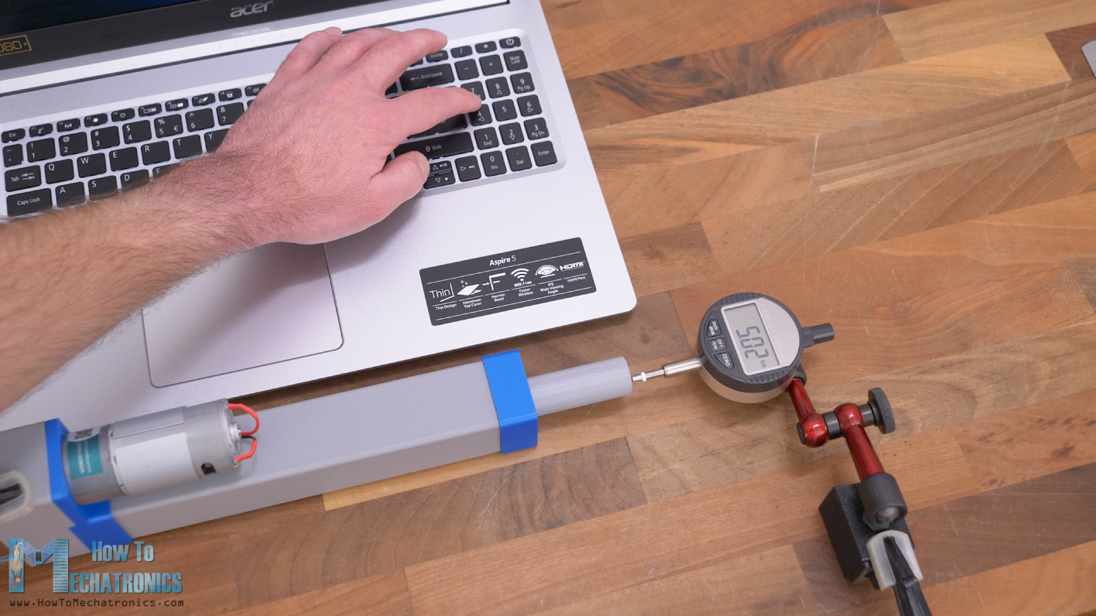
We should notice that rod has a backlash of around 0.25mm. This backlash is between the lead screw and the leadscrew nut. In addition to that we have probably some backlash in the 3D printed gears as well as the gears of the DC motor itself.
If we apply a force to the rod and test the accuracy now, of course, we will get even greater error, but this can be improved by tweaking the PID controller.
Nevertheless, that would be all for this tutorial. I hope you enjoyed it and learned something new.