In this tutorial I will show you how I built an Arduino based 3D wire bending machine. This is actually a typical mechatronic system because it involves mechanical, electrical and computer engineering. So therefore I believe many engineering students or anyone who is new into mechatronics found this project interesting.
You can watch the following video or read the written tutorial below.
Overview
Here’s the working principle of this 3D wire bending machine. So first, the wire goes through a series rollers, or straighteners. Using a stepper motor the wire is precisely fed to the wire bending mechanism which also uses a stepper motor as well as a small servo for the bending process.
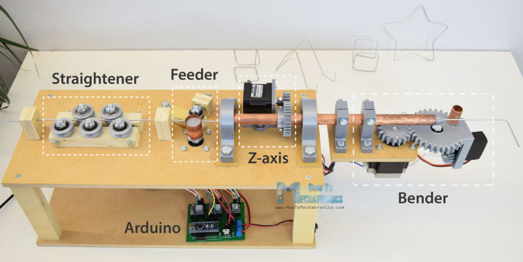
There’s also another stepper motor, called the Z-axis, which actually enables the machine to create three dimensional forms. Of course, the brain of the machine is an Arduino board which along with the other electronics components is attached on a custom designed PCB.
As for the program, I made few custom functions for making various shapes, like a star, a cube and a simple stand, as well as a manual mode where we can make the wire forms by entering commands through the serial monitor.
DIY 3D Wire Bending Machine 3D Model
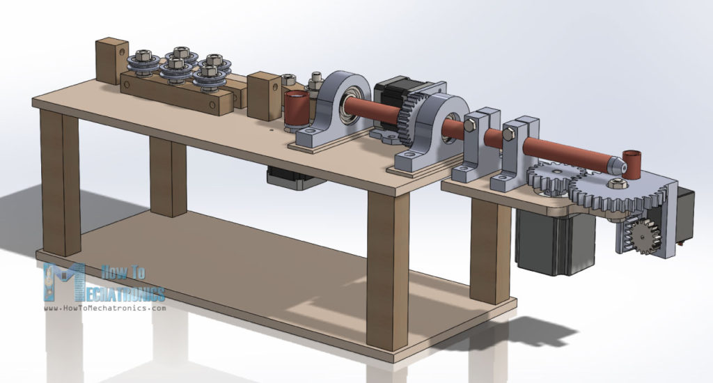
As usual, I started by making the project using a 3D modeling software. You can download and the 3D model below.
Design inspiration: YouTube video
You can find and download this 3D model, as well as explore it in your browser on Thangs.
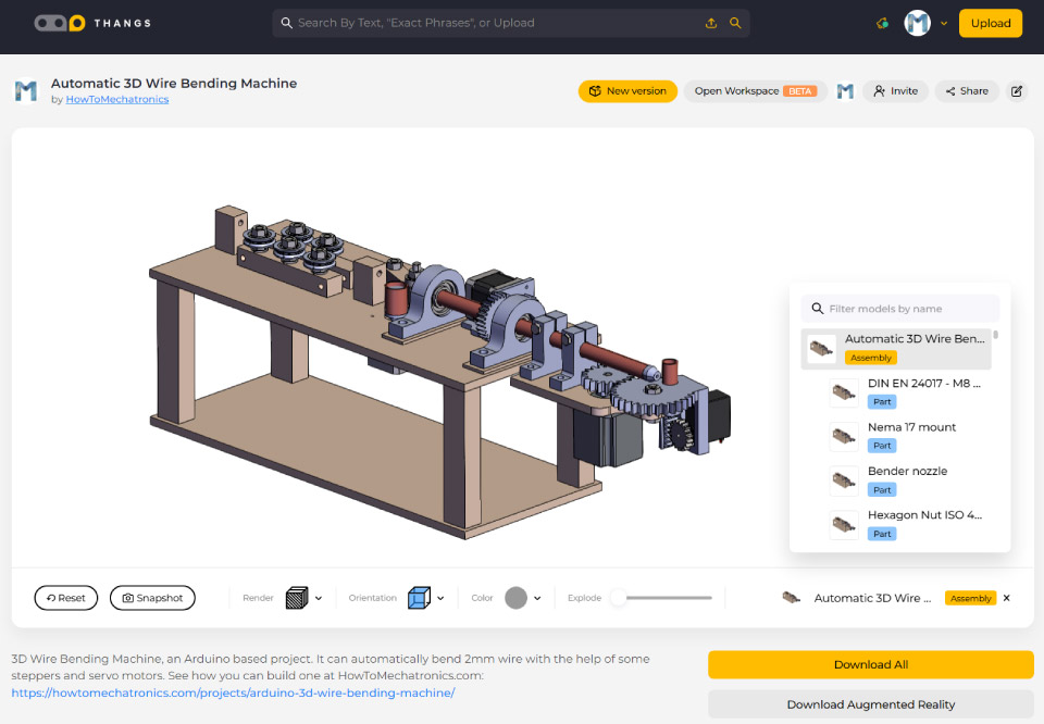
You can download the assembly 3D model at Thangs.
STL files for 3D Printing:
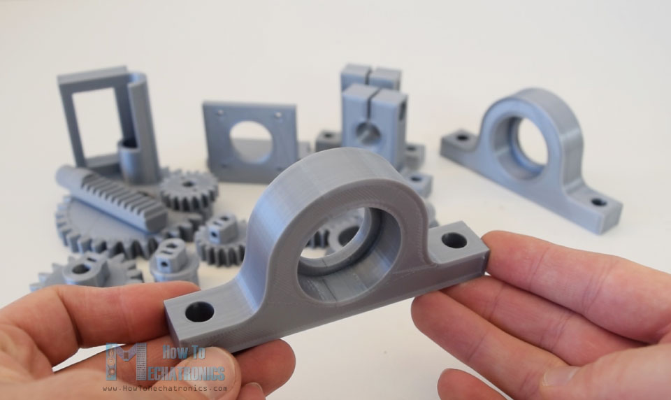
For some of the parts, like the gears, the bearing pillow blocks and some shaft couplers I used a 3D printer to make them. The STL files of these parts, which are used for 3D printing, can be downloaded from the files above.
My new 3D printer, Creality CR-10, did a great job and printed the parts with great quality. Here’s a link to this 3D printer in case you want to check it out.
Building the Wire Bending Machine
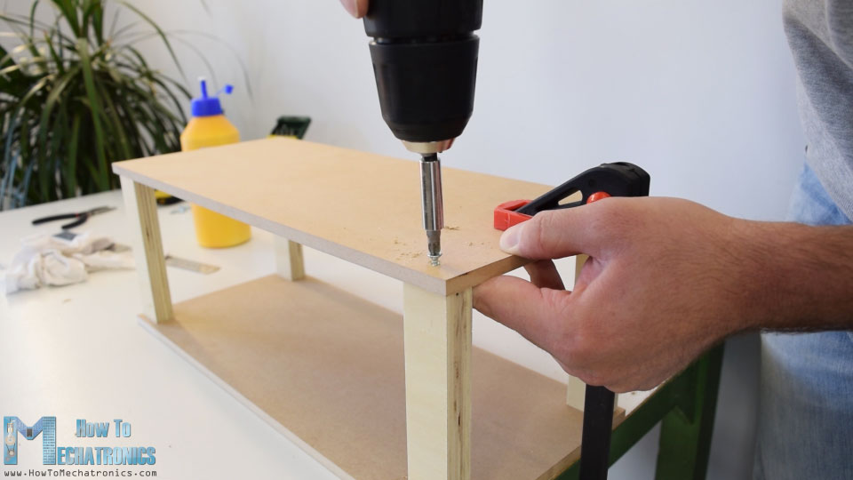
I continued with preparing the other parts, for which I used MDF and plywood. So once I took all dimensions from the 3D model, using a circular saw, I cut the pieces to size. I used 8 mm tick MDF and 18 mm tick plywood. Once I got them ready I started with the assembly. First I made the base out of two MDF plates and 4 plywood columns. For securing them I used a wood glue and some screws.
Next on the top panel I attached the 3D printed bearing pillow blocks using some 8 mm bolts and nuts. We can notice here that I added 3 mm tick MDF plates between the top and the pillow blocks so that I get the proper height. Now in these blocks we can fit the 6202 bearings.
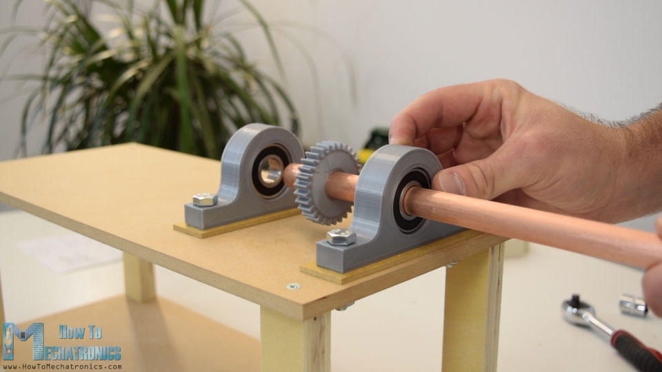
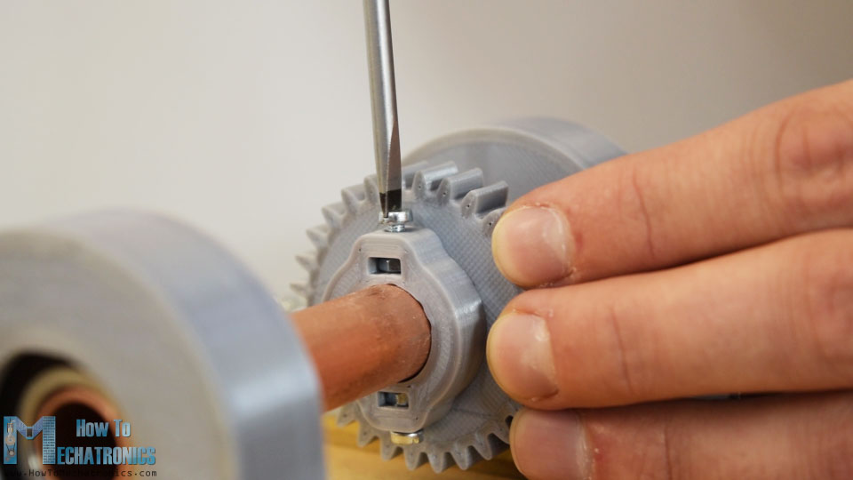
Their outer diameter is 35 mm and the inner diameter is 15 mm. So now, through these bearings, we need to insert a 15 mm hollow shaft so that the wire could pass through it. This shaft is actually the Z-axis, which enables to bending mechanism to rotate around the wire and in that way make three dimensional forms. I used a copper tube for that purpose and its length needs to be around 30 cm.
In between the two bearings I also inserted a 3D printed gear with module of 1.5 and 30 teeth. The gear has custom design slots where we can insert M3 nuts and then using M3 bolts we can tighten the gear to the shaft.
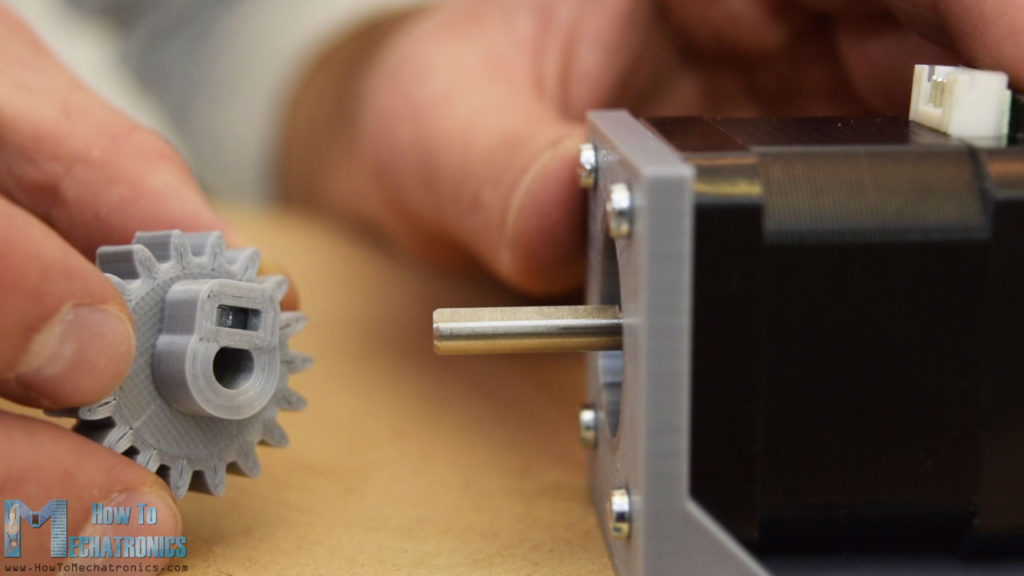
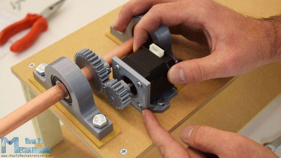
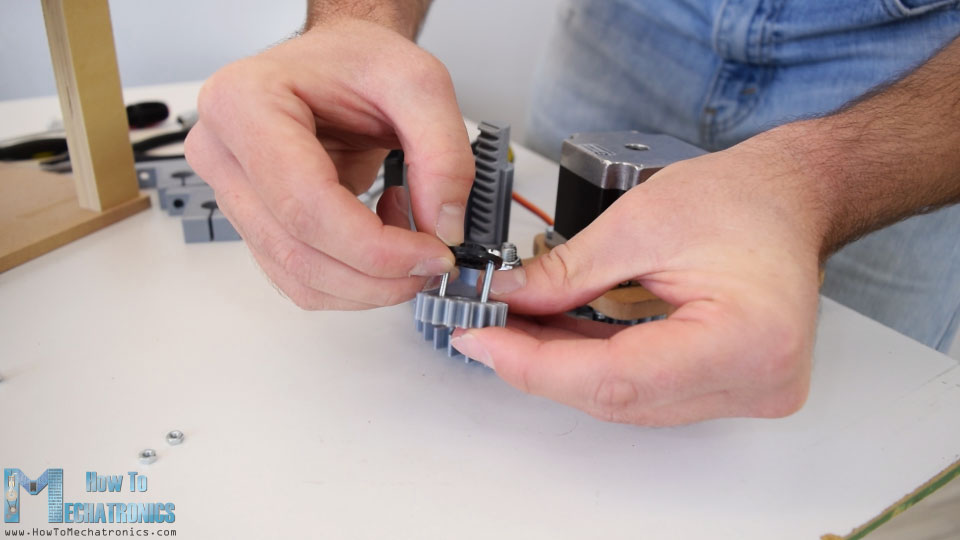
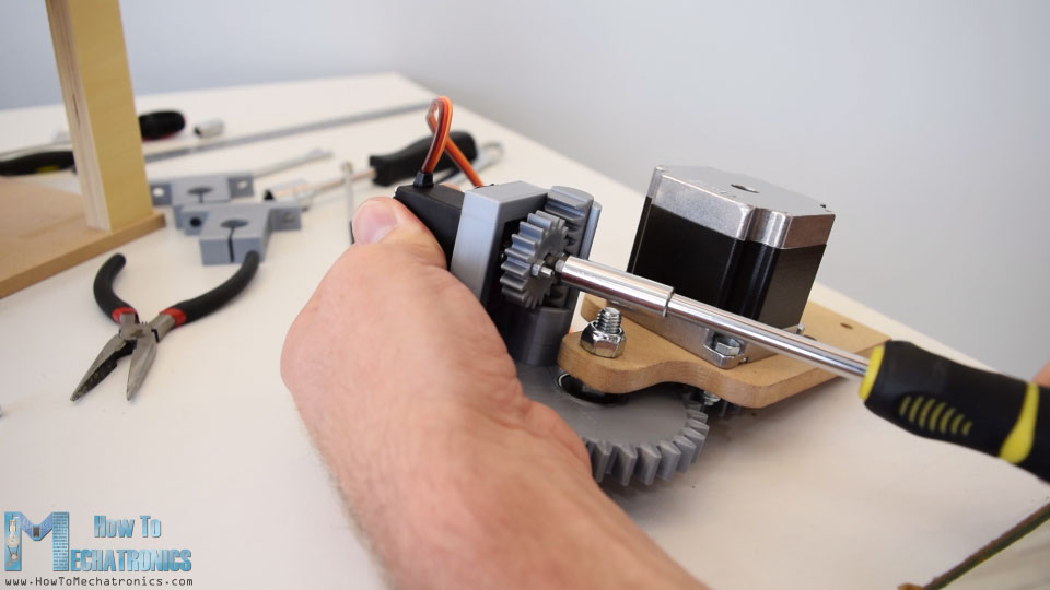
Next we need install the Z-axis stepper motor. For that purpose I 3D printed a custom mounting bracket. So I secured the stepper to the bracket using M3 bolts, and then inserted the 18 teeth gear on the motors shaft. I used the same method for securing the gear to the shaft as shown earlier.
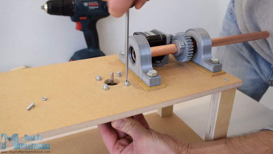
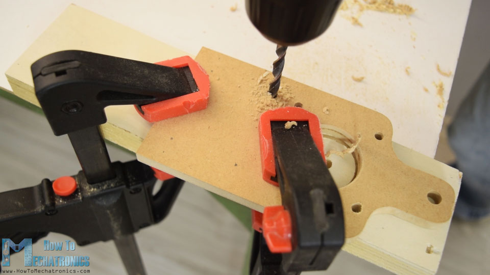
Then using a 6 mm drill I made two holes on the top on which the mounting bracket will be secured. We can notice that the bracket instead of holes, has slots which enables the two gears to be properly paired.
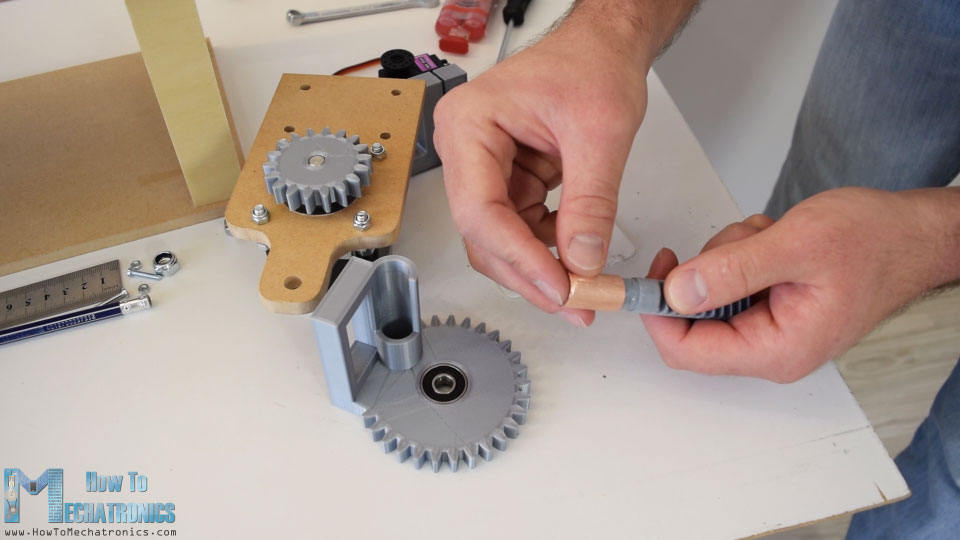
I moved on with installing the stepper motor for the feeder mechanism. This motor will be directly mounted on the top plate, so I drilled the appropriate holes on it. Then using four bolts I secured the stepper to the plate, and in case you wonder what those nuts do here, they actually act as distance nuts because the bolts I had were longer and couldn’t fit into the motors threads.
So now on the shaft of this stepper we need to insert the feeder. For that purpose I 3D printed a custom shaft coupler on which I inserted a copper tube which will actually be the contact surface of the feeder.
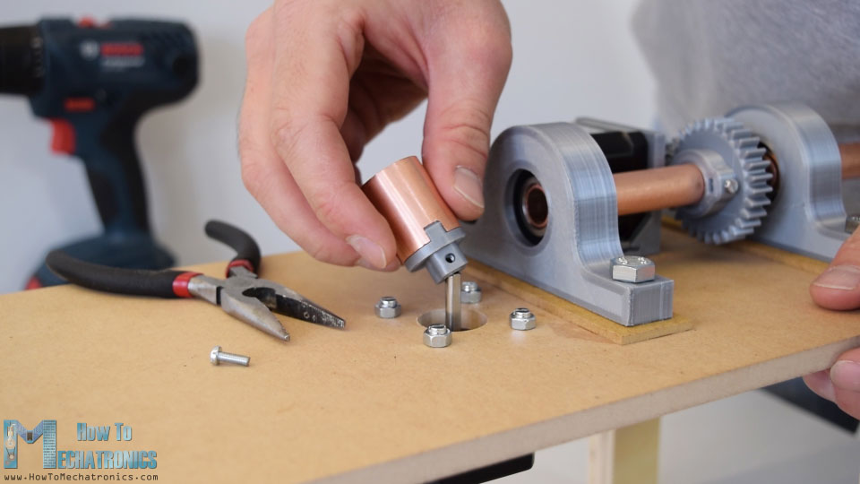
Then on the opposite side of the motor I inserted a lever, on which I attached a bearing which will press against the feeder. For getting enough grip so the feeder could move the wire, I will attach a piece of plywood with a T-nut on it, and then using a bolt we will be able control the grip of the feeder.
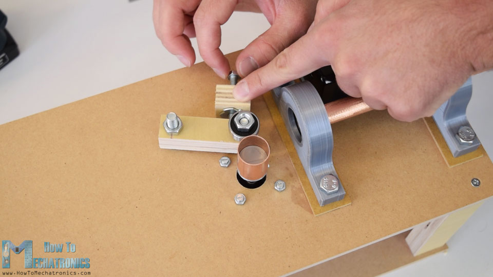
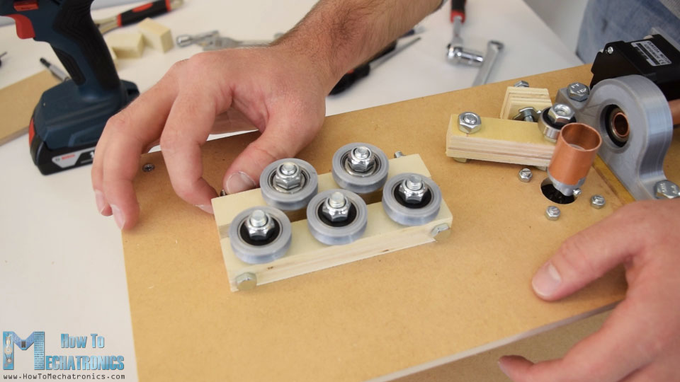
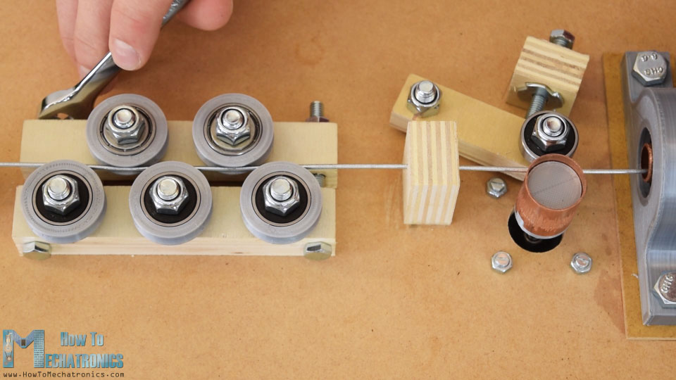
The next step is making the wire straightening system. Using three M8 bolts I secured a piece of plywood that I previously drilled according to the 3D model. Now on top of it I inserted the rollers. I made the rollers out of bearings and 3D printed grooved outer rings.
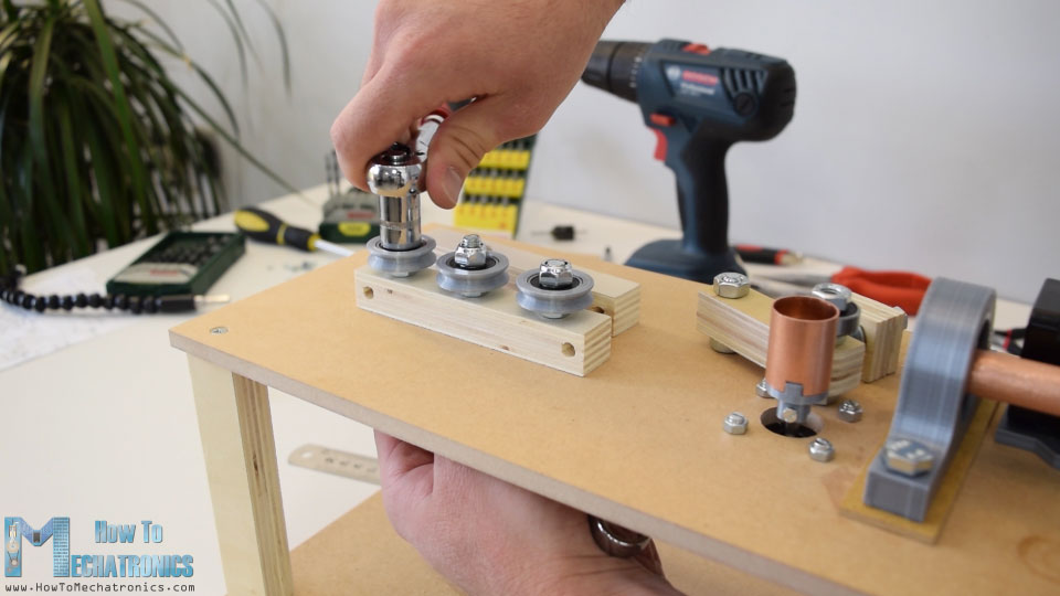
Three rollers go on this side, and two rollers on the other side. For the other side I made a slot in the plywood piece so that the bolts stay flush with the piece. Now using just two bolts we can pair the two side, and using the nuts we can tighten the straighteners appropriately.
Once finished with this step, I added two more pieces of plywood in front and after the straighteners which will serve as wire guides.
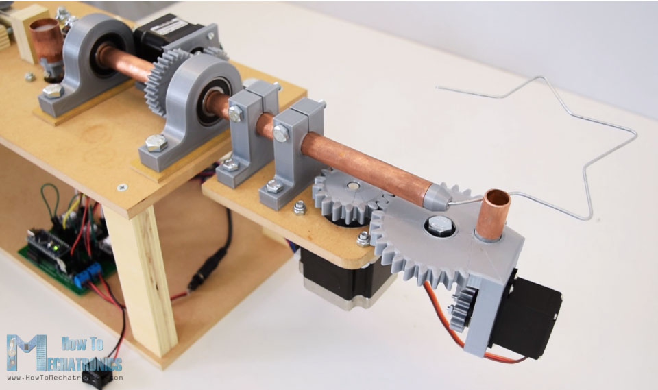
Ok, so now we can move on with making the wire bending mechanism. First on a piece of MDF we need to attach the bender motor. Before I did that, the MDF piece that I had needed some shaping, so using a handsaw, a coping saw and a rasp I easily got the desired shape. Then using a 38 mm hole saw I made an opening for the bigger stepper that we will use for the bending, a NEMA 23 stepper motor. Also I drilled some smaller holes needed for attaching the other parts.
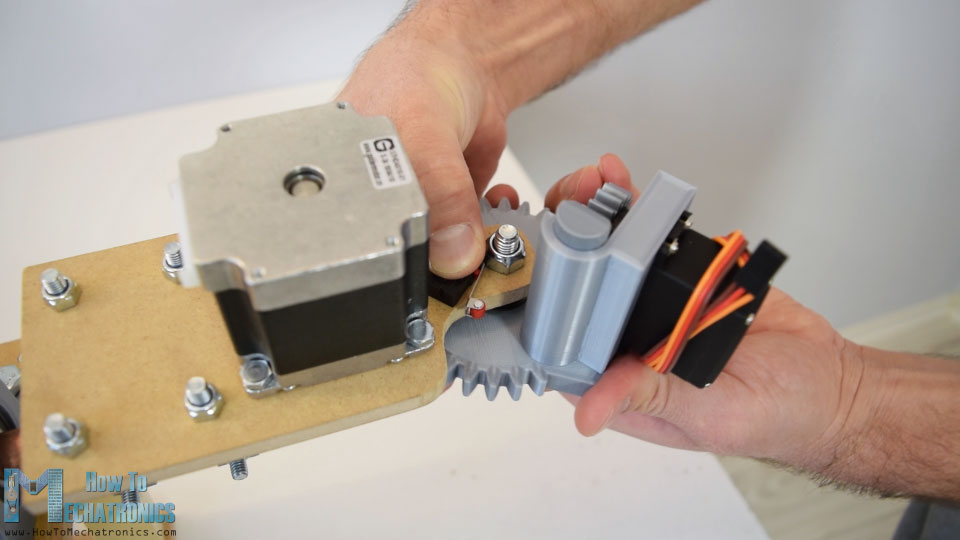
I secured the NEMA 23 stepper using M4 bolts and nuts and on its output shaft I attached a gear with module of 2.5 and 18 teeth. This gear will be paired with bigger 30 teeth gear which is a custom designed gear with integrated plate for mounting a MG996R servo. This servo will move a rack and pinion mechanism, which is actually a pin which will pop out of the gear and it will serve for bending the wire. Using a 5 minutes epoxy I secured a bearing onto the gear and also added a piece of copper tube onto the rack which will be the contact surface when bending the wire.
After the epoxy dried out, I paired the two gears by securing the bigger gear in place with a M8 bolt and a nuts. Then I inserted the rack and the servo in placed, and secured it using the screws provided in the servos package. Then I secured the pinion gear onto the round horn of the servo using two M3 bolts and nuts.
Finally I attached the horn to the servo and with this the bending mechanism was completed.
What’s left to do now is to attach the bender to the Z-axis. I did that using the two 3D printed shaft clamps. First I secured them to the bender plate using M6 bolts and nuts, and then inserted them into the Z-axis. I inserted the two nuts in place, and using the bolts I tightened the clamps to the shaft. So now all moving parts are working properly.
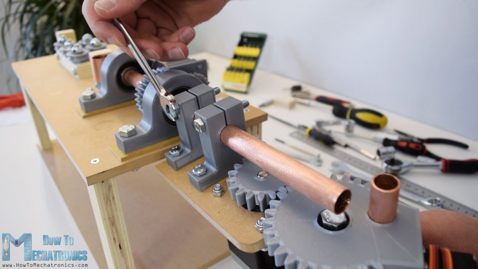
Actually there are two more small details to be added. That’s this 3 mm nozzle on the shaft where the wire comes out.
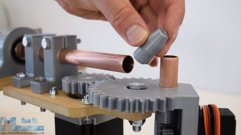
And at the bottom of bender I placed a micro limit switch which will be used for setting initial position of the bender.
And that’s it, our 3D wire bending machine is almost done. I say almost, because now we need to give live to this machine, or connect the electronics components and program it.
Circuit Diagram
Here’s the circuit diagram of this project.
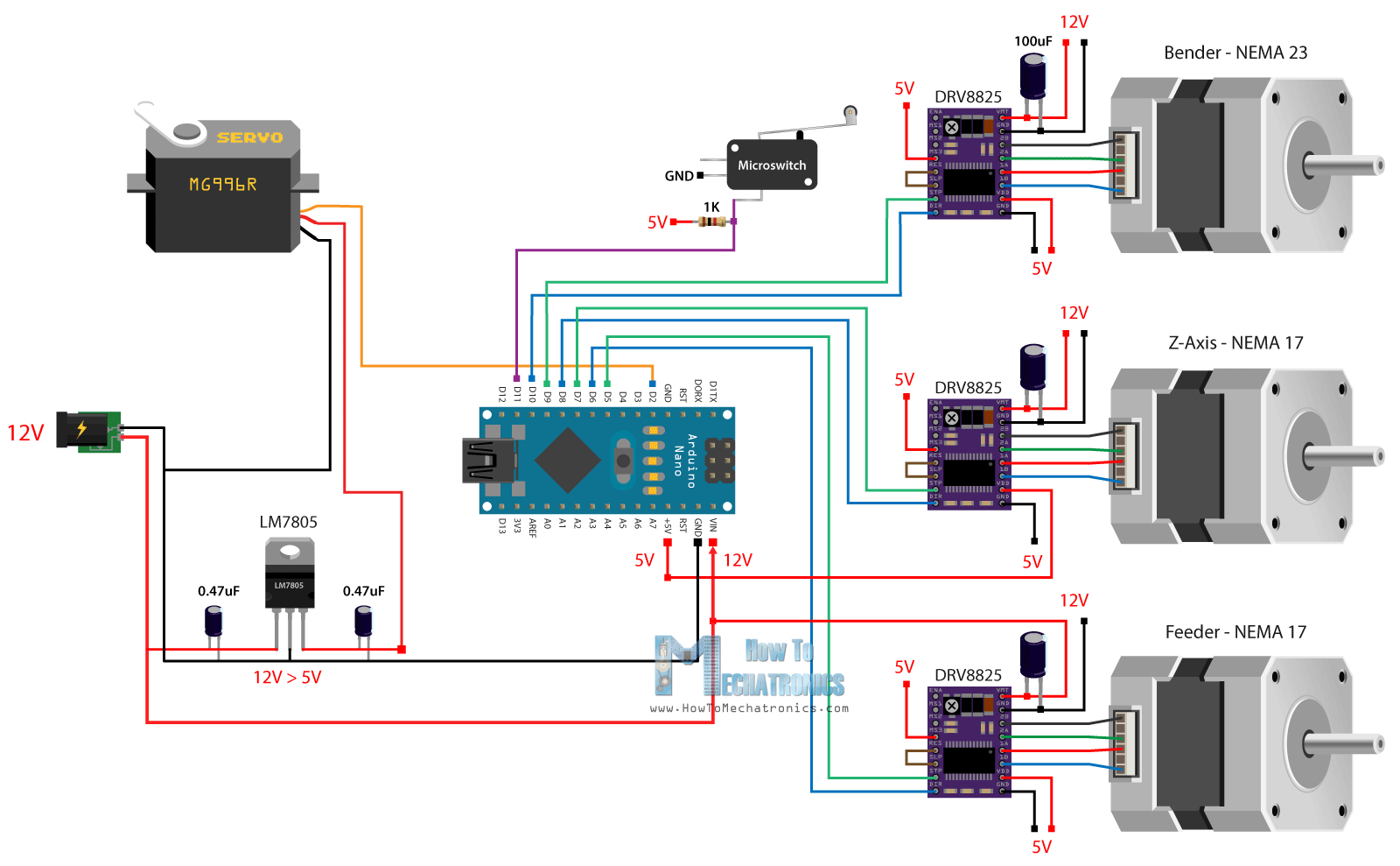
So the three stepper motors are controlled using the three DRV8825 stepper drivers. For powering the steppers and the whole project we will use 12V power supply with at least 3A of current rate.
For powering the servo, we could use the 5V coming from the Arduino, but the MG996R servo can be power hungry and the 5V voltage regulator of the Arduino might not be able to handle it. Therefore, I decided to use a separate 5V voltage regulator, the LM7805, which is good enough to power the servo for this project. There is also a limit switch for the bender which has a pull up resistor it’s connected to a digital pin of the Arduino board.
You can get the components needed for this project from the links below:
- Stepper Motor – NEMA 17……… Amazon / Banggood / AliExpress
- Stepper Motor – NEMA 23 …….. Amazon / Banggood / AliExpress
- DRV8825 Stepper Driver…….…. Amazon / Banggood / AliExpress
- Micro Limit Switch ………..……… Amazon / Banggood / AliExpress
- 12V 2A Adapter…………………..…. Amazon / Banggood / AliExpress
- Power Jack…………….………….…… Amazon / Banggood / AliExpress
- Arduino Board ……………………… Amazon / Banggood / AliExpress
Disclosure: These are affiliate links. As an Amazon Associate I earn from qualifying purchases.
PCB Design
Next, in order to get rid of wiring mess and keep the electronics components organize I designed a custom PCB using the EasyEDA free online circuit design software. The circuit has many connection, so I used both the top and the bottom layers to organize them. I also added pins for selecting the steppers resolution, added one more limit switch connection and provided additional digital and analog pins coming from the Arduino in case we need them for something.
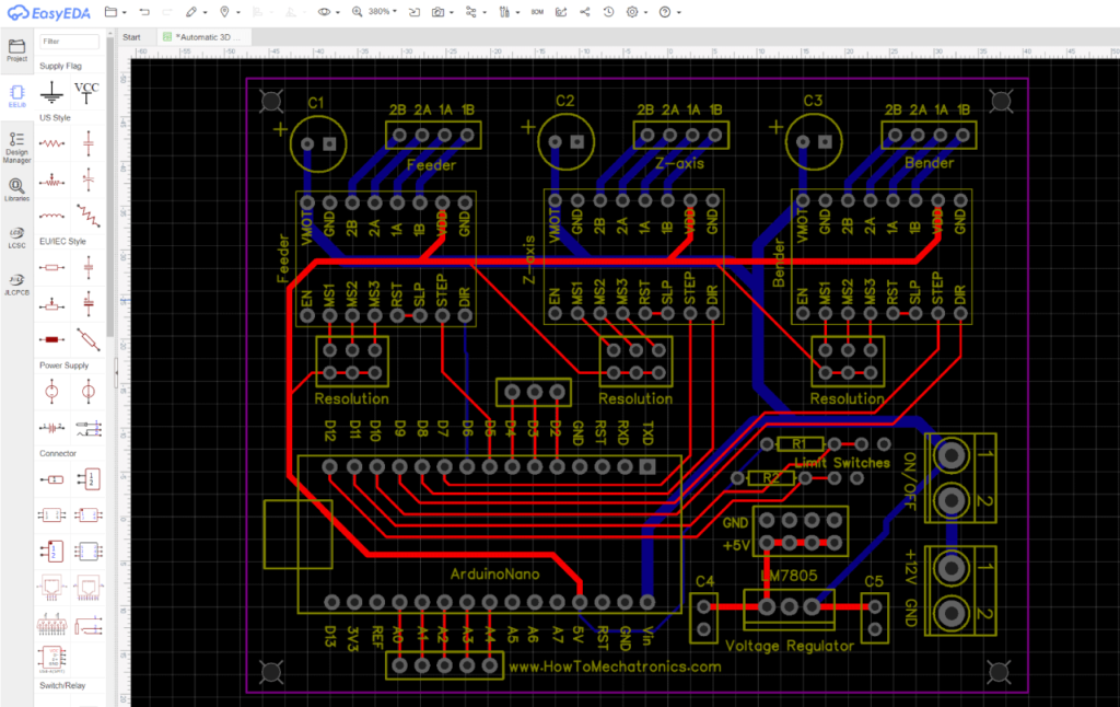
Here’s a link to the project files of this PCB design. So once finished with this design I generated the Gerber file needed for manufacturing the PCB.
Gerber file:
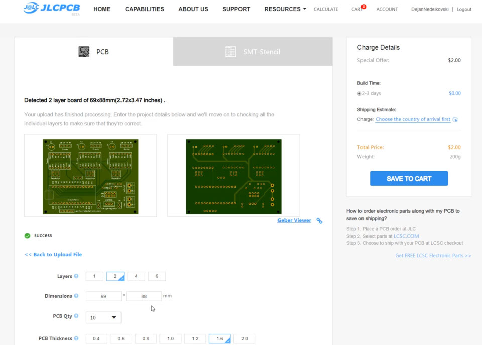
Then I ordered the PCB from JLCPCB, which is actually the sponsor of this project.

Here we can simply drag and drop the Gerber file and once uploaded, we can review our PCB in the Gerber viewer. If everything is all right then we can go on, select the properties that we want for our PCB, and then we can order our PCB at a reasonable price. Note that if it’s your first order from JLCPCB, you can get up to 10 PCBs for only $2.
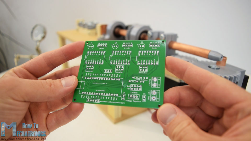
After several days the PCBs have arrived. The quality of the PCBs is great and everything is exactly the same as in the design.
So now we can move on and install the electronics components onto the PCB. I started by soldering pin headers to the PCB. This enables easier connecting and disconnecting of the components when needed. As for the smaller components, like the capacitors, the resistors, the voltage regulator and the terminal blocks I soldered them directly onto the PCB.
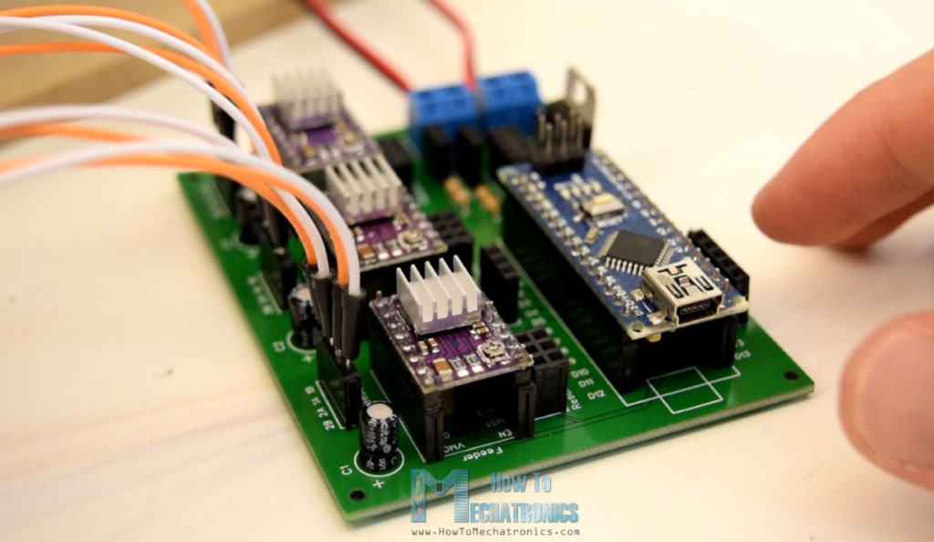
Once finished with this step, now we can insert the stepper drivers and the Arduino in place. Then we need connect the power plug and the power switch to the terminal blocks, connect the cables to the stepper motors on one side and connect them to the PCB on the other side. The servo is connected to digital pin number 2 and powered with the 5V coming from the LM7805 voltage regulator. Finally we can select stepper resolution by connecting the resolution pins below the drivers.
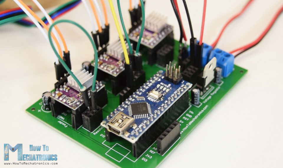
I decided to use 16th step resolution so we need to connect the right pins instead of the middle ones as seen on the photo above. So the electronic components are now ready and we can move on with programming the wire bending machine.
Arduino Code for 3D Wire Bending Machine Project
As the code is a bit longer, for better understanding, I will post the source code of the program in sections with description for each section. And at the end of this article I will post the complete source code.
For controlling the stepper motors I will use the AccelStepper library by Mike McCauley. So we need to include this library, as well as the servo library for controlling the servo motor. Then we need to define the pins to which the steppers are connected and some variables needed for the program below.
#include <AccelStepper.h>
#include <Servo.h>

#define limitSwitch 11

// Define the stepper motors and the pins the will use
AccelStepper feederStepper(1, 5, 6); // (Type:driver, STEP, DIR)
AccelStepper zAxisStepper(1, 7, 8);
AccelStepper benderStepper(1, 9, 10);

Servo servo01;
String dataIn = "";
String manualStatus = "";
int count = 0;
int dist;Code language: PHP (php)
In the setup section we set the initial position of the servo or the bending pin, and also set the initial position of the bender gear. This is done with the help of the limit switch. The stepper rotates toward the switch and once it’s pressed the motor starts counting the steps from zero and position itself to zero degrees, ready for bending.
void setup() {
  Serial.begin(9600);
  pinMode(limitSwitch, INPUT_PULLUP);
  servo01.attach(2);
  servo01.write(40); // Initial position, bending pin up
  // Stepper motors max speed
  feederStepper.setMaxSpeed(2000);
  zAxisStepper.setMaxSpeed(2000);
  benderStepper.setMaxSpeed(2000);
  // Homing
  while (digitalRead(limitSwitch) != 0) {
    benderStepper.setSpeed(1200);
    benderStepper.runSpeed();
    benderStepper.setCurrentPosition(0); // When limit switch pressed set position to 0 steps
  }
  delay(40);
  // Move 1400 steps from the limit switch to starting position
  while (benderStepper.currentPosition() != -1400) {
    benderStepper.setSpeed(-1200); // if negative rotates anti-clockwise
    benderStepper.run();
  }
  benderStepper.setCurrentPosition(0);
}Code language: JavaScript (javascript)
Now in the loop section, we wait for commands coming from the serial monitor. If we type manual, we will enter the manual bending mode or if we type for example star, the start() custom function will be executed and the machine will automatic make a star form for us.
void loop() {
  String mode = Serial.readString();
  if (mode.startsWith("manual")) {
    manual();
  }
  if (mode.startsWith("star")) {
    star();
  }
  if (mode.startsWith("cube")) {
    cube();
  }
  if (mode.startsWith("stand")) {
    stand();
  }
}Code language: JavaScript (javascript)
Let’s take a look at this custom function.
void star() {
  while (count != 5) {
    int feed = 38; //  mm
    int feedDistance = feed * 48; // 48- constats that map the mm value to number of steps the stepper show move
    while (feederStepper.currentPosition() != feedDistance) { // run until it reaches the distance value
      feederStepper.setSpeed(1200);
      feederStepper.run();
    }
    feederStepper.setCurrentPosition(0); // reset the current position to 0
    servo01.write(40); // Set the bender pin up
    delay(200);
    int angleConst = 18; // angle constant
    // Bend the wire 52 degrees
    while (benderStepper.currentPosition() != -52 * angleConst) {
      benderStepper.setSpeed(-700);
      benderStepper.run();
    }
    benderStepper.setCurrentPosition(0);
    delay(100);
    // Go back 52 degrees to initial position
    while (benderStepper.currentPosition() != 52 * angleConst) {
      benderStepper.setSpeed(1200);
      benderStepper.run();
    }
    benderStepper.setCurrentPosition(0);
    delay(100);
    // Feed the same distance again
    while (feederStepper.currentPosition() != feedDistance) {
      feederStepper.setSpeed(1200);
      feederStepper.run();
    }
    feederStepper.setCurrentPosition(0);
    delay(100);
    servo01.write(130); // Set the bender pin down
    delay(200);
    // Set bender to new initial position, for bending in the other direction
    while (benderStepper.currentPosition() != -42 * angleConst) {
      benderStepper.setSpeed(-1200);
      benderStepper.run();
    }
    benderStepper.setCurrentPosition(0);
    delay(200);
    servo01.write(40); // Bender pin up
    delay(200);
    while (benderStepper.currentPosition() != 105 * angleConst) {
      benderStepper.setSpeed(700);
      benderStepper.run();
    }
    benderStepper.setCurrentPosition(0);
    delay(50);
    while (benderStepper.currentPosition() != -63 * angleConst) {
      benderStepper.setSpeed(-1200);
      benderStepper.run();
    }
    delay(100);
    servo01.write(130);
    benderStepper.setCurrentPosition(0);
    count++;
  }
}Code language: JavaScript (javascript)
So here we enter a while loop which is executed 5 times, because obviously the star has 5 points. We start by setting the feed value, or that’s how much wire will be feed in millimeters. This value is then multiplied by 48 which translates feed value into appropriate steps for the stepper motor to move. Then using the run() function, we rotate the feeder motor with a speed set by the setSpeed() function. We stops when the above feedDistance value is reached, and right after that we set the current position value of the stepper zero.
int feed = 38; //  mm
    int feedDistance = feed * 48; // 48- constats that map the mm value to number of steps the stepper show move
    while (feederStepper.currentPosition() != feedDistance) { // run until it reaches the distance value
      feederStepper.setSpeed(1200);
      feederStepper.run();
    }
    feederStepper.setCurrentPosition(0); // reset the current position to 0Code language: JavaScript (javascript)
In the next step we bend the wire 52 degrees. This is done in similar way as explained above. Here we also have an angle constant which is multiplied with the desired angle. Once that value is reached by the motor, the motor stops, reset its current position to 0, and then runs the same number of steps in the opposite direction which actually returns the motor to its initial position.
// Bend the wire 52 degrees
    while (benderStepper.currentPosition() != -52 * angleConst) {
      benderStepper.setSpeed(-700);
      benderStepper.run();
    }
    benderStepper.setCurrentPosition(0);
    delay(100);
    // Go back 52 degrees to initial position
    while (benderStepper.currentPosition() != 52 * angleConst) {
      benderStepper.setSpeed(1200);
      benderStepper.run();
    }
    benderStepper.setCurrentPosition(0);
    delay(100);Code language: JavaScript (javascript)
Then again we feed the same length of wire and we set the pin down so that the bender can move to a new initial position which is used for bending in the other direction. The bender pin is then raised, and so we bend the wire 105 degrees in the opposite direction. The commands are repeated 5 times and that’s how we get the star form.
In similar way as explained above we make the cube shape or actually any other shape we can come up with. As for the manual mode, the working principle of the commands are the same, except that we have few more lines for reading the commands coming from the serial monitor. For example for feeding the wire, we need to type “f”, plus the distance in millimeters, for bending the wire, we need to type “b”, plus the angle in degrees, and for rotating the Z-axis, we need to type “z”, plus the angle in degrees.
if (dataIn.startsWith("f")) {
      dataInS = dataIn.substring(1, dataIn.length()); // reads the feed value
      dist = dataInS.toInt();
      Serial.print("Feed ");
      Serial.print(dist);
      Serial.println("mm wire.");
      dist = dist * 48;
      while (feederStepper.currentPosition() != dist) {
        feederStepper.setSpeed(1200);
        feederStepper.run();
      }
      feederStepper.setCurrentPosition(0);
      delay(100);
    }Code language: PHP (php)
So that’s how the program that I made works, but of course, there are many other ways this to be coded. Here’s the complete Arduino code for this 3D Wire Bending Machine:
/*
  Arduino 3D Wire Bending Machine
  by Dejan Nedelkovski
  www.HowToMechatronics.com
  Library - AccelStepper by Mike McCauley:
  http://www.airspayce.com/mikem/arduino/AccelStepper/index.html
*/

#include <AccelStepper.h>
#include <Servo.h>

#define limitSwitch 11

// Define the stepper motors and the pins the will use
AccelStepper feederStepper(1, 5, 6); // (Type:driver, STEP, DIR)
AccelStepper zAxisStepper(1, 7, 8);
AccelStepper benderStepper(1, 9, 10);

Servo servo01;
String dataIn = "";
String manualStatus = "";
int count = 0;
int dist;

void setup() {
  Serial.begin(9600);
  pinMode(limitSwitch, INPUT_PULLUP);
  servo01.attach(2);
  servo01.write(40); // Initial position, bending pin up
  // Stepper motors max speed
  feederStepper.setMaxSpeed(2000);
  zAxisStepper.setMaxSpeed(2000);
  benderStepper.setMaxSpeed(2000);
  // Homing
  while (digitalRead(limitSwitch) != 0) {
    benderStepper.setSpeed(1200);
    benderStepper.runSpeed();
    benderStepper.setCurrentPosition(0); // When limit switch pressed set position to 0 steps
  }
  delay(40);
  // Move 1400 steps from the limit switch to starting position
  while (benderStepper.currentPosition() != -1400) {
    benderStepper.setSpeed(-1200); // if negative rotates anti-clockwise
    benderStepper.run();
  }
  benderStepper.setCurrentPosition(0);
}

void loop() {
  String mode = Serial.readString();
  if (mode.startsWith("manual")) {
    manual();
  }
  if (mode.startsWith("star")) {
    star();
  }
  if (mode.startsWith("cube")) {
    cube();
  }
  if (mode.startsWith("stand")) {
    stand();
  }
}
void star() {
  while (count != 5) {
    int feed = 38; //  mm
    int feedDistance = feed * 48; // 48- constats that map the mm value to number of steps the stepper show move
    while (feederStepper.currentPosition() != feedDistance) { // run until it reaches the distance value
      feederStepper.setSpeed(1200);
      feederStepper.run();
    }
    feederStepper.setCurrentPosition(0); // reset the current position to 0
    servo01.write(40); // Set the bender pin up
    delay(200);
    int angleConst = 18; // angle constant
    // Bend the wire 52 degrees
    while (benderStepper.currentPosition() != -52 * angleConst) {
      benderStepper.setSpeed(-700);
      benderStepper.run();
    }
    benderStepper.setCurrentPosition(0);
    delay(100);
    // Go back 52 degrees to initial position
    while (benderStepper.currentPosition() != 52 * angleConst) {
      benderStepper.setSpeed(1200);
      benderStepper.run();
    }
    benderStepper.setCurrentPosition(0);
    delay(100);
    // Feed the same distance again
    while (feederStepper.currentPosition() != feedDistance) {
      feederStepper.setSpeed(1200);
      feederStepper.run();
    }
    feederStepper.setCurrentPosition(0);
    delay(100);
    servo01.write(130); // Set the bender pin down
    delay(200);
    // Set bender to new initial position, for bending in the other direction
    while (benderStepper.currentPosition() != -42 * angleConst) {
      benderStepper.setSpeed(-1200);
      benderStepper.run();
    }
    benderStepper.setCurrentPosition(0);
    delay(200);
    servo01.write(40); // Bender pin up
    delay(200);
    while (benderStepper.currentPosition() != 105 * angleConst) {
      benderStepper.setSpeed(700);
      benderStepper.run();
    }
    benderStepper.setCurrentPosition(0);
    delay(50);
    while (benderStepper.currentPosition() != -63 * angleConst) {
      benderStepper.setSpeed(-1200);
      benderStepper.run();
    }
    delay(100);
    servo01.write(130);
    benderStepper.setCurrentPosition(0);
    count++;
  }
}

void cube() {
  int feed = 40; //  mm
  int feedDistance = feed * 48;
  int angleConst = 16;
  // Step 1
  while (count != 3) {
    while (feederStepper.currentPosition() != feedDistance) {
      feederStepper.setSpeed(1200);
      feederStepper.run();
    }
    feederStepper.setCurrentPosition(0);
    delay(100);
    while (benderStepper.currentPosition() != -90 * angleConst) {
      benderStepper.setSpeed(-700);
      benderStepper.run();
    }
    benderStepper.setCurrentPosition(0);
    delay(100);
    while (benderStepper.currentPosition() != 90 * angleConst) {
      benderStepper.setSpeed(1200);
      benderStepper.run();
    }
    benderStepper.setCurrentPosition(0);
    delay(100);
    count++;
  }
  count = 0;
  // Step 2
  while (zAxisStepper.currentPosition() != 88 * angleConst) {
    zAxisStepper.setSpeed(500);
    zAxisStepper.run();
  }
  zAxisStepper.setCurrentPosition(0);
  delay(100);
  //Step 3
  while (count != 2) {
    while (feederStepper.currentPosition() != feedDistance) {
      feederStepper.setSpeed(1200);
      feederStepper.run();
    }
    feederStepper.setCurrentPosition(0);
    delay(100);
    while (benderStepper.currentPosition() != -90 * angleConst) {
      benderStepper.setSpeed(-700);
      benderStepper.run();
    }
    benderStepper.setCurrentPosition(0);
    delay(100);
    while (benderStepper.currentPosition() != 90 * angleConst) {
      benderStepper.setSpeed(1200);
      benderStepper.run();
    }
    benderStepper.setCurrentPosition(0);
    delay(100);
    count++;
  }
  count = 0;
  // Step 4
  while (zAxisStepper.currentPosition() != 85 * angleConst) {
    zAxisStepper.setSpeed(500);
    zAxisStepper.run();
  }
  zAxisStepper.setCurrentPosition(0);
  delay(100);
  // Step 5
  servo01.write(130);
  delay(200);
  while (benderStepper.currentPosition() != -42 * angleConst) {
    benderStepper.setSpeed(-1200);
    benderStepper.run();
  }
  benderStepper.setCurrentPosition(0);
  while (count != 3) {
    delay(100);
    servo01.write(40);
    delay(200);
    // Step 6
    while (feederStepper.currentPosition() != feedDistance) {
      feederStepper.setSpeed(1200);
      feederStepper.run();
    }
    feederStepper.setCurrentPosition(0);
    delay(100);
    while (benderStepper.currentPosition() != 90 * angleConst) {
      benderStepper.setSpeed(700);
      benderStepper.run();
    }
    benderStepper.setCurrentPosition(0);
    delay(100);
    while (benderStepper.currentPosition() != -90 * angleConst) {
      benderStepper.setSpeed(-1200);
      benderStepper.run();
    }
    benderStepper.setCurrentPosition(0);
    delay(100);
    count++;
  }
  count = 0;
}

void stand() {
  int feed = 20; // mm
  int feedDistance = feed * 48;
  int angleConst = 16;
  // Step 1
  while (feederStepper.currentPosition() != feedDistance) {
    feederStepper.setSpeed(1200);
    feederStepper.run();
  }
  feederStepper.setCurrentPosition(0);
  delay(100);
  while (benderStepper.currentPosition() != -90 * angleConst) {
    benderStepper.setSpeed(-700);
    benderStepper.run();
  }
  benderStepper.setCurrentPosition(0);
  delay(100);
  while (benderStepper.currentPosition() != 90 * angleConst) {
    benderStepper.setSpeed(1200);
    benderStepper.run();
  }
  benderStepper.setCurrentPosition(0);
  delay(100);

  // Step 2
  while (feederStepper.currentPosition() != feedDistance) {
    feederStepper.setSpeed(1200);
    feederStepper.run();
  }
  feederStepper.setCurrentPosition(0);
  delay(100);
  while (benderStepper.currentPosition() != -70 * angleConst) {
    benderStepper.setSpeed(-700);
    benderStepper.run();
  }
  benderStepper.setCurrentPosition(0);
  delay(100);
  while (benderStepper.currentPosition() != 70 * angleConst) {
    benderStepper.setSpeed(1200);
    benderStepper.run();
  }
  benderStepper.setCurrentPosition(0);
  delay(100);

  // Step 3
  feed = 80; // mm
  feedDistance = feed * 48;
  while (feederStepper.currentPosition() != feedDistance) {
    feederStepper.setSpeed(1200);
    feederStepper.run();
  }
  feederStepper.setCurrentPosition(0);
  delay(100);
  // Step 4
  servo01.write(130);
  delay(200);
  while (benderStepper.currentPosition() != -42 * angleConst) {
    benderStepper.setSpeed(-1200);
    benderStepper.run();
  }
  benderStepper.setCurrentPosition(0);
  delay(100);
  servo01.write(40);
  delay(200);
  while (benderStepper.currentPosition() != 108 * angleConst) {
    benderStepper.setSpeed(700);
    benderStepper.run();
  }
  benderStepper.setCurrentPosition(0);
  delay(100);
  while (benderStepper.currentPosition() != -66 * angleConst) {
    benderStepper.setSpeed(-1200);
    benderStepper.run();
  }
  benderStepper.setCurrentPosition(0);

  //Step 5
  servo01.write(130);
  delay(200);
  // Step 6
  feed = 80; // mm
  feedDistance = feed * 48;
  while (feederStepper.currentPosition() != feedDistance) {
    feederStepper.setSpeed(1200);
    feederStepper.run();
  }
  feederStepper.setCurrentPosition(0);
  servo01.write(40);
  delay(200);
  // Step 7
  while (zAxisStepper.currentPosition() != -90 * angleConst) {
    zAxisStepper.setSpeed(-500);
    zAxisStepper.run();
  }
  zAxisStepper.setCurrentPosition(0);
  delay(100);

  // Step 8
  while (benderStepper.currentPosition() != -90 * angleConst) {
    benderStepper.setSpeed(-700);
    benderStepper.run();
  }
  benderStepper.setCurrentPosition(0);
  delay(100);
  while (benderStepper.currentPosition() != 90 * angleConst) {
    benderStepper.setSpeed(1200);
    benderStepper.run();
  }
  benderStepper.setCurrentPosition(0);
  delay(100);
  // Step 6
  feed = 45; // mm
  feedDistance = feed * 48;
  while (feederStepper.currentPosition() != feedDistance) {
    feederStepper.setSpeed(1200);
    feederStepper.run();
  }
  feederStepper.setCurrentPosition(0);
  // Step 10
  while (benderStepper.currentPosition() != -90 * angleConst) {
    benderStepper.setSpeed(-700);
    benderStepper.run();
  }
  benderStepper.setCurrentPosition(0);
  delay(100);
  while (benderStepper.currentPosition() != 48 * angleConst) {
    benderStepper.setSpeed(1200);
    benderStepper.run();
  }
  benderStepper.setCurrentPosition(0);
  delay(100);

  // Step 11
  while (zAxisStepper.currentPosition() != 90 * angleConst) {
    zAxisStepper.setSpeed(500);
    zAxisStepper.run();
  }
  zAxisStepper.setCurrentPosition(0);
  delay(100);
  feed = 80; // mm
  feedDistance = feed * 48;
  while (feederStepper.currentPosition() != feedDistance) {
    feederStepper.setSpeed(1200);
    feederStepper.run();
  }
  feederStepper.setCurrentPosition(0);

  // Step 12
  while (benderStepper.currentPosition() != 110 * angleConst) {
    benderStepper.setSpeed(700);
    benderStepper.run();
  }
  benderStepper.setCurrentPosition(0);
  delay(100);
  while (benderStepper.currentPosition() != -68 * angleConst) {
    benderStepper.setSpeed(-1200);
    benderStepper.run();
  }
  benderStepper.setCurrentPosition(0);
  //Step 13
  servo01.write(130);
  delay(200);
  feed = 80; // mm
  feedDistance = feed * 48;
  while (feederStepper.currentPosition() != feedDistance) {
    feederStepper.setSpeed(1200);
    feederStepper.run();
  }
  feederStepper.setCurrentPosition(0);
  servo01.write(40);
  delay(200);

  // Step 14
  while (benderStepper.currentPosition() != -70 * angleConst) {
    benderStepper.setSpeed(-700);
    benderStepper.run();
  }
  benderStepper.setCurrentPosition(0);
  delay(100);
  while (benderStepper.currentPosition() != 70 * angleConst) {
    benderStepper.setSpeed(1200);
    benderStepper.run();
  }
  benderStepper.setCurrentPosition(0);
  delay(100);

  //Step 15
  feed = 25; // mm
  feedDistance = feed * 48;
  while (feederStepper.currentPosition() != feedDistance) {
    feederStepper.setSpeed(1200);
    feederStepper.run();
  }
  feederStepper.setCurrentPosition(0);
  delay(100);
  // Step 16
  while (benderStepper.currentPosition() != -90 * angleConst) {
    benderStepper.setSpeed(-700);
    benderStepper.run();
  }
  benderStepper.setCurrentPosition(0);
  delay(100);
  while (benderStepper.currentPosition() != 90 * angleConst) {
    benderStepper.setSpeed(1200);
    benderStepper.run();
  }
  benderStepper.setCurrentPosition(0);
  delay(100);

  // Step 17
  while (feederStepper.currentPosition() != feedDistance) {
    feederStepper.setSpeed(1200);
    feederStepper.run();
  }
  feederStepper.setCurrentPosition(0);
}

void manual() {
  int sign;
  String dataInS;
  int angle;
  int angleConst;
  Serial.println("  // MANUAL MODE //");
  while (!dataIn.startsWith("end")) {
    servo01.write(130);
    delay(200);
    dataIn = Serial.readString();
    if (dataIn.startsWith("f")) {
      dataInS = dataIn.substring(1, dataIn.length()); // reads the feed value
      dist = dataInS.toInt();
      Serial.print("Feed ");
      Serial.print(dist);
      Serial.println("mm wire.");
      dist = dist * 48;
      while (feederStepper.currentPosition() != dist) {
        feederStepper.setSpeed(1200);
        feederStepper.run();
      }
      feederStepper.setCurrentPosition(0);
      delay(100);
    }
    if (dataIn.startsWith("b")) {
      if (dataIn.charAt(1) == '-') {
        dataInS = dataIn.substring(2, dataIn.length()); ///reads the angle value
        angle = dataInS.toInt();
        Serial.print("Bend -");
        Serial.print(angle);
        Serial.println(" degrees.");
        angleConst = 16;
        // Set "negative" bending initial position
        while (benderStepper.currentPosition() != -43 * angleConst) {
          benderStepper.setSpeed(-1200);
          benderStepper.run();
        }
        benderStepper.setCurrentPosition(0);
        delay(100);
        servo01.write(40);
        delay(200);
        // Bend the wire
        while (benderStepper.currentPosition() != angle * angleConst) {
          benderStepper.setSpeed(700);
          benderStepper.run();
        }
        benderStepper.setCurrentPosition(0);
        delay(100);
        while (benderStepper.currentPosition() != (-1) * angle * angleConst) {
          benderStepper.setSpeed(-1200);
          benderStepper.run();
        }
        benderStepper.setCurrentPosition(0);
        delay(100);
        servo01.write(130);
        delay(200);
        // Get back to original "positive" bending initial poistion
        while (benderStepper.currentPosition() != 43 * angleConst) {
          benderStepper.setSpeed(1200);
          benderStepper.run();
        }
        benderStepper.setCurrentPosition(0);
        delay(100);
      }
      else {
        dataInS = dataIn.substring(1, dataIn.length());
        angle = dataInS.toInt();
        Serial.print("Bend ");
        Serial.print(angle);
        Serial.println(" degrees.");
        angleConst = 16;
        servo01.write(40);
        delay(200);
        while (benderStepper.currentPosition() != (-1) *angle * angleConst) {
          benderStepper.setSpeed(-700);
          benderStepper.run();
        }
        benderStepper.setCurrentPosition(0);
        delay(100);
        while (benderStepper.currentPosition() != angle * angleConst) {
          benderStepper.setSpeed(1200);
          benderStepper.run();
        }
        benderStepper.setCurrentPosition(0);
        delay(100);
      }
      dataInS = dataIn.substring(2, dataIn.length());
      angle = dataInS.toInt();
      angleConst = 16;
      while (benderStepper.currentPosition() != sign * angle * angleConst) {
        benderStepper.setSpeed(-700);
        benderStepper.run();
      }
      benderStepper.setCurrentPosition(0);
      delay(100);
      while (benderStepper.currentPosition() != sign * angle * angleConst) {
        benderStepper.setSpeed(1200);
        benderStepper.run();
      }
      benderStepper.setCurrentPosition(0);
      delay(100);
    }
    // Z-Axis Control
    if (dataIn.startsWith("z")) {
      if (dataIn.charAt(1) == '-') {
        dataInS = dataIn.substring(2, dataIn.length());
        angle = dataInS.toInt();
        Serial.print("Move Z-Axis -");
        Serial.print(angle);
        Serial.println(" degrees.");
        angleConst = 16;
        while (zAxisStepper.currentPosition() != angle * angleConst) {
          zAxisStepper.setSpeed(500);
          zAxisStepper.run();
        }
        zAxisStepper.setCurrentPosition(0);
        delay(100);
      }
      else {
        dataInS = dataIn.substring(1, dataIn.length());
        angle = dataInS.toInt();
        Serial.print("Move Z-Axis ");
        Serial.print(angle);
        Serial.println(" degrees.");
        angleConst = 16;
        while (zAxisStepper.currentPosition() != (-1) *angle * angleConst) {
          zAxisStepper.setSpeed(-500);
          zAxisStepper.run();
        }
        zAxisStepper.setCurrentPosition(0);
        delay(100);
      }
    }
    manualStatus = dataIn;
  }
}
Code language: PHP (php)
At the end I would like to point out that the wire straightening system of the wire bending machine is actually not working like it should work, because if I tighten it more, the feeder loses grip and the wire doesn’t move.
For solving this issue you could try to use different, stronger material than the copper tube or make a different feeder system.
So that’s it. I hope you enjoyed this video and learned something new. Feel free to ask any question in the comments section below and check my Arduino Projects Collection.
Hello, thanks for your project, i’m trying to do it for a school work. With the weight of the NEMA23, the ZAxis motor can’t turn well, when i remove the parts at the end of the coil shaft (NEMA 23, servomotor etc…) the motor can turn well.
Do you know what is the problem ? Is taht because i am using a 12V 2A power supply ? thanks
Hi, try increase the current limit of the stepper motor, it will increase the power of the motor. Though be careful the driver might overheat.
Would it be possible to change the solidworks files over to sketchup files. Or could you send me dxf files for the frame and housing to cut out on my cnc.
Thanks
Hi Great project, I am starting to get the parts together now, as I live in the UK will I need to take in to account the single faze voltage here is 230V when ordering the electrical parts.
I was wondering about how to choose the motors for the project in terms of torque, number of turns, steps, etc. …. And I was wondering about what I relied on to construct the gears used and the diameter of the copper tubes
I wait eagerly for the reply and thanks for sharing the project
Hey, well to be honest the choice here for the motors, the gears and so on, was almost like arbitrary. Still, this is just a simple project showing the idea of making such a machine, while not going into details in designing or even coding it the proper way.
wow it is great project. can we use other arduino boards like arduino UNO for this project?
Yes, sure, you can use any Arduino board for the project.
Hi Dejan, i just have a cuestion, why in the PCB appear two limit switch?? one is for the limit of the Bender,and the other????
Hey, I used only 1 limit switch for this project. I added one more limit switch to the PCB just in case I need it for something in future, but I actually didn’t use it.
Hello Dejan,
It is a great project, I build it with some modifications.
i replace your feeder by 3d printer filament feeder and it is great.
but i still suffer from wire rotating about Z-axis.
I am printing another straightener (vertical) to add it after the one you put it, I saw this application before i hope it goes right.
Did you get the solution till now?
Hey, thanks! It sounds like you have made quite an upgrade. Maybe the vertical straightener will solve the problem. I haven’t tried to find a solution for that problem, but I a good straightening system would solve that problem definitely.
And capacitor specification for Lm7805 voltage regulator,
Thank you
Hi, I’m part way through producing one of these & we’re about to use it as a project with a local college. Unfortunately, the download links no longer seem to work – it used to open up a login window, but now just greys the page and has a spinning logo. Is it possible you could email me the part files?
Hey, try to use different web browser.
Hello Dejan,
Do I have to make any changes if I use Arduino UNO instead of NANO,
If yes then what changes I have to make?
Hey, sure, you can use an Arduino Uno instead of Nano. You don’t need to change anything particular, you just need to make sure that you connect everything properly and define the pins to the Arduino appropriately.
Give Capacitor specification
And
Can I use 12v 5a power supply in this circuit
Yes, you can use 12V 5A power supply. As for the capacitors for the stepper motors you should use something around 100uF with voltage rating of 50V or above.
Pretty interesting…
What size of wire (diameter) (& steel/aluminium?) can be bent using this?
I used 2mm steel wire. Anything thinker than this would need different design or more powerful motor for bending.
hello Dejan,
Were are a group of architecture students learning how to make and program the wire bender. Some of the problems we are running into are the stepper motors not turning, they are receiving the code, but they are stuck. We don’t know if it is a wiring problem, or if it is a coding problem. We were hoping to get some more info on how the wiring is completed.
I hope to hear from you soon.
Hey, it’s probably wiring problem. Try to make a simpler example using just a single stepper in order to make sure it works properly. Try the examples from my separate dedicated tutorial on using steppers with Arduino.
Hello,
We followed your other tutorial, and it really helped with the two NEMA 17 stepper motors, but we are having difficulty figuring how the limit switch connects to the board. We were just wondering if you could perhaps explain how it plugs in to the board.
Thanks
Well you should follow the circuit diagram for connecting the limit switch. One pin goes to ground and the other pin goes to a digital pin of the Arduino, while the same pin also goes through a resistor to 5V. When the limit switch will be pressed the input to this digital pin will drop LOW, otherwise it’s constantly HIGH, or maybe vice versa if you connect the other two pins of the limit switch, in case you have 3 pins limit switch as shown in the diagram.
Hi Dejan,
Thank you for the feedback in the previous post. You effectively communicated the concept of the ‘angleconst’. With that said, I have an additional question.
In a previous comment you said that the code responsible for making shapes/models like stars and cube were “manually coded in the Arduino IDE”. Do you mean to say that 1) you manually coded them in through trial and error or you 2) you found a library with code online? I am asking because I am interested in making additional shapes.
I look forward to your response.
Hi Dejan, thank your for creating a how-to guide for this 3d bending machiens .
My engineering senior design team and I are in the process of recreating (w/ some mods) the machine.
I have some questions regarding your code. What does angleConst mean? I notice that the int value you assign to the variable changes throughout the different ‘shape’ functions. For example, for the ‘star’ function your angleconst = 18, and for ‘cube’ and ‘stand’ it is 16. Why those values?
Thank you. I look forward to your response.
Hey, well those constants are manually set to fit the shapes I was making. I already mention the code is not really good, it can be improved quite a bit. The idea for those constants is that the stepper motor has 200 steps, working a 16th step resolution that’s total of 3200 steps. So to move 90 degrees we need 50 steps, t.e 800 microsteps. 800steps / 90deg = 8.88 or in case of 32th step resolution that’s around 1600steps/90deg = 17.77. So I might have been using 32th step resolution so that’s why these numbers are around 16-18.
Can you tell which version of Solidworks you are using?
It’s the version 2017.
Such an awesome project! I’ve been addicted in it for a while now.. I’ll be trying to do my own based on this on the next few days. Would you mind posting more info about the electrical part? I mean, I’m willing to power my system (which uses 3 NEMA17 of 3.5kgf/cm 1.2A) with a DC 12V 3A P4 Jack power supply, but I’m wondering how did you power supplied your system or even how would you plug this P4 jack on the PCB. Thank you and congrats!
Thanks! Although I have stated so, 3A power supply might not be enough. Each stepper can pull 1A or even 1.5A. I mean, sure you can limit the current with the drivers, for example to 0.5A each or something, but then you might not have enough torque. You can use P4 jack, simply solder it to the PCB using two wires.
Very nice prototype. The bearing drag issue can be corrected by using components from a wire feed component from a MIG welding machine, I used one from Aliexpress. They can provide knurled wheels of different wire sizes, I got 0.045″ and 1/8″ wire sizes. The one I built based on other youtube videos without as much detail as you have, and CNC pipe benders I have seen. I had some various weakness, as well. I had two main issues with mine, the head was way too weak. The other was programming, you made it much further than I did. I would like to use your approach to see if I can take it further, may not get anywhere but worth looking into. Again, very impressive work.
Thank you! Well I guess it would be easier for your to make improvements to your and this design as you already have experience with this. I’ve noticed people who tried making thing prototype faced some difficulties, and it’s true, it’s not that easy to get it working, you need to be prepared for troubleshooting. After all, it’s just a prototype or more like an educational project for learning new skills. Thanks again for the input!
This has got to be one of the most impressive and well documented projects I have ever seen. Wow. It is especially helpful that you released all the file to build it. I understand that there is more development work needed but just the same, really great. Thank you for sharing.
Thank you!
Hello Dejan,
That coding uses for specific models (like star,cube) as I understand.
I would like to do complex models (like spline,spring ec.. )
Is possible that to do my draft which is created in Solidworks with arduino codes ?
For example, CURA is program which is using by 3d printer. I give STL model in CURA program, it prepares appropriate codes for 3d printer.
Is there such a program for wire bending ?
Hey, the specific models are manually coded in the Arduino IDE. The program that I’ve made can only do such a shapes, manually coded. So no, you cannot make something in Solidworks or any other software so the machine would make it automatically that shape. Of course that’s possible, but it needs some serious coding to make that possible.
I’m about to finish the project. I have a problem with the wire feeder. if it travels the distance that I write to it but when it is bending the cable it turns unexpectedly on the z axis. I do not know if you or someone else has a clear idea that is functional so that the machine works correctly. because I have to be aware of the cable and that what is bending does not deviate at the same time
Hey, well that’s kind of a problem I was experiencing too. You need to somehow make the wire stays straight or don’t rotate around the z axis. Again it has to do with the gripper mechanism, it has to be made better to work properly and don’t allow the wire to rotate. It’s a bit tricky as the wire is tin in the first place and can easily deform.
AWESOME!!!!
I did a little tweak to your design…made the wires a little bigger for better power and signal…still such a COOL project!
Hi Dejan.
I’ve built this machine according to your specs, and it’s useless…
Or I’ve made some serious errors during construction…
It won’t bend a 0,5mm brass wire without stalling at the tip at some point.
The Z-axis won’t turn above 5 degrees and there’s nothing keeping the wire from turning (z-axis) on it’s own…
I knew the feeder action was questionable from the start so I’m not blaming you for that… 😉
Any immediate thoughts on what might be the problem?
Peter
PS. I have only used the components specified in your BOM…
Hi Peter,
Actually I had the same problems. The machine is far from perfect.
Try to increase the stepper drivers current limit. You can do that using the small screw on the driver. In that way the steppers will draw more current and will have enough power to bend the wire and turn the Z-axis.
It’s true, the Z-axis motor is on it’s limit of turning the shaft, even at higher driver current limit but it still works, as seen on my video. As for the bender try the same thing, and also try to increase the distance from the nozzle to the bending pin, or shorten the nozzle or the shaft.
It’s also true that the wire tends to turns along with the Z-axis, which eventually disturbs the form you are making.
Sorry for not pointing all of these things in the video. But you know, these kind of videos and tutorials should not be taken for granted. You will always need to modify something.
Hello, Dejan.
I am a mechanical education student and have also chosen this project for this semester. Can you convert the Solidworks files into dwg or dxf?
Thanks in advance
Greeting
Hey, you can use the .STEP file and open it using Autodesk Fusion 360.
How did you know what the feed rate was? I was wondering how you calculated the force needed to send the wire through the entire assembly.
Well the feed rate depends on the circumference of the feeder. If it’s 22mm in diamter, such as in my case, the circumference is 69.115mm, so full rotation of the feeder will feed 69.11mm wire. However, you should simply test it out and measure what you get with your feeder.
hey,Dejan .
I am student on mechanical enng, and I have choosen this project for thiz semester , could you send me the solidworks link ,?
If that wont be anything for you//
hope to hear soon from you.
Hey, the 3D models files are already provided in the article above, you can freely download them.
In your photos, you have a plastic mount with gear attached, described as ” This gear will be paired with bigger 30 teeth gear which is a custom designed gear with integrated plate for mounting a MG996R servo” – I can’t find this object in the STL files anywhere, is it missing?
That’s the file “bender gear modified”.
Hi Dejan
This wonderful project should be mandatory for all engineering students.
Covers: Mechanics, electronics, CAD, pcb design, embedded programming, hand tools and 3d printing.
Would love to see a video/article by you on 3d printing.
Thanks
Thank you! Yeah, I will definitely keep creating content like this, I enjoy making it and I love when people find it useful and like it. 🙂
Your work is really well done! It allows for student for example to mix different aspects of their teaching. Thanks a lot for that! If there was a suggestion: a complete list of material can be interesting to av oid missing a component.
Hi Dejan,
This is a great project! I Love it.
Very well explained (not too detailed just right).
Thanks for sharing this.
Cant wait for other stuff from you!
Michel
Thanks!
Hi Dejan,
this is a great project! Thanks for sharing this.
Is it possible that you add a complete list of all materials used to make it easier to recreate this project?
It would be great if you could provide the corresponding links to Amazon / Banggood too (if possible).
In addition:
The Servo Motor SDLPRT is missing in the rar-file.
Keep on with the good work 🙂
Thank you! Well the list of the main components can be found in the article above, in the section where the circuit diagram is. I guess you have seen them and as for the others they are regular common components, like the capacitors and the LM7805 voltage regulator. I actually added the micro limit switch in the list.
And thanks for the comment for the missing part, I added it both in the STEP and Solidworks file. I’ve just updated the article. 🙂
Hi,
Great project.
What size ball bearings did you use to make the rollers?
Thanks.
Abok
The ball bearings for the rollers are 608Z, 22mm OD, 8mm ID, 7mm W.
Hey Dejan,
I love the project! As far as your wire feeder losing grip, could you perhaps put a small radius wide rubber band on the copper to increase grip?
Thank you! I thought of it but I’m afraid a rubber would very quickly tear out.
Hi Dejan, great project! did you print the pieces in PLA? how % infill did you used? Regards,
Hey, thanks! Yes, I printed the parts in PLA, I think with 35 % infill. 🙂
Hi Dejan,
what a great project. i can not wait to start building it. i noticed is your links to part the Arduino link show that Arduino MEGA but the PCB is made for the Arduino NANO. did you make a change to design?
Best Regards
David
Hey, thanks! Sorry I’ve put wrong links. Now the part list is updated, the Arduino Nano is what you need for sure.
where is the gerber file? i have all the printed parts, and am cutting the wood now. i have no experience with designing a pcb, and no idea where to find the gerber file i am supposed to upload to the pcb maker.
thanks
Hey, I updated the article and included the Gerber file in the PCB design section above. You can order the PCB just as explained in the video or in the text.