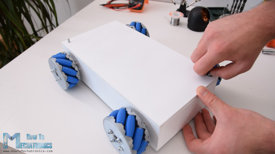
In this tutorial we will learn how to build an Arduino Mecanum Wheels Robot which is capable of moving in any direction. This unique mobility of the robot is achieved by using special type of wheels, called Mecanum Wheels.
You can watch the following video or read the written tutorial below.
Overview
I actually designed and 3D printed these wheels because they can be a bit expensive to buy. They work quite well and I must say that driving this robot platform is so fun. We can wirelessly control the robot using the NRF24L01 radio transceiver modules, or in my case, I’m using my DIY RC Transmitter which I made in one of my previous videos.
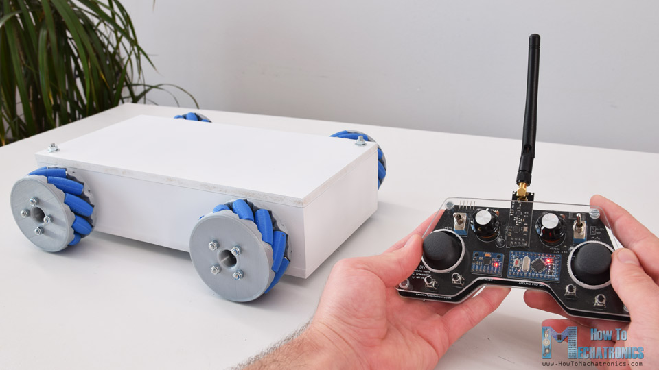
I also made it possible to be controlled using a smartphone via Bluetooth communication. I made a custom Android application through which we can control the Mecanum wheels robot to move in any direction. Also, using the slider in the app we can control the speed of movement.
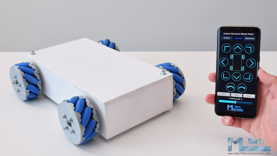
The brain of this robot platform is an Arduino Mega board which controls each wheel individually. Each wheel is attached on a NEMA 17 stepper motor, and knowing the fact that stepper motors can be precisely controlled, I added one more cool feature in the app through which we can program the robot to move automatically. Using the Save button we can save each position or step and then the robot can automatically run and repeat these steps. With the same button we can pause the automatic operation as well as reset or delete all steps so we can store new ones.
Mecanum Wheels Robot 3D Model
To begin with, I designed this Mecanum Wheels robot using a 3D modeling software. The base platform of this robot is a simple box which I will make out of 8mm tick MDF boards.
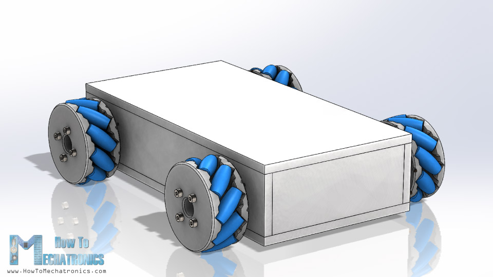
The four stepper motors are attached to this platform and the Mecanum wheels are attached to the motor’s shafts.
You can get this 3D model, as well as the STL files for 3D Printing from Cults3D.
How Mecanum Wheels Work
A Mecanum wheel is a wheel with rollers attached to its circumference. These rollers are positioned diagonally or at 45-degree angle to the axis of rotation of the wheel. This makes the wheel exert force in diagonal direction when moving forward of backward.
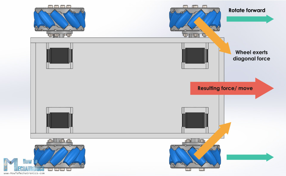
So, by rotating the wheels in certain pattern, we utilize these diagonal forces and thus the robot can move in any direction.
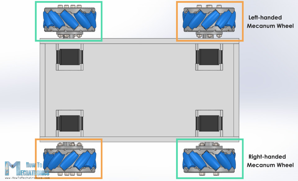
We should also note here that we need two types of Mecanum wheels, often referred to as, left-handed and right-handed Mecanum wheels. The difference between them is the orientation of the rollers and they must be installed in the robot in specific locations. The rotation axis of each wheel’s top roller should point to the center of the robot.
Here’s a quick demonstration of how to robot moves depending on the wheels rotation direction.
If all four wheels move forward, the resulting move of the robot will be forward, and vice versa if all wheels move backward the robot will move backward. For moving to the right, the right wheels need rotate inside the robot, while the left wheels need rotate outside the robot. The resulting force due to the diagonally positioned rollers will make the robot move to the right. The same but opposite happens when moving to the left. With these wheels we can also achieve movement in diagonal direction by rotating only two wheels.
Making the Mecanum Wheels Robot
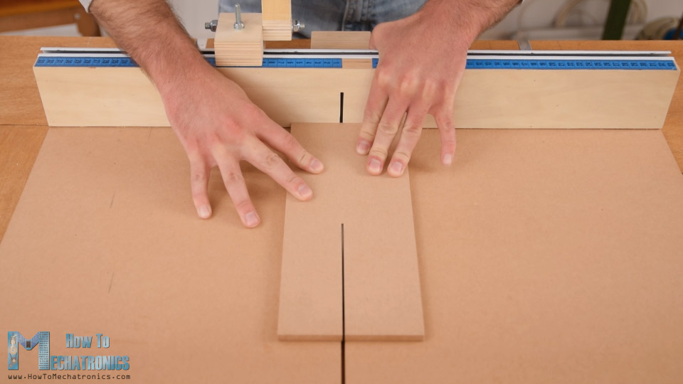
Nevertheless, now let me show you how I built this robot platform. As I mentioned, for making the base of the platform I’m using 8mm tick MDF boards. Using a table saw, first I cut all of the pieces according to the 3D model dimensions.
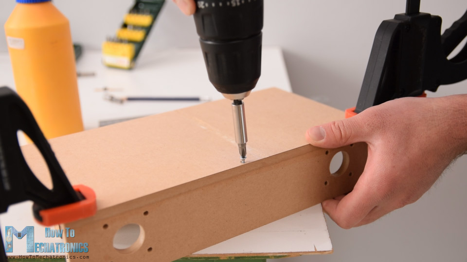
Next, using a 3mm drill and a 25mm Forstner bit I made the openings on the side panels for attaching the stepper motors. Once I got the pieces ready, I continued with assembling them. I used a wood glue and some screws for securing them. The most important thing here is to have the openings for the motors precisely made so that all of the wheels have even contact with the surface later on.
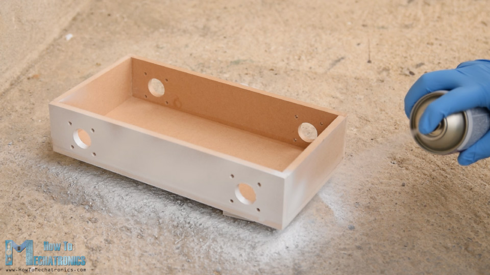
Of course, you could also 3D print this base platform, instead of making it with MDF, so I will include a 3D file of it on the website article. Finally, I spray painted the base and it’s cover with white color.
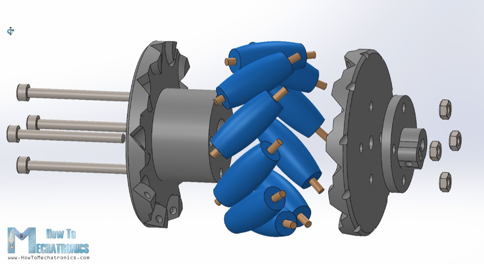
Next are the Mecanum wheels. As I said earlier, these wheels can be a bit expensive to buy, so that’s why I decided to design and 3D print my own ones. The wheels are made out of two parts, outer and inner side which are secured together with some M4 bolts and nuts. They have 10 rollers each, and a shaft coupler specifically designed to fit a NEMA 17 stepper motor.
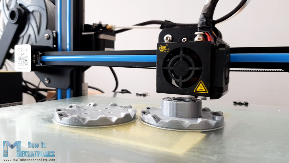
I 3D printed all of the parts for the Mecanum wheels using my Creality CR-10 3D printer.
Here’s a link to this 3D printer in case you want to check it out.
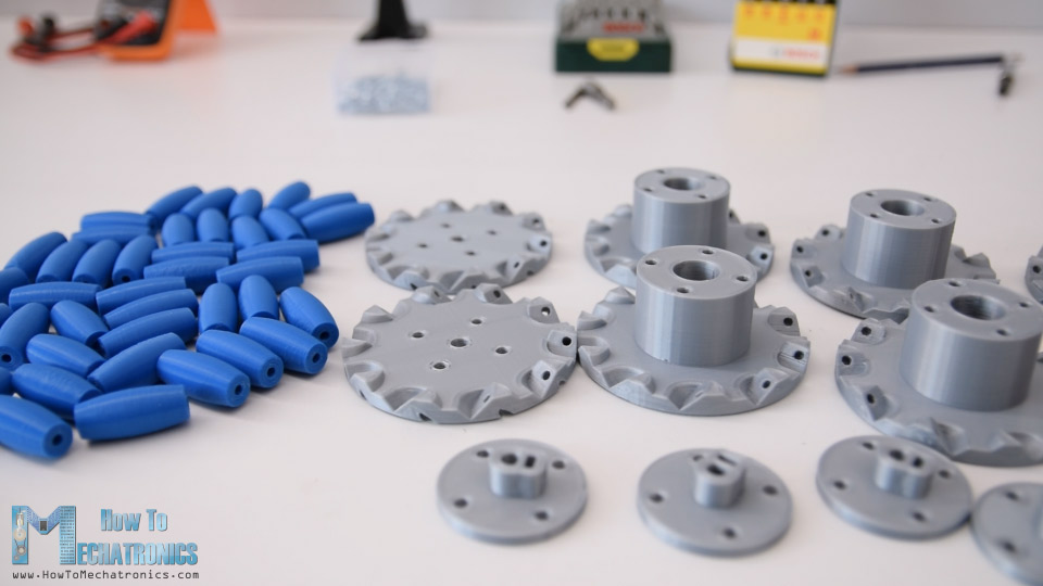
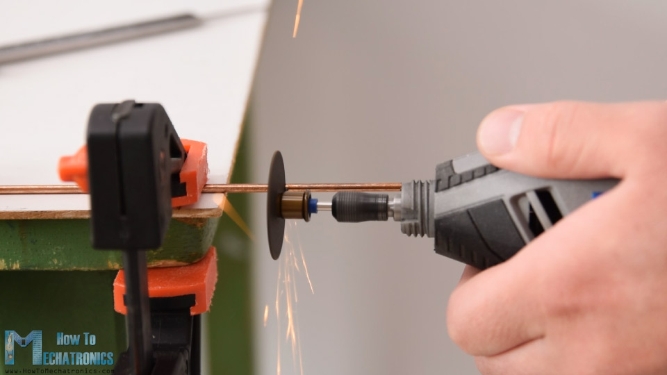
So, once I got the 3D printed parts ready, I moved on with making the shafts for the rollers. For that purpose, I used 3 mm tick steel wire. The length of the shafts needs to be around 40mm, so using a rotary tool I cut the wire to that length.
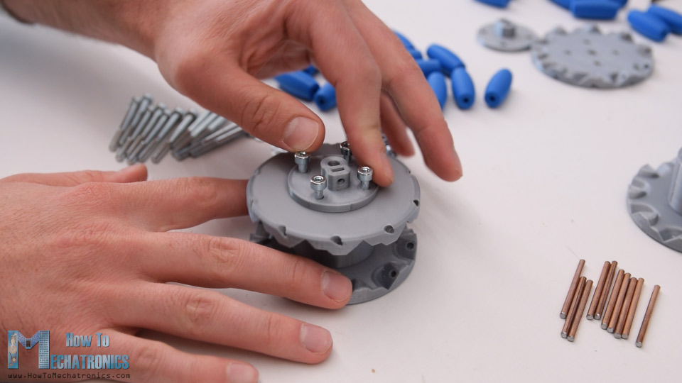
I started assembling the Mecanum wheel by securing the two sides and the shaft coupler using four M4 bolts and nuts. The length of the bolts needs to be 45mm.
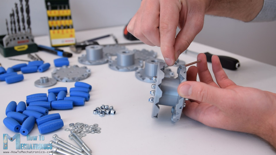
For installing the rollers, first we need to slightly insert the shaft through the holes located at the circumference of the inner side.
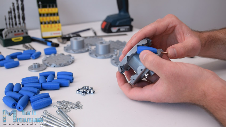
Then we can insert a small M3 washer, insert the roller and push the shaft all the way to into the slot of the outer side of the wheel. I used a single washer because I didn’t have enough space to insert a second washer on the other side.
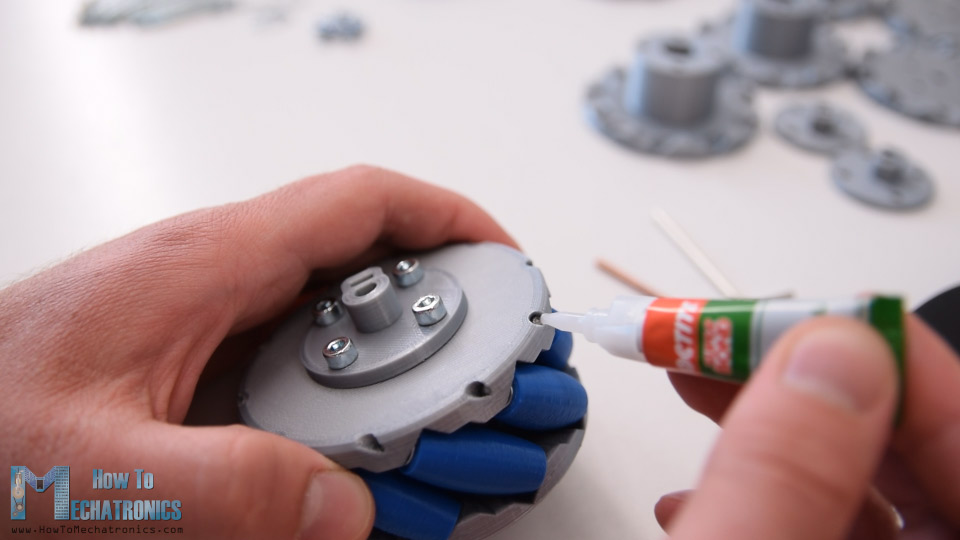
I repeated this process for all 10 rollers. It’s actually easy and kind of fun assembling these wheels. What’s important here is that the rollers need to be able to move freely.
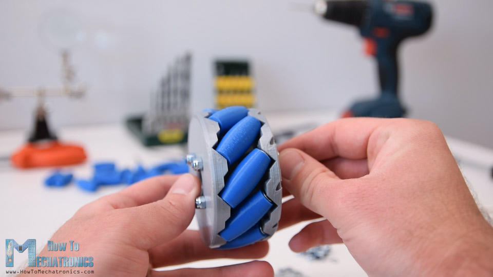
At the end I used few drops of AC glue in each of the inner holes to make sure that shafts won’t get loose.
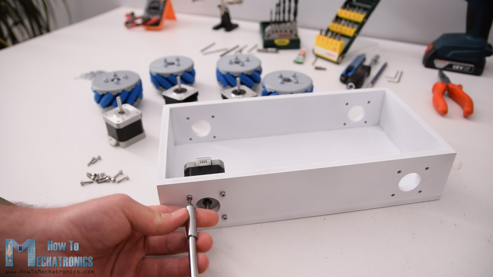
Ok so once the wheels are ready now we can move on with assembling the whole robot. First, we need to attach the stepper motors to the base platform. For securing them in place I used M3 bolts with a length of 12mm.
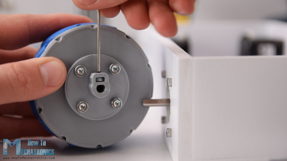
Next, we need to attach the wheels to the motor’s shafts. The shaft coupler that I made have a slot for inserting an M3 nut, through which an M3 bolts can pass through and so we can secure the wheel to the shaft.
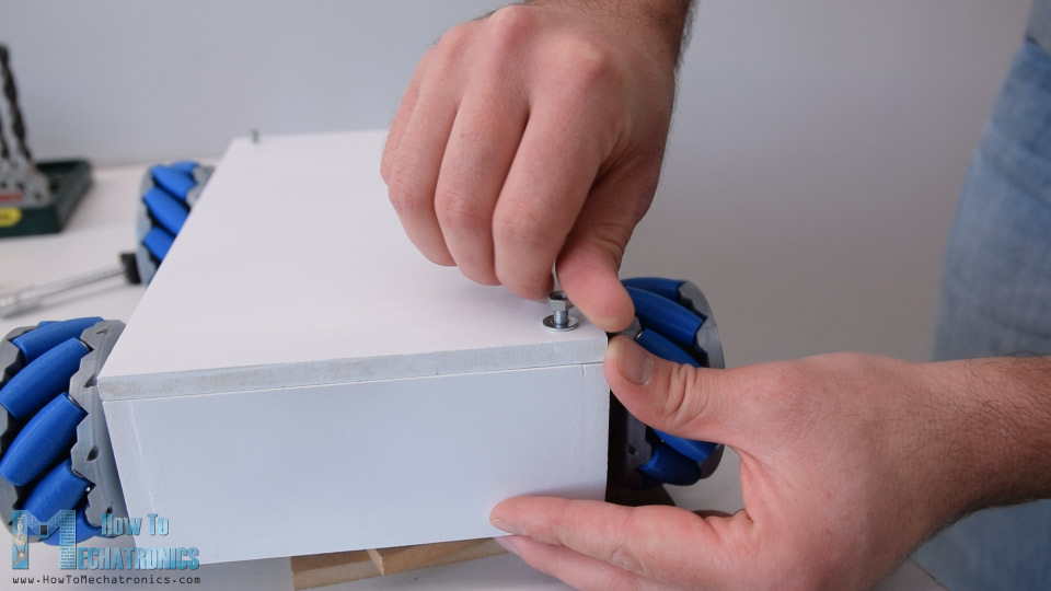
Next, for securing the top cover to the base, I attached threaded rods on two corners of the base. I made holes on the same position on the cover and so I was able to easy insert and secure the cover to the base.
On the back side of the base I made 20mm hole for attaching a power switch later on, as well as a 5mm hole for attaching an LED.
Circuit Diagram
Now we can move on with the electronics. Here’s the complete circuit diagram of this project.
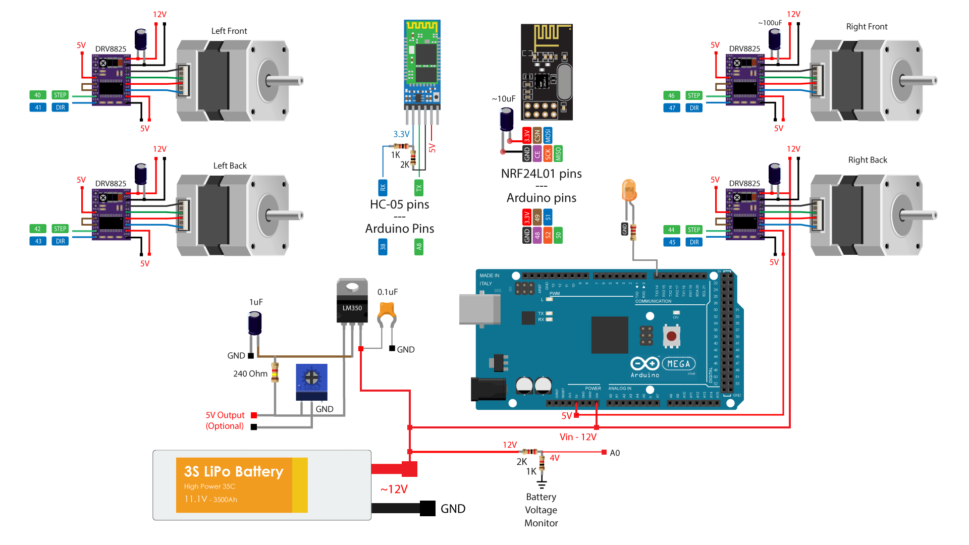
So we will control the four NEMA 17 stepper motors using four DRV8825 stepper drivers, or also we could use the A4988 stepper drivers. For powering the steppers and the whole robot we will use 12V power supply, and in my case, I will use a 3S Li-Po battery which provides around 12V. For the radio communication we are using the NRF24L01 module, and for the Bluetooth communication we are using the HC-05 Bluetooth module. I also included a simple voltage divider which will be used for monitoring the battery voltage and an LED connection for indicating when the battery voltage will drop below 11V.
I also included a dedicated 5V voltage regulator which can provide around 3A of current. This is optional, but I’m planning in a future video to combine this project with my Arduino Robot Arm project, and for that purpose I would need 5V for driving its servo motors.
You can get the components needed for this project from the links below:
- Stepper Motor – NEMA 17……………… Amazon / Banggood / AliExpress
- DRV8825 Stepper Driver………………… Amazon / Banggood / AliExpress
- NRF24L01 Transceiver Module…….… Amazon / Banggood / AliExpress
- HC-05 Bluetooth Module …………….… Amazon / Banggood / AliExpress
- Li-Po battery …………………………….…… Amazon / Banggood / AliExpress
- Arduino Mega Board ………………….… Amazon / Banggood / AliExpress
Disclosure: These are affiliate links. As an Amazon Associate I earn from qualifying purchases.
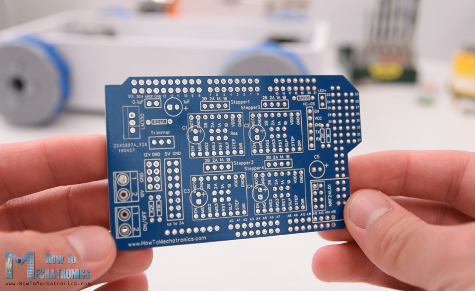
PCB Design
Nevertheless, in order to keep the electronics components organized and get rid of the wiring mess, I designed a custom PCB using the EasyEDA free online circuit design software. This PCB will actually act as an Arduino MEGA shield because we will be able to directly connect it on top of the Arduino Mega board. I used both the top and the bottom layer for running the connections. For those Arduno pins which I didn’t use, I included pin header connections so that they are available in case we want to use them for something in future. I also included 12V, 5V and GND connection pins, as well as pins for selecting the stepping resolution of the drivers.
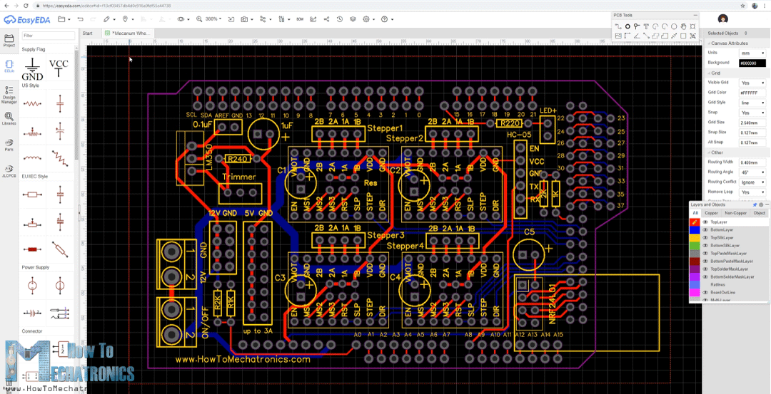
Here’s a link to the project files of this PCB design. So once I finished the design, I generated the Gerber file needed for manufacturing the PCB.
Gerber file:
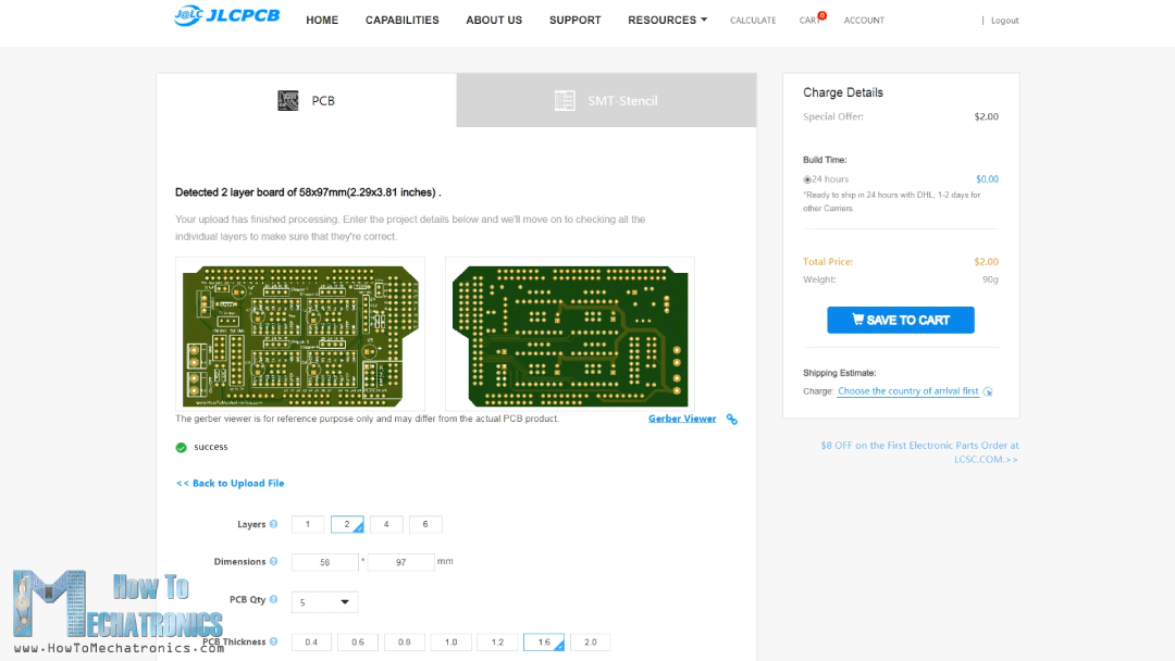
Then I ordered the PCB from JLCPCB which are also the sponsor of this video.
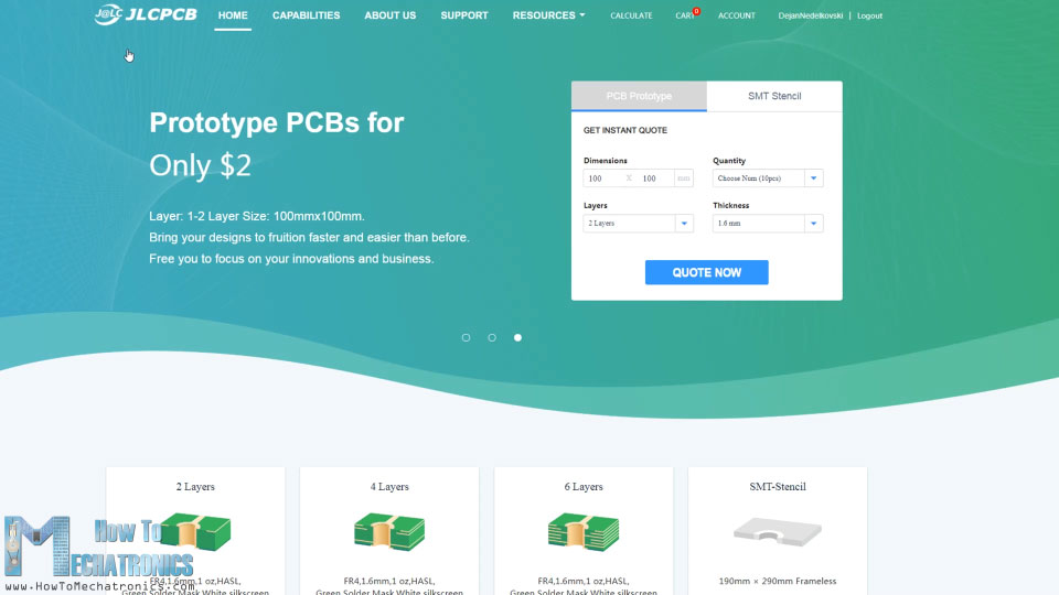
Here we can simply drag and drop the Gerber file and once uploaded, we can review our PCB in the Gerber viewer. If everything is all right then we can go on and select the properties that we want for our PCB. This time I chose the PCB color to be blue in order to match with the Arduino board color. And that’s it, now we can simply order our PCB at a reasonable price. Note that if it’s your first order from JLCPCB, you can get up to 10 PCBs for only $2.
After several days the PCBs have arrived. The quality of the PCBs is great and everything is exactly the same as in the design.
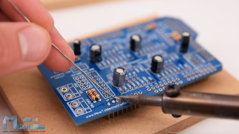
Assembling the PCB
Ok now we can move on and assemble the PCB. I started with soldering the smaller components first, the resistors and the capacitors. Then I inserted and soldered male pin headers to the PCB which will be used for connecting it to the Arduino board.
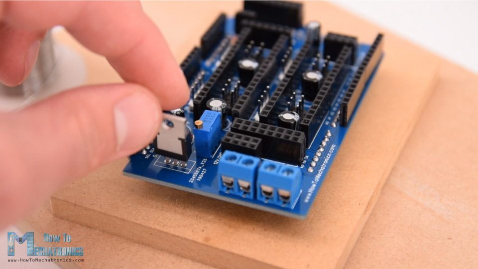
Next, I placed all female pin headers in place and soldered them as well. As for the stepper motors connections and pins for selecting the stepping resolution I used male pin headers. This way we can directly connect the motors to the PCB and use jumpers for selecting the stepping resolution. Then I soldered the terminal blocks, the trimmer and the voltage regulator.
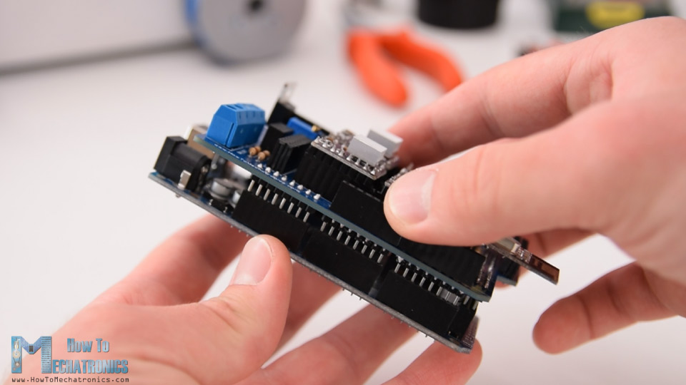
And that’s it, the PCB is now ready and we can move on with inserting the drivers and connecting the motors to it. First, I placed the jumpers for selecting the stepping resolution. I selected 16th step resolution by connecting the MS3 pins of the drivers to 5V.
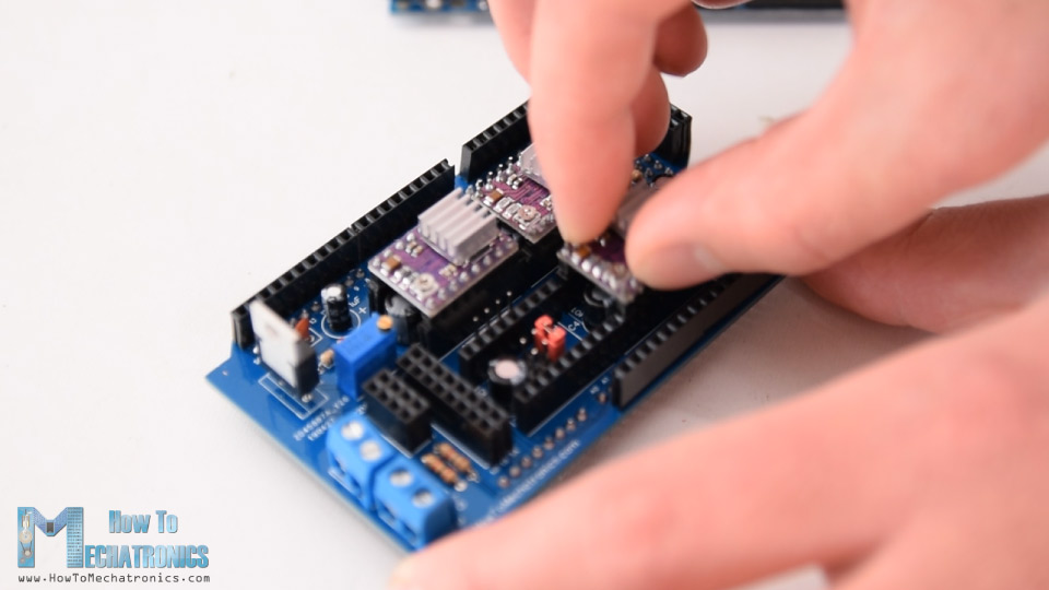
Then on top of them I placed the DRV8825 drivers, as well as, connected the NRF24L01 module and the HC-05 Bluetooth module. Now we can simple attach the PCB to the Arduno board.
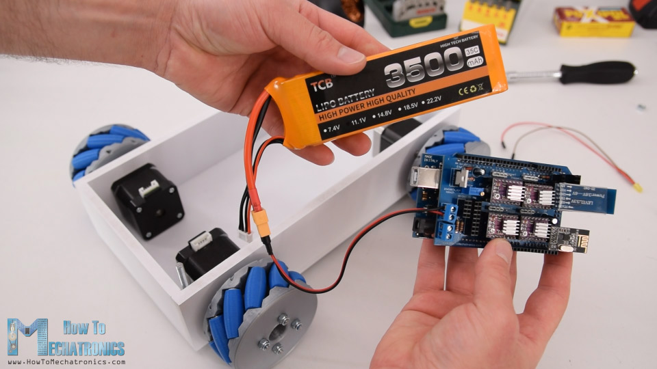
Next, I connected the battery to the appropriate terminal block and placed them into the base platform.
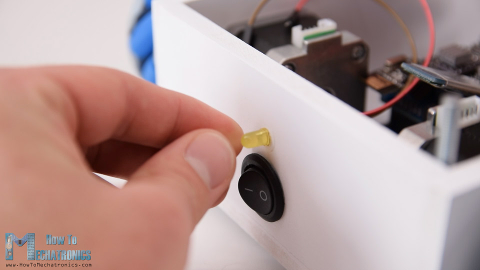
Here I inserted the power switch in place and connected it to the other terminal block. Right above the power switch I also inserted the battery indicator LED.
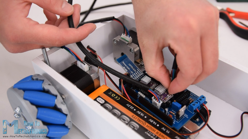
What’s left now is to connect the motors to the PCB. We should note here that when connecting opposite motors, we should connect their connectors opposite as well. This is needed later when programming the robot, so that, for example, the forward command, would move both motors in same direction, although they are actually flipped and one would make clockwise and the other anticlockwise rotation.
At the end I can simple insert the cover at the top, and so we are done with this Mecanum Wheels robot project.
Mecanum Wheels Robot Arduino Code
What’s left for this video is to take a look at the Arduino code. Actually, there are two separate Arduino codes. This one is for controlling the robot using the NRF24L01 modules and other is for controlling to robot using a smartphone.
Arduino code for controlling the robot using the NRF24L01 modules:
/*
   === Arduino Mecanum Wheels Robot ===
     Radio control with NRF24L01
  by Dejan, www.HowToMechatronics.com
  Libraries:
  RF24, https://github.com/tmrh20/RF24/
  AccelStepper by Mike McCauley: http://www.airspayce.com/mikem/arduino/AccelStepper/index.html

*/

#include <SPI.h>
#include <nRF24L01.h>
#include <RF24.h>

#include <AccelStepper.h>

RF24 radio(48, 49);   // nRF24L01 (CE, CSN)

const byte address[6] = "00001";
unsigned long lastReceiveTime = 0;
unsigned long currentTime = 0;

// Define the stepper motors and the pins the will use
AccelStepper LeftBackWheel(1, 42, 43);   // (Type:driver, STEP, DIR) - Stepper1
AccelStepper LeftFrontWheel(1, 40, 41);  // Stepper2
AccelStepper RightBackWheel(1, 44, 45);  // Stepper3
AccelStepper RightFrontWheel(1, 46, 47); // Stepper4

int wheelSpeed = 1500;

// Max size of this struct is 32 bytes - NRF24L01 buffer limit
struct Data_Package {
  byte j1PotX;
  byte j1PotY;
  byte j1Button;
  byte j2PotX;
  byte j2PotY;
  byte j2Button;
  byte pot1;
  byte pot2;
  byte tSwitch1;
  byte tSwitch2;
  byte button1;
  byte button2;
  byte button3;
  byte button4;
};
Data_Package data; //Create a variable with the above structure

void setup() {
  // Set initial seed values for the steppers
  LeftFrontWheel.setMaxSpeed(3000);
  LeftBackWheel.setMaxSpeed(3000);
  RightFrontWheel.setMaxSpeed(3000);
  RightBackWheel.setMaxSpeed(3000);

  radio.begin();
  radio.openReadingPipe(0, address);
  radio.setAutoAck(false);
  radio.setDataRate(RF24_250KBPS);
  radio.setPALevel(RF24_PA_LOW);
  radio.startListening(); //  Set the module as receiver

  Serial.begin(115200);
}

void loop() {
  // Check whether we keep receving data, or we have a connection between the two modules
  currentTime = millis();
  if ( currentTime - lastReceiveTime > 1000 ) { // If current time is more then 1 second since we have recived the last data, that means we have lost connection
    resetData(); // If connection is lost, reset the data. It prevents unwanted behavior, for example if a drone jas a throttle up, if we lose connection it can keep flying away if we dont reset the function
  }
  // Check whether there is data to be received
  if (radio.available()) {
    radio.read(&data, sizeof(Data_Package)); // Read the whole data and store it into the 'data' structure
    lastReceiveTime = millis(); // At this moment we have received the data
  }
  // Set speed - left potentiometer
  wheelSpeed = map(data.pot1, 0, 255, 100, 3000);

  if (data.j1PotX > 150) {
    moveSidewaysLeft();
  }
  else if (data.j1PotX < 100) {
    moveSidewaysRight();
  }
  else if (data.j1PotY > 160) {
    moveForward();
  }
  else if (data.j1PotY < 100) {
    moveBackward();
  }
  else if (data.j2PotX < 100 & data.j2PotY > 160) {
    moveRightForward();
  }
  else if (data.j2PotX > 160 & data.j2PotY > 160) {
    moveLeftForward();
  }
  else if (data.j2PotX < 100 & data.j2PotY < 100) {
    moveRightBackward();
  }
  else if (data.j2PotX > 160 & data.j2PotY < 100) {
    moveLeftBackward();
  }
  else if (data.j2PotX < 100) {
    rotateRight();
  }
  else if (data.j2PotX > 150) {
    rotateLeft();
  }
  else {
    stopMoving();
  }
  // Execute the steps
  LeftFrontWheel.runSpeed();
  LeftBackWheel.runSpeed();
  RightFrontWheel.runSpeed();
  RightBackWheel.runSpeed();

  // Monitor the battery voltage
  int sensorValue = analogRead(A0);
  float voltage = sensorValue * (5.0 / 1023.00) * 3; // Convert the reading values from 5v to suitable 12V i
  // If voltage is below 11V turn on the LED
  if (voltage < 11) {
    digitalWrite(led, HIGH);
  }
  else {
    digitalWrite(led, LOW);
  }
}

void moveForward() {
  LeftFrontWheel.setSpeed(wheelSpeed);
  LeftBackWheel.setSpeed(wheelSpeed);
  RightFrontWheel.setSpeed(wheelSpeed);
  RightBackWheel.setSpeed(wheelSpeed);
}
void moveBackward() {
  LeftFrontWheel.setSpeed(-wheelSpeed);
  LeftBackWheel.setSpeed(-wheelSpeed);
  RightFrontWheel.setSpeed(-wheelSpeed);
  RightBackWheel.setSpeed(-wheelSpeed);
}
void moveSidewaysRight() {
  LeftFrontWheel.setSpeed(wheelSpeed);
  LeftBackWheel.setSpeed(-wheelSpeed);
  RightFrontWheel.setSpeed(-wheelSpeed);
  RightBackWheel.setSpeed(wheelSpeed);
}
void moveSidewaysLeft() {
  LeftFrontWheel.setSpeed(-wheelSpeed);
  LeftBackWheel.setSpeed(wheelSpeed);
  RightFrontWheel.setSpeed(wheelSpeed);
  RightBackWheel.setSpeed(-wheelSpeed);
}
void rotateLeft() {
  LeftFrontWheel.setSpeed(-wheelSpeed);
  LeftBackWheel.setSpeed(-wheelSpeed);
  RightFrontWheel.setSpeed(wheelSpeed);
  RightBackWheel.setSpeed(wheelSpeed);
}
void rotateRight() {
  LeftFrontWheel.setSpeed(wheelSpeed);
  LeftBackWheel.setSpeed(wheelSpeed);
  RightFrontWheel.setSpeed(-wheelSpeed);
  RightBackWheel.setSpeed(-wheelSpeed);
}
void moveRightForward() {
  LeftFrontWheel.setSpeed(wheelSpeed);
  LeftBackWheel.setSpeed(0);
  RightFrontWheel.setSpeed(0);
  RightBackWheel.setSpeed(wheelSpeed);
}
void moveRightBackward() {
  LeftFrontWheel.setSpeed(0);
  LeftBackWheel.setSpeed(-wheelSpeed);
  RightFrontWheel.setSpeed(-wheelSpeed);
  RightBackWheel.setSpeed(0);
}
void moveLeftForward() {
  LeftFrontWheel.setSpeed(0);
  LeftBackWheel.setSpeed(wheelSpeed);
  RightFrontWheel.setSpeed(wheelSpeed);
  RightBackWheel.setSpeed(0);
}
void moveLeftBackward() {
  LeftFrontWheel.setSpeed(-wheelSpeed);
  LeftBackWheel.setSpeed(0);
  RightFrontWheel.setSpeed(0);
  RightBackWheel.setSpeed(-wheelSpeed);
}
void stopMoving() {
  LeftFrontWheel.setSpeed(0);
  LeftBackWheel.setSpeed(0);
  RightFrontWheel.setSpeed(0);
  RightBackWheel.setSpeed(0);
}


void resetData() {
  // Reset the values when there is no radio connection - Set initial default values
  data.j1PotX = 127;
  data.j1PotY = 127;
  data.j2PotX = 127;
  data.j2PotY = 127;
  data.j1Button = 1;
  data.j2Button = 1;
  data.pot1 = 1;
  data.pot2 = 1;
  data.tSwitch1 = 1;
  data.tSwitch2 = 1;
  data.button1 = 1;
  data.button2 = 1;
  data.button3 = 1;
  data.button4 = 1;
}Code language: PHP (php)
Descripton: So, here we are using the RF24 library for the radio communication and the AccelStepper library for controlling the stepper motors. First we need to define the pins to which all of them are connected, define some variables needed for the program below, and in the setup section set the steppers maximum speed and begin the radio communication.
In the loop section we start by reading the data coming from the RC transmitter. The RC transmitter code as well as more details how this communication works can be found on my particular tutorial for it.
So depending on the received data, for example, if the left Joystick is moved forward, its value will be greater than 160 and in such a case will call the moveForward() custom function. If we taka a look at this function we can see that all it does is it sets the speed of the motors to positive. For moving backward, the speed is set to negative. So for moving in all other directions we just have to set the rotations of the wheels appropriately as explained in the beginning.
For executing these commands, in the loop section we need to call the runSpeed() functions for all steppers. In the loop section we also read the analog input from the voltage divider coming from the battery, and according to this value we can know when the battery voltage will drop under 11V so we can turn on the indicating LED.
Arduino code for controlling to robot using a smartphone:
/*
=== Arduino Mecanum Wheels Robot ===
Smartphone control via Bluetooth
by Dejan, www.HowToMechatronics.com
Libraries:
RF24, https://github.com/tmrh20/RF24/
AccelStepper by Mike McCauley: http://www.airspayce.com/mikem/arduino/AccelStepper/index.html
*/
#include <SoftwareSerial.h>
#include <AccelStepper.h>
SoftwareSerial Bluetooth(A8, 38); // Arduino(RX, TX) - HC-05 Bluetooth (TX, RX)
// Define the stepper motors and the pins the will use
AccelStepper LeftBackWheel(1, 42, 43); // (Type:driver, STEP, DIR) - Stepper1
AccelStepper LeftFrontWheel(1, 40, 41); // Stepper2
AccelStepper RightBackWheel(1, 44, 45); // Stepper3
AccelStepper RightFrontWheel(1, 46, 47); // Stepper4
#define led 14
int wheelSpeed = 1500;
int dataIn, m;
int lbw[50], lfw[50], rbw[50], rfw[50]; // for storing positions/steps
int index = 0;
void setup() {
// Set initial seed values for the steppers
LeftFrontWheel.setMaxSpeed(3000);
LeftBackWheel.setMaxSpeed(3000);
RightFrontWheel.setMaxSpeed(3000);
RightBackWheel.setMaxSpeed(3000);
Serial.begin(38400);
Bluetooth.begin(38400); // Default baud rate of the Bluetooth module
Bluetooth.setTimeout(1);
delay(20);
pinMode(led, OUTPUT);
}
void loop() {
// Check for incoming data
if (Bluetooth.available() > 0) {
dataIn = Bluetooth.read(); // Read the data
if (dataIn == 0) {
m = 0;
}
if (dataIn == 1) {
m = 1;
}
if (dataIn == 2) {
m = 2;
}
if (dataIn == 3) {
m = 3;
}
if (dataIn == 4) {
m = 4;
}
if (dataIn == 5) {
m = 5;
}
if (dataIn == 6) {
m = 6;
}
if (dataIn == 7) {
m = 7;
}
if (dataIn == 8) {
m = 8;
}
if (dataIn == 9) {
m = 9;
}
if (dataIn == 10) {
m = 10;
}
if (dataIn == 11) {
m = 11;
}
if (dataIn == 12) {
m = 12;
}
if (dataIn == 14) {
m = 14;
}
// Set speed
if (dataIn >= 16) {
wheelSpeed = dataIn * 10;
Serial.println(wheelSpeed);
}
}
if (m == 4) {
moveSidewaysLeft();
}
if (m == 5) {
moveSidewaysRight();
}
if (m == 2) {
moveForward();
}
if (m == 7) {
moveBackward();
}
if (m == 3) {
moveRightForward();
}
if (m == 1) {
moveLeftForward();
}
if (m == 8) {
moveRightBackward();
}
if (m == 6) {
moveLeftBackward();
}
if (m == 9) {
rotateLeft();
}
if (m == 10) {
rotateRight();
}
if (m == 0) {
stopMoving();
}
//Serial.println(dataIn);
// If button "SAVE" is pressed
if (m == 12) {
if (index == 0) {
LeftBackWheel.setCurrentPosition(0);
LeftFrontWheel.setCurrentPosition(0);
RightBackWheel.setCurrentPosition(0);
RightFrontWheel.setCurrentPosition(0);
}
lbw[index] = LeftBackWheel.currentPosition(); // save position into the array
lfw[index] = LeftFrontWheel.currentPosition();
rbw[index] = RightBackWheel.currentPosition();
rfw[index] = RightFrontWheel.currentPosition();
index++; // Increase the array index
m = 0;
}
if (m == 14) {
runSteps();
if (dataIn != 14) {
stopMoving();
memset(lbw, 0, sizeof(lbw)); // Clear the array data to 0
memset(lfw, 0, sizeof(lfw));
memset(rbw, 0, sizeof(rbw));
memset(rfw, 0, sizeof(rfw));
index = 0; // Index to 0
}
}
LeftFrontWheel.runSpeed();
LeftBackWheel.runSpeed();
RightFrontWheel.runSpeed();
RightBackWheel.runSpeed();
// Monitor the battery voltage
int sensorValue = analogRead(A0);
float voltage = sensorValue * (5.0 / 1023.00) * 3; // Convert the reading values from 5v to suitable 12V i
//Serial.println(voltage);
// If voltage is below 11V turn on the LED
if (voltage < 11) {
digitalWrite(led, HIGH);
}
else {
digitalWrite(led, LOW);
}
}
void runSteps() {
for (int i = index - 1; i >= 0; i--) { // Run through all steps(index)
LeftFrontWheel.moveTo(lfw[i]);
LeftFrontWheel.setSpeed(wheelSpeed);
LeftBackWheel.moveTo(lbw[i]);
LeftBackWheel.setSpeed(wheelSpeed);
RightFrontWheel.moveTo(rfw[i]);
RightFrontWheel.setSpeed(wheelSpeed);
RightBackWheel.moveTo(rbw[i]);
RightBackWheel.setSpeed(wheelSpeed);
while (LeftBackWheel.currentPosition() != lbw[i] & LeftFrontWheel.currentPosition() != lfw[i] & RightFrontWheel.currentPosition() != rfw[i] & RightBackWheel.currentPosition() != rbw[i]) {
LeftFrontWheel.runSpeedToPosition();
LeftBackWheel.runSpeedToPosition();
RightFrontWheel.runSpeedToPosition();
RightBackWheel.runSpeedToPosition();
if (Bluetooth.available() > 0) { // Check for incomding data
dataIn = Bluetooth.read();
if ( dataIn == 15) { // If button "PAUSE" is pressed
while (dataIn != 14) { // Wait until "RUN" is pressed again
if (Bluetooth.available() > 0) {
dataIn = Bluetooth.read();
if ( dataIn == 13) {
stopMoving();
break;
}
}
}
}
if (dataIn >= 16) {
wheelSpeed = dataIn * 10;
dataIn = 14;
}
if ( dataIn == 13) {
break;
}
}
}
}
// Go back through steps
for (int i = 1; i <= index - 1; i++) { // Run through all steps(index)
LeftFrontWheel.moveTo(lfw[i]);
LeftFrontWheel.setSpeed(wheelSpeed);
LeftBackWheel.moveTo(lbw[i]);
LeftBackWheel.setSpeed(wheelSpeed);
RightFrontWheel.moveTo(rfw[i]);
RightFrontWheel.setSpeed(wheelSpeed);
RightBackWheel.moveTo(rbw[i]);
RightBackWheel.setSpeed(wheelSpeed);
while (LeftBackWheel.currentPosition() != lbw[i]& LeftFrontWheel.currentPosition() != lfw[i] & RightFrontWheel.currentPosition() != rfw[i] & RightBackWheel.currentPosition() != rbw[i]) {
LeftFrontWheel.runSpeedToPosition();
LeftBackWheel.runSpeedToPosition();
RightFrontWheel.runSpeedToPosition();
RightBackWheel.runSpeedToPosition();
//Serial.print(" current: ");
//Serial.println(LeftBackWheel.currentPosition());
if (Bluetooth.available() > 0) { // Check for incomding data
dataIn = Bluetooth.read();
if ( dataIn == 15) { // If button "PAUSE" is pressed
while (dataIn != 14) { // Wait until "RUN" is pressed again
if (Bluetooth.available() > 0) {
dataIn = Bluetooth.read();
if ( dataIn == 13) {
stopMoving();
break;
}
}
}
}
if (dataIn >= 16) {
wheelSpeed = dataIn * 10;
dataIn = 14;
}
if ( dataIn == 13) {
//Serial.println("DEKI");
break;
}
}
}
}
}
void moveForward() {
LeftFrontWheel.setSpeed(wheelSpeed);
LeftBackWheel.setSpeed(wheelSpeed);
RightFrontWheel.setSpeed(wheelSpeed);
RightBackWheel.setSpeed(wheelSpeed);
}
void moveBackward() {
LeftFrontWheel.setSpeed(-wheelSpeed);
LeftBackWheel.setSpeed(-wheelSpeed);
RightFrontWheel.setSpeed(-wheelSpeed);
RightBackWheel.setSpeed(-wheelSpeed);
}
void moveSidewaysRight() {
LeftFrontWheel.setSpeed(wheelSpeed);
LeftBackWheel.setSpeed(-wheelSpeed);
RightFrontWheel.setSpeed(-wheelSpeed);
RightBackWheel.setSpeed(wheelSpeed);
}
void moveSidewaysLeft() {
LeftFrontWheel.setSpeed(-wheelSpeed);
LeftBackWheel.setSpeed(wheelSpeed);
RightFrontWheel.setSpeed(wheelSpeed);
RightBackWheel.setSpeed(-wheelSpeed);
}
void rotateLeft() {
LeftFrontWheel.setSpeed(-wheelSpeed);
LeftBackWheel.setSpeed(-wheelSpeed);
RightFrontWheel.setSpeed(wheelSpeed);
RightBackWheel.setSpeed(wheelSpeed);
}
void rotateRight() {
LeftFrontWheel.setSpeed(wheelSpeed);
LeftBackWheel.setSpeed(wheelSpeed);
RightFrontWheel.setSpeed(-wheelSpeed);
RightBackWheel.setSpeed(-wheelSpeed);
}
void moveRightForward() {
LeftFrontWheel.setSpeed(wheelSpeed);
LeftBackWheel.setSpeed(0);
RightFrontWheel.setSpeed(0);
RightBackWheel.setSpeed(wheelSpeed);
}
void moveRightBackward() {
LeftFrontWheel.setSpeed(0);
LeftBackWheel.setSpeed(-wheelSpeed);
RightFrontWheel.setSpeed(-wheelSpeed);
RightBackWheel.setSpeed(0);
}
void moveLeftForward() {
LeftFrontWheel.setSpeed(0);
LeftBackWheel.setSpeed(wheelSpeed);
RightFrontWheel.setSpeed(wheelSpeed);
RightBackWheel.setSpeed(0);
}
void moveLeftBackward() {
LeftFrontWheel.setSpeed(-wheelSpeed);
LeftBackWheel.setSpeed(0);
RightFrontWheel.setSpeed(0);
RightBackWheel.setSpeed(-wheelSpeed);
}
void stopMoving() {
LeftFrontWheel.setSpeed(0);
LeftBackWheel.setSpeed(0);
RightFrontWheel.setSpeed(0);
RightBackWheel.setSpeed(0);
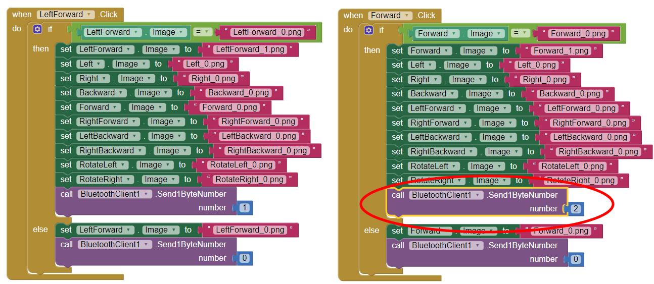
}Code language: PHP (php)Description: The other code for controlling the robot using the Android application, is very similar and works the same way. Here instead of the radio module we need to define the Bluetooth module and initialize its communication in the setup section. So again, first we read the incoming data from the smartphone or the Android app, and according to it, tell the robot in which direction to move.
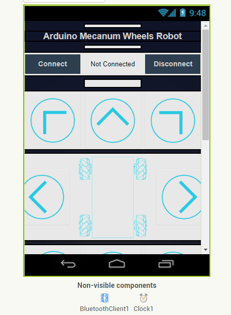
If we take a look at the Android app we can see that it simply sends numbers from 0 to 15 through the Bluetooth when the buttons are pressed.
The app is made using the MIT App Inventor online application and you can find more details about it in my particular tutorial for it.
Here you can download this app as well as the editable project file:
For programming the automatic robot movement with this app, when we press the “SAVE” button we simply store the current positions of the stepper motors into arrays. Then when we press the “RUN” button, we call the runSteps() custom function which executes or runs through all stored steps using some for and while loops.
I hope you enjoyed this tutorial and learned something new. Feel free to ask any question in the comments section below and check my Arduino Projects Collection.
I cannot download the app file. it gives me invalid file.
Please try again, it should work now. Clear your web-browser cache first though. Cheers!
Hi Dejan,
Great project! I am currently working on a school project where me and a friend are building a robot that will have mecanum wheels and I was wondering if it would be ok to use your CAD-files to print our own wheels?
I felt it was best to ask since I am not sure if this counts as open source, we will of course cite you and the website in the report.
Hi, thanks! Sure you can use the CAD files for school projects.
would it be possible to use the TMC2208s instead of the DRV885s. i have a few of them so i thought they might work. looks like they have the same pinouts.
thank you
Gary
The TMC22088s are very similar, but they have different microstepping resolution selecting pins, plus the EN pin should be put to GND and the RST and SLP pins doesn’t need to be connected to each other like for the DRV8825 driver. So you will need to make that slight adjustment to the PCB in order to have them working.
Hi Dejan,
Very nice project. I’m trying to do something similar but with DC motors instead of stepper motors. How can I change the code to implement this?
Thanks
Hey,
Thanks! Well making this project with DC motors instead of steppers would mean completely different code. To code will depend from the DC motors and it’s drivers.
Hi Dejan,
Can you help me a second time?
I’m trying to send data via Bluetooth to the HC-05. I get data for n the module but they are quit different from that, what I send.
Example: I send a “1” and the serial monitor in the Arduino IDE shows me 120 (or 128, I don’t know exactly).
Solved: I used the wrong baud rate…
Hi Dejan,
it looks so complicated but the solution is so easy –> that is engineering par excellence! Great job.
One question:
I can’t get the size of the trimmer resistor near the LM350 to manage the 5V. Can you tell me the type and the size of it?
Thanks
Hey, thanks!
I used the following trimmer: 3296W-1-103
The tutorial was excellent. Have you considered adding a top down photo of the pcb board after it is soldered and before the motor drivers are added. It would help beginners determine where male and female headers are in design and give something to reference. I worked it out but a photo could have made me more comfortable when soldering it all together.
Hi, i’m currently working on a similar project but i want to add an engraving laser to the vehicle. Would your pcb be adecuate for the job and still be compatible with a software that sends the instructions in gcode to work like a cnc or would it be easier to use a generic shield ramps 1.4 and figure out how to use 2 step motors for each x and y axis?
Hey, is such a case I guess it would be better to go for the generic shield.
Are there tolerances for the resistors in the project? Specifically I can’t find 2k resistors. I can get 1.8k, 2.2k or 2.7K.
You can use two 1K resistors connected in series to get the 2k resistance.
Hello Dejan,
Thank you for the amazing project! Is a 2800 mah 11.1V 3s Lipo Battery enough for the mecanum wheels?
Hi, what type of plastic you use for rotating parts of wheels (blue parts)? TPU, PLA?
Thank you in advance!
I used PLA but TPU would be a good choice as well.
Hy Dejan, thanks a lot for sharing.
I wanted to use stronger motors like the Nema 23, which have a shaft slightly bigger, i wanted to change size of the shaft coupler, I use solid works, but the mecanum wheels file come as a full assembly, which I can’t find a SLDP of the wheel parts.
can you help me with that, is there a specific sip file with all the parts?
Hey, I think you should be able to modify the shaft coupler part even with the .step file.
Briefly, I need a 3D model (SLDPRT files)
Hey, I would like first to thank you for this tutorial and the kind of learning material you are offering in here for “free”. I need download Mecanum Wheels Robot 3D Model STEP file but Download Limit Exceeded!
Hey, try using different web browser, clear cache, try incognito or from your smartphone.
hi, i have same problem , i try on phone, on difffrent browser and still cant download.
Hey, I actually fixed it now. It was really a download limit problem, the file was downloaded 5000 times which is the default download limit for the file. Now I increased it so you can go ahead and download it. Sorry for the about it.
Hey, I need the Mecanum Wheels robot 3D Model – SOLIDWORKS Files Include all parts and assembly of Mecanum Wheels robot. I tried to download the Mecanum Wheels Robot 3D Model STEP file but this not valid and nor zipped file.
Briefly, I need a 3D model (SLDPRT files)
Hello, I love Your projects really great and informative! It’s really great to see electronics from all aspects, how an idea becomes a great project.
I am a electronics enthusiast (begginer) and had a little problem trying to build this project for myself. So I am using drv8825 and everything works just fine except when the stepper get STOP signal (m=0) it moves at full speed instead of not moving. I checked Bluetooth it works fine (gets all the correct signals), and I can see that it works because everything is working just fine. The steppers are moving at the given speed in the given direction when they have to, but when they don’t have to move they rotate at full speed. Maybe You would know the cause of this? (I am using everything like in the tutorial except I haven’t connected the RF module, cause i lost it :D).
Hey, thanks! Well that’s a bit strange. You see, if “m=0” we call the stopMoving() custom functions which sets the motors speeds to 0 and that stops the motor moving. What I can think the problem could be is that your are not receiving the correct data for stopping from the control app. Make sure you receive “0” from the “dataIn” variable and the “m” variable gets the value 0.
Hello there.
I have been studying your project for a long time, I can’t wait to do it.
I read all the comments and decided to do it with the cnc shield in my hand.
I have a question if I use A4988 instead of drv8825, would the code be appropriate? Thank you.
Both drivers are controlled the same way, there is no difference in the codes or anything.
Hello..i am currently building this project..can i know the importance of the trimmer in the circuitry? Thanks
The trimmer is used for getting the 12v from the battery to 5V output in case you need to drive something that requires 5V. In this case, for the Mecanum Wheels Robot we don’t really need that, so you can ignore it. I added that feature in the PCB for the updated version of this projects, where I attached the robot arm from my previous projets, which uses 5V servo motors.
I did this project exactly what you have told, but I used a CNC shield instead of custom board for the drives. And also I added ultrasonic sonic sensors and magneto-meter for obstacle avoidance and degree of movement. I am using this project for my degree final year major project. For the application-oriented, I am using a sensor hub (To check free slots in parking lot) with the help of Arduino & Bluetooth in parking lot to give instructions to the robot to pick and place cars.
Thank you very much for making this project. I loved it.
Now I like to make some patterns (like circles, shapes or simple drawings with crayons). Is it possible to do that, at least circles (like DJI robomaster s1 robot do)? Is there any software to give instructions to the robot to make patterns or drawings?
Can you please help me to do what I like to do?
Thank you once again for your wonderful instructions for making this robot possible.
Hey, glad to hear it! Well I guess you should make the program for making such patters. Try first with simple shapes, like drawing a rectangle, then a hexagon, and get to circle :).
hey man
i am building this project. its almost complete according to your directions, but the motors dont seem to show any movement [tested separately motors are working fine] , when the motors were tested separately the FAULT pin of DRV8825 was not given any voltage. in your project all the FAULT pins are given 5v from arduino. Can you give the reason of doing so , and any idea about why my project isnt working. how should i go about troubleshooting my project
Hey, the FAULT pin is fine even when given 5V from the Arduino. The reason it’s made like that is because the A4988 driver on that place has the VCC pin, so in this way you can use both the A4988 or the DRV8825 driver. Try to use simpler example/code to move the motors. You might have connected something wrong or the defining of the steppers and its pins in the program might be wrong.
Hello Dejan,
I thank you so much for your hard work on this project. I did everything you told me to do but when I open the Serial port and press the buttons on the app, all it says is reverse question marks. Can you tell me what is wrong? I need it fast to give to my teacher.
Thanks in advance
The problem might be the baud rate of the Bluetooth. Try to change the Bluetooth baud rate in the code to match with your Bluetooth module baud rate, try 9600 instead of 38400.
Hello
I’d like to thank you for this project.
I bought all the pieces, and printed the pcb board
But I couldn’t determine the voltages for the capacitors.
I’m about to hand over my project to the university.
Please reply as soon as possible
And thank you.
Hey, for the capacitors at the motors drivers you could use voltage from 35V to 63V, and for the other capacitors you could use voltage of around 16V.
Dear Dejan,
I am trying to build the project nearly the same as you(I don’t have voltage relator and radio module). The board is built, Arduino code uploaded, motors connected. I can connect to the bluetooth modul with my phone using the app you posted but unfortunately the motors are not moving. I checked the voltages, they should be OK, On the motors and on the bluetooth modul as well. Do you have any idea what could be wrong? Maybe baud rate is wrong? Many thanks in advance!
Hey, you should start troubleshooting by using the Serial Monitor. First, check what kind of data your are getting from the phone, simply print the data of the variable on the serial monitor and see if that’s the correct one. Also you can try to add custom variables or values to the motors in order to make them moving, or the check whether they work at all. You can also use a simpler codes and check individually each motor, or module whether they work properly, even on the same setup and board.
I mean, to be honest, it’s always complicate and things don’t work from the first time. I also experience a lot of errors when trying to make something work. It’s really hard to give you and specific answer to what could be the problem, but I think the most appropriate method is check each component with simple codes, and you could find codes for that purpose on my other detailed tutorials for the particular components.
Thanks for your reply. I managed to debug the bluetooth connection, the problem was the baud rate, I changed it to 9600 and it works now. I already built the parts together so my robot also works. I m planning to extend it with an ultrasonic sensor in the front and I also would like to make the robotic arm extension as well so I would like to ask that exactly what type of trimmer have you used on the PCB? Many thanks
I finally managed to get over all the technical issues and got the robot wired up and running – the electronics part – not the chasis.
The one issue I am having is that after about 30 seconds of running, the drivers are running very hot and the motors seem to skip a revolution…
Any thoughts or ideas on that?
I just finished mine and I have similar issue with only one motor. It seems that it should be the driver and must be some overheating problem because after I set up a ventilator to cool the drivers this issue seemed to be solved.
Hello Dejan,
Quick question – the 100uF with 50V capacitors are bigger in size than the driver leads surrounding it, thus the motor drivers are not making fitting correctly.
Any advise would be really helpful.
Hello, When you started imputing the resistors and capacitors to the pcb there was something red that you had attached to the pcb? Can you tell me what that is
Hi,
First of all thanks for your projects and information those gave to us like a trainer :o)
I and my son also would like to make a project like this. But we have a arduino CNC shield and if it is possible we would like to use it for this project. We could find step driver communication pins (STEP and DIR) for X, Y and Z motor drivers. But we could not find Step and DIR pins for A step driver. Do you have information about that? Or do we have to use same special board with you?
Thanks for your support by now.
Hey, I’m glad you found this project interesting.
Yes, you could probably use an Arduino CNC shield to recreate this project, you just have to connect and define all the pins properly. And what do you mean by, you cannot find the Step and DIR pins for the A step driver? Does the shield have an A driver at all or?
Hi Again,
CNC shield have got X, Y, Z and A driver circuit. If I could use this shield with Arduino Mega, I could find Step and DIR pins for X, Y, Z driver but I could not find STEP and DIR pins for A driver.
For example;
with this CNC shield for left front motor, i am going to use CNC shiled’s Z driver and Arduino pin 4 (for STEP) (your’s pin 40) and pin 7 (for DIR)(Your’s pin 41)
for right front motor, i am going to use CNC shiled’s X driver and Arduino pin 2 (for STEP) (your’s pin 46) and pin 5 (for DIR)(Your’s pin 47)
for left back motor, i am going to use CNC shiled’s A driver and Arduino pin ? (for STEP) (your’s pin 42) and pin ? (for DIR)(Your’s pin 43)
for right back motor, i am going to use CNC shiled’s Y driver and Arduino pin 3 (for STEP) (your’s pin 44) and pin 6 (for DIR)(Your’s pin 45)
From your arduinomega code, I changed your pin number with my pin number. But it does not work. Do you have any idea tosolve my problem?
Thanks for your support again.
Hey, I understand. You should try to make it work with a simpler code, driving just a single stepper in order to figure out how it works. As for finding the Step and Dir pins you could try to use the continuity function of a multimeter, place one probe to the A driver dir pin then search through the pins that goes into the Arduino. So when you will hear a beep, there you have the pin number. I guess this theory should work, although I haven’t tried it. 🙂
Awesome tutorial. I coach a team of 9 yr olds on Arduino and this our first robot project. I am new to electronics as well – I am learning and teaching.
We are taking this project one step at a time – printed the wheels and are assembling them. Can you please provide us a list of components such as resistors & capacitors? I dont yet know how to read a PCB.
Hey, thanks, I’m glad to hear that!
Well the components values are already stated in the circuit diagram. The resistor for the LED can be 220 or 330 ohms. The capacitors at the drivers should be around 100uF with 36V or above. The other two capacitors should be 16V or above. I hope this helps a little bit.
Thanks Dejan. That helped. Some follow-up questions:
a) Can I use an LM317 voltage regulator instead of LM350?
b) I could not find the trimmer on amazon or bangwood. Any suggestions on where I could buy them?
Great tutorial! Just wondering where you got the nuts and bolts from?
Thanks! I got them from a local hardware store.
Hi i mount this project but when i turn it on the only what i get is a screami noise and heating motor drivers
I mount the same on a breadboard and get the same result what have i done wrong i’m new in all these timings
Thank you
Hey, it sounds like you haven’t connected the motors and the drivers properly, or you haven’t defined them in the code properly. Try to use a simpler stepper motor program just to make sure they are working properly.
Hey, I would like first to thank you for this tutorial and the kind of learning material you are offering in here for “free”, what you are offering is absolutely amazing, so thank you, once again, for that.
I have rebuilt the project using almost the same equipment, the remote controller and the car ( both using NRF ) as you did, but with a minor modification, where I am using two joystick modules.
I’m facing a strange problem, my steppers circuit is all good cause I have tested them and its all working.
But, when trying the controller, I recieve data from the transmitter and I can read them from the receiver, but the steppers do not get to move at all.
I cannot detect the source of the problem and where to dig further with what’s going on wrong, It would be great if you can guide me through troubleshooting the problem I’m facing.
Thank you.
Hey, I’m happy to hear you found my projects helpful.
Do the stepper change the sound when you try to move them? Check whether you enter the correct custom function when you press the commands, by printing the something on the serial monitor in that custom function.
Also try to remove (comment) all Serial.print() as they are very slow functions and might block the movement of the motors (personally I experienced this problem). Also try to change the set max speed and current speeds of the steppers.
Mr.Dejan, what you said actually worked, I removed all comments and boom it worked.
That shows some real depth and experience in the filed.
Thank You very much.
I would like to take your advice in a different matter, which is servos, what kind of servos (Brand) would you recommend for very stable, precise and efficient servos available out there?
And Thank You very much once again.
Thank you for making this project. It’s great! I was inspired to make one of my own. I received the PCB shields and excited to solder. But I can seem to find a list of the resistors and capacitors needed to assemble it.
Hey, thanks! The resistors and the capacitors values can be seen from the circuit diagram.
Hi thank you so much,I’m almost done with the project,except when I downloaded and opened the app it says error unable to write broken pipe pile,and doesn’t give any input even in the serial window.how to fix this
Hey, that error indicates that you have a problem with the Bluetooth communication. Make sure your phone can connect to the HC-05 Bluetooth module correctly. You can try a simpler code from my Arduino Bluetooth tutorial and see whether you will get it working. Make sure you have the pins defined correctly, the baud rate defined in the sketch should also mach with your HC-05 baud rate, it might be different.
We are experiencing certain disturbance in continuity of connections in the board,can we manually short the 5v?
Also can we use dc motors instead of stepper motors ?
Hey, I’m super new to this and I don’t feel super confident with making my own pcb and I was wondering if there is a recommended shield that I could use for this project?
Hey, well you could order the same PCB from JLCPCB, you can find a link to it the article. It’s a custom PCB, so you cannot find a commercial shield that would 100% match with this project.
Great project. some observations for its realization: the 100 micro farad electrolytic capacitors under the drivers are small, I had to order at least 50, so we improve the economy, but we create a speculative bubble. Is it possible to insert pauses at variable times at will between one movement and another and save them? the rollers wheels better to print them in soft material otherwise they do not adhere. I tried to make a seat for an O ring in the center of the roller. Excellent PCB service, four days from China to Italy and perfect PCB. Thank you for publishing your project, I will also try your other projects. Guerrino
Hey, thanks for the input! Printing the rollers with soft material sounds like a really good idea. As for inserting pauses between the steps, I guess it’s possible, everything is possible with programming. 🙂
First off, thanks for your awesome work and sharing this.
I just built one of these for myself. When I turn the power on, all the steppers engage and I can connect to the hc05 with the app, but none of the buttons are working.
I hooked the board up to the my computer and uncommented the the println so I could see what is going on in serial monitor. I’m getting values like 1200, 1280, 2480, but not the 0-14 expected when I press the control buttons in the app.
Any ideas where I went wrong? This is the first time I’ve built anything that can be controlled via Bluetooth, so I’m a little lost.
Thanks!
Hey, thanks! Well I guess it’s something related to the Bluetooth communication. You can try to change the baud rate of your Bluetooth module, it might have a different one than the 38400 defined in the Arduino code. Also try some of my other tutorials where I use the Bluetooth module to check whether your connection works properly.
Hello, i have obtain the same problem as the person above. I am getting values like 1200,1280,2480 when pressing the buttons on the smartphone.
When i changed the baud rate to 9600 nothing appear on the serial monitor when pressing any button on smart phone.
Also, i have checked the baud rate of the bluetooth module from your tutorials and the value is 9600. I have tried the led tutorial and it worked fine with the 9600 baud rate but for the mecanum wheel robot it does not work.
can u help plz as it is for a scholl project..Thanks.
Hi everyone, I also had the same problem. I solved this by changing the baud from 38400 to 9600 in the Arduino code. And more precisely, I changed this part of the code:
Serial.begin (38400);
Bluetooth.begin (38400); // Default baud rate of the Bluetooth module
Bluetooth.setTimeout (1);
in this way:
Serial.begin (38400);
Bluetooth.begin (9600); // Default baud rate of the Bluetooth module
Bluetooth.setTimeout (1);
Now worked perfectly!
Thanks Dejan for this wonderful project and for sharing it with all of us! I admire you for your skills! They are incredible!
Glad to hear it, cheers!
Awesome!!! Thanks a lot!
i tried to compile your program, but there is something wrong: ‘A8’ was not declared in this scope
bluetooth(A8,38),what’s mean?
The Bluetooth module TX pin is connected to A8 analog pin of the Arduino board, and the RX pin to Arduino digital pin number 38. You should set this pins according to your connections.
Hi! Quick question: what material did you use to print the 3d parts? Abs? Pla?
Great work, I’m trying to recreate it.
Orher question: how did you connect both Radio and Bluetooth module? They both need the CE and SCK pins, don’t they?
I used PLA for the wheels. The radio module uses SPI communication while the Bluetooth module uses serial communication RX and TX pins.
Stepping Format Drivers DRV8825?
Thank you
Hello,
Nice job !
I ‘m interessted to make my own but I think I missed somethings.
where can I find the list of components that you solder in the PCB?
Thanks.
Thanks! Well the smaller components are just some capacitors and resistors, and you can notice their values from the circuit diagram.
Sorry I’m late, thanks I will check on the circuit diagram
Hello,
how can I turn off the stepper motors to save electricity.
The DVR 8824 will be quite hot because of the continuous current.
I have a Fotoapperat built on it and can now make great videos.
Look here … https://www.youtube.com/watch?v=ta1qR2rsq6A
Thank you for the great project. LG Frank
with text Google translator
Hey, it’s always nice to see when someone manages to recreate the projects that I make.
Well first of all if the driver getting too how you can use the its potentiometer to lower the current draw. However, it would still draw current when not in use as the motor holds the step, and actually during that period the motor draws the most current.
In order to disable the motors when not in use, you can use either the Enable or the Sleep pins of the driver. If the Enable pin is HIGH it will disable all outputs, or if the Sleep pin is LOW the driver will go in sleep mode, so again the outputs will be turned off.
Hello, it it also possible to use an Ardunio Uno Board, instead of the Ardunio Mega Board?
Hey, yes you can use an Arduno Uno board for this project, you just have to connect and define in the code the STEP and DIR pins of the stepper drivers appropriately and that’s all.
Hey, great project! Could you explain why you linked NEMA 17 rated with 2.8V and on schematic there is 12V connected to motor driver as motor power supply?
Hey, thanks! The stepper driver takes care about that, it applies the appropriate voltage to the motor.
Thanks for the answere.
superb excellent work!!!!!!,
i need more projects like this. Its very helpful
when compared to previous projects of your Mega shield is a new approach, i really like it. can you make any video tutorial about the designing the pcb and exporting to gerber file. I made a project using the same concept, i.e., saving the instructions. But i used RepeITouch Pro app to record the button touches.
steps recording can be built using mit app intventor . i mean in a single android application to control the motors and to record the motor turn on/off time.
Thank you! Yeah, I should probably make a video tutorial on how I design the PCBs for my projects.