In this comparison we will learn what’s better, a 3D printed cycloidal drive, a planetary gearbox or a belt drive. We will compare them in several categories, measure their efficiency or torque output, measure their accuracy or backlash, and see how durable they are. Also, we will compare them in terms of cost, size, weight and how easy they are to be made.
You can watch the following video or read the written tutorial below.
Overview
Why this comparison? Well, the main goal will be to understand which drive or speed reducer would be a better choice for a robot joint. In the following period, I will be designing and making some robotic arms, so with this comparison results, I and ultimately you, will be able to choose what drive or speed reducer would work best for your robot arm design.
I already have dedicated videos on my channel explaining in details what are and how a cycloidal drive and a planetary gearbox work, as well as how to design them, so I would suggest checking those videos out for more details.
Here in this comparison article, we will just take a look at the key input parameters that define the design of the drivers.
Design
Cycloidal Drive
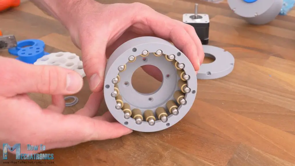
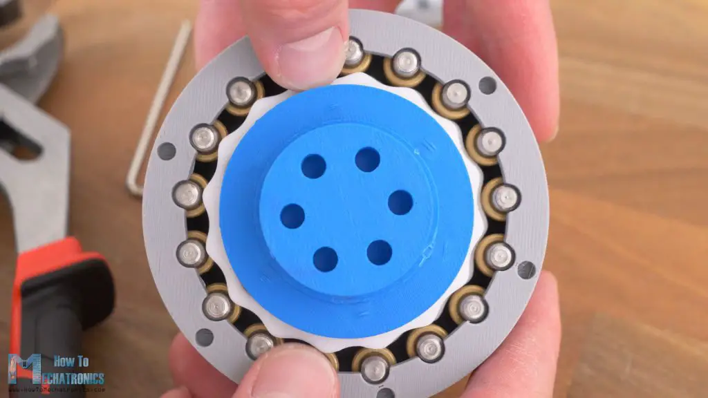
I will start with the cycloidal drive. When designing a cycloidal drive, the main input parameters are the reduction ratio that we want to achieve of course, and the type or the size of the rollers that we will use.
For this build, as rollers I decided to use bushings with 6mm inner and 10mm outer diameter.
These bushings are much smoother than the bushings that I used in my previous builds, with 8mm outer diameter, so I wanted to see if I can get better performance of the cycloidal drive with them. Though, these 10mm bushings come at a price, as the rollers size directly define the size of the cycloidal disks and the whole drive.
Now I will show you how I easily designed the cycloidal drive using Onshape, which is also the sponsor of this video. Onshape is a Professional grade CAD & PDM system, and they’re now offering up to 6 months free of the professional version to engineers and their companies.
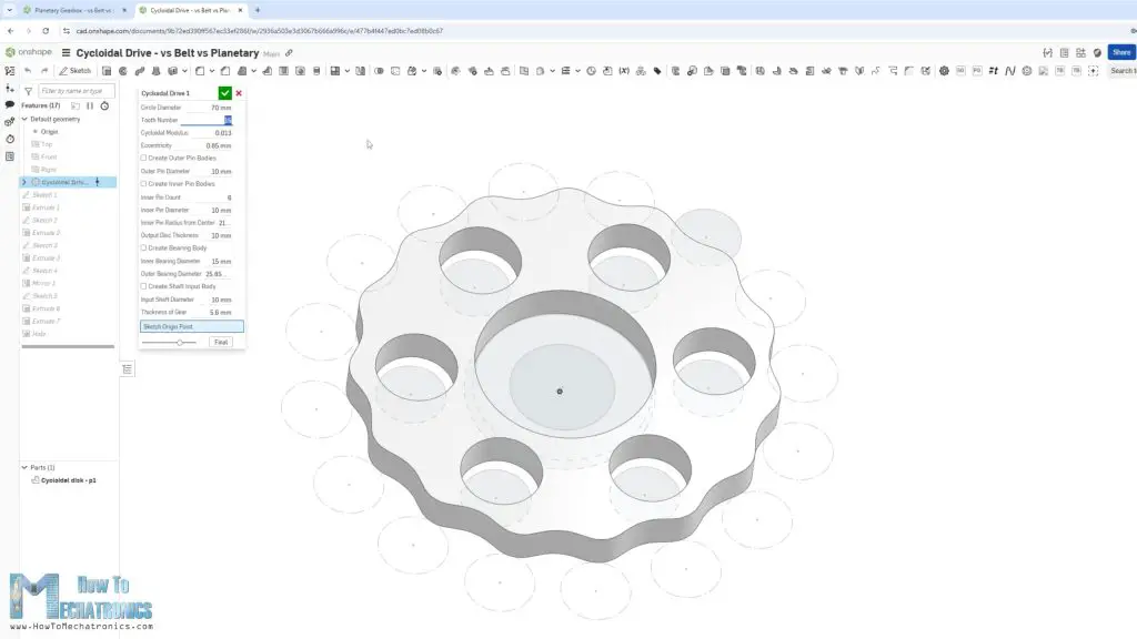
It’s quite easy to generate the cycloidal disk with the help of the custom- build Cycloidal Drive FeatureScripts library in Onshape.
We just have to enter our parameters. The tooth number of the disk, the eccentricity, and the rollers or pins diameters, both the outer pins or ring gear rollers and the inner pins or the output shaft rollers. As we enter these values the 3D model updates as well as the other parameters which we should keep track of and correct them later if needed. The circle diameter is the overall dimension of the disk, and the goal is to be as small as possible according to our fixed input parameters, the number of pins and their dimensions.
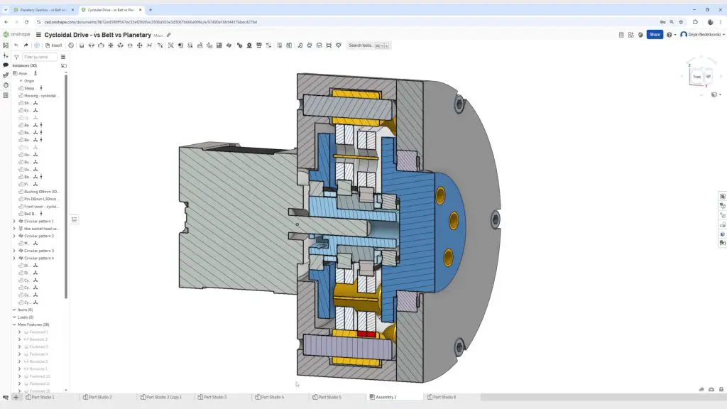
The cycloidal disk is the most important part of the drive, and the rest of the parts are designed around it.
Of course, there are many other input parameters that contribute to the overall design of the drive, such as the motor type, how we would like to drive the input shaft, what kind of bearings we have available to work with, the application of the gearbox itself and so on.
Planetary Gearbox
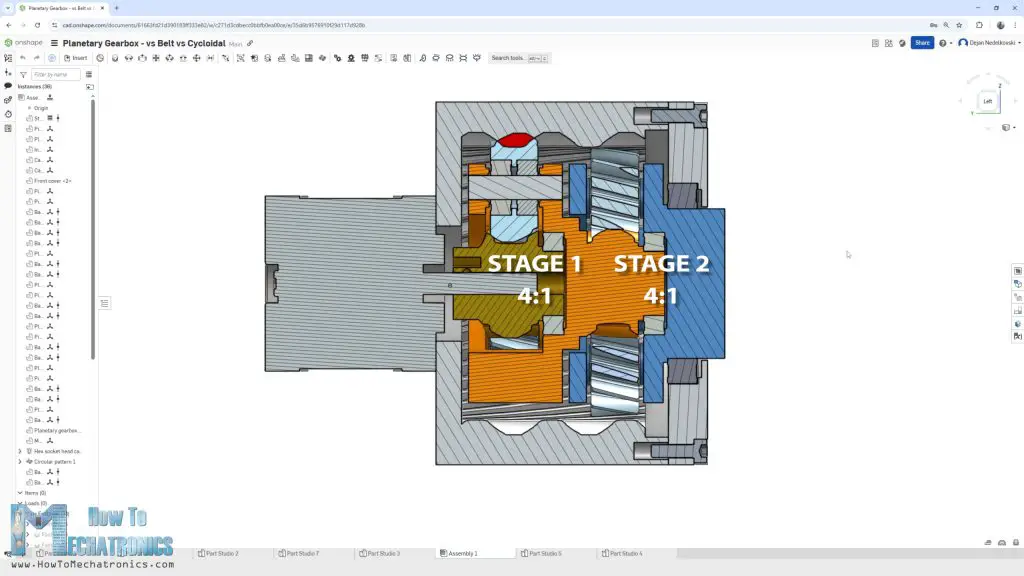
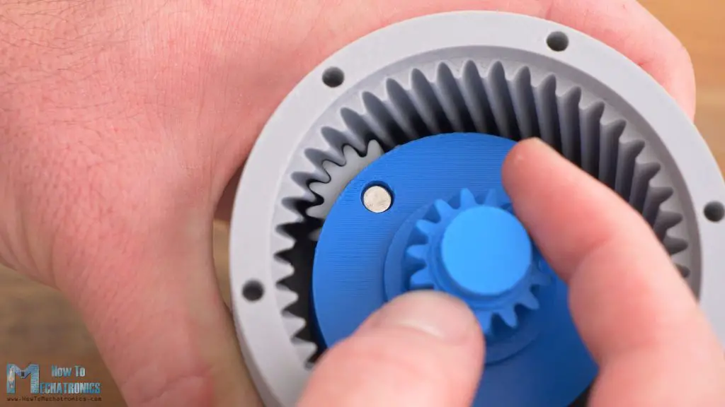
Let’s take a look at the planetary gearbox now. This is actually the same design from my previous video where I talk in details how to design a planetary gearbox. It’s a two-stage planetary gearbox, with 4:1 reduction on each stage, for total of 16:1 ratio.
For better performance, instead of bushings, here I’m using ball bearings for the planet gears. Each planet gear accommodates two ball bearings so we can easily lock the gear in place and accept the axial forces that occur since the gears are helical.
Belt Drive
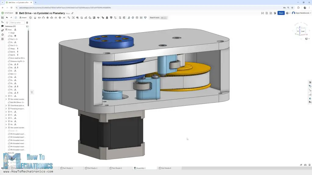
Next, let’s take a look at the belt drive. Here we also want the same reduction ratio of 16:1 and we can easily make that in two stages with 4:1 ratio.
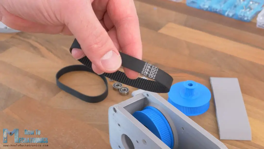
I chose to use a GT2 belt because it is the most popular and available belt and it offers great performance in terms of backlash. Almost all 3D printers use this type of belts. I got two 226mm closed loop GT2 belts with 10mm width.
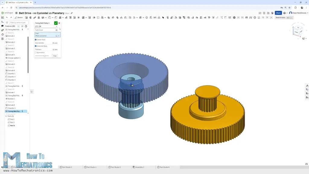
Now for these belts to work, we need suitable GT2 pulleys. Again, using a custom-built FeatureScript library in Onshape, we can easily generate the GT2 pulleys.
Here, we just have to select the type of the GT2 belt, whether it’s 3M or 2M, or that’s 3 or 2mm pitch, and enter the number of teeth the pulley will have.
I set the input pulleys to have 20 teeth, and the output pulleys 80 teeth. The first stage output pulley with 80 teeth is the input pulley with 20 teeth for the second stage and it sits on two ball bearings.
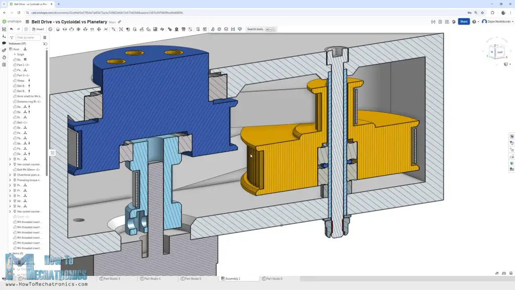
The shaft for it is a 6mm 3D printed shaft with M4 bolt that goes through it for making it stronger. The second stage output pulley is supported with two ball bearings, one at the motor input shaft and the other at the housing.
3D Models
View and explore the 3D Models:
Cycloidal Drive: https://bit.ly/3RsTa6g
Belt Drive: https://bit.ly/3DZGIb7
Planetary Gearbox: https://bit.ly/3XGtTsZ
This section is still under construction. The STL files fill be available soon.
3D Printing
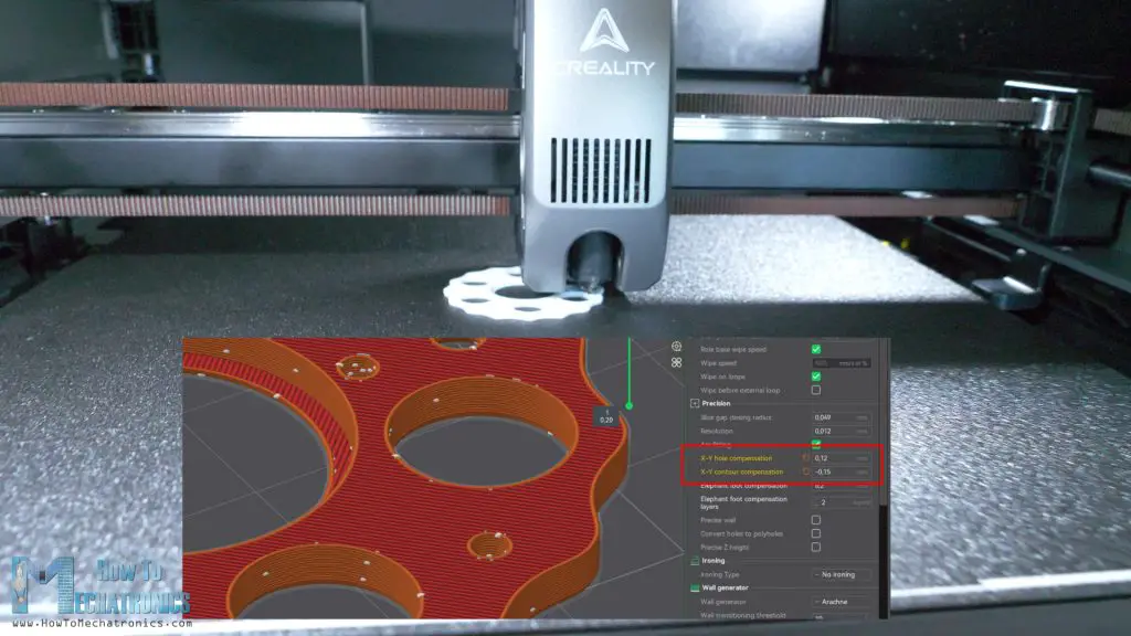
I used the Creality K2 Plus 3D printer for printing all of the parts. When 3D printing, it’s essential to use the Horizonal Expansion feature, or now in the new Creality Print slicer, it’s called X-Y contour compensation and X-Y hole compensation.
If we leave these settings by default, the prints dimensions probably won’t come out exactly the same as in the CAD model and that’s due to the expansion of the filament when 3D printing. The holes usually come out smaller, and the contours bigger.
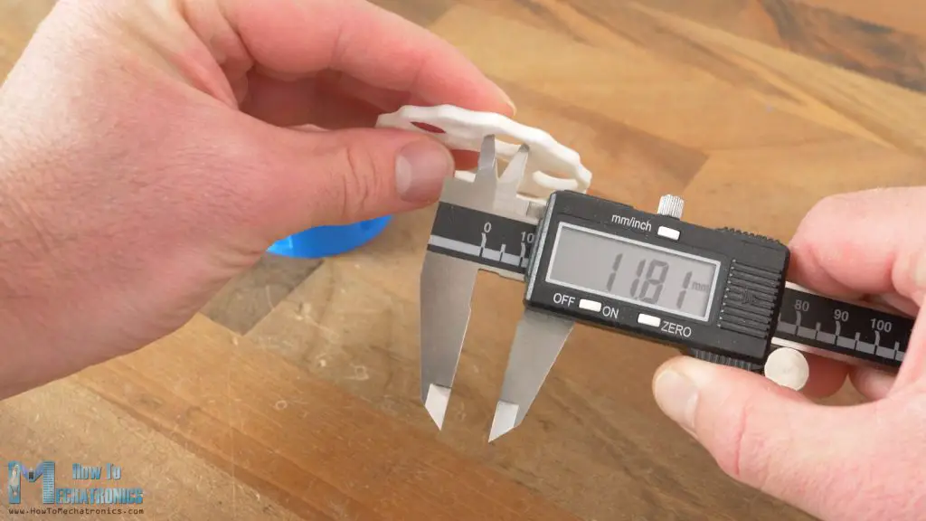
Now what values to use for these two settings is the key question because they directly affect the precision or the performance of the drives that we are making. I actually used different values for each part, depending on the purpose of the part.
For example, when 3D printing the cycloidal disks, I used values of 0.12mm for the X-Y hole compensation, and –0.15mm for contour. In that way I got the holes for where the output rollers go at right dimension, as well as the contour of the disk which needed to be smaller in order to fit in the ring gear rollers.
I made a list of all values that I used for each part. Horizontal expansion or X-Y compensation values list:
| Part | Contour Compensation | Hole Compensation |
|---|---|---|
| Cycloidal Drive | ||
| Cycloidal disk | -0.15mm -0.20mm for looser fit | 0.10mm 0.15mm for looser fit |
| Eccentric bearing | 0.07mm | 0.03 |
| Shaft coupler | 0.07mm | 0mm |
| Planetary Gearbox | ||
| Ring gear / housing | 0mm -0.10mm for looser fit | 0.05mm |
| Planet gears | 0mm -0.05mm for looser fit | 0.05mm |
| Carrier / output | 0.07mm – in order to fit better with the output bearing | 0.05mm |
| Belt Drive | ||
| GT2 pulleys | -0.05mm | 0.05mm |
You can try these values when you 3D printing, but you might need different values depending on your 3D printer. You can only get these values right by doing some test prints with different values. You will later see in the comparisons tests how adjusting these values affect the performances of the drives.
By the way, shout out to Creality for providing me this excellent 3D printer. The Creality K2 Plus is actually one of the best 3D printers I have ever used. Check my detailed review of the Creality K2 Plus. Also, check it out at: Creality USA store ; Creality EU store ; Amazon.
Assembling the Drives
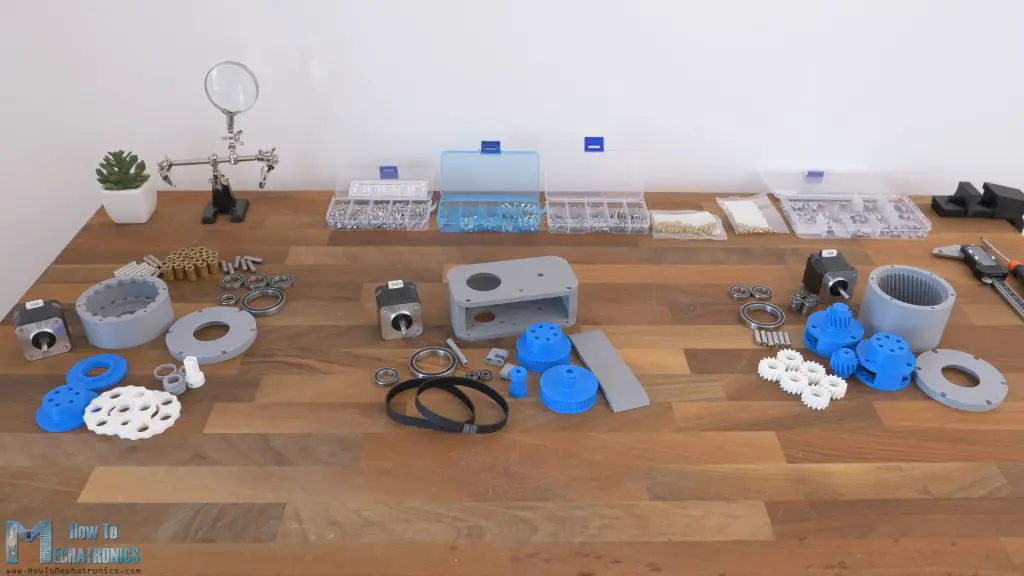
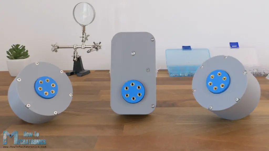
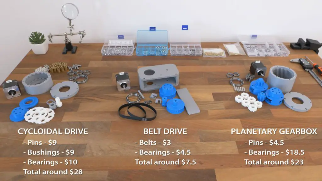
All right, so here are all of the 3D printed parts and other components needed for assembling the three speed reducers.
As we can notice, the belt drive has the fewest number of parts, and on the other hand for the cycloidal drive we need considerably more components like the pins and the bushings. The planetary gearbox is somewhere in the middle for that matter.
BOM
Here’s a complete list of all components need for these drives, the like bushings, the belts, the bearings and bolts and nuts.
| Component | Quantity | Purchase Links |
|---|---|---|
| Cycloidal Drive | ||
| Pins D-6mm, L-30mm | 16 | Amazon | AliExpress |
| Pins D-6mm, L-24mm/25mm | 6 | Amazon | AliExpress |
| Bushings ID6mm OD10mm L16mm or 2xL8mm | 22 | Amazon | AliExpress |
| Ball Bearing 35x47x7 6807 | 1 | Amazon | AliExpress |
| Ball Bearing 17x26x5mm 6803 | 3 | Amazon | AliExpress |
| Ball bearing 12x21x5mm 6801 | 1 | Amazon | AliExpress |
| M3x10mm countersunk M3x10mm | 4 6 | Amazon | AliExpress |
| Planetary Gearbox | ||
| Pins D-6mm, L-22 | 6 | Amazon | AliExpress |
| Ball Bearing 35x47x7 6807 | 1 | Amazon | AliExpress |
| Ball bearing 15x24x5 6802 | 2 | Amazon | AliExpress |
| Ball bearing 6x13x5mm 686 | 12 | Amazon | AliExpress |
| M3x10mm M3x10mm countersunk | 6 4 | Amazon | AliExpress |
| Belt Drive | ||
| GT2 Belt 226mm | 2 | Amazon | AliExpress |
| Ball Bearing 35x47x7 6807 | 1 | Amazon | AliExpress |
| Ball bearing 15x24x5 6802 | 1 | Amazon | AliExpress |
| Ball bearing 6x13x5mm 686 | 2 | Amazon | AliExpress |
| M3x10mm M3x8mm M3x16mm countersunk M3x25mm countersunk | 4 4 2 2 | Amazon | AliExpress |
| Other | ||
| M3 Grub Screws | Amazon | AliExpress | |
| M3 / M4 nuts | Amazon | AliExpress |
Now I will quickly walk you through the assembly process of these drives.
Belt Drive Assembly
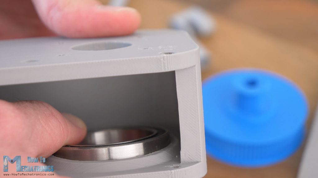
For assembling the belt drive, first we need to insert the final output pulley in place through the ball bearing at the housing.
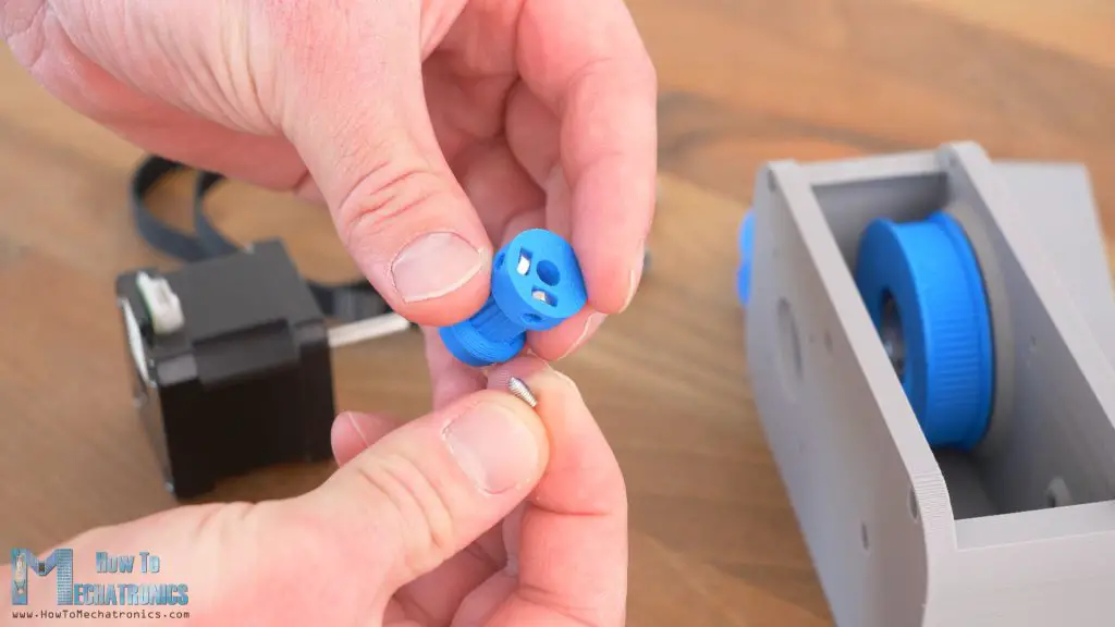
Then we need to install the ball bearing inside the output pulley where the first input pulley will go. This input pulley first needs to be secured to the stepper motor, and for that purpose I made two slots for inserting M3 nuts, and then using M3 grub screws we can firmly secure the pulley in place.
The pulley should stay 2mm above the stepper motor.
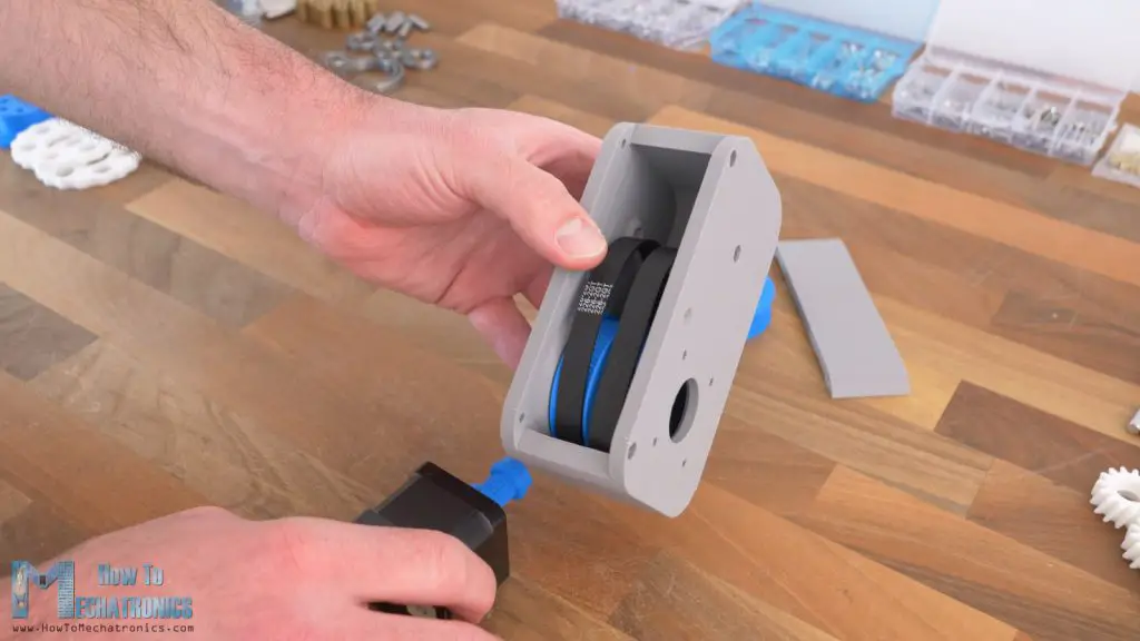
Before inserting the stepper, we need to insert the two belts.
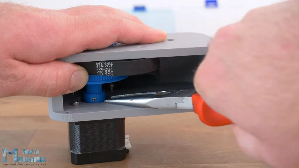
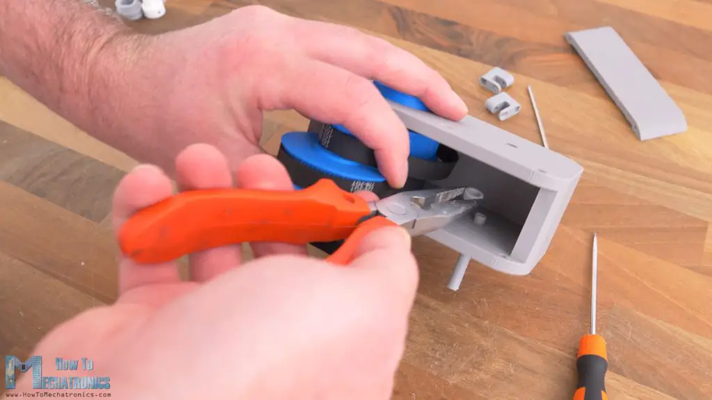
Then we can secure the stepper to the housing using some M3 bolts. As I wanted the drive to be as compact as possible, securing these bolts was only possible with some narrow pliers.
Not convenient at all, but the goal was also the drive to be as sturdy as possible to get the best performance out of it.
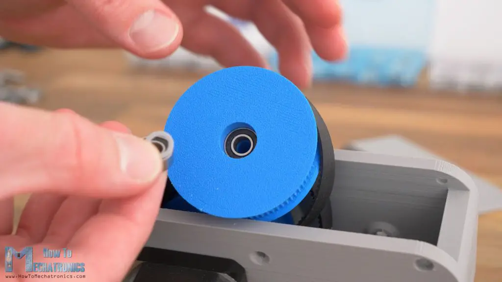
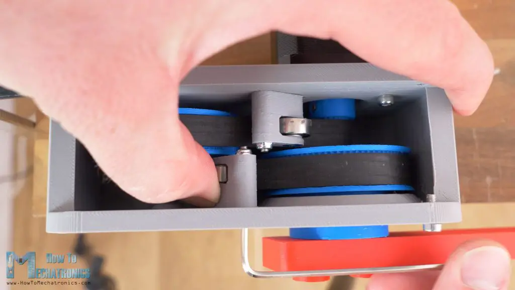
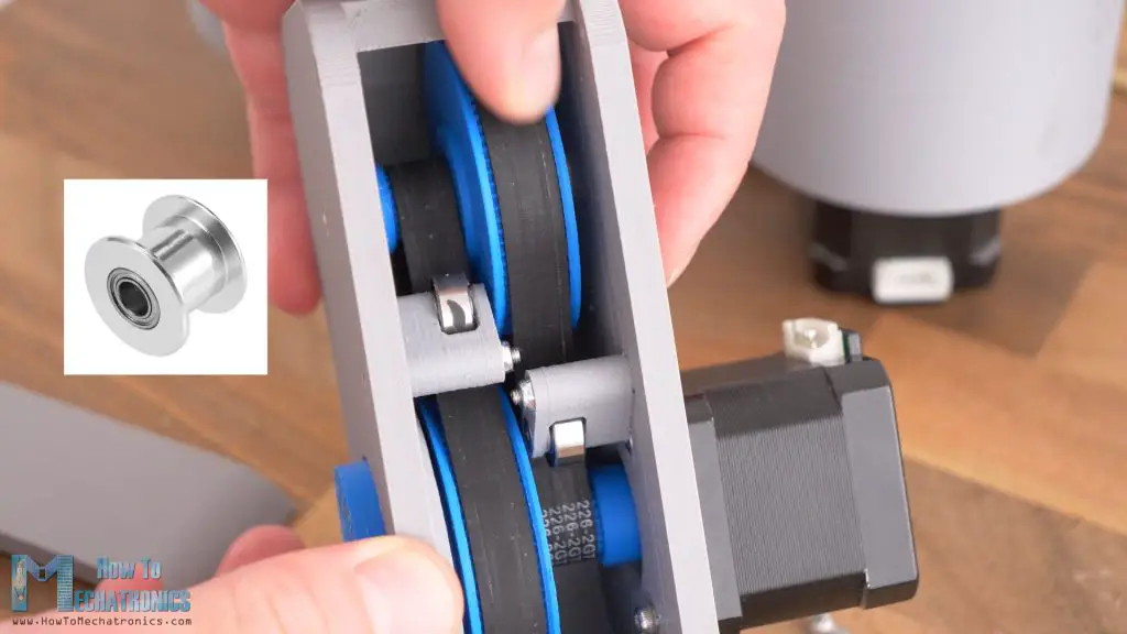
Next, we can insert the intermediate pulley and wrap the two belts around it. This pulley will accommodate two ball bearings with a small distance ring in between them.
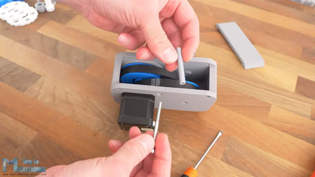
Then we can insert the shaft for the pulley. It’s a 3D printed hollow 6mm shaft that will be reinforced with an M4 bolt.
Here for example, we can use just an M6 bolt instead of this, but in that way, we would have not so tight connection because the M6 bolts outer diameter is about 5.8mm, and with the 3D printed shaft we can make it exactly 6mm or 5.95mm to perfectly through the bearings.
At the bottom side we need to insert a distance ring on which the ball bearing will sit.
Then we can stretch the belts, and insert the shaft all the way through the bearings and into the other side of the housing. Then we can insert the M4 bolt through it and secure everything in place with an M4 nut. And that’s it, the belt drive is done, it works.
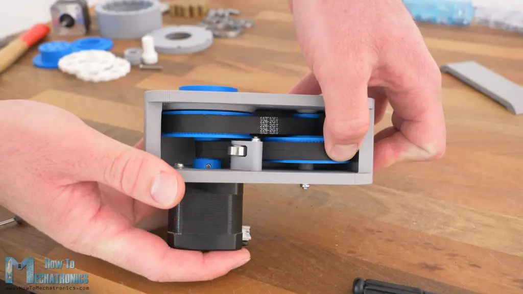
The belts are fairly tight but for better control and performance we should add tensioners to them. I made the belt tensioners with the help of a ball bearing with 13mm outer diameter, that is attached on a small bracket with some M3 bolts and nuts.
We can push this bracket against the belt to tension it and then tight the bolt. It’s a rather simple mechanism that works just right.
Lastly, we can secure the cover of the drive with some M3 bolts and nuts in it, and add threaded inserts to the output shaft for attaching stuff to it.
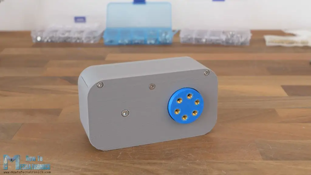
That’s it, the belt drive is done and at first sight, when trying to move the output shaft by hand it feels like there is no backlash at all.
Cycloidal Drive
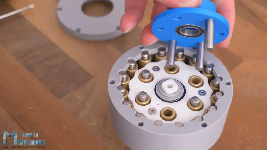
Now let’s take a look at the cycloidal drive build. As I mentioned, I already have detailed videos how to build a cycloidal drive and a planetary gearbox, so here I will just say few words about them.
When assembling the cycloidal drive, I came to a problem that I couldn’t insert the second disk in place, although I was following all the rules, placed it 180 degrees out of phase, and double checked all dimensions.
Then I realized that the problem was the reduction ratio. A cycloidal drive must have an odd number for the ratio in order to work properly. In my previous videos I have already made three different designs of cycloidal drives, but their reduction ratio was an odd number by chance, so I have missed the fact that in order to make a cycloidal drive that will work properly with two cycloidal disks, you need to have an odd number of teeth or lobes on the disks.
You can check the previous designs articles below.
- What is Cycloidal Driver? Designing, 3D Printing and Testing
- CNC Machined vs 3D Printed Cycloidal Drive – Designing & Testing
- Harmonic vs Cycloidal Drive – Torque, Backlash and Wear Test
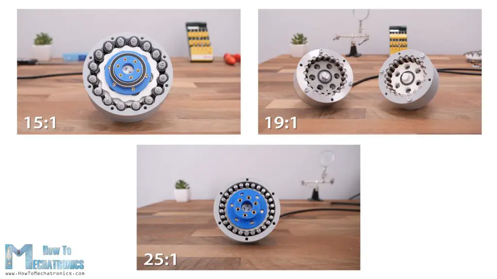
Having odd number of reduction ratio, meant that I had to changed the number of teeth to 15, and the number of ring gear rollers to 16 and re-printed the housing and disks.
Now I was able to install the two cycloidal disks properly and finish the whole assembly.
Backlash Test
All right, so here I have the three drives ready, and now we can take a look at the comparison tests.
I will start with testing the accuracy or the backlash.
Planetary Gearbox
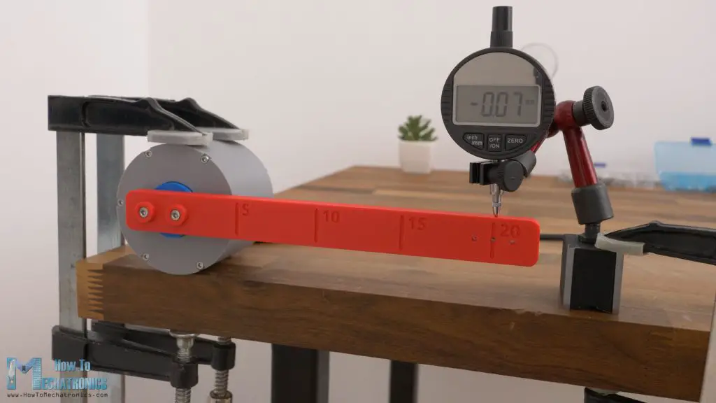
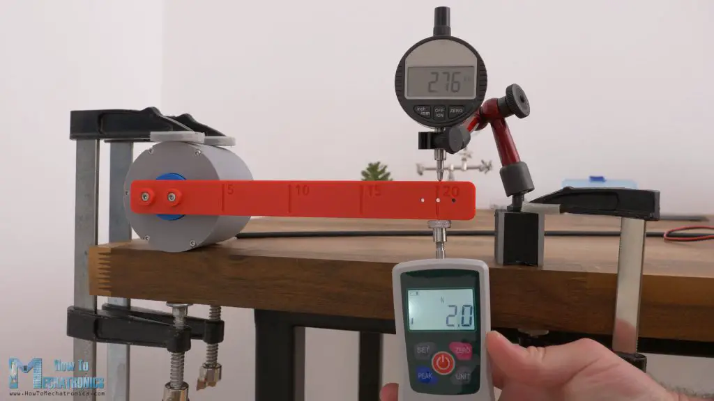
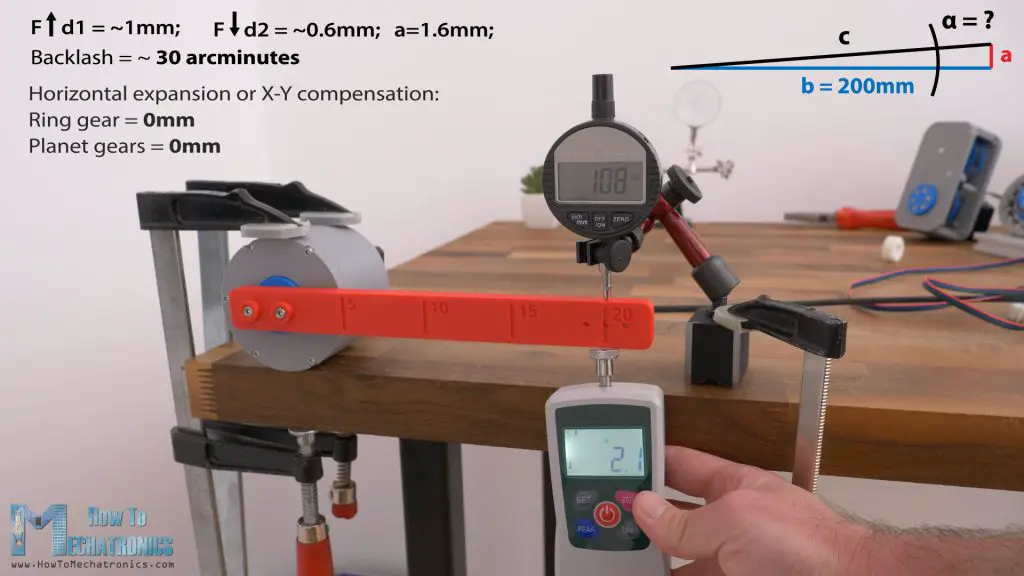
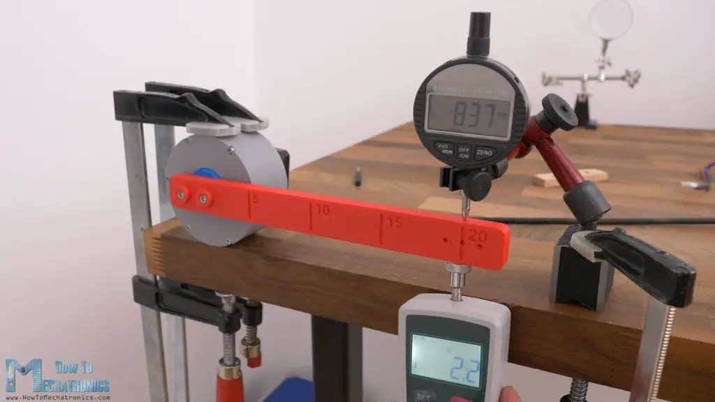
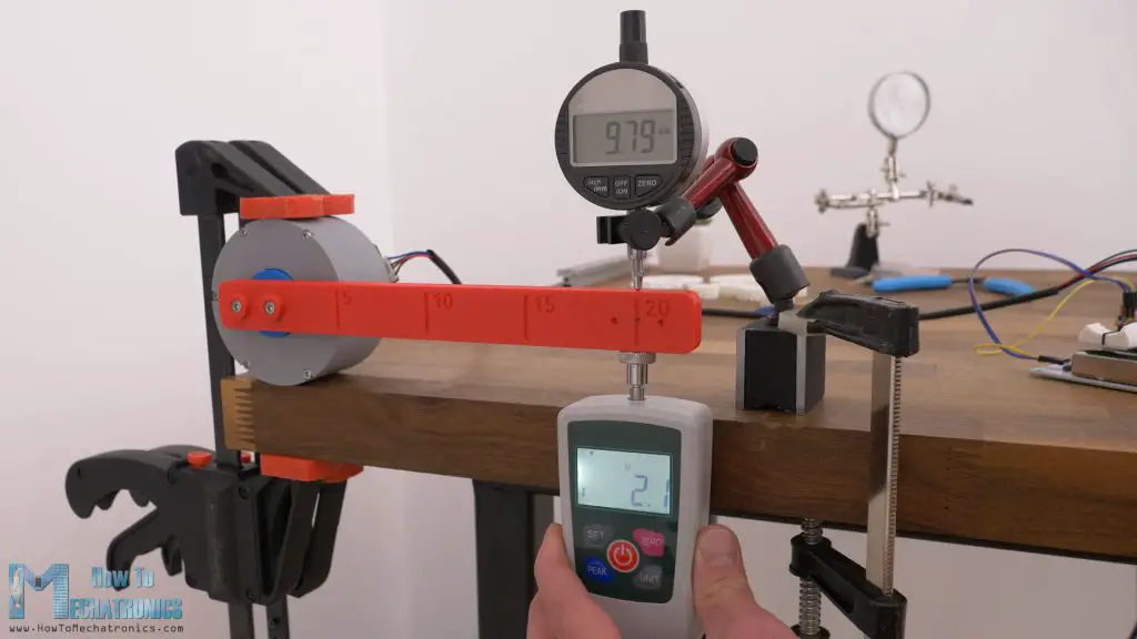
Here’s the planetary gearbox first. Here I’m testing its repeatability, and it shows good results. The bar gets back in place within 1/100 of a mm at a distance of 20cm.
But of course, when applied a force to it, the backlash gets noticeable. The bar plays couple of mm up and down at that distance. When moving it by hand, it feels like there is a free play on the output without any resistance.
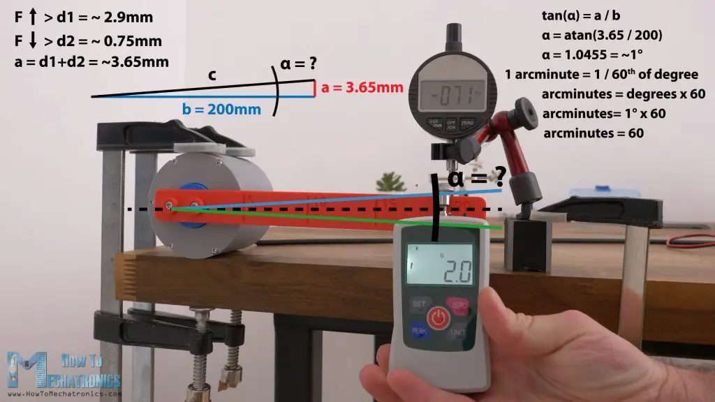
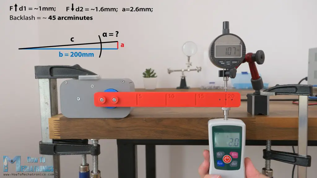
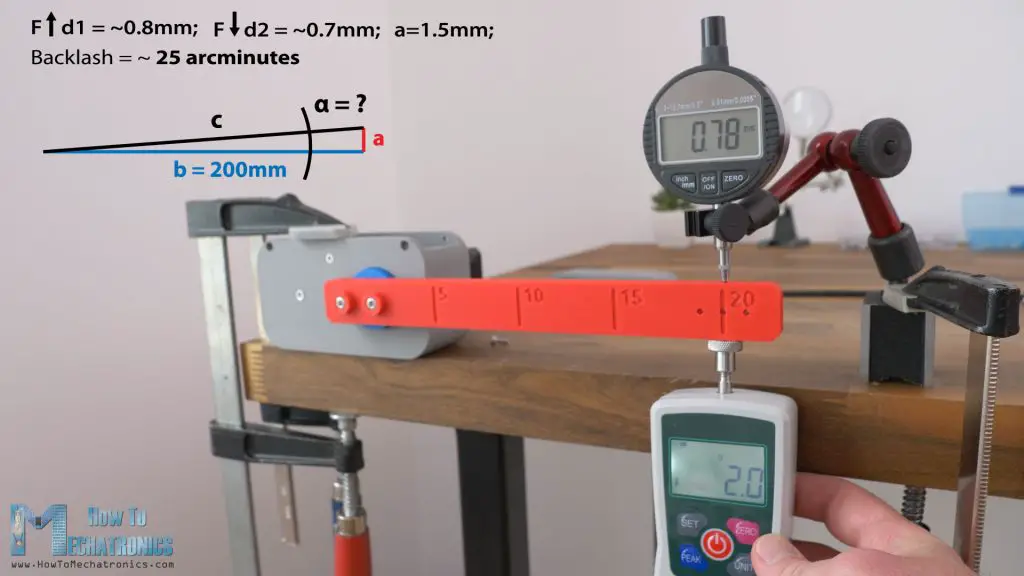
To express the backlash in its typical unit, arcminutes, we need to do the following. We should measure the displacement in both directions, while applying a load of around 1-2% of the nominal torque capability of the gearbox.
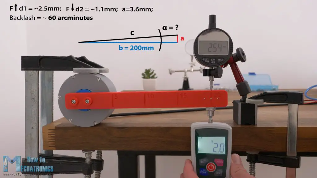
When testing the torque of the gearbox, I got a maximum reading of around 32N at a distance of 10cm, so I guess for testing the backlash we should apply a load of around 0.5N, but let’s make it 2N at a distance of 20cm. With this load I got a displacement of around 2.9mm in one direction and 0.75mm in the other direction.
To express these measurements in backlash unit, arcminutes, first we can calculate the angle of displacement, alpha.
We do that with the help of some simple trigonometry, and the angle comes out to be around 1 degree. One arcminute is 1/60th of a degree. So, the backlash of this 3D printed planetary gearbox is around 60 arcminutes.
Please let me know in the comments if you know whether that’s the right way to take the measurements and calculate the backlash. Even if it’s not 100% correct, we will use the same method to express the backlash for each drive so that at the end we will have comparable results.
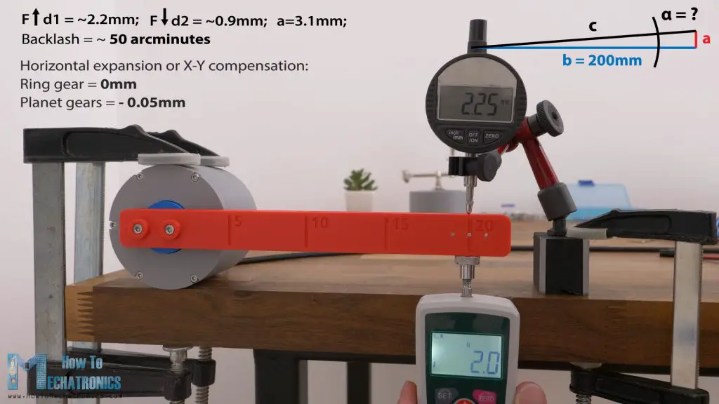
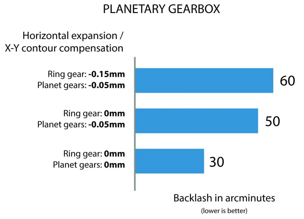
Now as I mentioned earlier, depending on how tight or lose the meshing of the teeth is, the gearbox should provide different result. And here’s a confirmation for that. In the first test, the gearbox ring gear was printed with horizontal expansion of –0.15mm and the planetary gears with –0.05mm.
Now I replaced the ring gear with horizontal expansion of 0mm, which made a tighter fit. Now gearbox showed a backlash of around 50 arcminutes.
That’s like 15% better results, and it could be even felt by hand that the gearbox now has less play.
To further improve the backlash, I printed the planetary gears also with 0mm horizontal expansion, and again I got better results, around 30 arcminutes.
So, from the initially from 60 arcminutes we improved the backlash of the gearbox to 30 arcminutes.
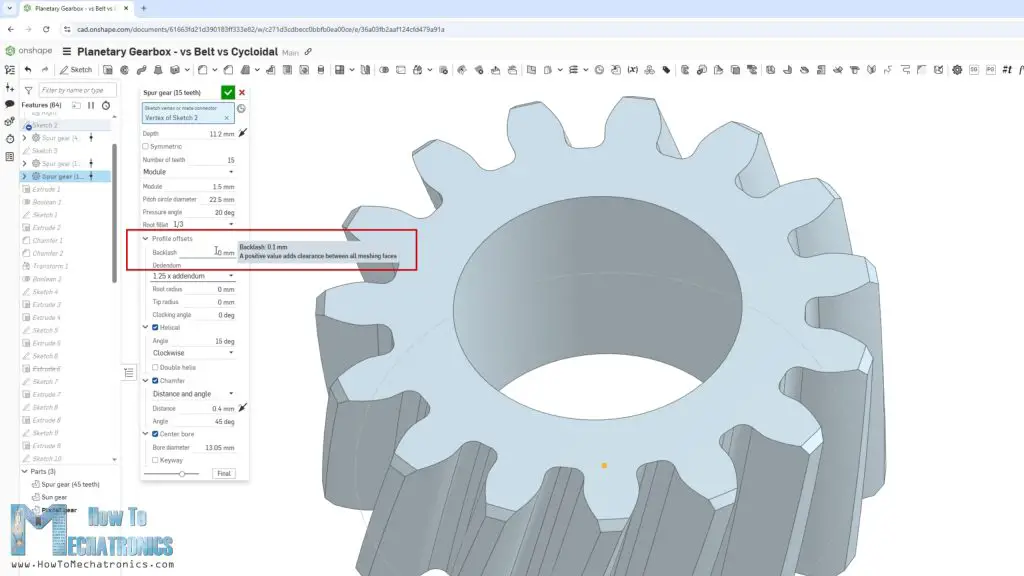
Please note though that in the design process itself, when generating the gears with the custom FeatureScript in Onshape, I added a backlash or offset of 0.1mm to the gears.
So, that’s why I can print them with all with 0mm horizontal expansion and still be able to assemble them properly and get good results. That means we can even further increase the backlash remove that 0.1mm offset when generating the gears, but I believe that if we do that, we won’t be able to assemble the gears at all, or maybe we will be able to put them together, but they will lose efficiency or even jam completely. We will see that behavior in a bit in the efficiency or torque test.
Cycloidal Drive
Nevertheless, now let’s take a look at the cycloidal disk backlash performance. In terms of repeatability, it showed worse results. The bar was getting back at various points within 1/10 of a mm.
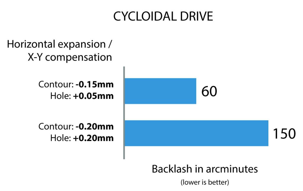
As for the backlash, I calculated a value of around 60 arcminutes. That’s the same like in the worst case with the planetary gearbox. Though, here when moving it by hand, it didn’t feel like there is a free play, but there was some resistance right away.
For this test, the cycloidal disks were printed with –0.15mm horizontal expansion, and when assembling they were actually quite tight. So, I tried printing them with –0.2mm horizontal expansion and +0.2mm hole expansion, because the precision of the 6 output holes in the cycloidal disk also contribute to the performance of the drive.
So, with looser fit of the disks, the results were much way worse, around 150 arcminutes and there was a free play of the shaft when moving it by hand.
Belt Drive
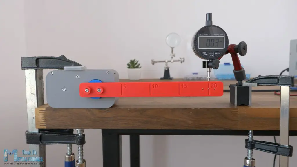
Ok, next let’s take a look how the belt drive performed. The repeatability seems to be quite good, within 1/100 of a mm at a distance of 20cm. But we can also notice that there is like an overshoot. The bar goes up to 0.04mm and gets back to 0.03.
When testing the backlash, I calculated a value of around 45 arcminutes.
That’s a good result compared to the other two drives, but I here with the belt drive I also have the possibility to control the tension of the belt and with that maybe improve the backlash.
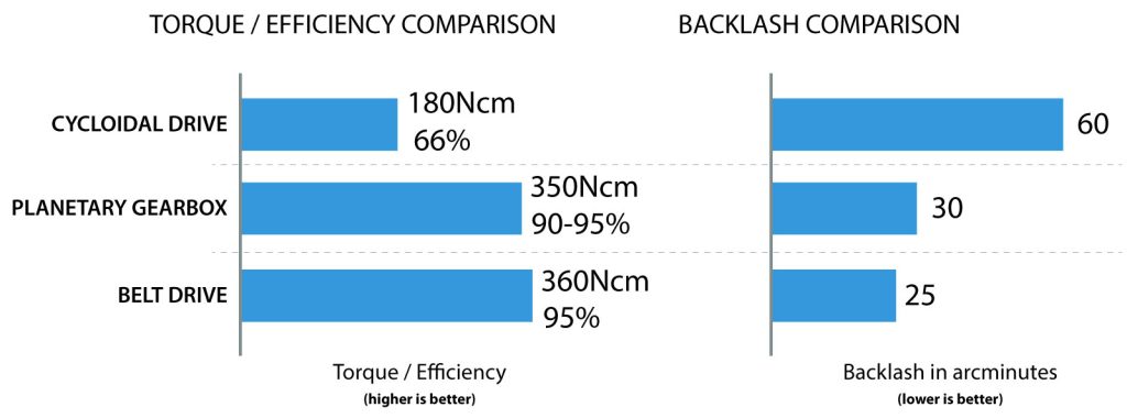
I did tension the belt a bit more, and now backlash was reduced to around 25 arcminutes.
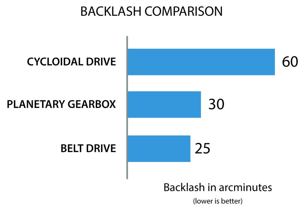
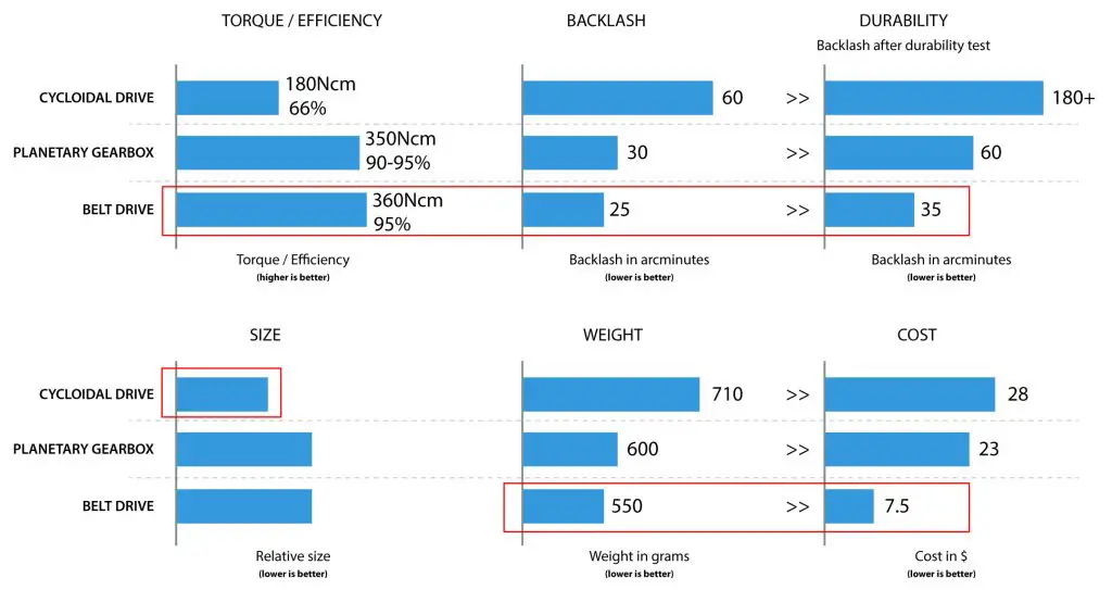
So, the belt drive gave to be the best results out of the three drives in terms of backlash.
Torque / Efficiency Test
Cycloidal Drive
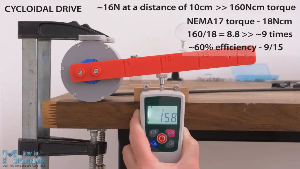
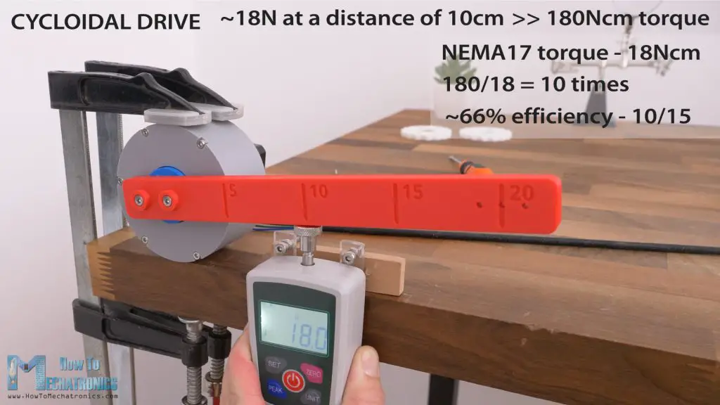
Ok, now let’s compare their efficiency or torque output. I will start with the cycloidal drive. At a distance of 10cm, I got a reading of around 16N, or that’s a torque of around 160Ncm.
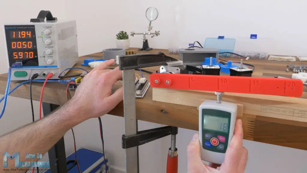
Compared to the torque the stepper motor showed without the drive, around 18Ncm, that’s a torque increase of around 9 times.
That’s a low efficiency of the drive of just around 60%. The reduction ratio of this drive is 15:1, and in ideal conditions we should get 15 times torque increase, but we got around 60% of that. That’s so because I guess there is a lot of friction going on in the drive, or high resistance as the cycloidal disks fit was quite tight.
If we compare that with the cycloidal disks that had looser fit, I got a reading of around 18N, or 180Ncm.
That’s like 10% better efficiency, but still not great, only around 66% efficiency. An on top of that, the backlash with the looser cycloidal disks was enormous, totally not usable for any precision work.
Planetary Gearbox
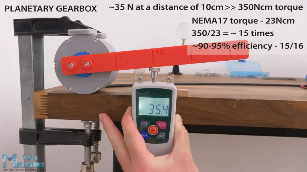
Let’s take a look at the planetary gearbox efficiency now. At a distance of 10cm, I got a reading of around 36N, or that’s a torque of around 350Ncm.
I was kind of surprised by these results, because compared to the torque the stepper motor showed without the drive, in this case around 23Ncm, that’s a torque increase of around 15 times. This gearbox has a reduction ratio of 16:1, so that’s around 90 to 95% efficiency. Though, this test was made with the gears with looser fit, where there was a small play of the shaft when moving it by hand.
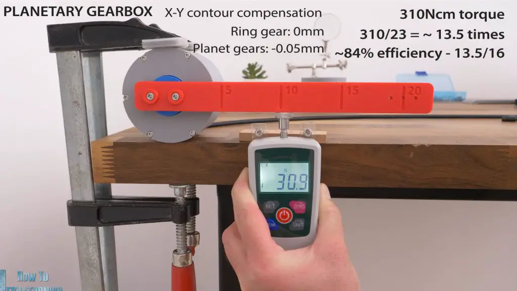
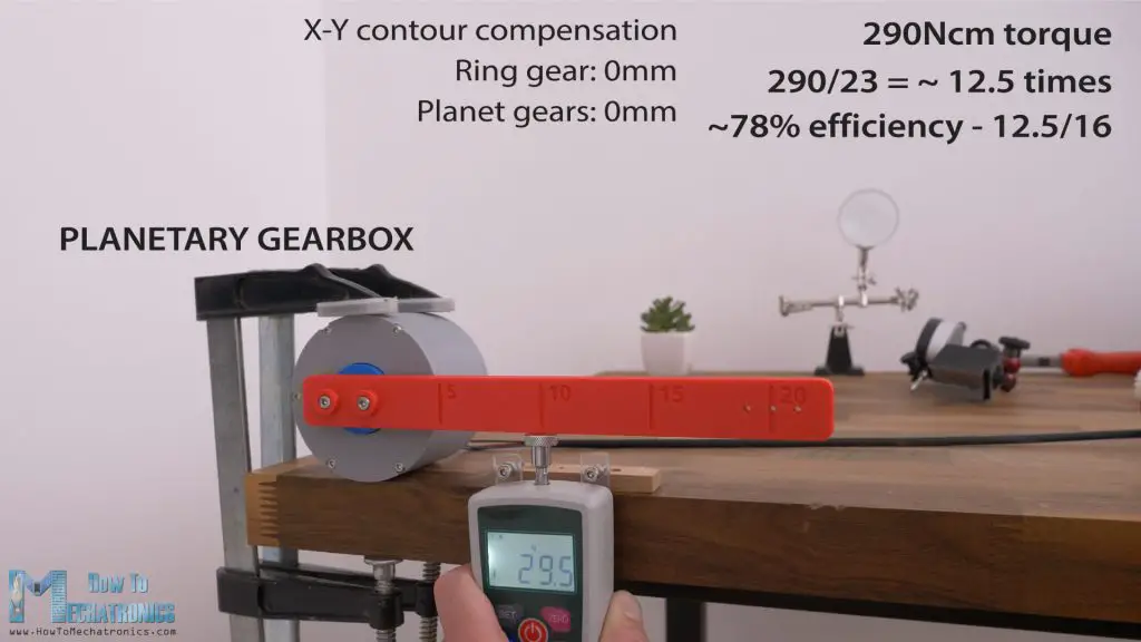
But here are the two other cases that I tested, with tighter fits of the gears meshing.
I got around 310Ncm torque output with ring gear 3D printed with 0mm horizontal expansion, or that’s around 84% efficiency.
And with even tighter fit of the gears, with all planetary gears 3D printed with 0mm horizontal expansion, around 290Ncm torque output, or that’s 78% efficiency. Still, a very good result for a 3D printed gearbox.
Belt Drive
Lastly, let’s take a look at the belt drive efficiency.
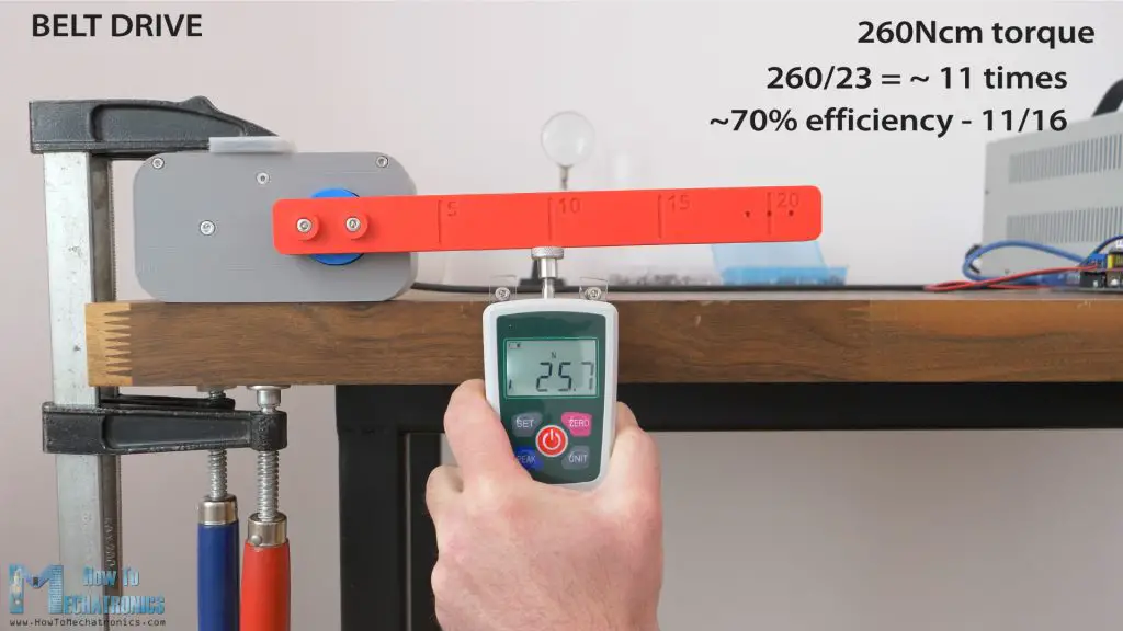
In this first test with the belts being a bit looser, I got a reading of around 260Ncm, which is efficiency of around 70%, as this stepper had a torque of around 23Ncm without the drive. However, in this case the problem was that belt was skipping at the second stage smaller input pulley, instead of the stepper itself.
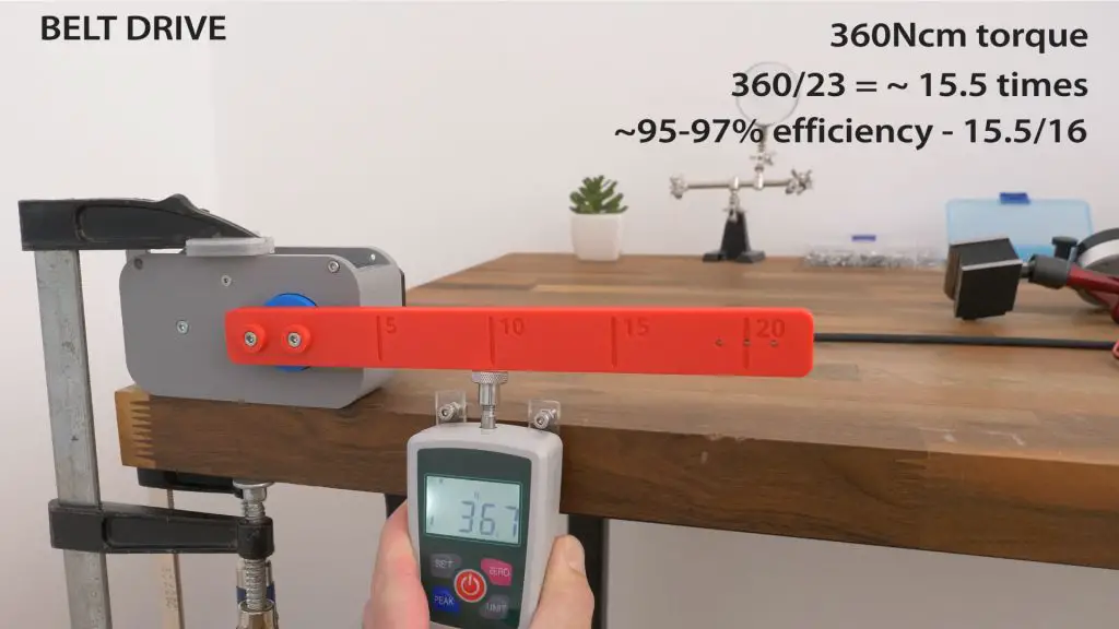
With the belt tensioned better, the output torque was around 360Ncm, that’s efficiency of around to 95 to 97%.
That’s really impressive. The belt drive came out to be the most efficient drive, as well as the best performer in terms of backlash.
But before we make a conclusion which 3D printed drive is the best, let’s take a look at few more comparisons.
Durability Test
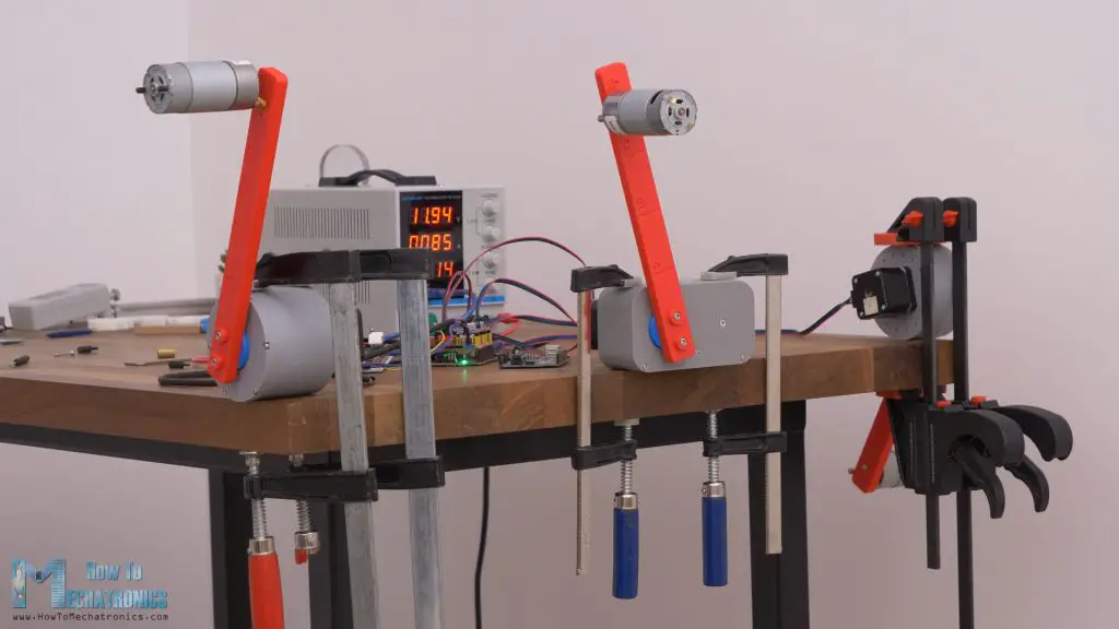
I tried to do a durability test, by running the drives for a longer period of time, with some weight on them.
I used some DC motors as weight, and made the drives rotate with a sudden change in the direction of rotation in order to add more stress to them.
After around 2 hours, the cycloidal drive failed. It couldn’t move the load anymore. The belt drive and the planetary gearbox continued for 8 more hours with the same movements, and they were just fine. After this durability test, I tested again their backlash.
The cycloidal drive totally lost its precision. There was like 10mm free play at a distance of 20cm.
The planetary gearbox also introduced free play on the output shaft, which previously didn’t exist. I was using the gears with the tightest fit for this durability test. In backlash unit, it went from around 30 arcminutes before the test, to 60 arcminutes after the test.
And the belt drive, after the durability test it showed a backlash of around 35 arcminutes, and before the test there was around 25 arcminutes of backlash.
I opened the drives to see what has been going on inside and what causes the precision reduction.
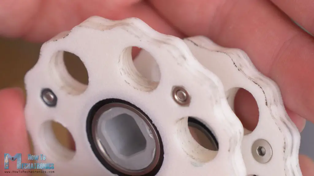
In the cycloidal drive, there were significant marks of wear on the cycloidal disks. Both on the cycloidal disk profile and the output holes of the disks. So, as the PLA disks deformed, they have reduced the precision of the drive significantly.
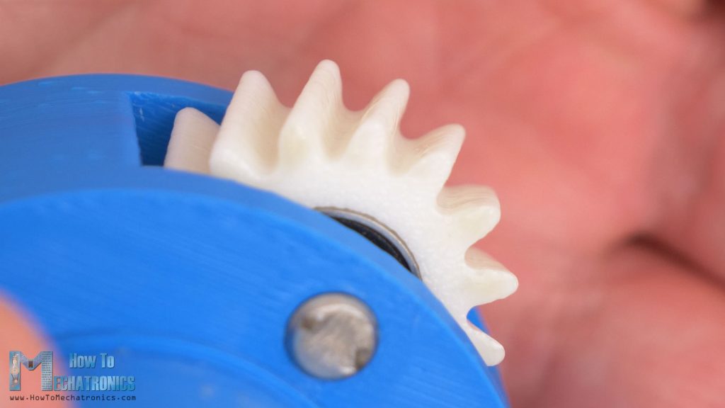
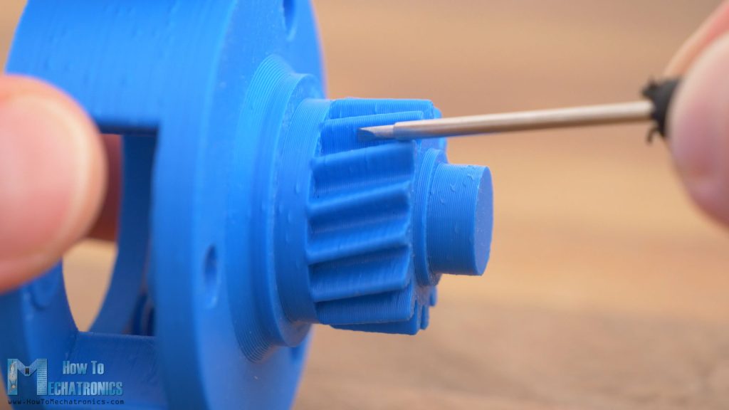
On the planetary gearbox, I couldn’t notice much wear or deformations.
There is probably some very small deformations or wear, maybe the wear of the seams bubbles that appear when 3D printing them. So, once that seams wear out, the backlash increases.
Maybe if we print the gears with even smaller tolerances, or make them fit tighter at the beginning, even at a cost of losing some efficiency, but after the initial wear out, they will get the right efficiency and precisian.
As for the belt drive, we can notice that there is wear on the back side of the belt, where the tensioner bearing pushes the belt.
This problem can be easily solved by using a proper 10mm idler wheel. Also, we can always add more tension to the belts even after some use to improve precision. With the other two drives, there is nothing we can do to improve the precision. We cannot add material to them, or we cannot tension anything.
So, considering all of this, the belt drive came out as the best performer.
And not just that, it also beat the other two drives in terms of weight, cost and how easy it is to be made.
Other Comparisons
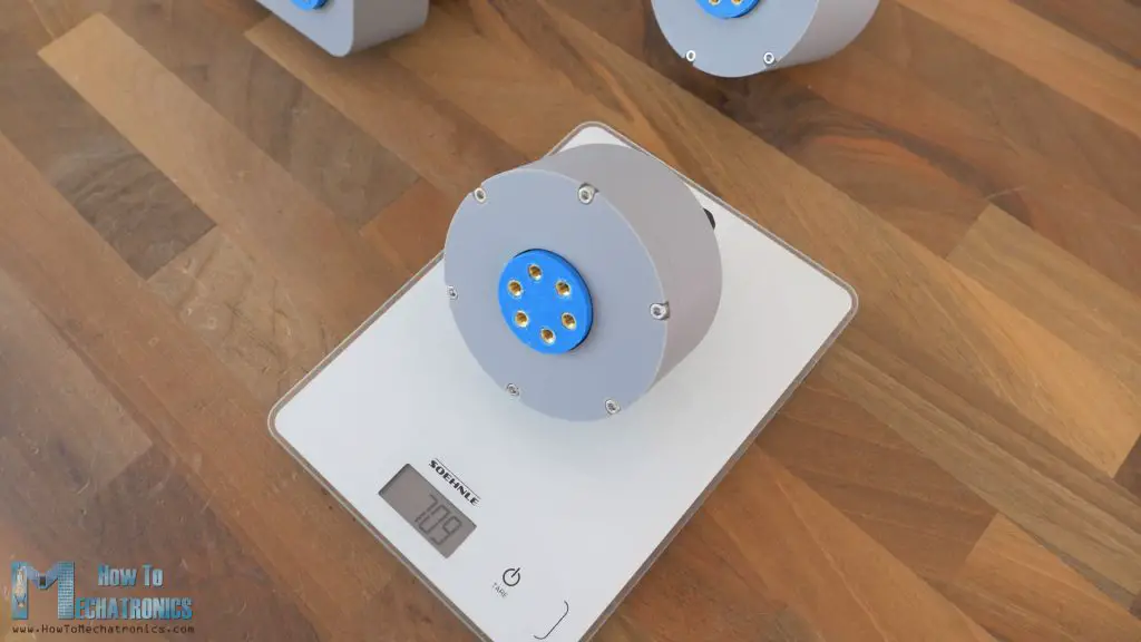
The total weight of the belt drive including the stepper motor was around 550g, the planetary gearbox around 600g and the cycloidal drive around 710g. Of course, the weight is very important if we use these drives as robot joints.
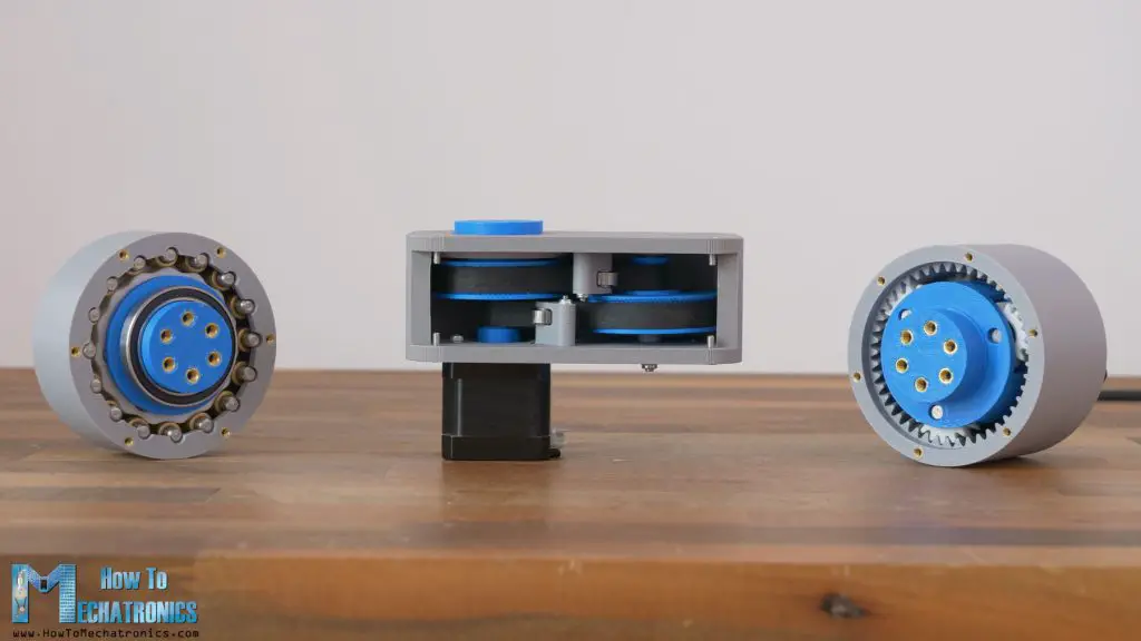
In terms of size, the cycloidal drive is definitely the most compact drive, while the planetary gearbox and the belt drive are somewhere similar but with a bit different configuration.
On the other hand, the cycloidal drive is the most complex or difficult to assemble, followed by the planetary gearbox and the belt drive as the easiest to assemble. That’s so because the belt drive actually has the fewest number of components other than 3D printed parts.
This also directly affects the cost of building the drive. This cycloidal drive that I build for this video, has the most components other than the 3D printer parts, pins, bushings and bearings, costs around $28 to build (not include the 3D printed parts). Then we have the planetary gearbox that costs around $23, and lastly the belt drives that costs only 1/4 or 1/3 of that, or around $7.5.
Conclusion
So, what’s my final verdict. What’s better, a 3D printed cycloidal drive, planetary gearbox or a belt drive?
Well, I would definitely avoid the cycloidal drive, as the only category that was better than the other drives was in its size or compactness.
On the other hand, planetary gearbox and the belt drive showed very similar performance, but if I must pick a winner from all the tests that I made, that must be the belt drive. It performed the best in every category, precision, efficiency and durability, as well as it was easiest and cheapest to build.
However, I won’t leave this test here, but actually I will make further test comparisons between the planetary gearbox and the belt drive in real scenarios, or I will build two robot arms, one employing planetary gearboxes and the other employing belt drives, and then we will see how they will perform in real situation.
