In this tutorial we will learn how to control a brushless motor using Arduino and ESC. In case you want more details how BLDC motors work, you can check the other article or watch the following video which contains explanation of the working principle of a brushless motor and how to control one using Arduino and ESC.
Overview
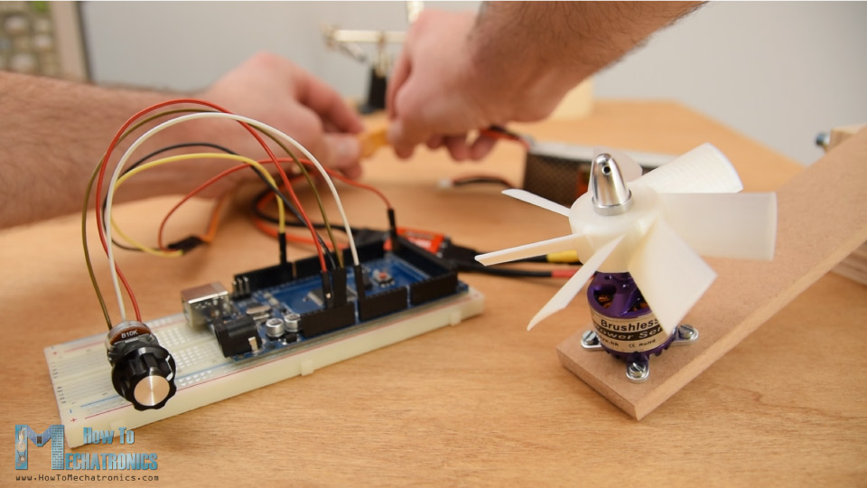
For this example, I have an outrunner BLDC motor with the following specifications: it has a KV rating of 1000, it can be powered using 2S, 3S or 4S LiPo battery and it requires 30A ESC. The KV rating on a brushless motor defines the RPM of the motor per volt with no load.
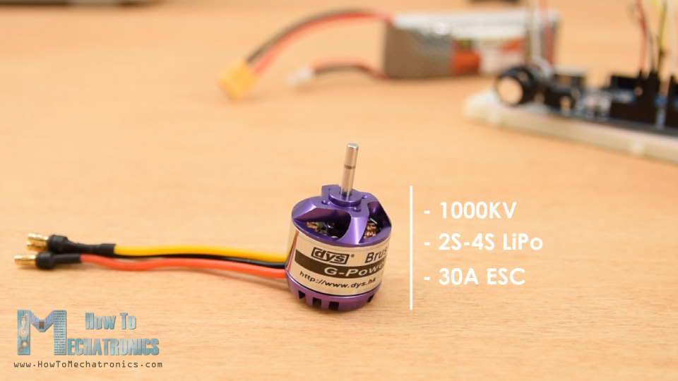
In this case, the 1000KV means that, for example, if we supply the motor with 2S LiPo battery which has a voltage of 7.4 volts, the motor can achieve maximum RPM of 7.4 times 1000, or that’s 7400 RPM.
Brushless motors are power hungry and the most common method for powering them is using LiPo batteries. The “S” number of a LiPo battery indicates how many cells the battery has, and each cell has a voltage of 3.7V.
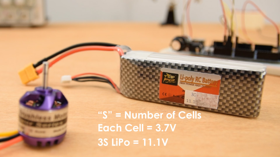
For this example, I will use 3S LiPo battery which has 3 cells and that’s 11.1V. So, I can expect my motor to reach maximum RPM of 11100.
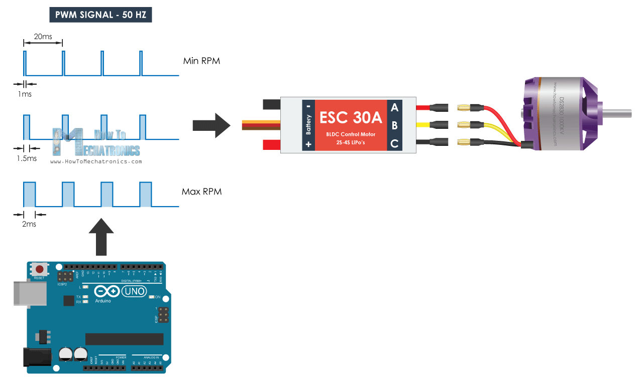
Lastly, here’s a 30A ESC that I will use for this example and match with the motor requirements. On one side the ESC has three wires that control the three phases of the motor and on the other side it has two wires, VCC and GND, for powering.
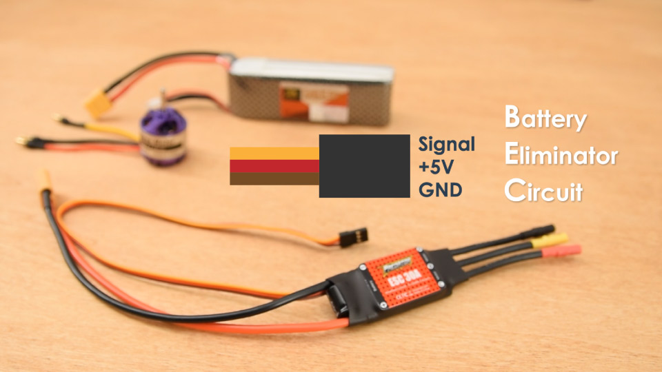
There is also another set of three wires coming out of the ESC and that’s the signal line, +5V and ground. This feature of the ESC is called Battery Eliminator Circuit and as the name suggests it eliminates the need of separate battery for a microcontroller. With this, the ESC provides regulated 5V which can be used to power our Arduino.
We can notice here that this connection is actually the same as the one we see on Servo motors.
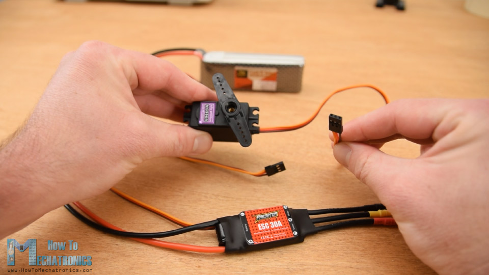
So, controlling a brushless motor using ESC and Arduino is as simple as controlling servo using Arduino. ESCs use the same type of control signal as servo and that’s the standard 50Hz PWM signal.
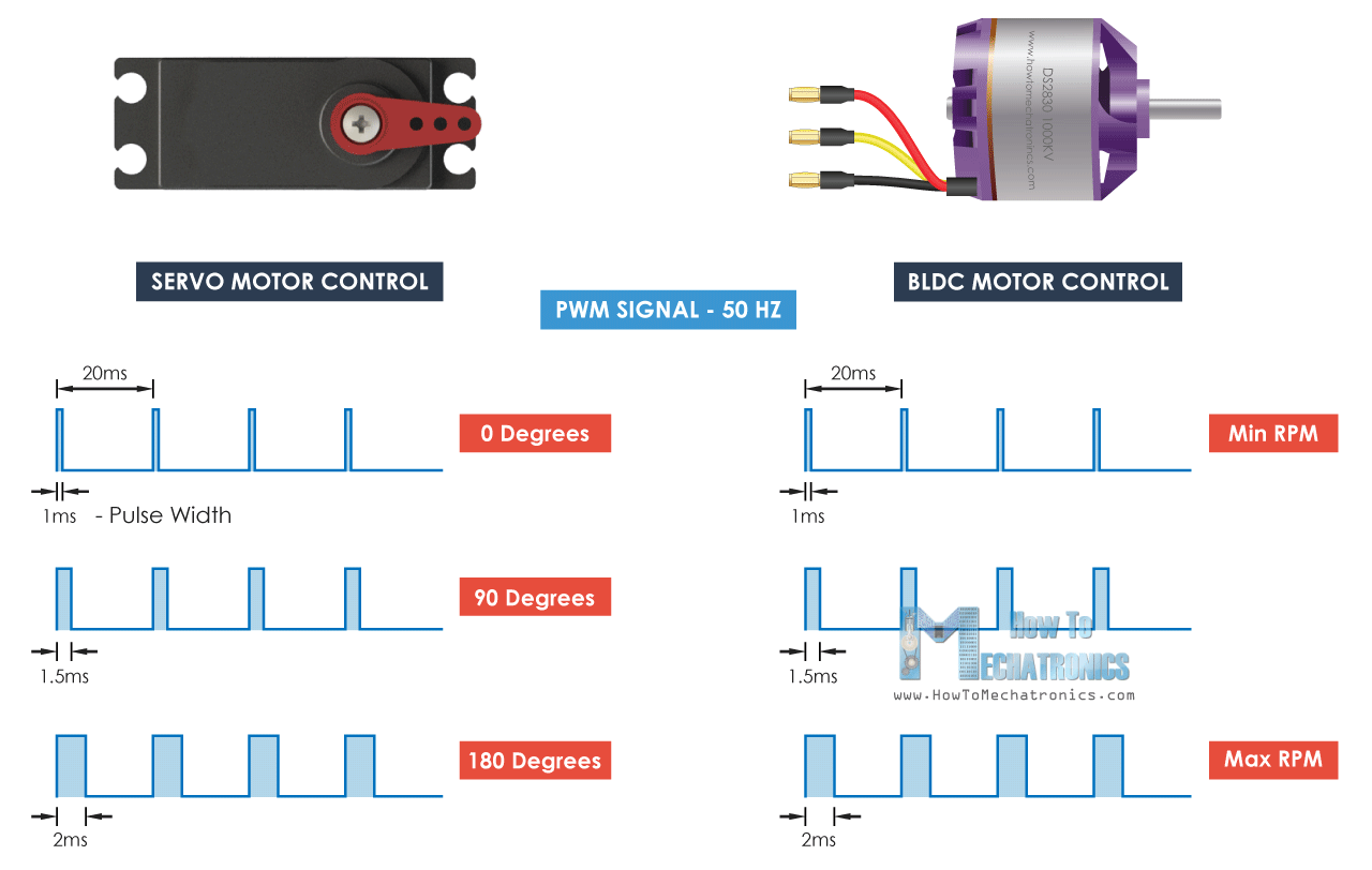
This very convenient, because for example, when building an RC plane, we usually need both servos and brushless motors and, in this way, we can control them easily with the same type of controller.
So, using the Arduino we just have to generate the 50Hz PWM signal and depending on pulses width or the high state duration which should vary from 1 millisecond to 2 milliseconds, the ESC will drive the motor from minimum to maximum RPM.
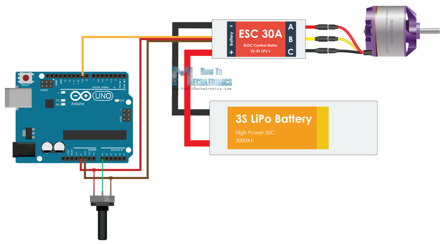
Arduino Brushless Motor Control – Circuit Diagram
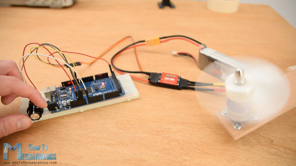
Here’s the circuit diagram for this example. In addition to the ESC we will just use a simple potentiometer for controlling the motor speed.
You can get the components needed for this Arduino Tutorial from the links below:
- Brushless Motor ……………………… Amazon / Banggood / AliExpress
- ESC 30A ……………………………………. Amazon / Banggood / AliExpress
- Li-Po battery ……………….…..…… Amazon / Banggood / AliExpress
- Arduino Board ………………………… Amazon / Banggood / AliExpress
- Potentiometer …………………………. Amazon / Banggood / AliExpress
- Breadboard and Jump Wires … Amazon / Banggood / AliExpress
Disclosure: These are affiliate links. As an Amazon Associate I earn from qualifying purchases.
Arduino Code for BLDC Motor Control
The Arduino code is really simple with just few lines of code.
/*
        Arduino Brushless Motor Control
     by Dejan, https://howtomechatronics.com
*/

#include <Servo.h>

Servo ESC;     // create servo object to control the ESC

int potValue;  // value from the analog pin

void setup() {
  // Attach the ESC on pin 9
  ESC.attach(9,1000,2000); // (pin, min pulse width, max pulse width in microseconds)
}

void loop() {
  potValue = analogRead(A0);   // reads the value of the potentiometer (value between 0 and 1023)
  potValue = map(potValue, 0, 1023, 0, 180);   // scale it to use it with the servo library (value between 0 and 180)
  ESC.write(potValue);    // Send the signal to the ESC
}Code language: PHP (php)
Description: So, we need to define the Servo library, because with the servo library we can easily generate the 50Hz PWM signal, otherwise the PWM signals that the Arduino generates are at different frequencies. Then we need to create a servo object for the ESC control and define a variable for storing the analog input from the potentiometer. In the setup section, using the attach() function, we define to which Arduino pin is the control signal of the ESC connected and also define the minimum and maximum pulses width of the PWM signal in microseconds.
In the loop section, first we read the potentiometer, map its value from 0 to 1023 into value from 0 to 180. Then using the write() function we send the signal to the ESC, or generate the 50Hz PWM signal. The values from 0 to 180 correspond to the values from 1000 to 2000 microseconds defined in the setup section.
So, if we upload this code to our Arduino, and then power up everything using the battery, then we can control the speed of the brushless motor of zero to maximum using the potentiometer.
However, there are few things that we should note here. When initially powering the motor, the signal value must be the same or lower than the minimum value of 1 millisecond. This is called arming of the ESC, and the motor makes a confirmation beeps so that we know that it’s properly armed. In case we have higher value when powering, which means we have a throttle up, the ESC won’t start the motor until we throttle down to the correct minimum value. This is very convenient in terms of safety, because the motor won’t start in case we have a throttle up when powering.
ESC Calibration
Lastly, let’s explain how ESC calibration works. Every ESC has its own high and low points, and they might slightly vary. For example, the low point might be 1.2 milliseconds and the high point might be 1.9 milliseconds. In such a case, our throttle won’t do anything in the first 20% until it reaches that low point value of 1.2 milliseconds.
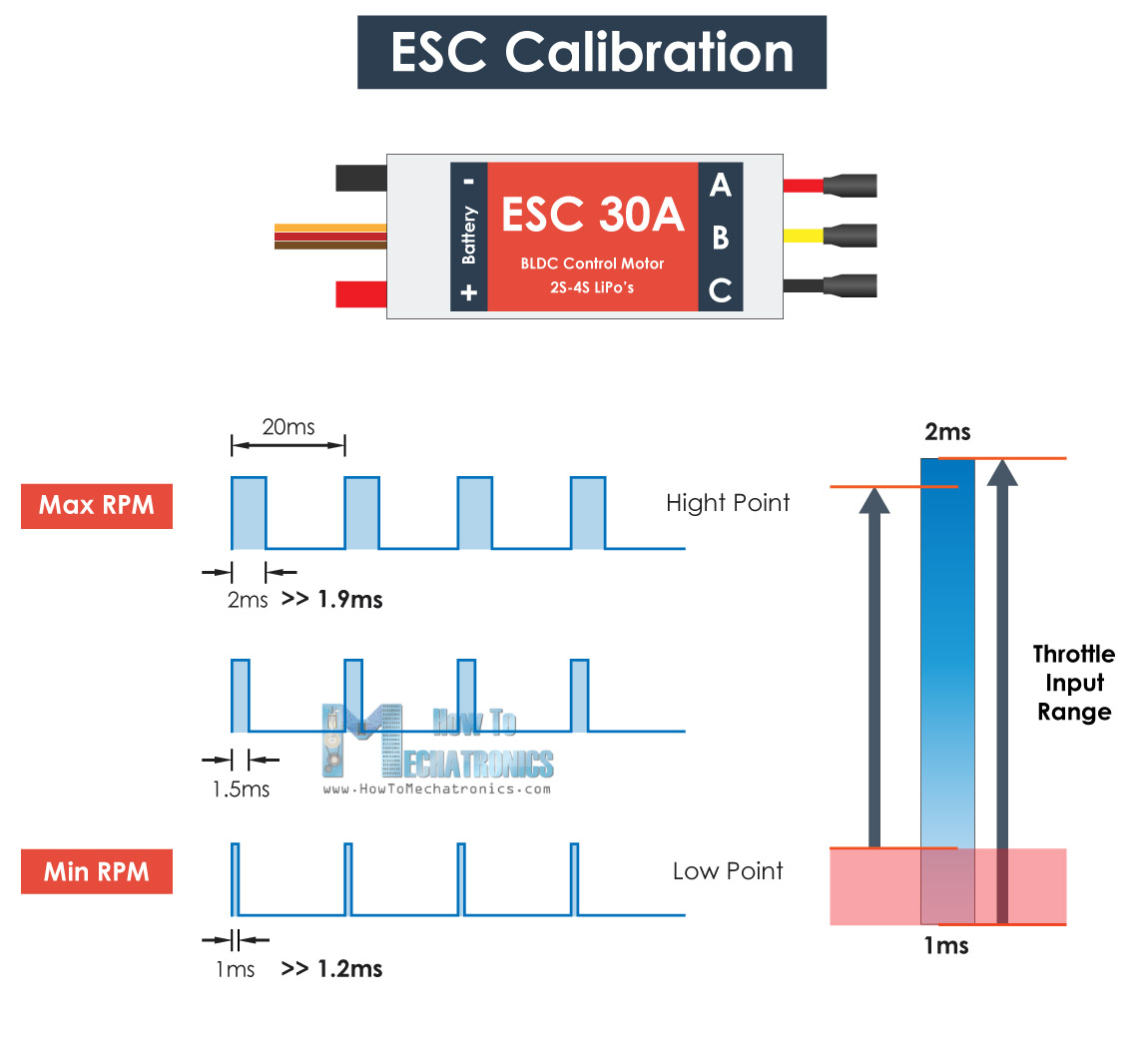
To solve this issue, we can calibrate the ESC or set the high and low points as we want. For that purpose, before powering the ESC, first we need to throttle up our potentiometer to maximum or a value at least greater then the current middle point. Then we can power up the ESC, and we will hear few beeps from the motor which actually confirms that we have set the new high point.
Then after 2 seconds, we should move our potentiometer to the position where we what the new low point to be. We will again hear the confirmation beeps and with that we are done with the ESC calibration. Now our throttle will respond right away and we can control the motor within these new two points.
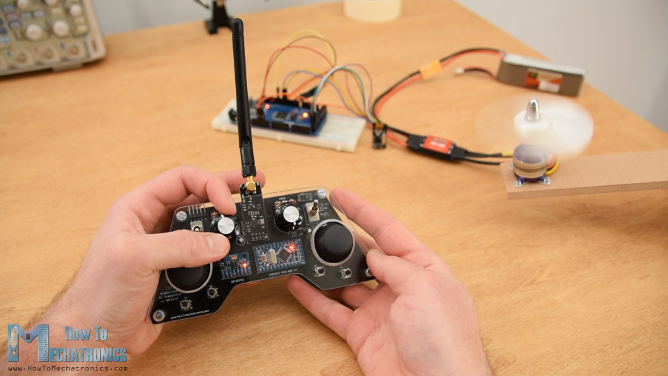
That’s pretty much everything for this tutorial. In case you want to learn how to wirelessly make this Arduino brushless motor control, you can check my previous video where I build and Arduino based RC transmitter and explained how to control BLDC motors using it.
I hope you enjoyed this tutorial and learned something new . Feel free to ask any question in the comments section below and don’t forget to check my collection of Arduino Projects.
I used this to install a high speed brushless motor with 50mm fan blades inside the defrost duct of my old CJ7 Jeep to reduce windshield fog. I was able to adjust the numbers in the code to limit the high end of the motor. I added the following two lines after ESC.attach so I do not need to turn the potentiometer off to arm the ESC every time I start the Jeep.
ESC.writeMicroseconds(900); // send “stop” signal to ESC.
delay(4000); // delay to allow the ESC to recognize the stopped signal
“The “S” number of a LiPo battery indicates how many cells the battery has, and each cell has a voltage of 3.7V.”
This is false, to a degree. S refers to the number of cells in series. A 3S2P battery has six cells, three in series and two in parallel. The pack therefore has three times the voltage of a cell and twice the capacity. In addition, NiMH, Li-Ion, and LiFePO4 all use the same S and P system, which you can find in battery packs in everything from airsoft guns to electric vehicles. Finally, lithium batteries are listed as either 3.6 or 3.7 volts, but this is actually the nominal voltage. A full LiPo will be 4.2v per S and an empty one will be 3v. While it is possible to go above or below these values, both will most likely cause permanent damage to the pack and all the cells inside (Though if it doesn’t cause a fire, there’s a chance the BMS will be salvageable if the pack uses one. Nevertheless, it should not be salvaged because they’re cheap and don’t risk it).
Greetings
I have a “Brushless Motor Driver for Polygon Mirror” taken from a Xerox Laser Printer. The board has 5 input pins: I suppose it is 24v, Gnd, 5v plus two signal pins and it uses a IC named HA13535. I would like to make it run; which circuit did you use to control?
I would like your help, please.Thanks
This is very helpful! Thank you.
BEC is wrong connected, BEC provides 5V (+ pin is an output) and the 5V pin of Arduino is an output too, that’s why nobody can do it.
Just don’t connect the + pin of the ESC, and connect to Vin pin of the Arduino or power the Arduino whit an USB cable.
Well you can use the 5+ pin on the Arduino as input, if you supply 5V. The Vin pin won’t work with 5V, as it has voltage regulator and can work with voltages from 7V to 12V, which will be dropped to 5V.
Hi, I wanted to use brushless motors as drive motors in the wheels for my robot but I cannot figure out how I can operate a BLDC in both directions, forward and reverse, using an ESC. Is there a way we can do that?
Hey, for that purpose you need a special ESC capable of driving the brushless motor in both directions. There are other methods that this can be achieved, for example using a relay. In such a case, you can connect the three wires through the relay in a way when you active the relay, the two wires of the motor switch place.
If I use 3S Lipo battery of 2200 mah for running a 1000kv BLDC motor, so how much backup can I have in term of time or how long the motor can run on this battery if their isn’t any load?
and what is the BLDC (1000kv) motor load in term of current?
I am really appreciated if you reply me back,
thanks.
You should make a V divisor in order to input the battery to an analog input.
Once it is done, you could check it in real time and add a low level warning or power off.
Hi, I am try to run 2212 BLDC motor with Arduino via ESC (simonk 30A), but having trouble while interfacing them. Sometime my BLDC motor run for a while and then stop. I realized that, when I power up the Arduino, so BLDC starts working but just for few sec and then back to stop. kindly let me know the solution for it.
The code I uploaded which is.
#include
Servo ESC; // create servo object to control the ESC
void setup() {
// Attach the ESC on pin 9
ESC.attach(9);
}
void loop() {
ESC.write(100); // Send the signal to the ESC
}
//I just want to run the motor that’s why I didn’t use the potentiometer here.
Thank you , it was so productive ,
I have two questions which I could not find the answer anywhere.
what is the relationship between RPM and PWM ?
for example if the Kv is 1000 and Lipo battery supplies 7.4 (v) we have a max RPM of 7400. I have read in lots of sources this it true when we have no load . so my question now is 1) what do mean by load ? is it the attached propeller to the motor ? if we have a propeller the max RPM is still 7400 ?
2) if we say the max RPM is 7400 . it means when we have for example 10% duty cycle we get a speed of 7400 RPM ???(like your case 2 millisecond which is equal to 10% duty cycle ) . and if it is true , we should define it in the code that ” for 10% duty cycle we get a RPM of 7400″ ???
I really really appreciate it if you can reply me back ,
thank you
1) That’s right, a load is anything that’s opposing the free rotation of the shaft. Different size propeller will have a different load, bigger propeller will grab more air which means more resistance which means bigger load.
2) In this case of controlling Brushless motors the RPM and the PWM are actually not related. The 20 milliseconds signal is just a standard signal which is used for controlling the RPM of the brushless motor. According to this signal the controller, the ESC, drives the brushless motor appropriately.
I’ve just found your website and I have to say, you do a wonderful job explaining things electro-mechanical!! I’ve been playing with basic RC planes and have read, seen, and watched many articles and videos on BLDC motors and ESCs. Either I was trying to pick up information too early (or too late) in the day or it finally just . . . clicked!! Well done, and thank you!!
Thank you, I’m so glad to hear this!
Thank you for your great Informations.
I have one question.
Which capacity does have your 3S LiPo battery? Is a battery with 1800mAh enough or should i take one with 2400mAh? The motor im gonna use is the Dapei XXD A2212 1000KV Brushless Motor with the 30A ESC if you need this information.
I’m excited about your answer. Have a good day
And now i got one more question 😉
What is the meaning of the code where you map it into 0 to 180? why did you choose that and not an other value?
Well for driving the BLDC motor we are using the servo library, which works with these values from 0 to 180. The values from 0 to 1023 is the analog read from the potentiometer, so we map that values into values from 0 to 180 and in that way we can control the BLDC motor speed from minimum to maximum.
The capacity doesn’t really matter for this basic example. Sure, you can use 1800mAh battery with that motor.
Great write up! But…. Your code section has an error in the comments that confused me. I had to look through the servo library docs to make sure even… but the section of your code that reads: “ESC.attach(9,1000,2000); // (pin, min pulse width, max pulse width in milliseconds) ” is wrong, its not in milliseconds, its microseconds! I was confused because I know the pulse widths aren’t suppose to be 1 and 2 SECONDS lol.
Thanks! Yeah, that’s true, I’ve just updated the post, thanks for the remark.
Hi, thanks for this perfect explanation.
i uses your code to control 200kv bldc with 120a esc both from racerstar and after trying the code it doesn’t work and it works only when arduino is connected to laptop via usb. and motor works in the two direction and stops in the middle of the potentiometer range.
Hey thanks! Well it seems that you don’t have a BEC to power your Arduino or it’s not working working or not connected properly. BEC provide 5V so you should connect it to the 5V and GND pins of the Arduino.
thanks for your reply..
the ESC provide BEC and it works and also i uses your codes to make my own remote by nrf so i realy appreciate your work and love these useful videos.
last problem is the calibration because each ESC has its own way to do that and there’s no many tutorial about it. should i use oscilloscope and then change the (1000,2000) in attach function?
Thanks for the tutorial ! I searched for a tutorial about that for a while, now there is one finally, thanks.
I connected everything like you show but it still doesn’t work from some reason –
sometimes it beeps like it should work (the good beep, not the error one) but then when I turn the penteometer it doesn’t work, but sometimes (with some values – usually around 60) it randomly does “work” – moving but staying in the same position ? like it’s “fighting” itself and trying to rotate but can’t
Many times it beeps just once (for about half a second) – I couldn’t find anything online about one single beep. Or no beep at all, or beeps like it should work, then immediately after it an error beep.
Then I tried to restart the board / reconnect to the computer / reconnect the battery and each time I do each one of these things, it reacts differently.
Here a few photos of the wiring, and a video when the motor is moving but not moving
https://imgur.com/a/C8dZlJC
Any ideas what can be the problem and how to solve it ? I’m trying to figure it out for so so long, still can’t get the motor to work :\ I’ll really appreciate any help, thanks !
Hey, something might be wrong with the ESC or the motor itself. As an example, I had a problem with my motor now working because one if it’s wire was fault/ cut in the middle of the wire in the plastic tubing. I though it was the ESC that was not working but it was a simple wire problem. Then I just removed the insulation and re-soldered the wire nicely to the connectors and everything was working. So my point it, try different ESC and motor, the method explained in this tutorial should work 100%.
First thanks for the fast reply !!
I rechecked everything, rewired and still doesn’t work :/ then I tried with a brand new motor (and new esc) – and wired everything again and doesn’t work at all, no beep or anything. (I tried also with fixed value for the motor, same result)
I’m using the exact same battery like yours (or just the same brand, with 3s), and arudino nano.
I’m so frustrated and hopeless.. I’m spending soo much time on that..
Is there any way to just check the esc or motor? maybe to somehow turn on the motor full speed, without code? or to just check the esc somehow ? I’m just so hopeless, don’t know what to do with that anymore
Thanks for the tutorial. Its very well explained. Detailed info about the component’s working and the step by step explanation of the code, really makes the whole topic easy to understand. I do have a couple of queries I was hoping you could clarify,
-Is there a command in arduino to turn-off/disarm the motor
-Is there a way to reverse the direction of the motor via the code.
Thank you, for your assistance!!
Thank you! Well for reversing the direction you would need a specific ESC that is capable of doing that. For disarming the motor with an Arduino command, you could use some kind of a relay.
Thanks for always posting such good content! I’m trying to run two brushless motors with two ESCs via bluetooth. I’ve been trying to combine this information with your tutorial on two DC motors and bluetooth. I think I’m having difficulty with the code for it though, as my ESCs aren’t recognizing the signal. Is there an important step I might be missing in transferring information via bluetooth to an ESC? Thanks!
Well first of all you must make sure that both the ESCs control and the Bluetooth communication work properly, by testing the separate tutorials. Once you know that they are working, then you should not have any problem combining them together. The values you are receiving from the Bluetooth should be simple used to control the ESCs. You know that you can always convert values to match your needs, for example if you receiver values from 0 to 255 from the Bluetooth, you can just convert them using the map function into values from 1000 to 2000, and so on.