In this tutorial I will show you how I built the simplest CNC machine with minimum parts possible and without using a 3D printer. That’s right. I’ve been using 3D printers for most of my recent projects because, of course, they are great for prototyping as we can easily make any shape we want with them. However, not everyone has a 3D printer, so therefore I wanted to show you that we can also make stuff even without the help of 3D printers or other CNC machines.
You can watch the following video or read the written tutorial below.
Overview
I will show you how I built this CNC machine by using just a single power tool, a drill, and several hand tools. The material that I used for this build used is 8mm MDF board, which is actually quite strong and probably more rigid than a 3D printed PLA material and at the same time it’s easy to work with.
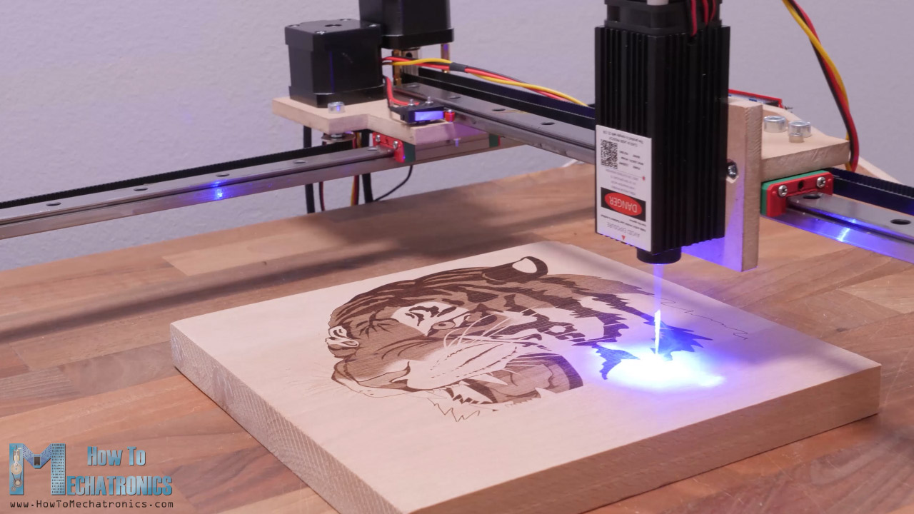
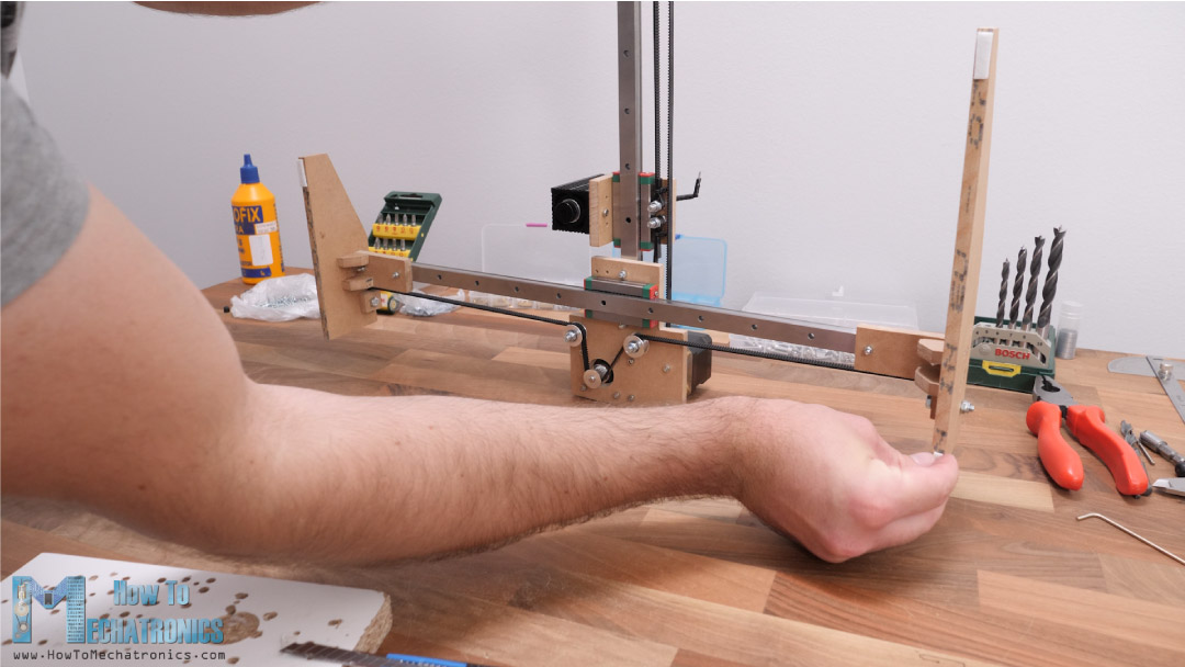
For this video I will use this CNC machine as a laser engraver, and in a future video I plan to make it work as a pen plotter.
Obviously, this type of construction of the machine cannot provide much rigidity so we cannot use it as a CNC router or a mill. Though, if we attach a more powerful laser, we could use it to cut various materials, like this MDF board that we are using here or other type of wood boards and with quite good accuracy.
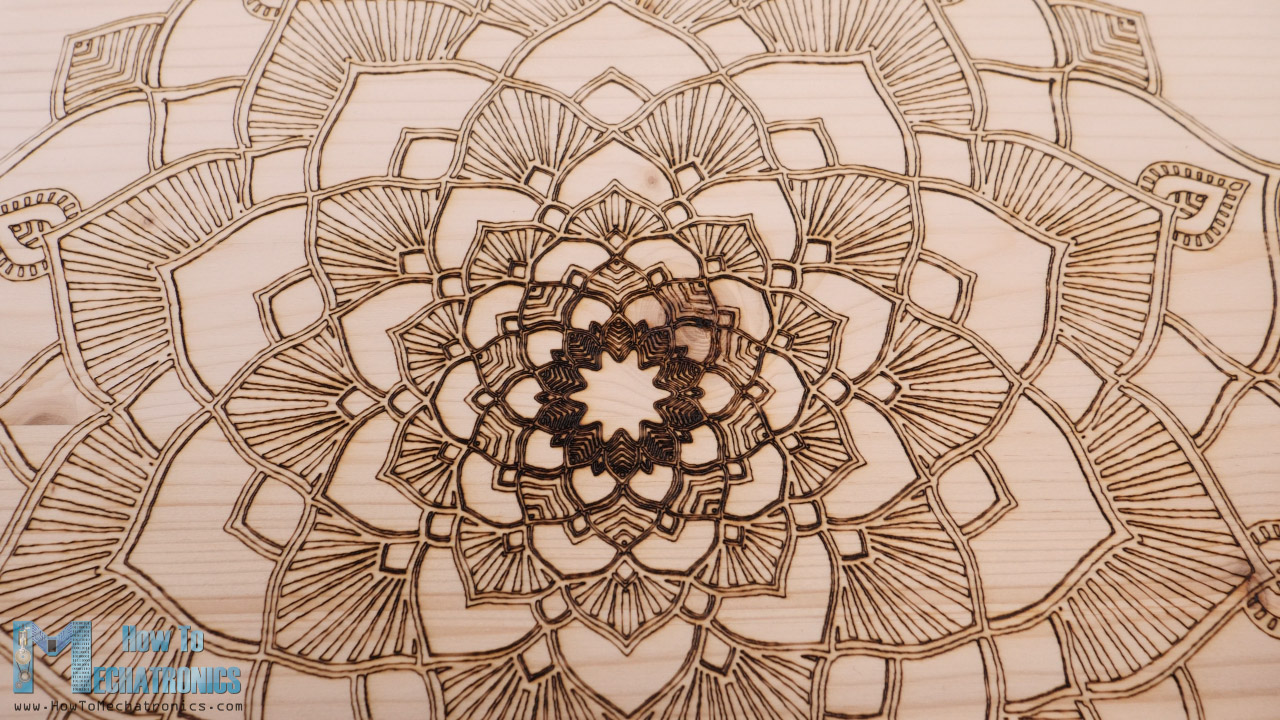
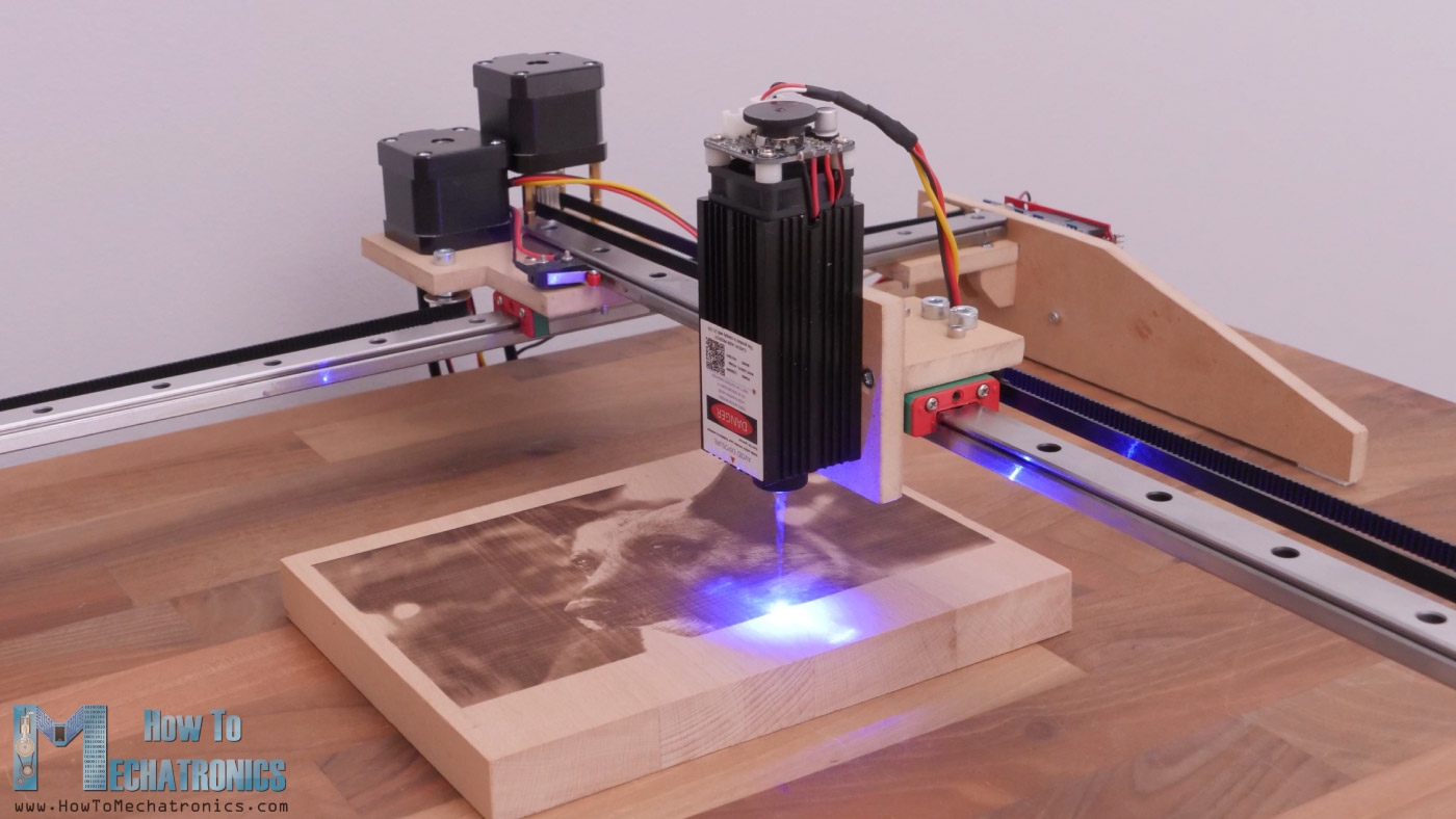
The working area of is quite big 390 by 360mm, and the level of details that this laser engraver can produce is pretty impressive. To be honest I was surprised how good the engravings turned out.
The brain of this CNC machine is and Arduino UNO board in combination with a CNC shield, but more details about that as well as how to prepare your drawings or images for laser engraving, make G-codes and control the machine using free, open-source programs, a bit later in the video.
DIY CNC Laser Engraver Machine 3D Model
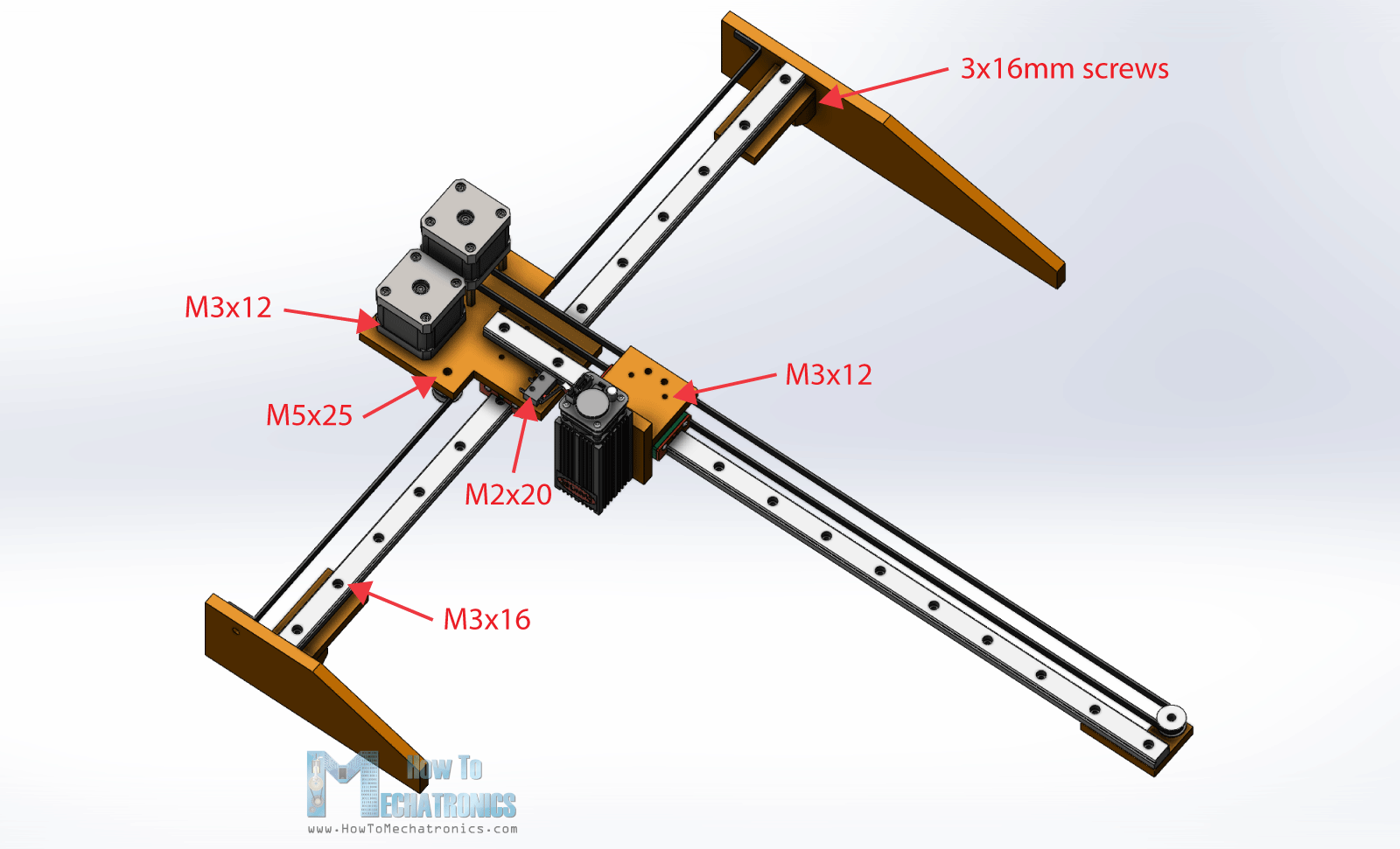
I started by designing the machine using SOLIDWORKS for Makers. The two main components of this CNC machine are these MGN15H linear rails together with their suitable sliding blocks.
For driving the blocks or the two axes, we are using two NEMA 17 stepper motors and some suitable GT2 pulleys and timing belts. For connecting everything together we are using 8mm MDF board, and for homing the machine, two micro limit switches.
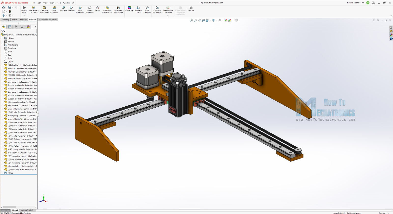
And that’s it, a CNC machine with minimum parts possible.
You can download the 3D model here:
You can find and download this 3D model, as well as explore it in your browser on Thangs:
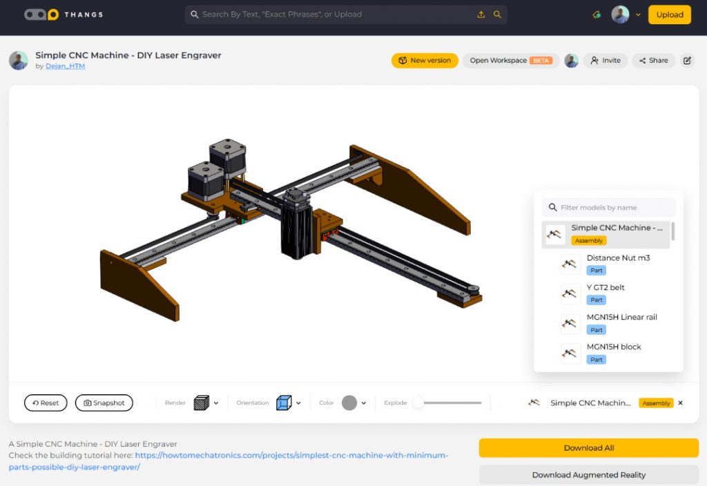
Download the assembly 3D model from Thangs.
Thanks Thangs for supporting this tutorial.
Here’s the drawing of the central mounting plate:
See also: Arduino CNC Foam Cutting Machine
Assembling the machine
All right, so now we can start building the machine. Here’s a list of components needed for assembling this DIY CNC machine. The list for the electronics components can be found below in the circuit diagram section of the article.
- MGN15H Linear Rail ………………………… Amazon / Banggood / AliExpress
- Stepper Motor – NEMA 17 ………….… Amazon / Banggood / AliExpress
- GT2 Belt + Tooth Pulley…………………… Amazon / Banggood / AliExpress
- GT2 Idler Pulley ………………………………… Amazon / Banggood / AliExpress
- Spacer Nuts …………………………….…….. Amazon / Banggood / AliExpress
- Bolts and Nuts set …………………………… Amazon / Banggood / AliExpress or from local hardware store + Flat Head Screws 3x16mm
- M2x20 x2, M3x12 x20, M3x16 x6, M5x25 x5, 3x16mm screws x20
Disclosure: These are affiliate links. As an Amazon Associate I earn from qualifying purchases.
Here’s the 8mm MDF board that I will use, and according to the drawings that I took from the 3D model, now I will cut the pieces to size.
Related: DIY Pen Plotter with Automatic Tool Changer | CNC Drawing Machine
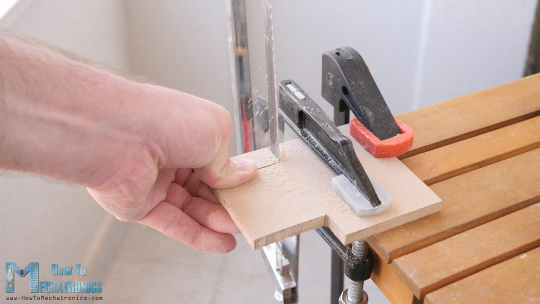
For that purpose, I used the simplest possible method, a pencil for marking where I needed to cut and a hand saw to cutting them.
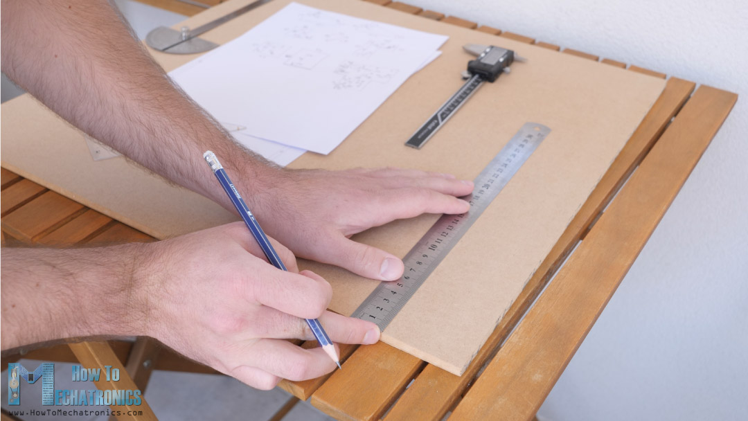
Of course, it requires some effort to cut all the pieces by hand, but still, we can get them pretty nice and clean even with this method.
Once I cut all pieces to size, I moved on with making the holes on them. Making the holes precisely is actually more important than cutting the pieces. The holes positions must be very precise as they have to fit with the other parts which have precise and fixed dimensions, like the linear rails and the stepper motors.
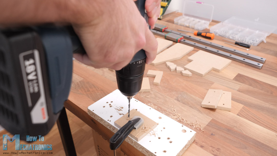
The central plate where the Y-axis and the stepper motors are mounted has many holes and in order to get them right, I printed a drawing of that part in real size.
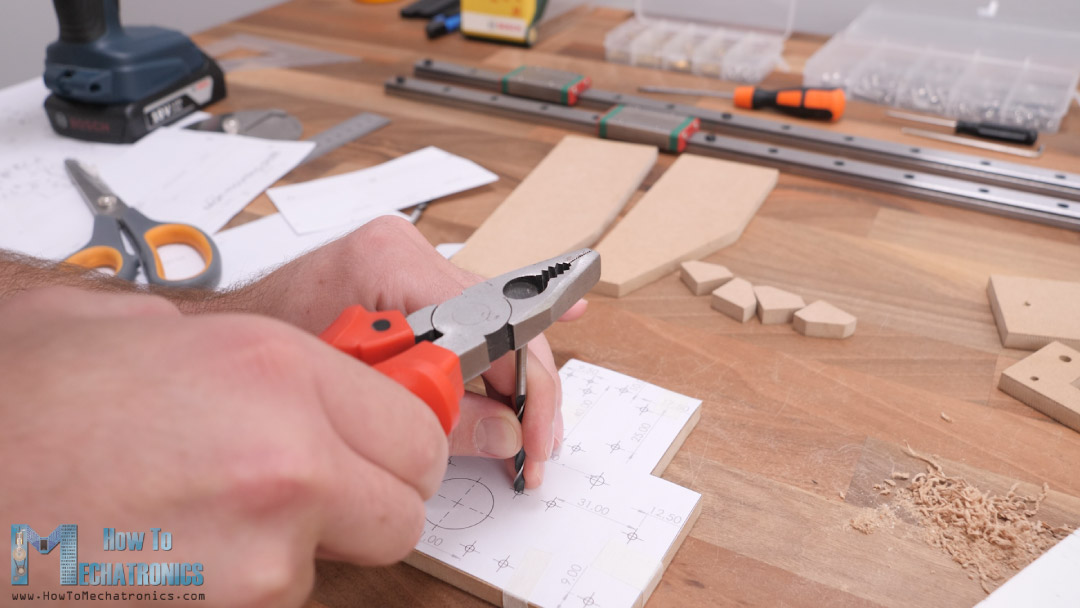
Normal printers are easily accessible to everyone, so I though it won’t be a cheating if I used one for building this project. In this way we can position the part and the drawing and mark the locations of the holes. Then we can drill the holes, although this doesn’t mean that we will get them 100% accurate. We are still doing the job by hand, so we have to be very concentrated and patience to get them right.
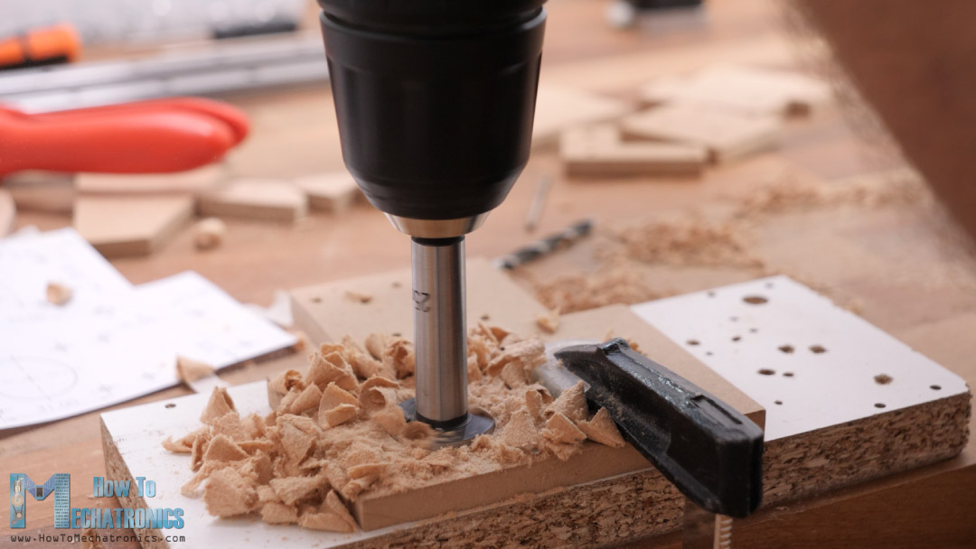
We need 3 and 5mm drill, as well as one 25mm drill for making the opening for the stepper motor.
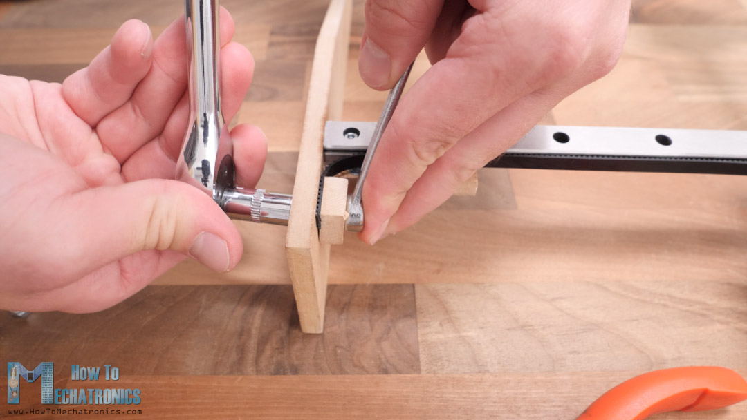
Next, I continued with assembling the base of the machine, on which the X-axis rail will be secured. For that purpose, I marked the position where the rail support part should be fixed, and drilled two holes on the base part, and one hole on the support part.
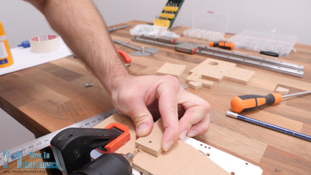
Then I secured these two parts with the first 3mm screw and some wood glue. With the first screw in place, I checked for squareness and then pre-drilled the second hole on the support material with 2mm drill.
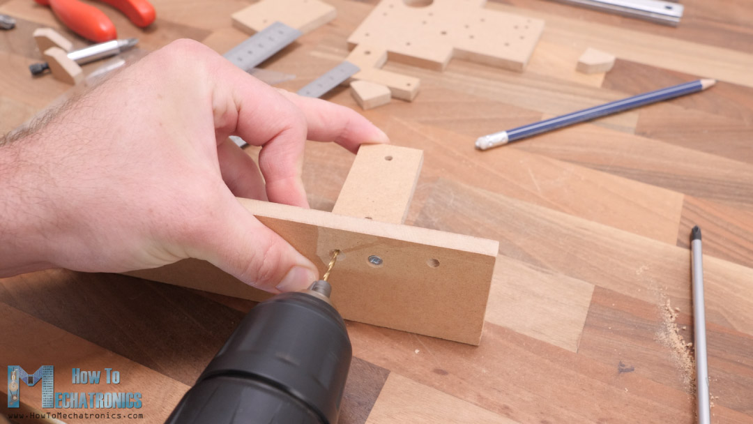
In similar way, I added two brackets for better support.
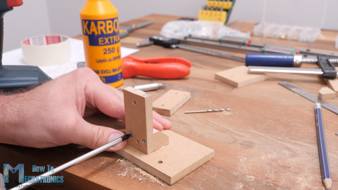
To be honest, this method of assembling these MDF parts is not that good, as it’s really hard to get them square as everything we do is by hand and the MDF boards are just 8mm tick which additionally complicates this process. Maybe a better and easier way would be to use metal brackets which you can easily find them in a hardware store.
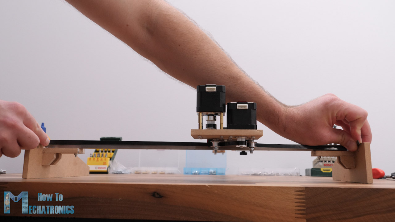
Nevertheless, once I had the two sides ready, I installed the X-axis rail to them.
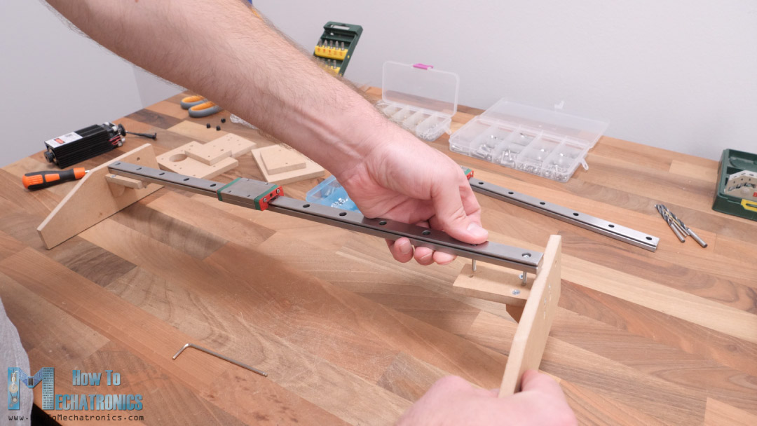
These MGN15H rails provide very smooth and play free movement, as their sliding blocks have balls or rollers inside them.
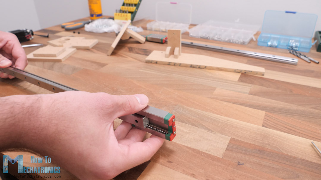
Before installing them, we should clean and grease them well. I secured the linear rail in place with two M3 bolts on each side.
Next, we need to install the Y-axis on top of the X-axis sliding block. For that purpose, we will use the central plate.
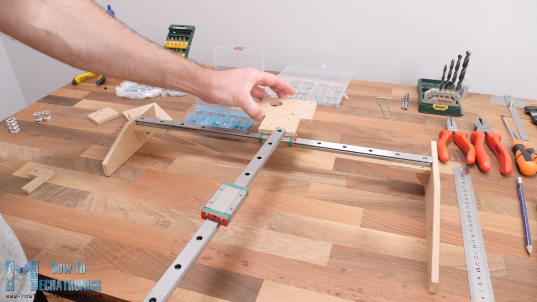
Again, we are using M3 bolts for securing the parts together. For securing the stepper motors in place we also need M3 bolts.
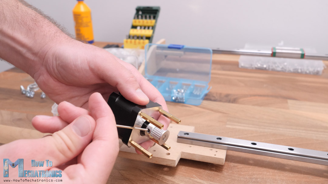
In addition to that, for one of the steppers I’m using some distance nuts in order to get a proper mounting height for it, though I probably could have mounted this stepper at the bottom side of the plate and so we would have to use those distance nuts.
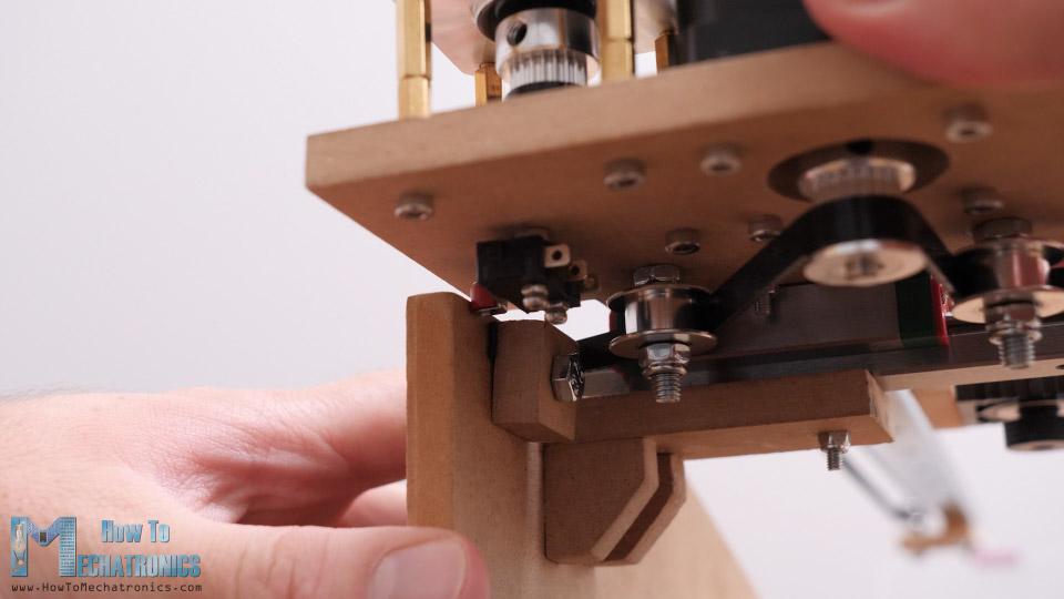
For driving the X-axis, we need to install two GT2 idler pulleys near the stepper shaft so that we can create a proper tension between the belt and the stepper pulley.
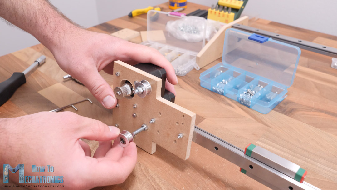
We need M5 bolts and nuts for securing them. As for the Y-axis, we need only one idler pulley on the other side of the rail, as the belt for this axis will be installed in a loop.
All right, so next is the marriage or connecting the X and the Y axes rails together. We do that using four M3 bolts. This connection is crucial to be precise as the precision of the whole machine depends on it.
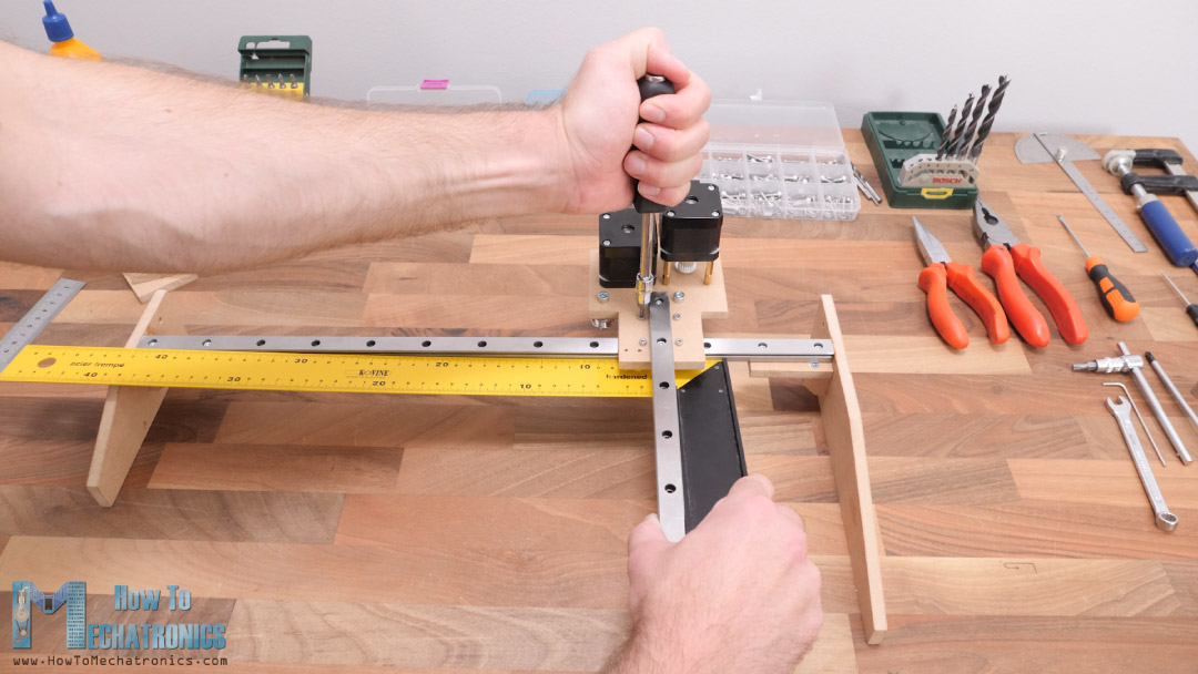
Using a square ruler, we must check whether the two axes are perpendicular to each other, and if not, we should adjust them properly.
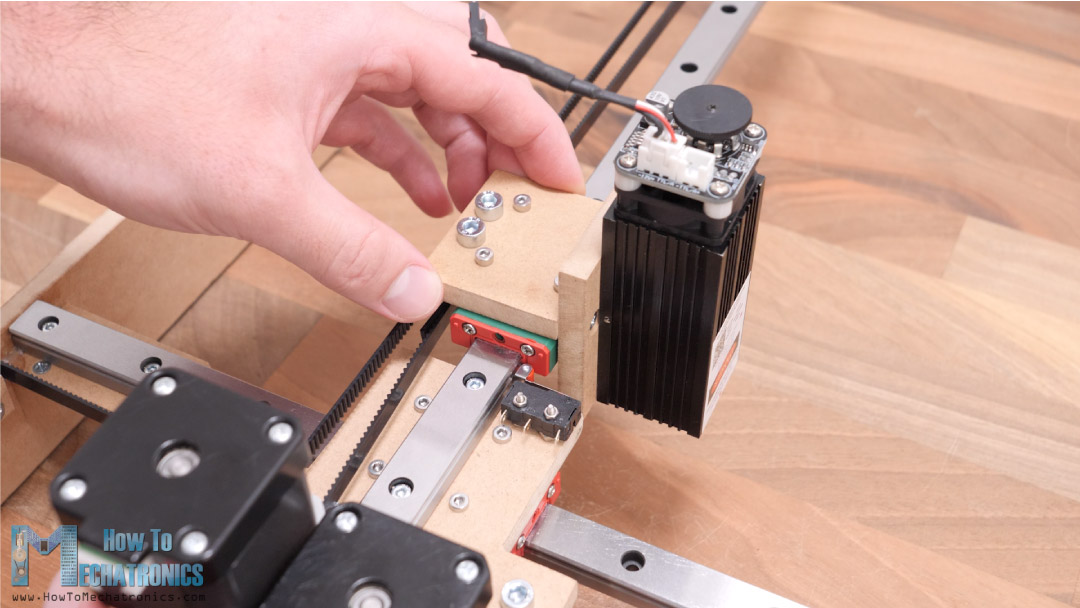
Next, we can install the parts which go on the Y-axis sliding block and actually hold the end effector or the laser module in this case. Using the method explained earlier, I assembled these parts and secured them to the sliding block using four M3 bolts.
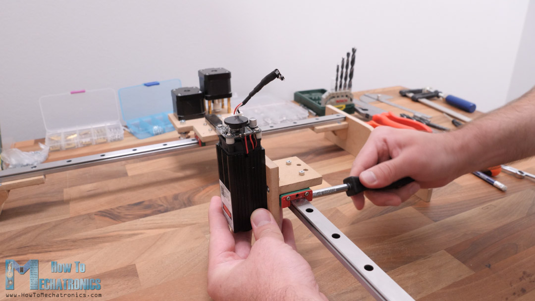
Now we can secure the laser module in place with two M3 bolts.
I continued with installing the GT2 belts. I measured how much length I need and cut the belt to size.
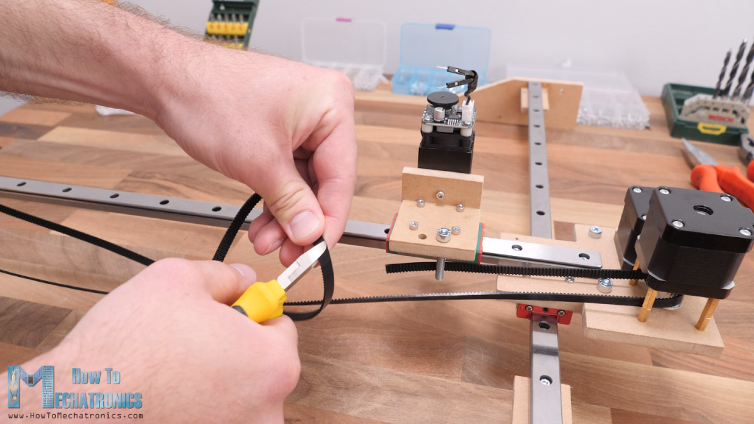
For securing the belt to the sliding block I used two M5 bolts and zip ties.
I secured the first side of the belt to the M5 bolt with a zip tie, and then tensioned the belt on the other side and secured it to the second bolt with the zip tie.
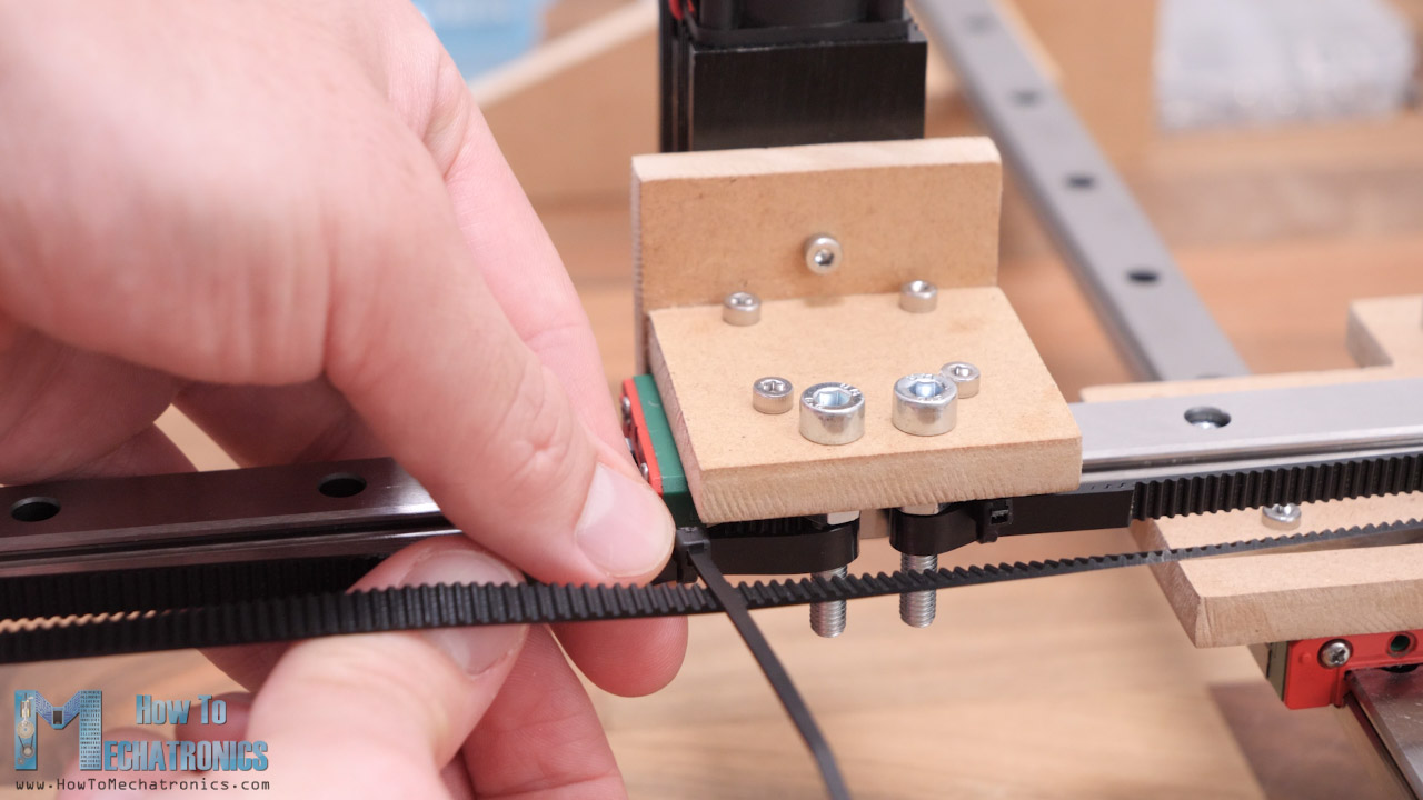
As for the X-axis, the belt will be stretched in line from one to the other side while passing through the three pulleys in a way that will provide tension or grip with the stepper motor pulley.
I secured the belt on both sides with a single bolt and square MDF piece.
With this our CNC machine is almost done. There are few more things that we need to do.
At the bottom side, I glued some furniture pads so that the machine stays more firmly in place.
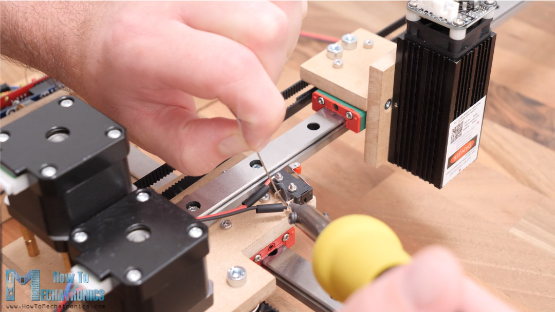
Then I installed the micro limit switch for the Y-axis. We need two M2 bolts for that purpose.
As for the X-axis limit switch, I forgot to make those holes on the central plate, so I marked them and drilled them on site.
It was a bit tight securing this limit switch in place but at the end it came out well.
Connecting the electronics components
The mechanical part is now completed, so we can move on with connecting the electronics components. As I mentioned, we will use an Arduino UNO board in combination with a CNC Shield and two DRV8825 or A4988 stepper drivers.
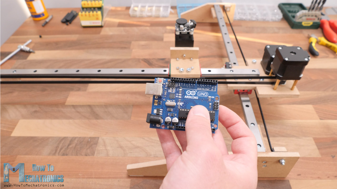
I will secure the Arduino board on the side of the machine, so I mark two Arduino holes and drilled them with 3mm drill. I used a 5mm distance nuts between the side panel and the Arduino board.
Read more: Stepper Motors and Arduino – The Ultimate Guide
The CNC shield simply goes on top of the Arduino board. We need to insert 3 jumpers for each driver so that we have the highest stepper resolution selected.
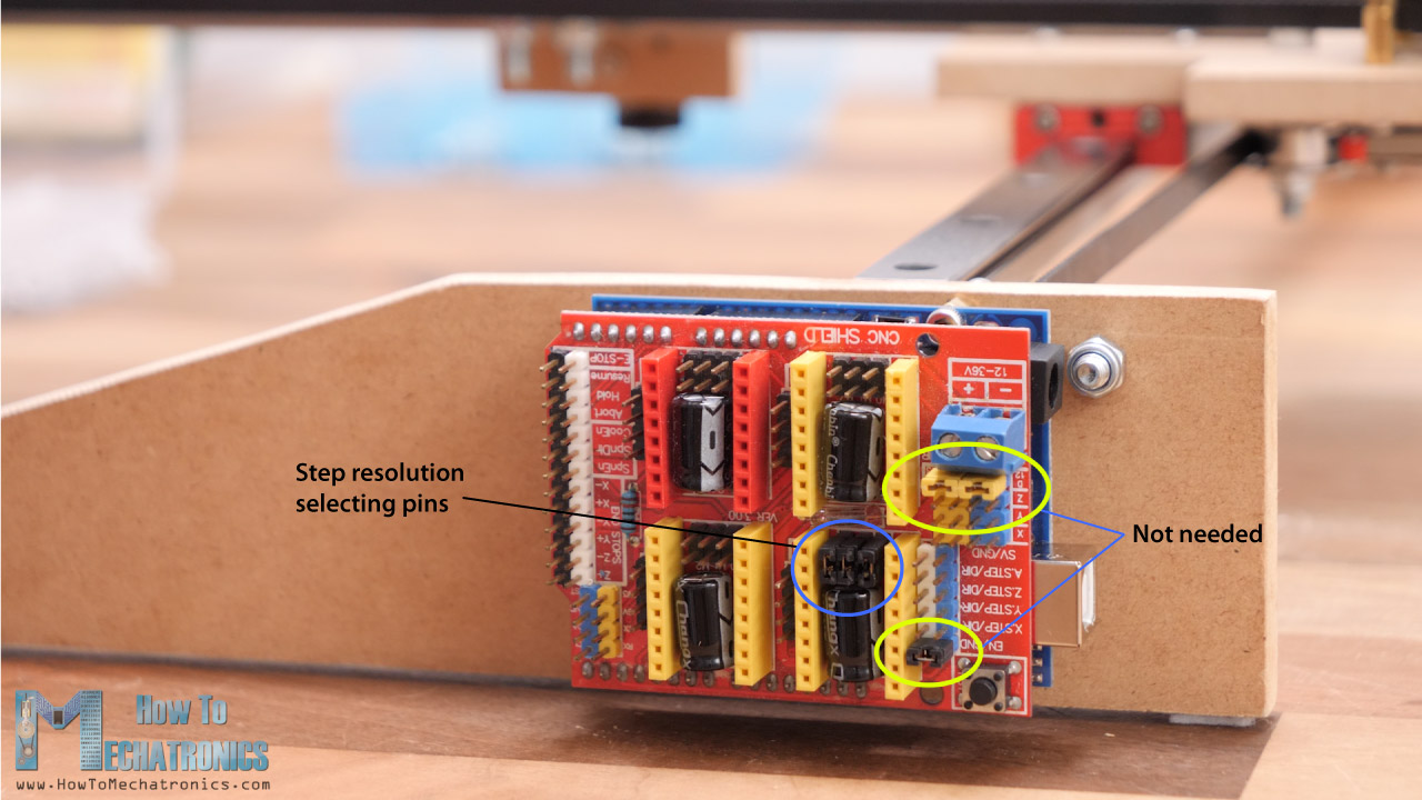
Please note here that these three jumpers should be removed as we don’t need them. I used them in one of my previous projects.
Then we can connect the stepper motors in place with the provided cables. For connecting the limit switches, we need two wires connection.
I soldered the one end of the wires directly to the endstops, and on the other side I soldered female pin headers so I can easily connect the to the CNC shield.
As for connecting the laser module, we need 3 wires, GND, 12V and a signal line for a PWM control. These wires need to be a bit longer so they can reach the farthest point of the machine.
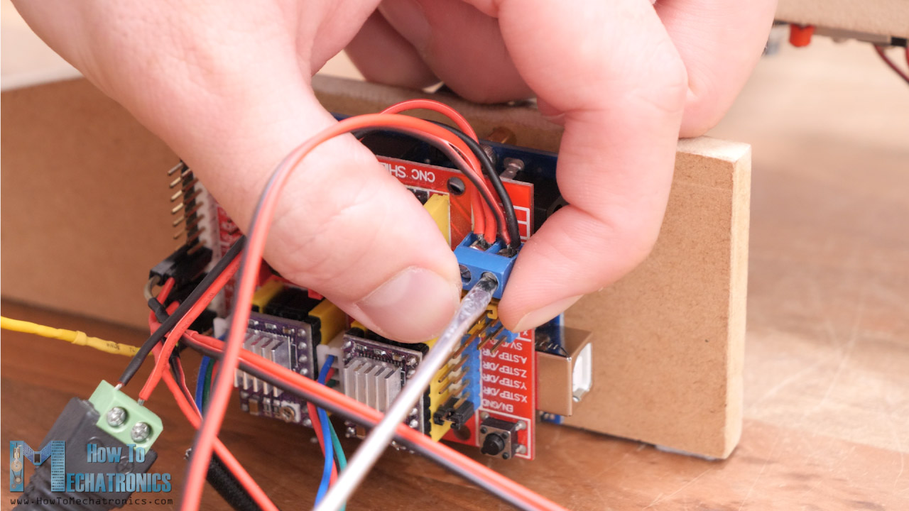
On one side we have the 3-pin connector that goes in the laser module, and on the other side we have the GND and 12V wires that will go to the power supply connector of the CNC shield and the signal line that needs to be connected to the Z+ or Z- endstop pin.
DIY CNC Laser Engraver Circuit Diagram
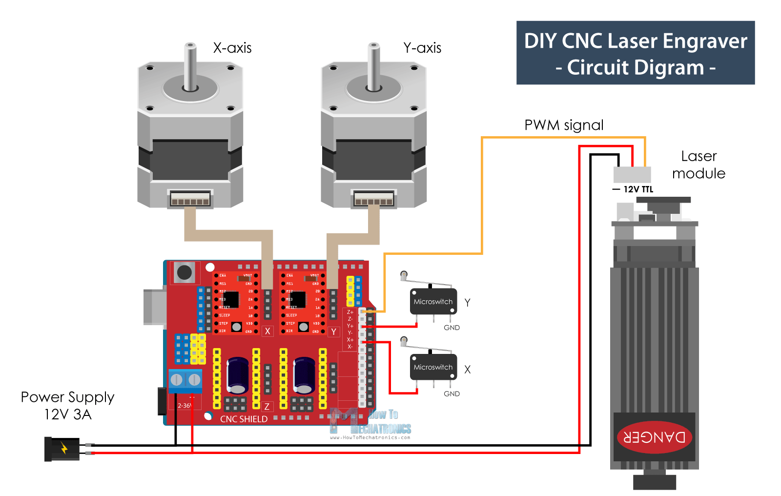
Here’s the circuit diagram of how everything needs to be connected.
You can get the components needed for this project from the links below:
- Stepper Motor – NEMA 17……………… Amazon / Banggood / AliExpress
- DRV8825 Stepper Driver……….……..… Amazon / Banggood / AliExpress
- Arduino CNC Shield ………………………. Amazon / Banggood / AliExpress
- Arduino Uno………………………………..… Amazon / Banggood / AliExpress
- Limit Switch …………………………………. Amazon / Banggood / AliExpress
- DC Power Supply …………………………. Amazon / Banggood / AliExpress
- Laser Module ………………………………. Amazon / Banggood / AliExpress
- Laser Safety Goggles …………………….. Amazon / Banggod / AliExpress
Disclosure: These are affiliate links. As an Amazon Associate I earn from qualifying purchases.
So, we are using an Arduino UNO board in combination with a CNC Shield and two DRV8825 or A4988 stepper drivers. We have two micro limit switches for homing the machine and a 12V Laser module which can be PWM controlled. For powering we need 12v power supply with a minimum current rate of 3 amps.
Firmware and Control Software
With this, we are actually done with assembling the machine. What’s left to do now is to give life to it or make it a real CNC machine. For that purpose, we need to install a firmware to the Arduino for controlling the motion of the CNC machine.
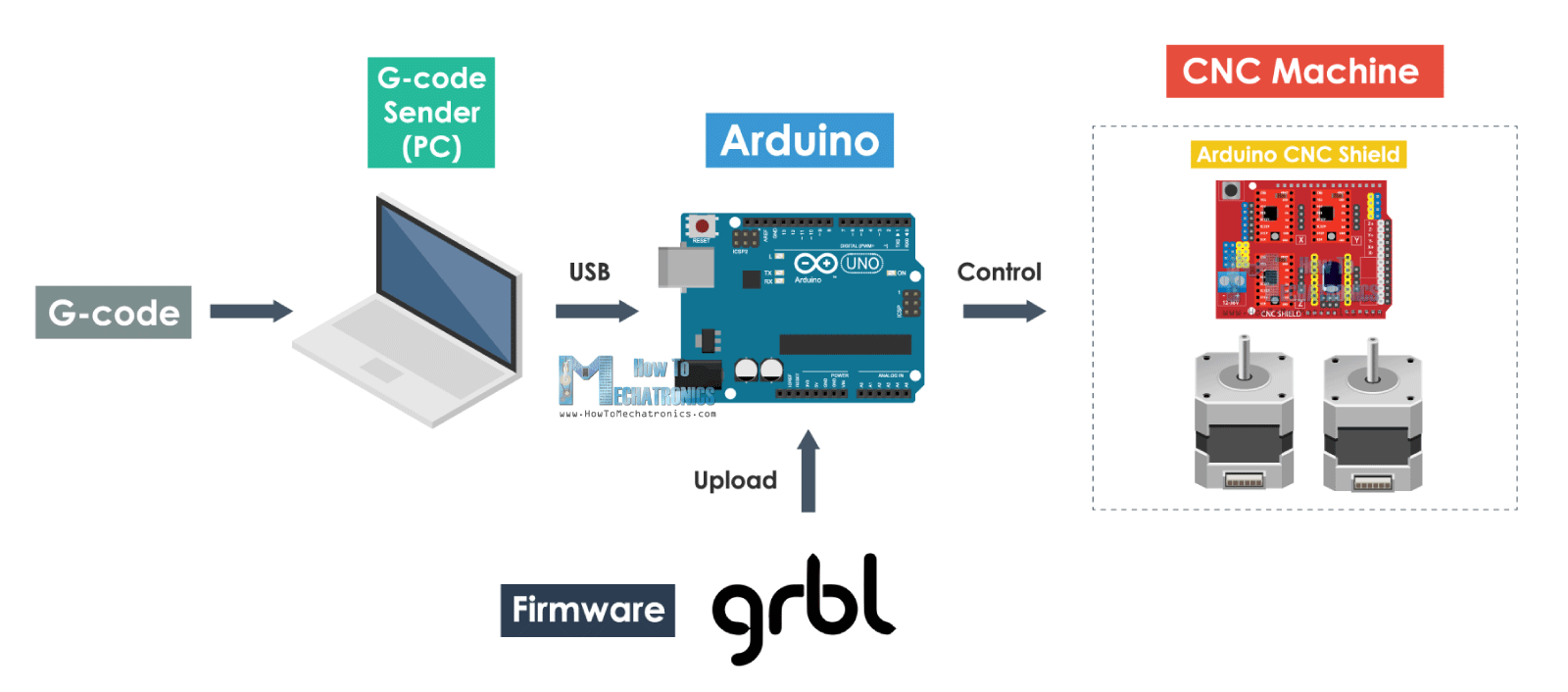
The most popular choice for DIY CNC machines is the open source GRBL firmware. In addition to the GRBL firmware, we also need a control software through which we will send G-codes and tell the machine what to do. In this case we will use the LaserGRBL controller. This software is specifically made for controlling laser engravers with the GRBL firmware, and I can tell you that it’s really an amazing controller for that purpose considering it’s also open source.
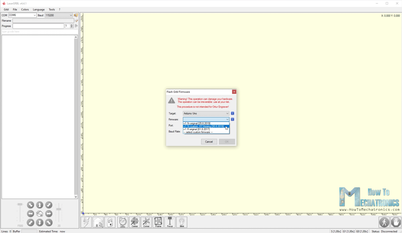
With LaserGRBL we have an option to directly flash or upload the GRBL firmware to the Arduino so we don’t have to do that manually. We can even choose a ready to use version for two axis machines with just X and Y homing, just like the one we need.
So, once we flash our Arduino with the GRBL firmware, we can connect our machine with the controller and open the GRBL configuration window so we can adjust some parameters according to our machine.
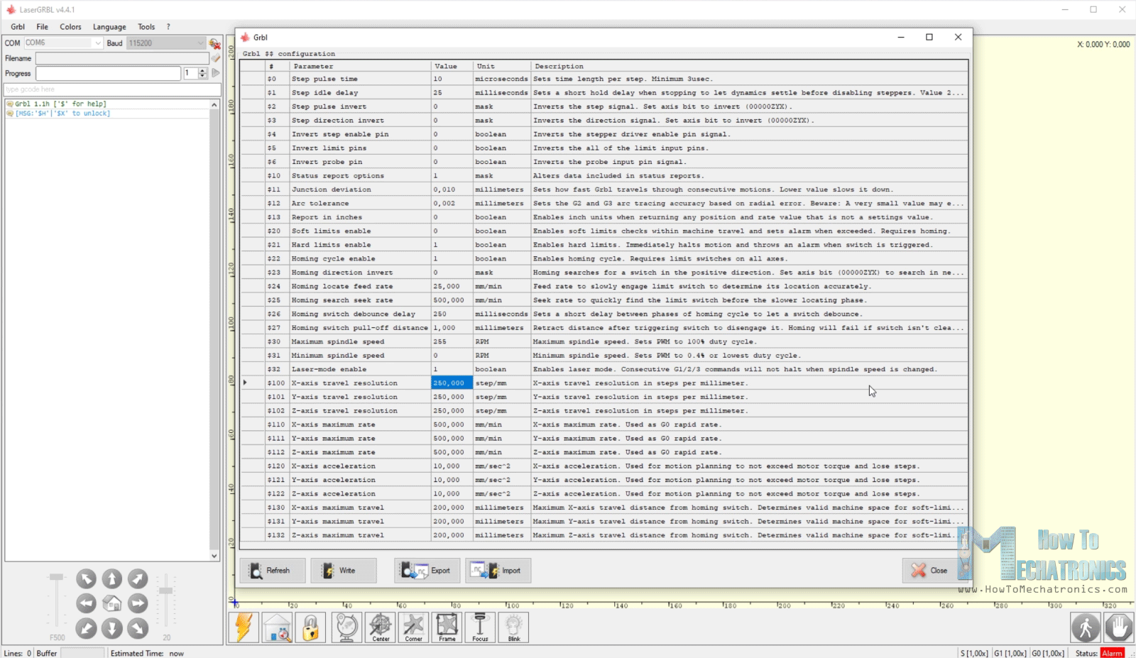
The first thing that we should adjust here is the travel resolution or the steps/mm values for the X and Y axes. These values indicate how many steps the motor should take in order to move 1mm. This depends on the type of stepper motor that we have, the selected step resolution and motion transmission, in this case the GT2 belt and pulley.
Here’s how we can calculate these values for our machine. The default values here are usually 250 steps/mm. Now we can move the machine using the JOG commands, for example 20mm, and we should notice how much the machine will actually move.
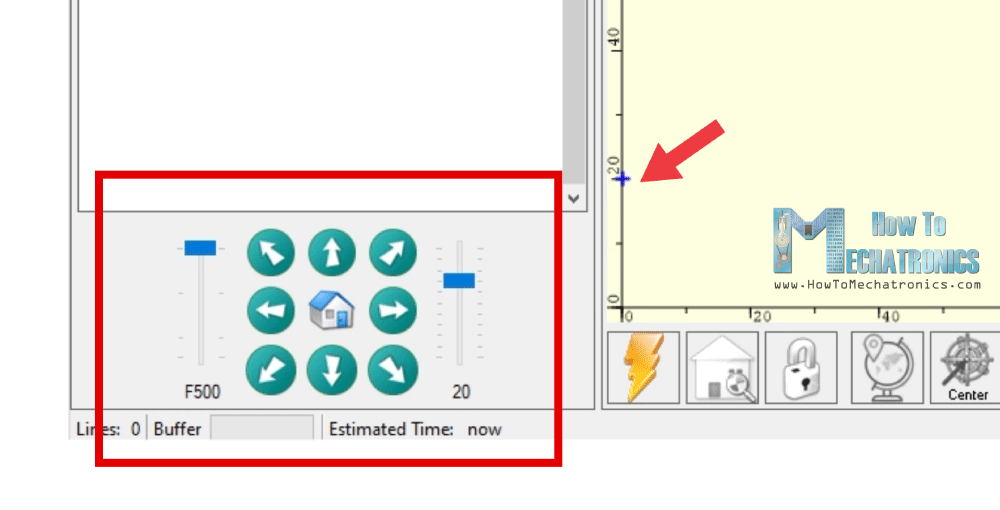
In my case, for 20mm jog on the Y-axis, the actual movement was 31mm.
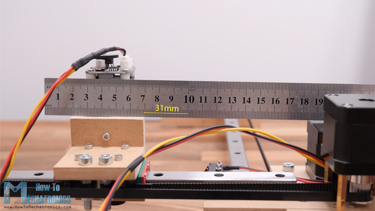
So, 20/31 = 0.645, and if we multiply that value with 250, we will get 161.29. So, that’s the value that we should set as a steps/mm value for our machine.
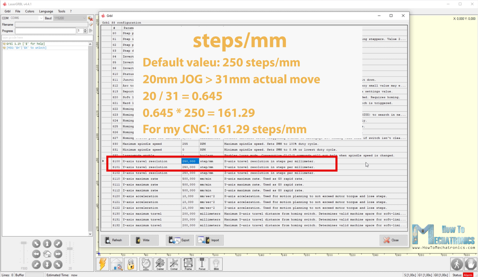
If we try to move the machine now with the updated values, the machine should move the exact distance. If you are not happy with the result you can still fine tune these values by drawing squares and measuring them. I ended up using a value of 160 steps/mm.
Nevertheless, there are other important parameters that need to be adjusted as well. For example, we should enable Hard limits which are the actual limit switches, Soft limits which defines the working area, set the Homing direction which defines where our limits switches are located on the machine and so on.
You can download my set of parameters so you can just import them into your firmware.
Generating G-codes for Laser Engraving
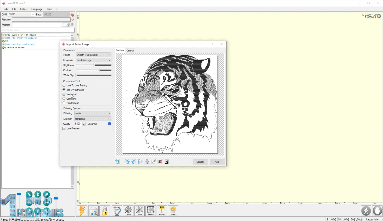
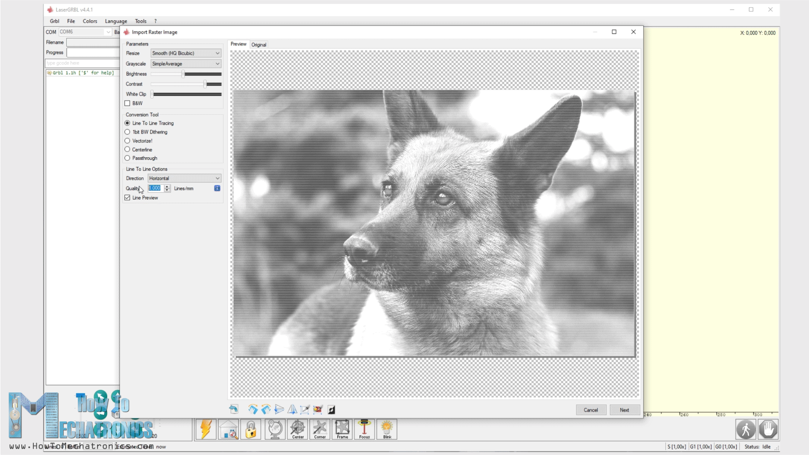
Another great thing about this software is that it also has a built-in G-code generator. This means that we can load any photo, clip art, pencil drawing and so on, directly into the software and we can generate a G-code for engraving according to our needs. The rastering image tool is quite versatile with many options to choose like, selecting Line to Line tracing, Vectorizing, 1bit BW Dithering etc.
Of course, if you want you can also generate G-code with other software, like for example Inkscape and its plugin Inkscape-Lasertools for generating G-codes and load them here. I already explained how to use this method for generating G-codes in my previous video, for the SCARA Robot laser engraver, so for more details you can check that video out.
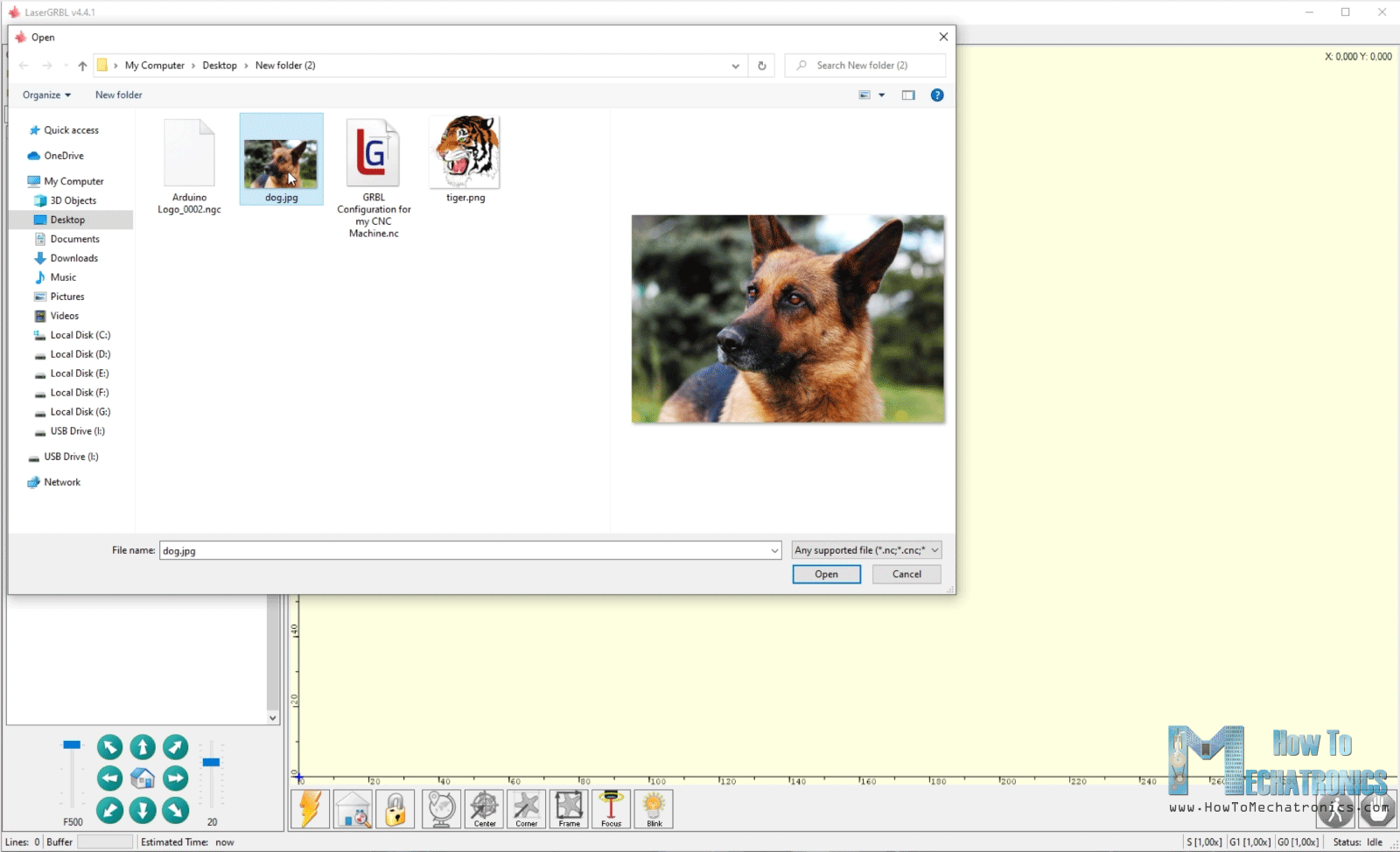
Now I will show you how you can generate a G-code for laser engraving from a photo using LaserGRBL. Here I have a photo of a dog, which I will open with the software.
Using the Brightness and Contrast option we can adjust the image to our desire. We can choose the type of conversion of the photo, for example, Line to Line tracing, 1 bit BW dithering or a vector format. I will use Line to Line tracing for this photo and here we can also select the line direction and the quality of the engraving which is defined by how many lines per mm there will be.
Next, we can select the Engraving Speed, set the minimum and maximum PWM values for the laser power, and set the size of the engraving.
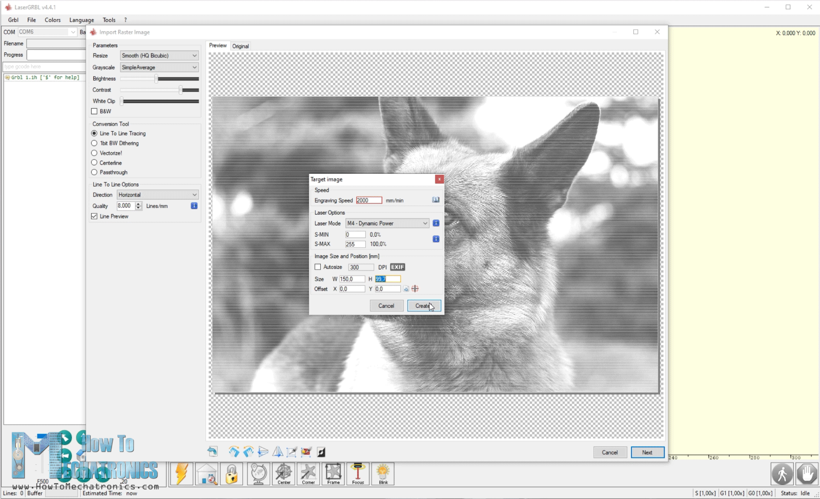
And that’s it, the software will generate the G-code for this engraving. Before we start the it, we can use the Frame button to outline or show us where the engraving will take place, so we can adjust our work piece as needed.
Please note that we must use laser safety goggles that will protect our eyes from the ultraviolet light of the laser, as it’s very dangerous.
If we have calibrated our machine correctly, we can get quite good engravings. For calibrating we could use this image that I made which has squares from 100% to 10% transparency.
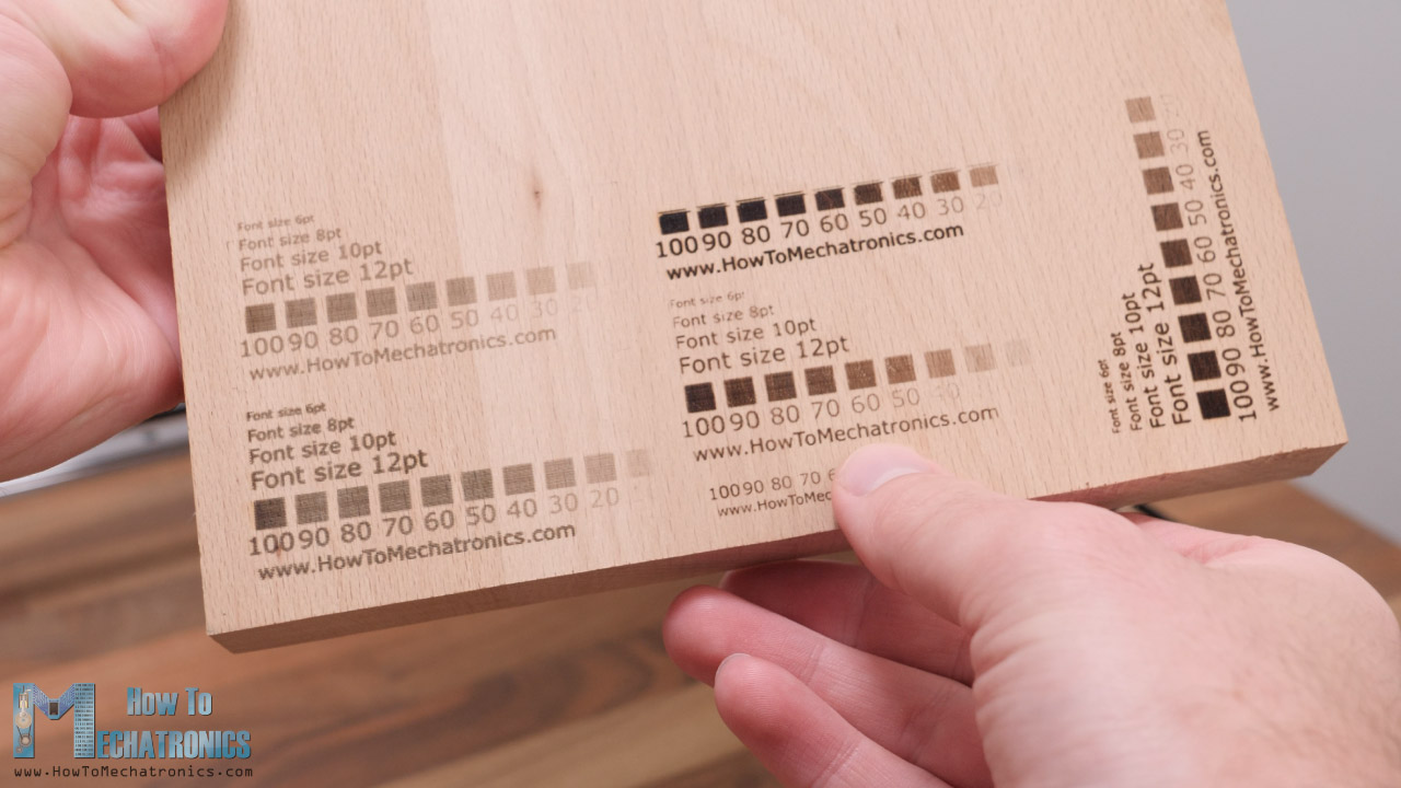
According the results adjust the engraving speed and PWM value for the laser power.
Here you can download the calibration image:
So, that’s it for this tutorial. I hope you enjoyed it and learned something new. If you have any questions feel free to ask the in the comments section below and don’t forget to check some of my other Arduino Projects.
Hi, first of all, thank you Dejan for all your effort. Every single project you made is literally awesome. Keep doing amazing things.
I have a question: did you use stepper NEMA17 59 Ncm or is 45 Ncm enough?
Hi, thank you!
45Ncm is enough, the isn’t any significant resistance with this setup, just the laser moving around on those sliding rails.
Thanks for the answer. Can you tell me how long is the linear rail in your video? Is it 500 mm? Sorry if you already mentioned it.
Sure, no problem. Yes, the rails I used are 500mm.
I really liked this project. I’m 14 and I built one, so, Dejan you should be proud of me. I think. Well thanks a lot for sharing this project free of charge. In addition I like that since this website is still kind of small you can actually read all your comments. Thanks!
I’m so happy to hear this. Have fun building more projects!
Cheers, Dejan
Hi, very impressive!
Is there a reason for not implementing a 12mm rails instead of 15mm ones? Maybe it’s for the excessive weigth of motors group to bear?? Is it for improve robustness of system? I am trying to re-engineer the project as a challenge of mine, without just copy in all and for all you though Picasso one said: “Good artists copy, great artists steal” XD
Thank you! xD
Well considering that even with the 15mm ones, this particular construction with one side of the Y-axis not being support, the 12mm ones would make the Y-axis bend even more. If you use one more rail to support the Y-axis on both sides, then even something smaller would be fine.
Than you! I was just thinking of adding a linear rod with linear bearing as support for the cantilever y-axis
Wonderful project! The structure of the CNC mechine much more easily than SCARA robot. I think DIY the CNC mechine will be suitable for more people.
Thank you! Yeah, it’s definitely much easier to build it than the SCARA robot.
Greetings. I’m in Brazil, your website and YouTube channel are very nice and instructive. congratulations.
I have a doubt; Could it be mounted with a laser to engrave stainless steel? and which would you indicate? Thank you.
ps. translated with google.
Thank you! Well the particular laser module that I used cannot engrave stainless steel. You need suitable and more powerful laser for that purpose.
On your DIY laser build, when you download the plans could you please tell me what app opens the file after download please. When I download and try to open the file, it tells me to use the play store to search for an app.
Thanks for any help.
Regards
David
The 3D model is a .STEP file which can be opened with various 3D Modeling software, like Solidworks and Fusion 360, and many other.