
In this tutorial I will show you step-by-step how I built this all-aluminum DIY CNC router that I machined with the help of my DIY 3D printed CNC router from my previous video.
That’s right, I machined all the parts for this CNC build, out of aluminum using my DIY 3D printed CNC router.
Then I disassembled it, and build this one using the same components, the aluminum extrusions, the linear rails, ball screws and the motors, so that we can make a direct comparison between the two CNC machines.
The 3D printed version was already quite rigid and capable of cutting aluminum with high accuracy within 0.05mm, but how much improvement we will get by replacing all 3D printed parts, with aluminum parts, can we get down to 0.02mm accuracy, can we cut steel with it now and how accurate it would be with it?
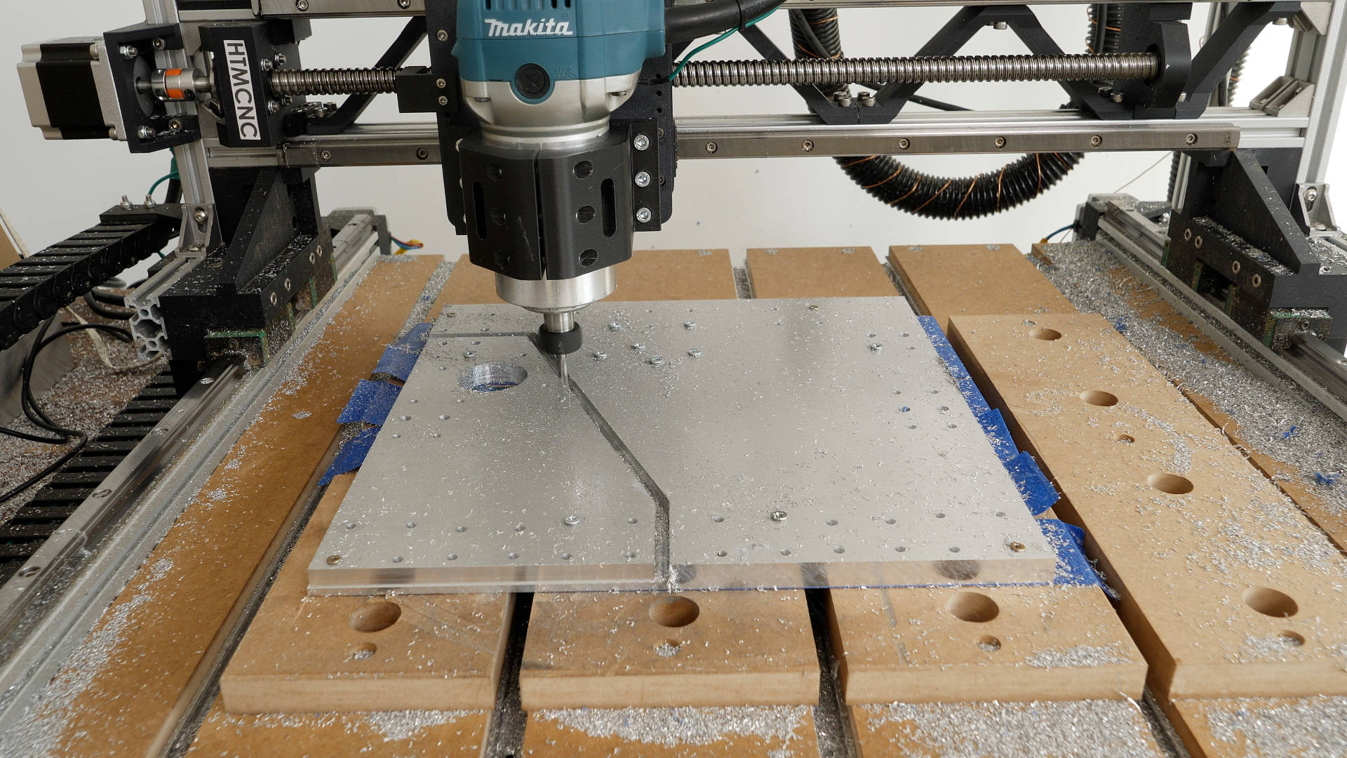
Well, here’s how it looks cutting aluminum with 5mm DOC, 1.2mm WOC, at 3000 mm/min feed rate. It literally eats the aluminum, and with a finishing profile pass, I got the accuracy of part within 0.02mm in the X and Y direction.
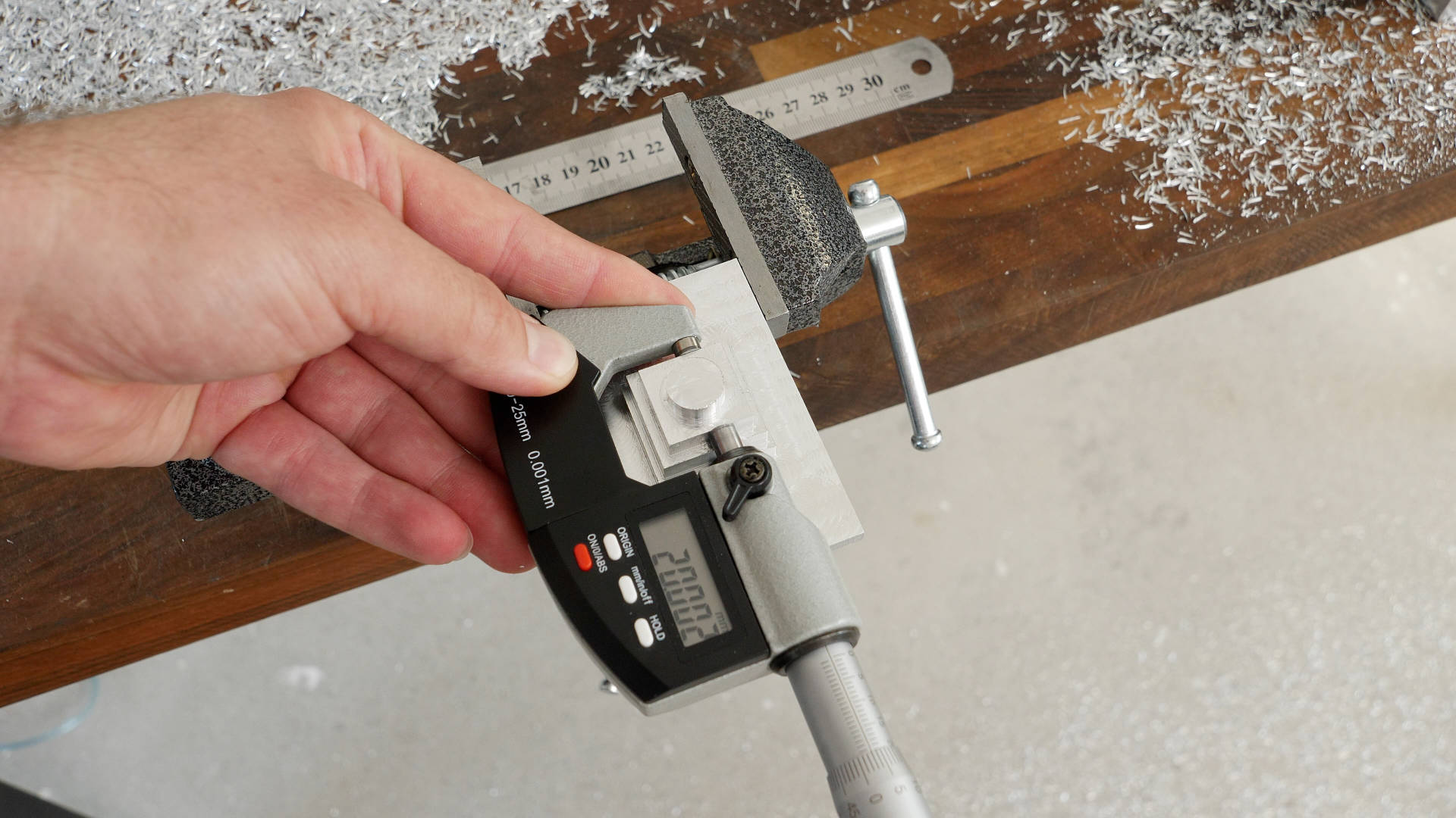
And as for steel, here’s how it looks cutting steel with 2mm DOC, 0.4mm WOC, at 800mm/min feed rate. Cutting steel is much harder and complicated than cutting aluminum. It needs suitable cooling and spindle RPM and torque, which this hardware store Makita router certainly doesn’t have. But still, after the finishing profile passes and with some appropriate profile offsets, I managed to get the steel part within 0.03mm of the target size. If I may say, that’s pretty impressive for a desktop DIY CNC machine, which can be built relatively easy if you follow this step-by-step guide.
3D Model and STL Download Files
You can view the 3D model of this DIY CNC Machine directly on your web-browser with Onshape.
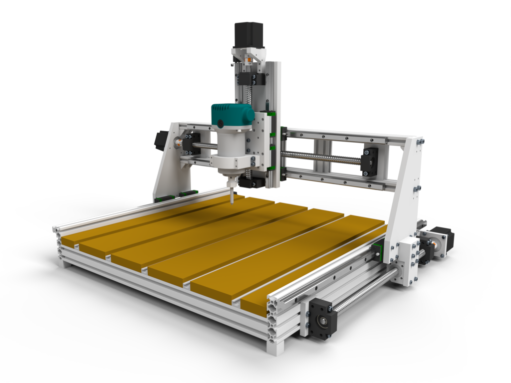
You can get the 3D model of this DIY CNC Machine, as well as the STL files for 3D Printing from Cults3D.
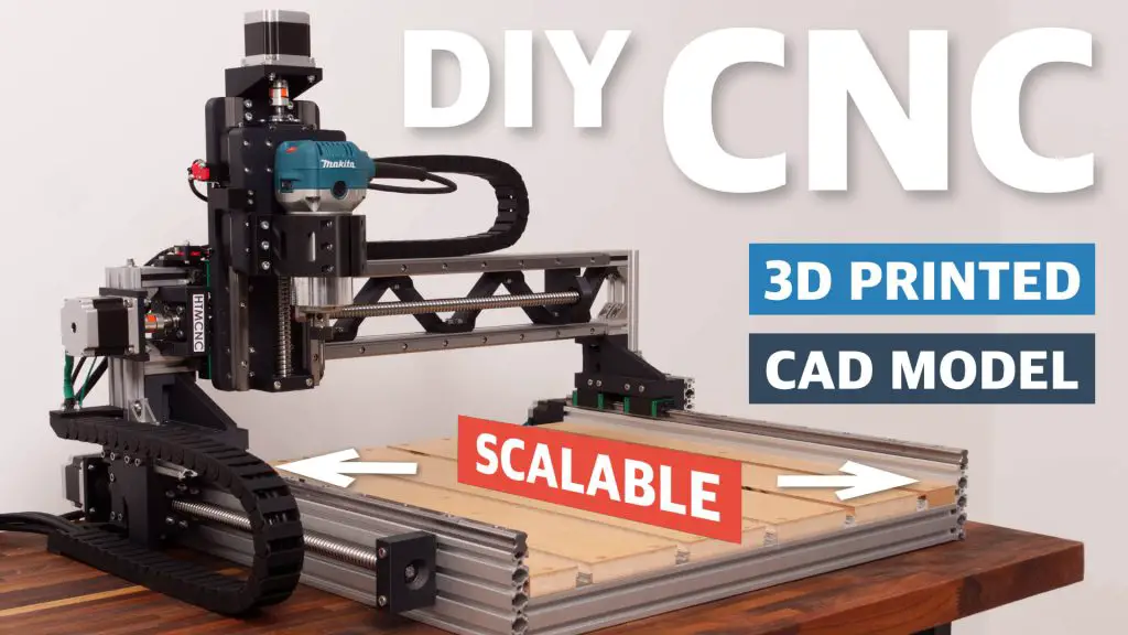
Here’s the original HTMCNC 3D printed CNC Router:
Bill of Materials
Below is the complete list of components needed for this DIY CNC build.
The given dimensions are for the exact same size as the CNC I demonstrated building with 450x350mm work area.
You can also check out my e-store HT-Mechatronics where you can find the following components as a kit, so you can easily order everything you need for this CNC build.
★ RECOMMENDED PROJECT KIT
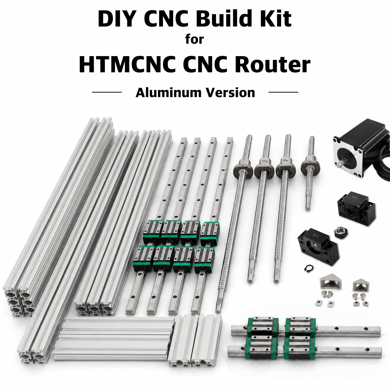
Complete DIY Project Kit
Everything needed to build this project, selected to match the parts used in the tutorial.
- Parts selected to match this project
- No need to source components individually
- Mechanical and electronic components included
- Supports future How To Mechatronics projects
Already have some parts? Buy individual components below.
Aluminum plates and bars Kit for HTMCNC Aluminum DIY CNC Router
| Component | Quantity | Purchase Links |
|---|---|---|
| Aluminum Extrusion 2080 – 600mm (Y-axis, Custom Length) | 2 | Amazon | AliExpress |
| Aluminum Extrusion 2040 – 600mm (X-axis Base, Custom Length) | 3 | Amazon | AliExpress |
| Aluminum Extrusion 2040 – 700mm (X-axis Gantry, Custom Length) | 2 | Amazon | AliExpress |
| Aluminum Extrusion 2040 – 200mm | 2 | Amazon | AliExpress |
| Aluminum Extrusion 2040 – 100mm | 2 | Amazon | AliExpress |
| Linear Rail HGR15 – 600mm (Y-axis, Custom Length) & (X-axis, Custom Length) | 4 | Amazon | AliExpress |
| Linear Rail HGR15 – 300mm (Z-axis) | 2 | Amazon | AliExpress |
| Ball Screw SFU1605 – 500mm (Y-axis, Custom Length) | 2 | Amazon | AliExpress |
| Ball Screw SFU1605 – 600mm (X-axis, Custom Length) | 1 | Amazon | AliExpress |
| Ball Screw SFU1605 – 300mm (Z-axis) | 1 | Amazon | AliExpress |
| Shaft Coupler 8mm to 10mm | 4 | Amazon |AliExpress |
| Angular Contact Bearings – 7001 P5-DB A-Pair | (4 pairs) | Amazon | AliExpress |
| M12x1mm Locknut | 4 | Amazon | AliExpress |
| Radial Ball Bearing – 6000 – 2RS | 4 | Amazon | AliExpress |
| Corner Bracket 28x20x28mm (with suitable T-slot nuts and M5 Bolts) | 20 | Amazon | AliExpress |
| Corner Bracket 20x20x20mm (with suitable T-slot nuts and M5 Bolts) | 10 | Amazon | AliExpress |
| M5 Sliding T-nut | 100 | Amazon | AliExpress |
| M5 Hammer Head T-nut | 100 | Amazon | AliExpress |
| M4 Sliding T-nut | 50 | Amazon | AliExpress |
| M4 Hammer Head T-nut | 50 | Amazon | AliExpress |
| Stepper Motor NEMA23 | 4 | Amazon | AliExpress |
| HEX Socket Head Bolts M4x12mm – 16 M4x14mm – 50 M4x16mm – 16 M4x20mm – 16 M5x12mm – 8 M5x16mm – 50 M5x20mm – 28 M5x35mm – 8 M6x20mm – 8 M6x25mm – 8 M6x35mm – 20 M6x40mm – 24 | / | Amazon | AliExpress |
Disclosure: HT-Mechatronics is my own store. Amazon and AliExpress links are affiliate links, which means I may earn a commission from qualifying purchases at no additional cost to you.
SKIP THE SOURCING
Want everything in one order?
Get the components selected specifically for this project.
Assembly
You can follow the following video for a complete step-by-step guide on how to build this DIY 3D Printed CNC machine.
Rigidity – 3D Printed vs Aluminum DIY CNC
And now the moment of truth, let’s check out the rigidity of this all-aluminum DIY CNC machine. Will it be better than the 3D printed version?
So, using a dial indicator I will measure how much the machine will deflect under a load.
First I’m testing the X-axis rigidity. At the force of 50N, the deflection was 0.1mm, and at a force of 70N, 0.14mm.
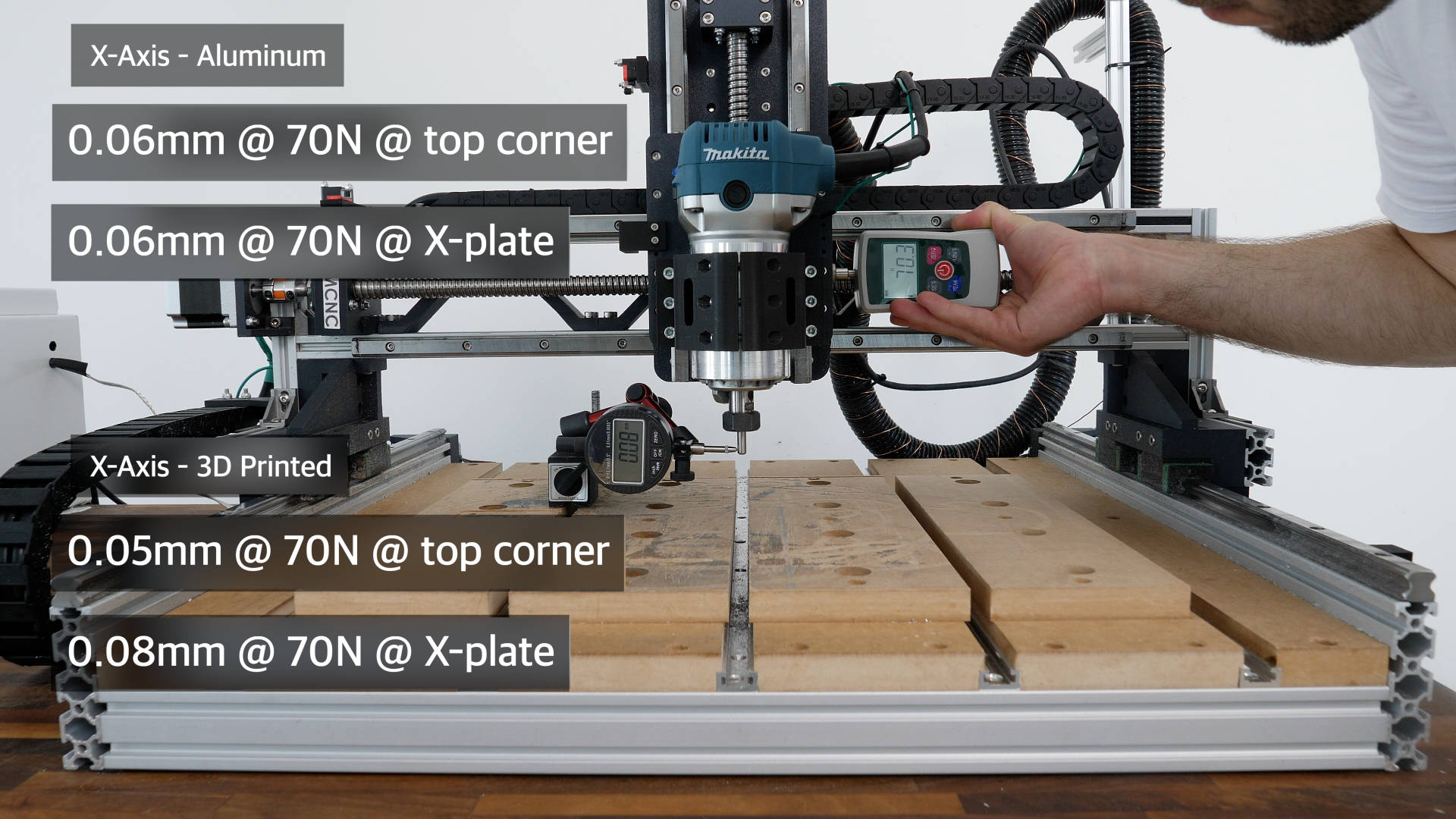
Compared to the 3D printed version, which had around 0.16mm deflection at a force of 50N, and 0.22mm deflection at a force of 70N, that’s quite better rigidity of around 35%.
The deflection in the Y-axis was the same as the X-axis for both CNC machines.
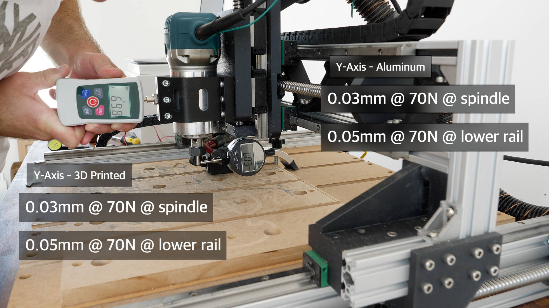
As for the Z-axis there was even more significant difference between the all-aluminum and the 3D printed version.
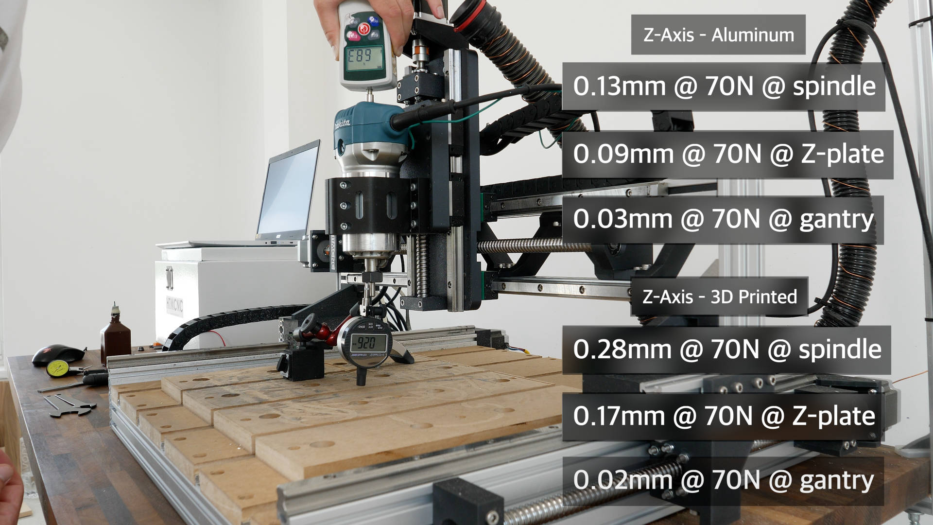
At a force of 70N, the deflection of the all-aluminum CNC in the Z-axis was around 0.17mm, and on the 3D printed version 0.39mm. That’s more then 100% difference in rigidity. Though, that was expect as the 3D printed X-plate was only 14mm tick, while this aluminum plate is 15mm tick, so there is no question that he later will be much more rigid.
So, overall, the all-aluminum version showed like 35% improvement in rigidity in the X and Y directions, and 100% improvement in the Z direction. However, I got some interesting results when I was testing the deflection at the end mill, while applying force at different locations.
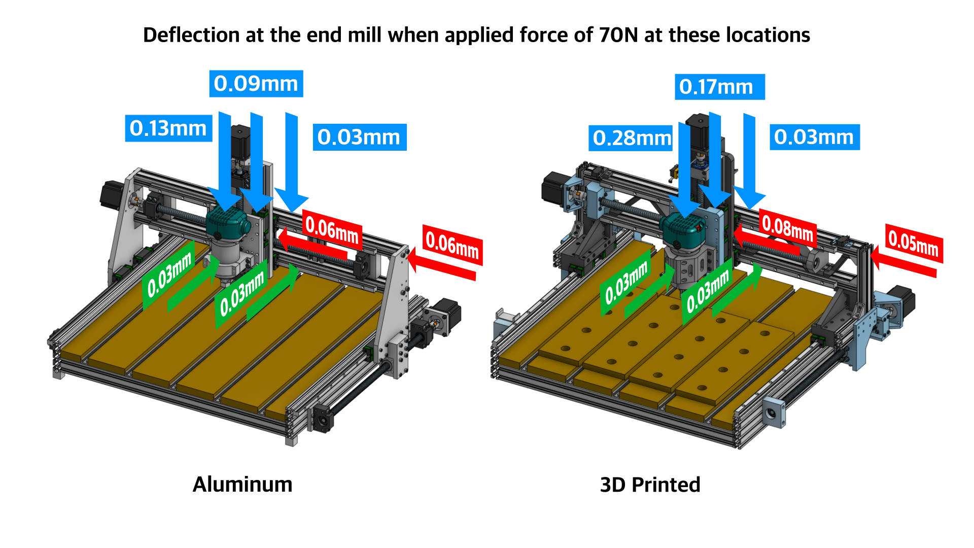
Testing the X-axis, when applying a force of 70N at the gantry top corner, the deflection at the end mill was 0.06mm, and the same results when applying the same force at the X-plate. That was a bit of surprising for me, as I got almost the same results with the 3D printed CNC, 0.06mm when pushing the gantry top corner, and 0.08mm when pushing at the X-plate. So that’s much less difference between the two versions.
The results ware similar to for the Y-axis as well. A deflection of 0.03mm when pushing at the middle of the router or the gantry, and 0.05mm, when pushing at the lower rail of the gantry. On the 3D printed version, the results were almost the same, 0.04mm and 0.05mm at those locations.
As for the Z-axis, when pushing on top of the router, the all-aluminum CNC end mill deflected 0.13mm, 0.09 when pushing the Z-plate, and 0.03mm when pushing the top of the gantry.
On the 3D printed version, the results were 0.28mm, 0.17mm and 0.02mm respectively.
So from these results, we can conclude the following. The gantry structure and rigidity of the two CNC machines is almost the same. Although 3D printed, those big corner brackets and the truss elements makes gantry of the 3D printed version as rigid as the aluminum version.
The difference starts to occur on the X plate, where the 3D printed version lose some rigidity compared to the aluminum version, especially in the Z-axis. Though, biggest difference in the overall rigidity makes the router mount.
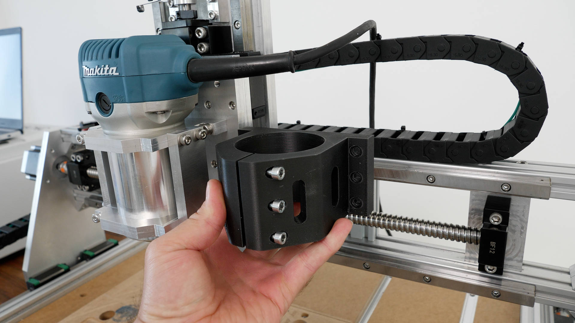
I mean, if we compare them side by side, it makes sense, as the 3D printed version has only 10mm tick wall on the sides, and 14mm tick flange for connecting it to the Z plate. We can definitely make it much sturdier by increasing those walls thicknesses. It’s a pity that I disassembled the 3D printed CNC machine already, so I cannot test it with a stronger mount at this moment, but I will do that in my next video where I plan to make a large version of it, including some improvements of the 3D printed parts, so stay tuned.
Accuracy
Anyhow, the relatively high rigidity that we got on this new all-aluminum DIY CNC machine, enable us to machine aluminum parts with accuracy of 0.02mm in the X and Y directions.
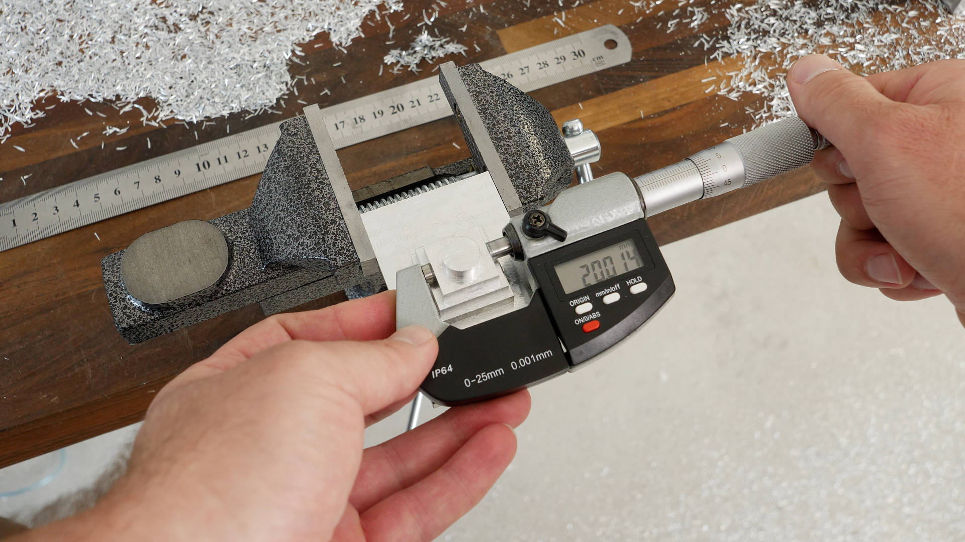
I did several test parts and these results were confirmed multiple times.
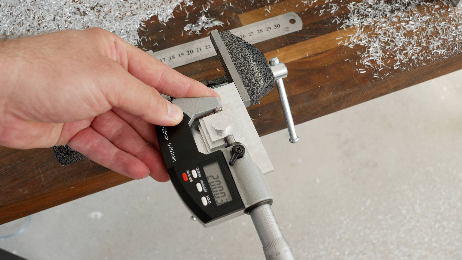
Though, like I said, I got the 0.02mm accuracy in the X and Y direction, but when checking the accuracy diagonally, on a circle for example or a hexagon, the accuracy was about 0.04mm or 0.05mm.
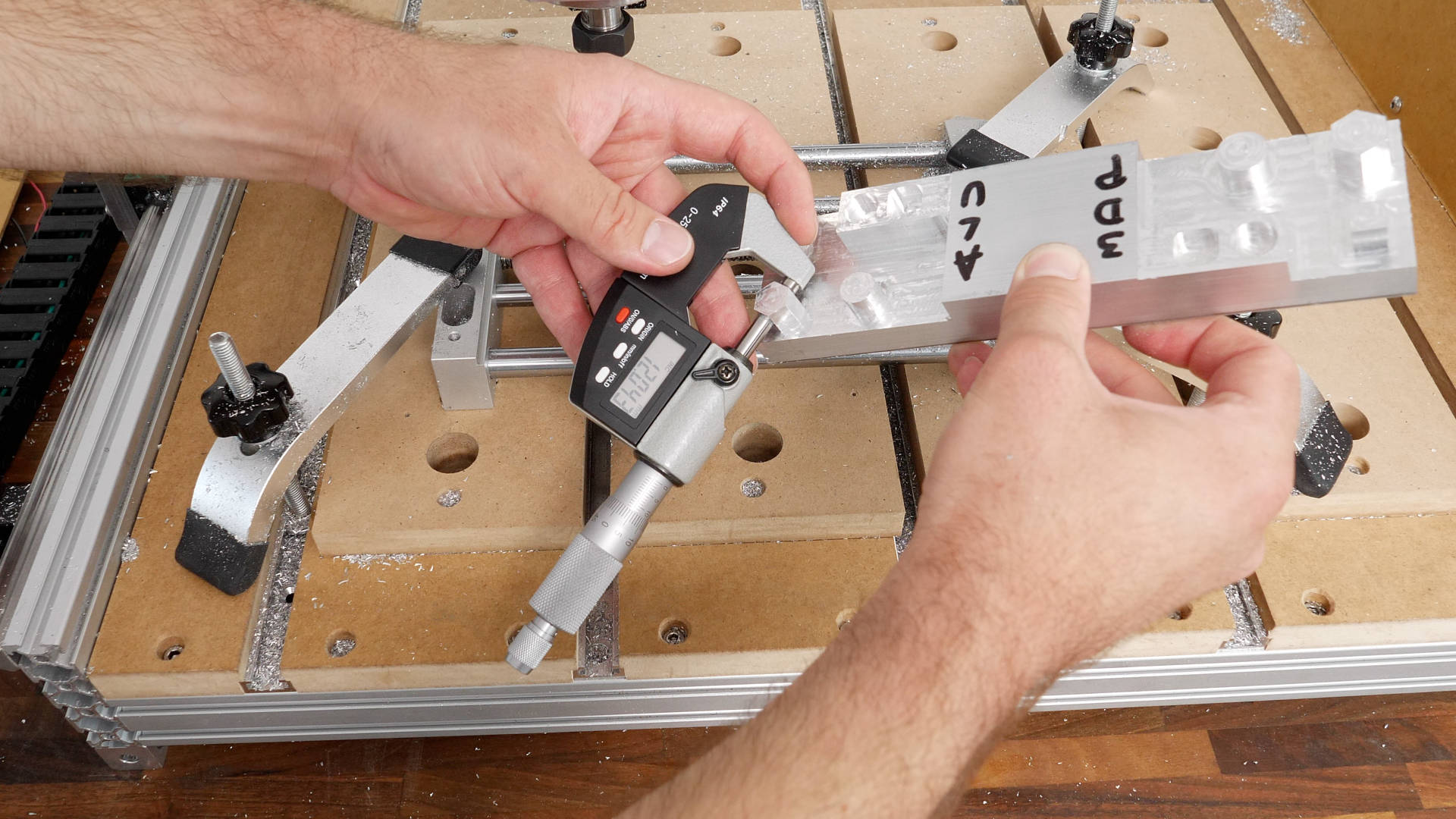
That’s so because when cutting diagonal, both the X and the Y axes are engaged, and their error is combined, resulting in higher value.
Cutting Steel Accuracy with DIY CNC
I also tried cutting steel which is much harder and complicated to machine compared to aluminum.
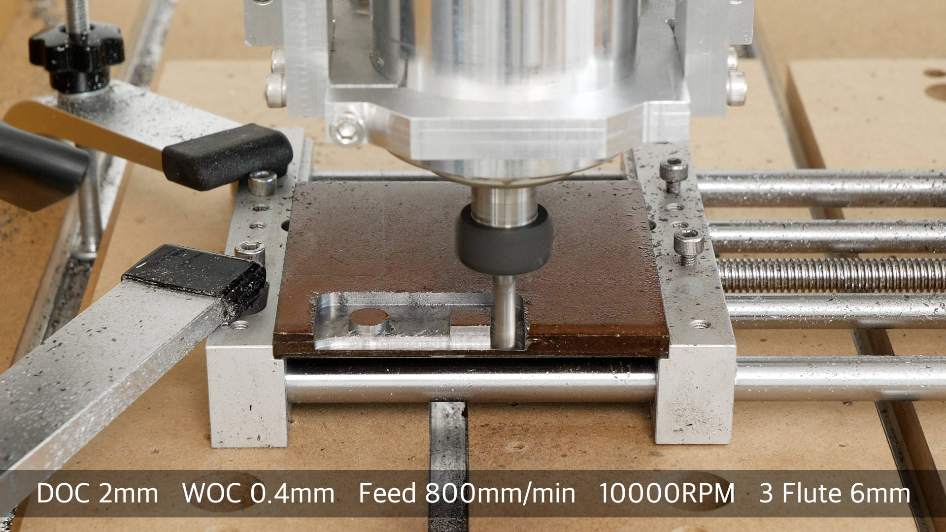
For the roughing I used 2mm DOC and 0.4mm WOC at 800mm/min feed rate and 10K RPM. For getting the machined parts as closes as possible to the actual dimensions, I used an offset of 0.05mm when doing the finishing profile pass. In that way, I got the parts within 0.03mm of the actually dimension.
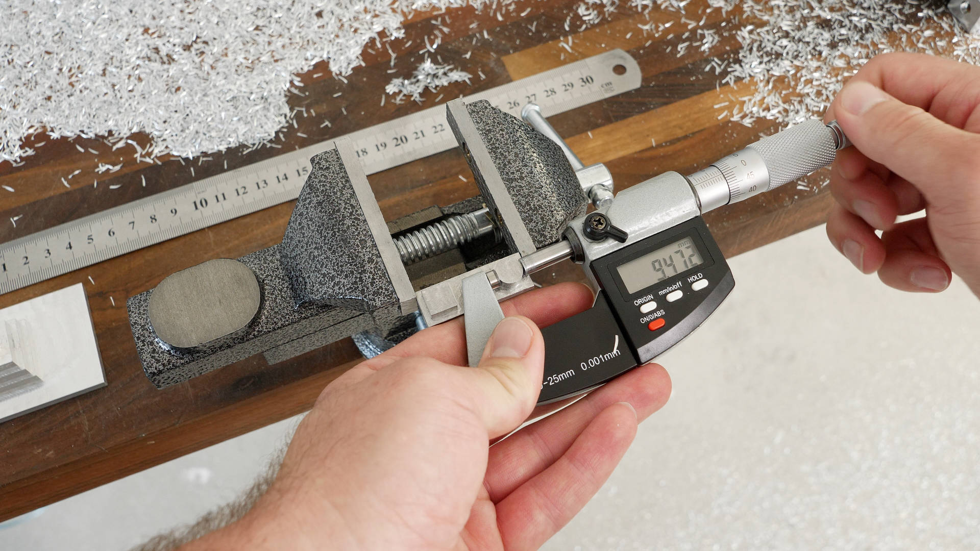
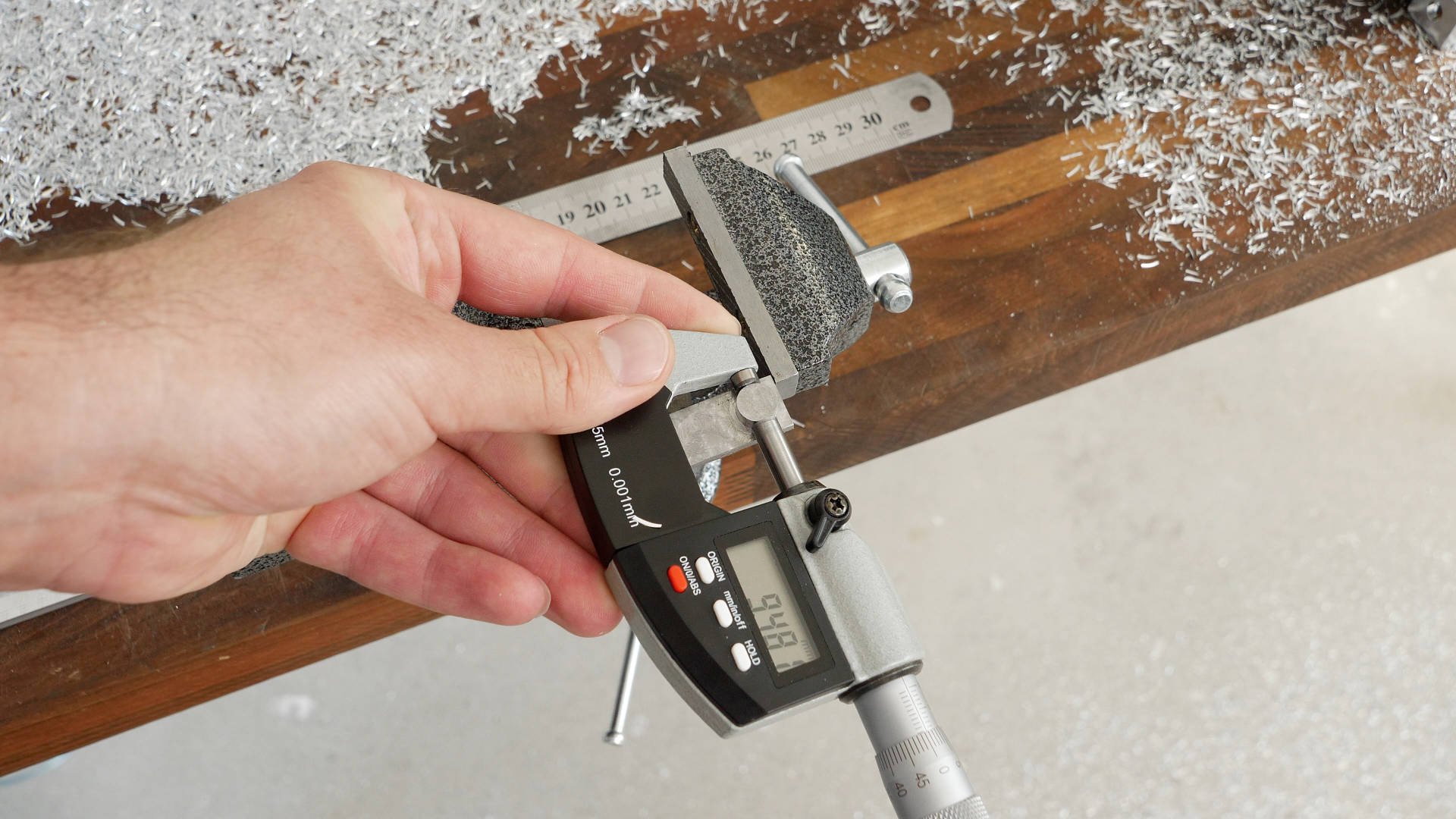
I used that offset value because when I was checking the router end mill accuracy, I could have noticed around 0.03mm or 0.04 misalignment. And that was near the collet of the router, and it might be greater that the tip of the end mill.
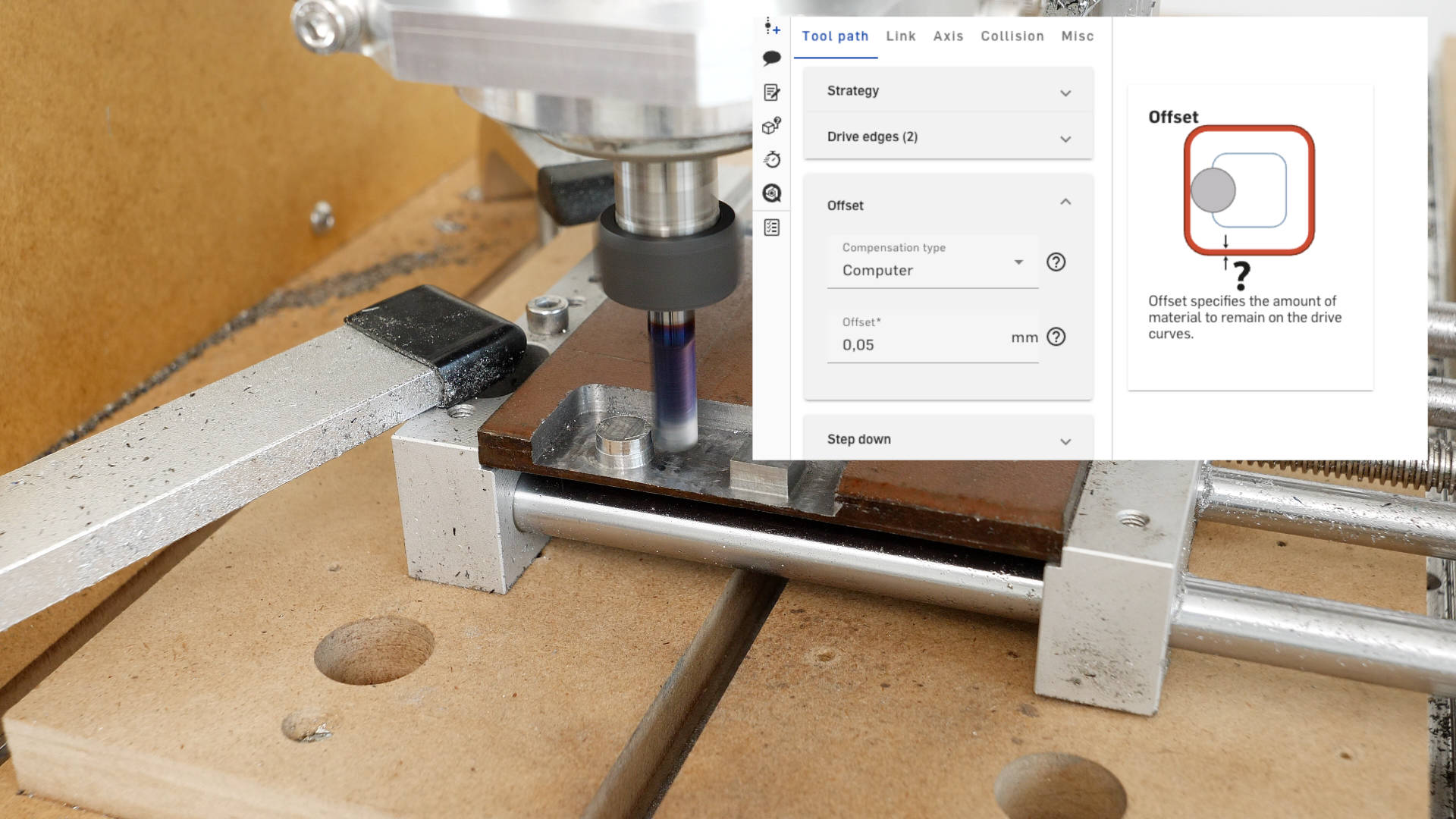
Sometimes I was getting just 0.02mm, and on other collets and end mills even 0.08mm misalignment. That tell us us that the router or the spindle and its collet make a huge difference for the accuracy of the machined parts. If we try to get accurate results we should always check the end mill misalignment using a dial indicator and compensate for that in software by adjusting the offset when cutting the particular shape.
This is definitely a week spot for the Makita router, which is not intended for precision works. I actually got myself a real VFD 2.2kW spindle with high precision ER20 collets and I’m looking forward to test it on this CNC machine. I didn’t have the time to include it in this video, so stay tuned for my next videos.
Verdict – 3D Printed vs All-Aluminum DIY CNC
What’s my final verdict on these two CNC machines, which one is better, the 3D printed one or the all-aluminum DIY CNC machine?
Well, in terms of cost, the 3D printed version wins, as it’s a bit cheaper to build. In terms of the assembly process, the 3D printed one also wins as it’s a bit easier to assemble, without any need of manually drilling holes or making threads to them.
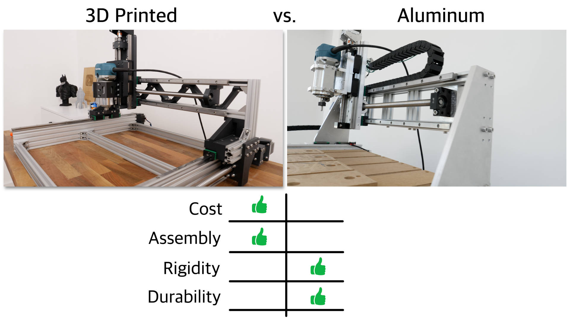
However, in terms of rigidity and durability the aluminum CNC definitely wins. It’s not like it’s extremely more rigid, but still like 10 to 20%. We saw in the tests that the router mount made the biggest difference so an improved version of it, could close the gap between them.
Overall, the biggest difference between the 3D printed and the Aluminum CNC machine would be the durability. We know that the aluminum one will last for years, but not sure about the 3D printed version. I don’t know how long the 3D printed parts will hold, without creeping or deforming or degrading. So if I have to say which one is better, the Aluminum one is, but the 3D printed one is definitely good option as well.
Please let me know your thoughts in the comments section below. Which one will you go for?
And how about a hybrid approach? Would you like to see a new design combining aluminum parts at crucial and 3D printed parts at not so crucial parts? That might be a good idea, so stay tuned!

The holes for the bearing blocks are in a square pattern but my blocks have more of a rectangle pattern? They were advertised as hgr15 like in the bom, is thier alternative files for me to print or do I need to figure out how to modify them?
Hey, I’m sorry I didn’t quite understand your question.
Please use the forum to ask question there where you can also include screenshots for better understanding.
Here’s a link to the forum: https://community.howtomechatronics.com/
My apologies, I had the wrong part that I was going to fasten to the rail and I returned to your video to reference and realized my mistake. Thank you for the help.
can not view the 3D model on Onshape.
Hey, I fixed the link, check it out now.
Great work Dejan