In this tutorial I will show you how I build a CNC controller based on Arduino and GRBL, for the DIY 3D Printed CNC Machine that I showed you how I built in my previous video.
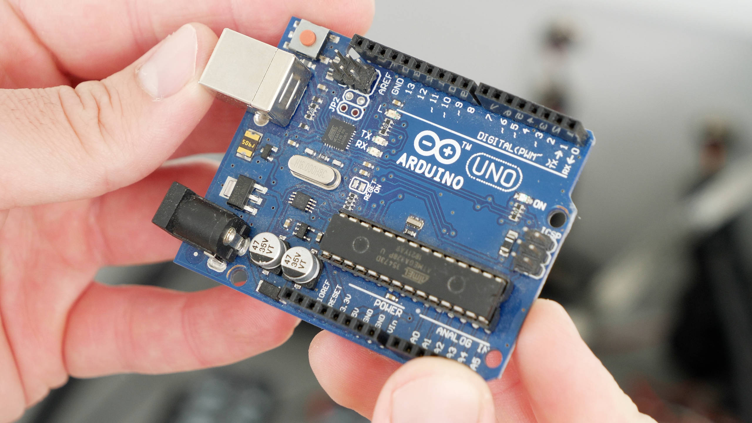
Isn’t it fascinating that this 8-bit, inexpensive and probably the most popular electronics prototyping board, the Arduino UNO based on the ATmega328P microcontroller, is capable of being a CNC motion controller and we are able to produce high quality stuff with it.
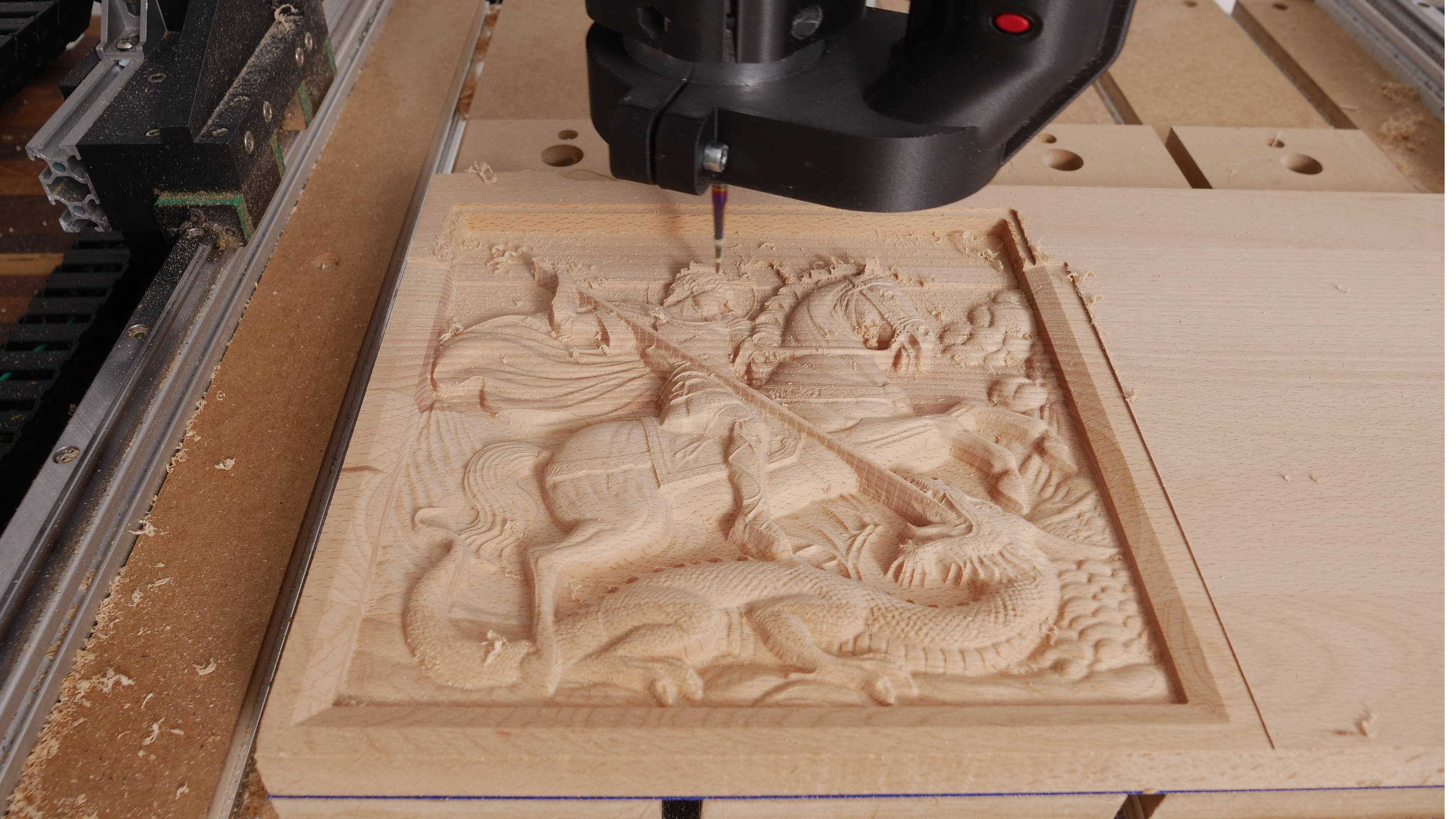
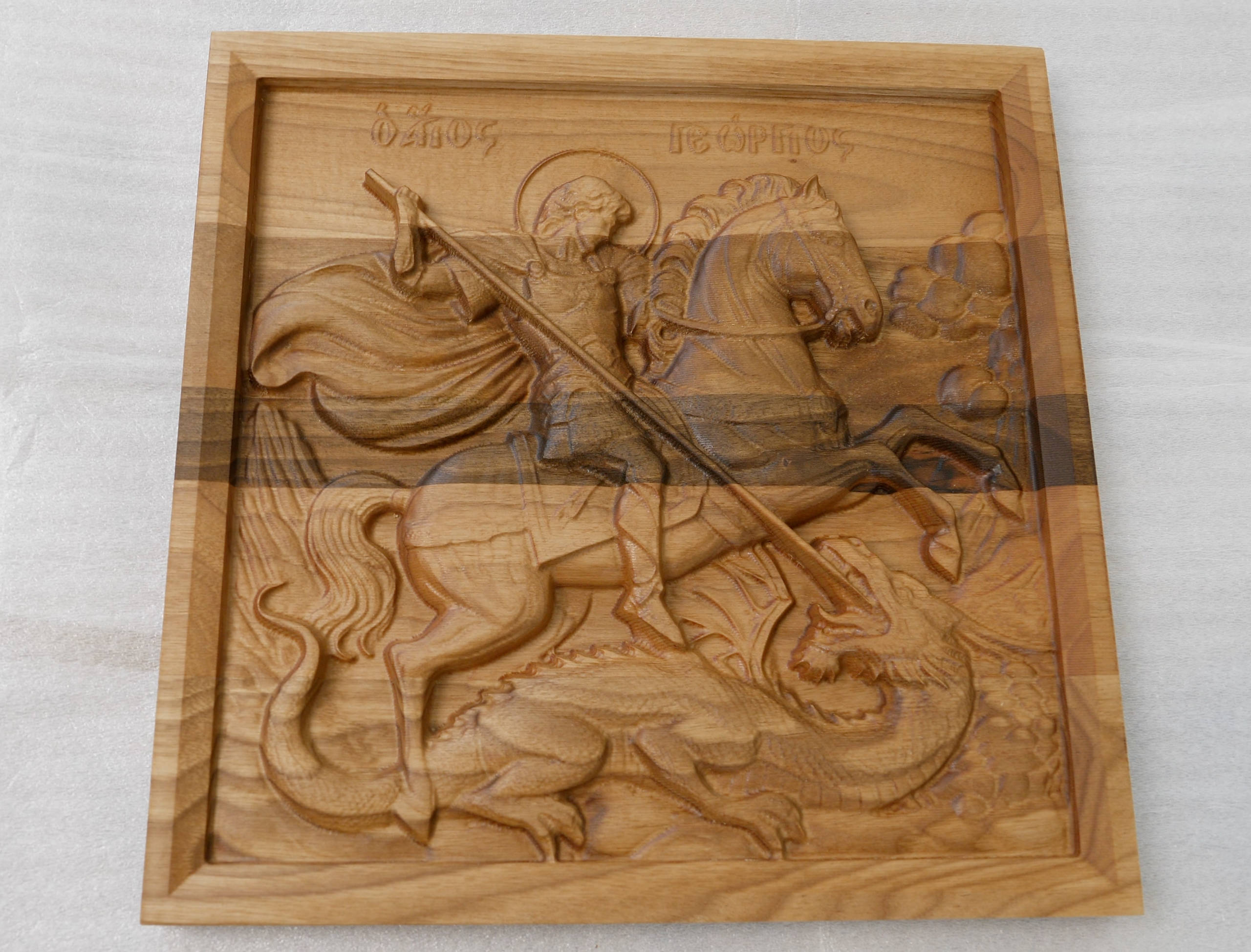
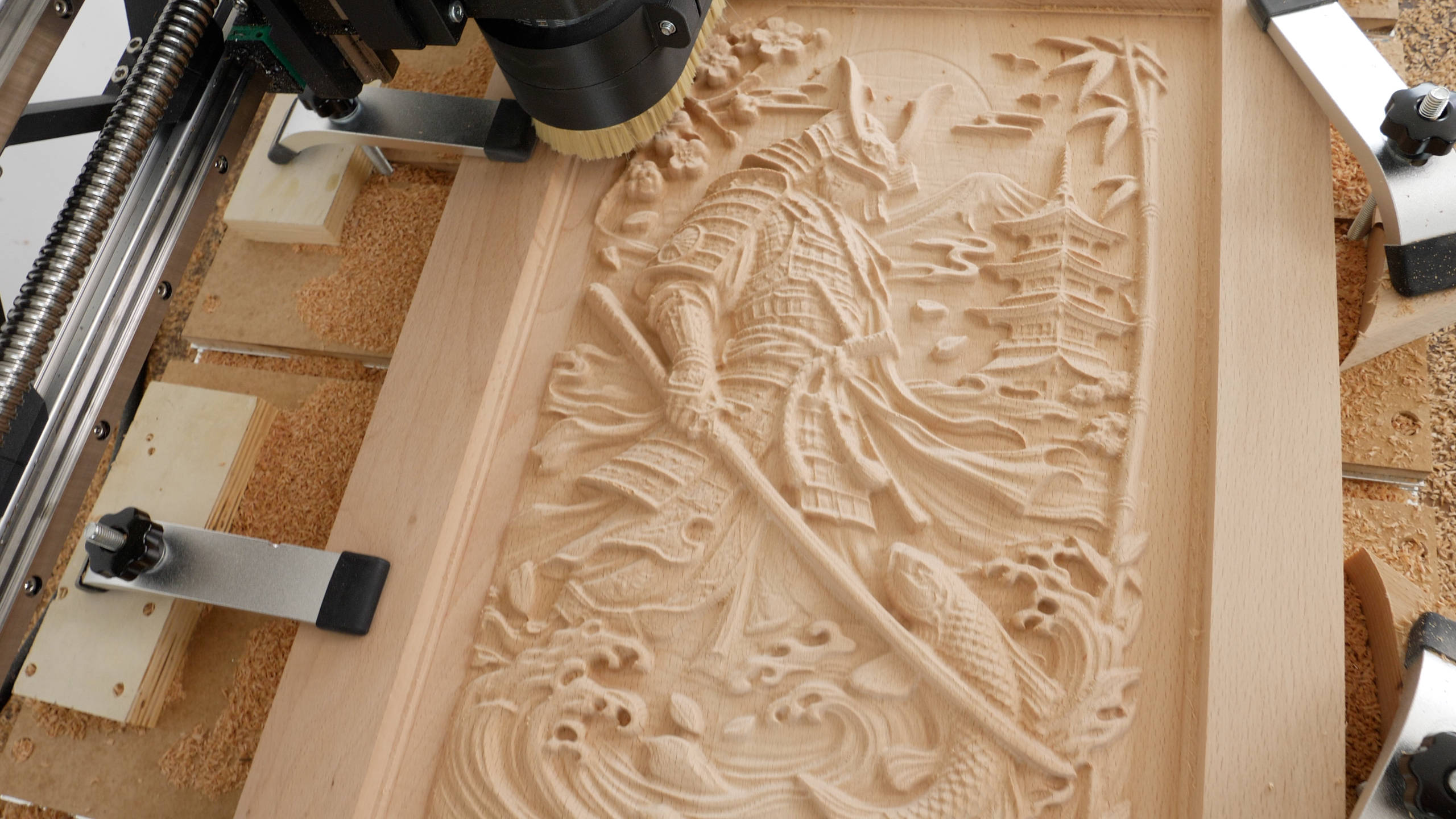
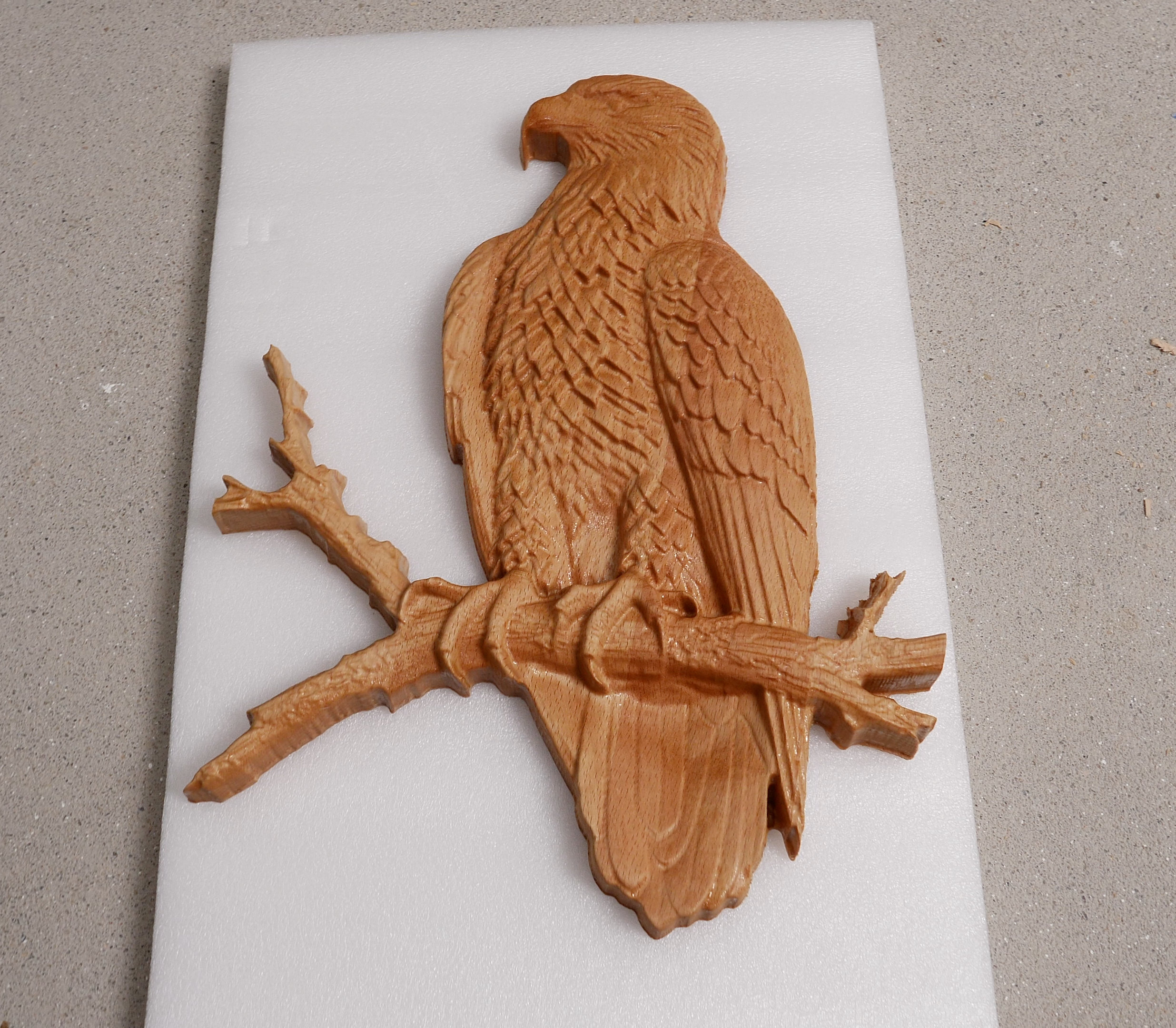
Just take a look at the projects that I made with it. We can get really fine details and probably make anything we can think of with it.
I mean, to me that’s really fascinating, but does it sound too good to be true? Stick around to find out, as I will walk you through the entire process of building this Arduino and GRBL CNC controller, show you all the problems I encountered in order to get it working properly, and show you why and how I designed a custom Arduino UNO shield for this CNC build.
In this video I will also cover how I did the wiring on my DIY 3D Printed CNC Machine from the previous video, as well as how to setup GRBL and make your first cuts with your CNC machine using the Universal G-code Sender.
Arduino and GRBL Setup
All right, so let’s start with the CNC motion controller. There are so many options for a CNC motion controller to the point that is really overwhelming especially for beginners. I chose to use the Arduino and GRBL combo because it’s a popular choice among CNC beginners and it’s one of the cheapest options for a CNC controller.
Anyhow, let’s take a look at this diagram first, so we can better understand how our CNC machine will work in combinations with this Arduino and GRBL CNC Controller.
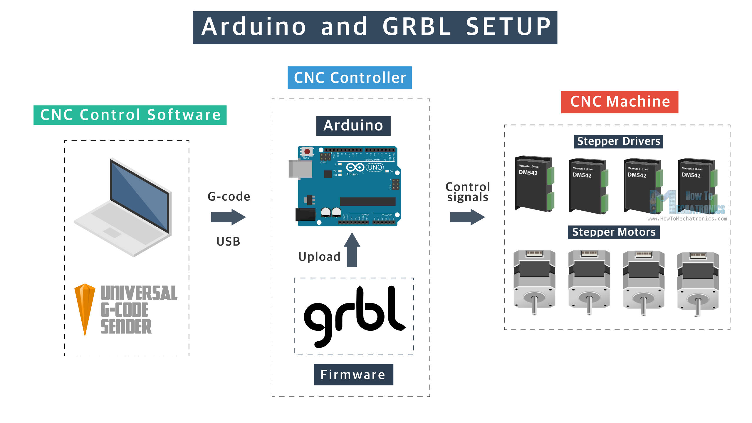
So, the Arduino board, or the ATmega328P is the microcontroller on which we need to install the open-source GRBL motion control firmware. Together they make the CNC motion controller which job is to translate the digital instructions or the G-code into electrical signals that will drive the motors, and eventually the CNC machine.
We also need a CNC control software on our computer, that will send the G-code to the Arduino via USB connection. There are many options here as well, but I will use the popular Universal G-code Sender which is also open-source.
A CAD/CAM software is also needed to create 2D or 3D digital models and generate instructions or G-code for the model.
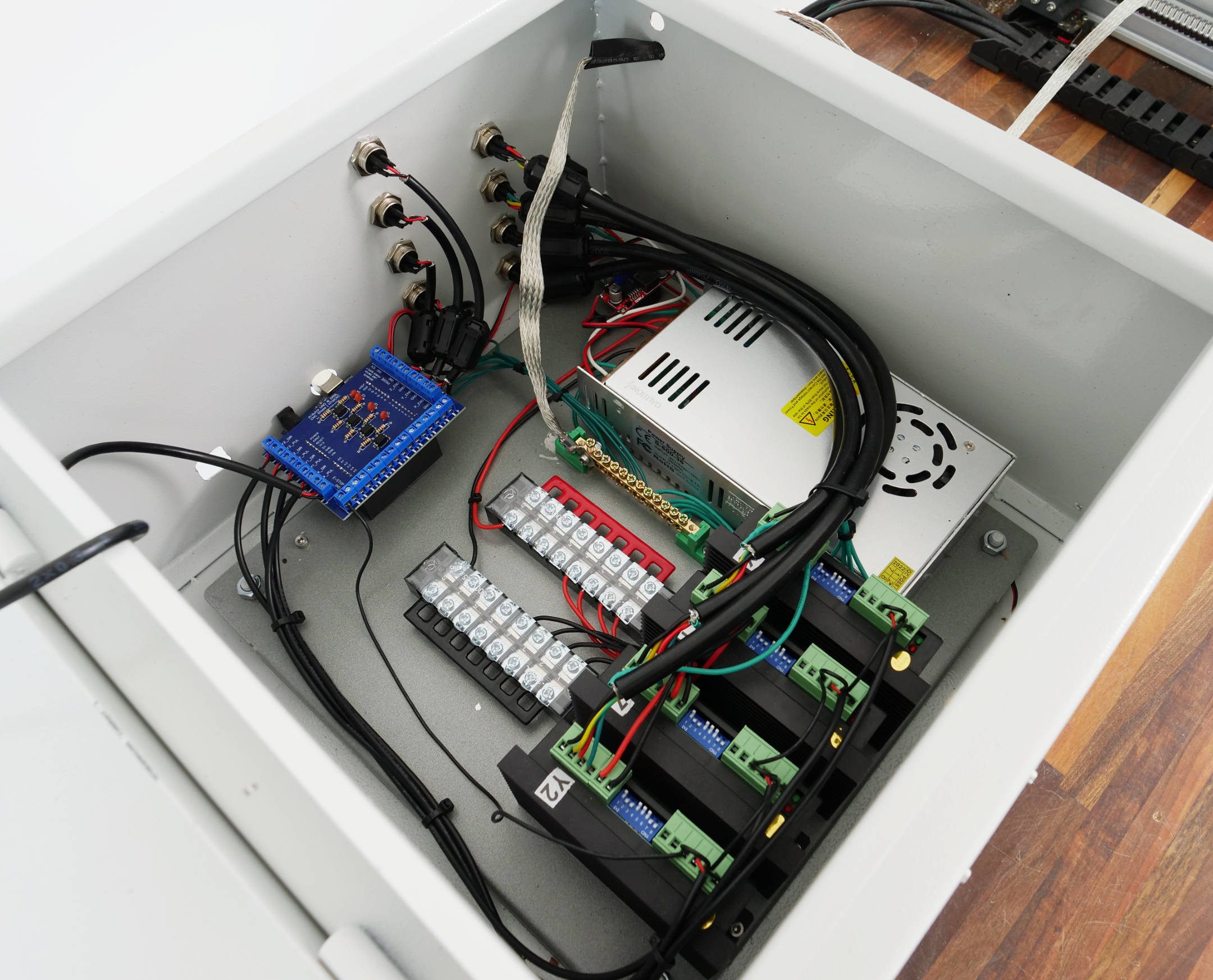
DIY CNC Control Box Circuit Diagram – Wiring
Of course, the CNC motion controller itself cannot do much if it’s not companioned with some other electronics components, like a power supply, stepper drivers, limit switches etc.
Here’s the circuit diagram or how everything needs to be wired for our Arduino and GRBL CNC motion controller to work with our CNC Machine.
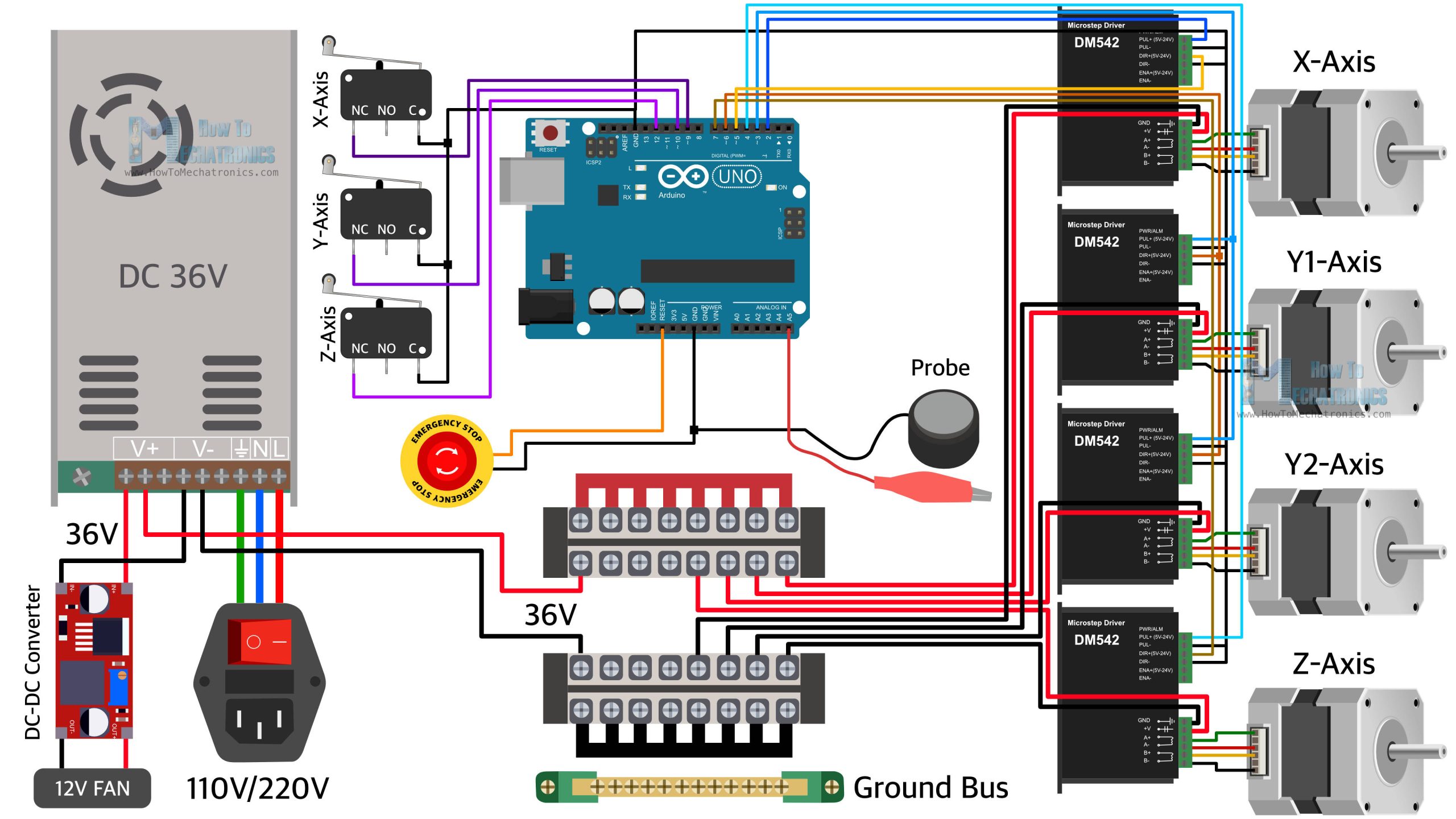
So we have the Arduino UNO as the brains of our CNC machine, which controls the four NEMA23 steppers motors through the four DM542 stepper drivers. This is a 3-axis CNC machine, but we use two motors for the Y-axis, so therefore we need 4 motors total. For powering these steppers motors and drivers, we can use a power supply from 24V to 48V. A higher voltage allows for higher torque at higher speeds. The power supply needs to have enough power to handle the four motors power draw. I chose a 36V power supply, rated at 16.7A or that’s 600W power supply. That’s enough power for these four NEMA23 steppers motors, which we will later set to draw around 1.5A to 2A of current each.
For powering the control box cooling fan we need 12V, but instead of using another 12V power supply I decided to us a DC-DC converter to step down the 36V to 12V. I also used these 12V for powering the optocouplers that we will use for electrically isolating the limit switches from the microcontroller. The optocouplers help reduce the problems with false alarm triggers that occur due to EMI, or electromagnetic interference. This Arduino and GRBL CNC motion controller is particularly prone to EMI issues and false alarm triggers, but more on that later in the video where I will explain how I dealt with them.
We also need an E-stop button, and a probe, as well as some terminal blocks for better managing the wiring.
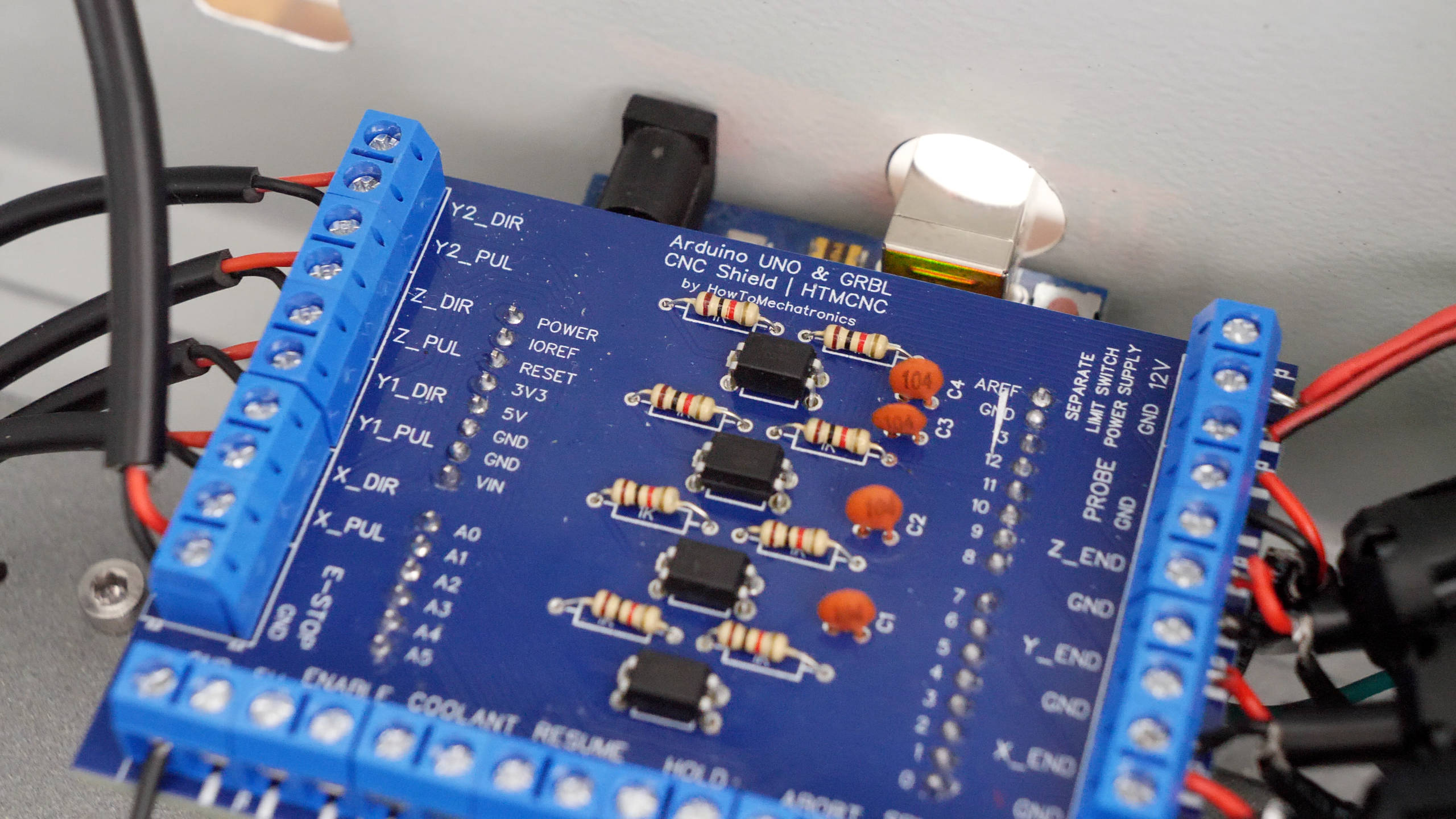
Custom Arduino UNO Shield PCB
Speaking of managing the wiring, I designed a custom PCB or an Arduino UNO Shield for easily connecting everything.
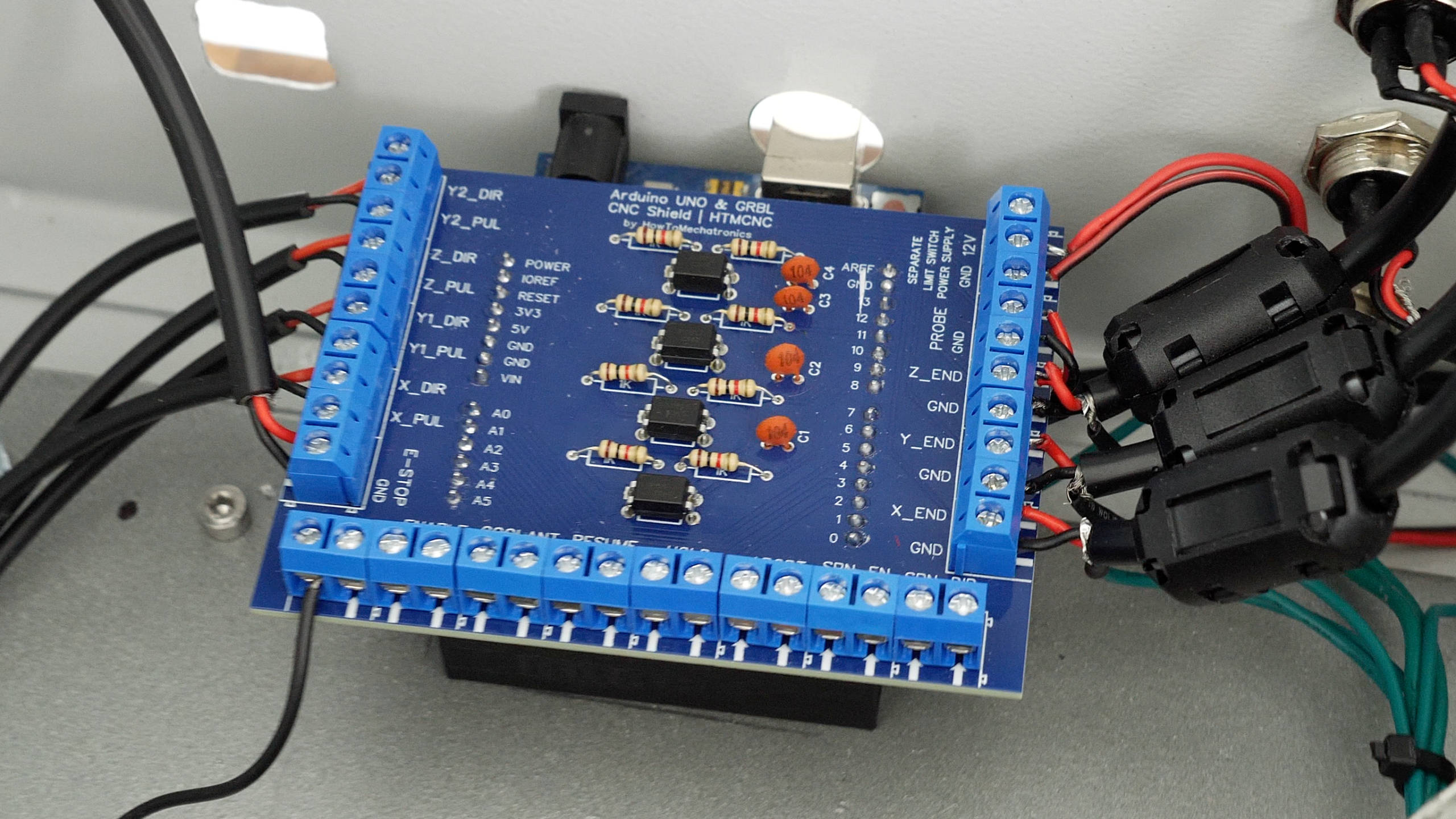
The Arduino UNO uses standard 2.54mm female pin headers for the I/O pins, and they are not really good for directly connecting our CNC machine components like the limit switches and the drivers to them.
I tried using them in that way in my initial control box that I made, by soldering pin headers to the wires of the limit switches and the drivers, and also using the Arduino CNC Shield, but I found that they don’t make good connection and can get loose, so they are not good option especially in conditions like this.
In this custom Arduino UNO shield that I designed, I’m using 5mm screw terminal blocks that provide more secure connections for the I/O pins. In addition to that, I also integrated the optocouplers on the PCB, for electrically isolating the limit switches from the microcontroller.
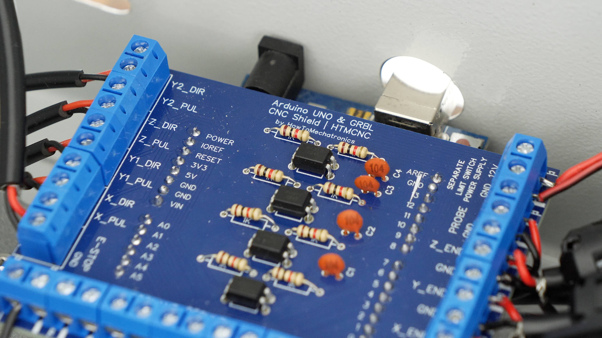
I used the popular PC817 optocouplers for that purpose, which need two resistors to work properly. I chose the resistors value to work with the 12V at the input, because as I mentioned we will use the 12V from the DC-DC convertor for that purpose.
You can find and download the Gerber file for this PCB, from PCBWay project sharing community through which you can also directly order the PCB. You can order just the PCB and solder the components on your own, or you can also order the PCB assembled.
Bill of Materials
Below is the complete list of components needed for this DIY CNC build.
| Component | Quantity | Purchase Links |
|---|---|---|
| Metal Enclosure – 400x400mm + | 1 | Amazon |
| DM542 Stepper Driver | 4 | Amazon | AliExpress |
| Power Supply 36V 600W | 1 | Amazon | AliExpress |
| Ground Bus Bar | 1 | Amazon | AliExpress |
| Terminal blocks | 2 | Amazon | AliExpress |
| DC-DC Converter 3A | 1 | Amazon | AliExpress |
| Cooling Fan 12V | 1 | Amazon | AliExpress |
| Double-shielded cable – 4 wires | 10-15m | Amazon | AliExpress |
| Double-shielded cable – 2 wires | 10-15m | Amazon | AliExpress |
| Wires | 10m | Amazon | AliExpress |
| GX16 connector – 5 pin Male + Female | 5 | Amazon | AliExpress |
| GX16 connector – 3 pin Male + Female | 5 | Amazon | AliExpress |
| AC Socket with Switch and Fuse | 1 | Amazon | AliExpress |
| Trim router – Makita | 1 | Amazon | AliExpress |
| Various M3 and M4 bolts and nuts (list to be updated) | Amazon | AliExpress |
Disclosure: These are affiliate links. As an Amazon Associate I earn from qualifying purchases.
Assembling the CNC Control Box
You can watch the following video for a complete step-by-step guide on how to build this Arduino and GRBL CNC control box.
Wrap-up
Now let’s wrap up this video and let me tell you my opinion about this Arduino and GRBL CNC controller that I built.
As you saw, the biggest problem with this CNC controller is the instability of the system caused by EMI. I think I tried to implement every possible solution to eliminate the false alarm triggers related to EMI but I didn’t manage to do it 100%. Although I implemented all best practices like using double-shielded cables, electrically isolating the limit switches from the microcontroller with optocouplers, using ferrite cores, using a start ground connection and grounding the CNC chassis and the dust hose, I still couldn’t get this Arduino and GRBL CNC controller 100% stable.
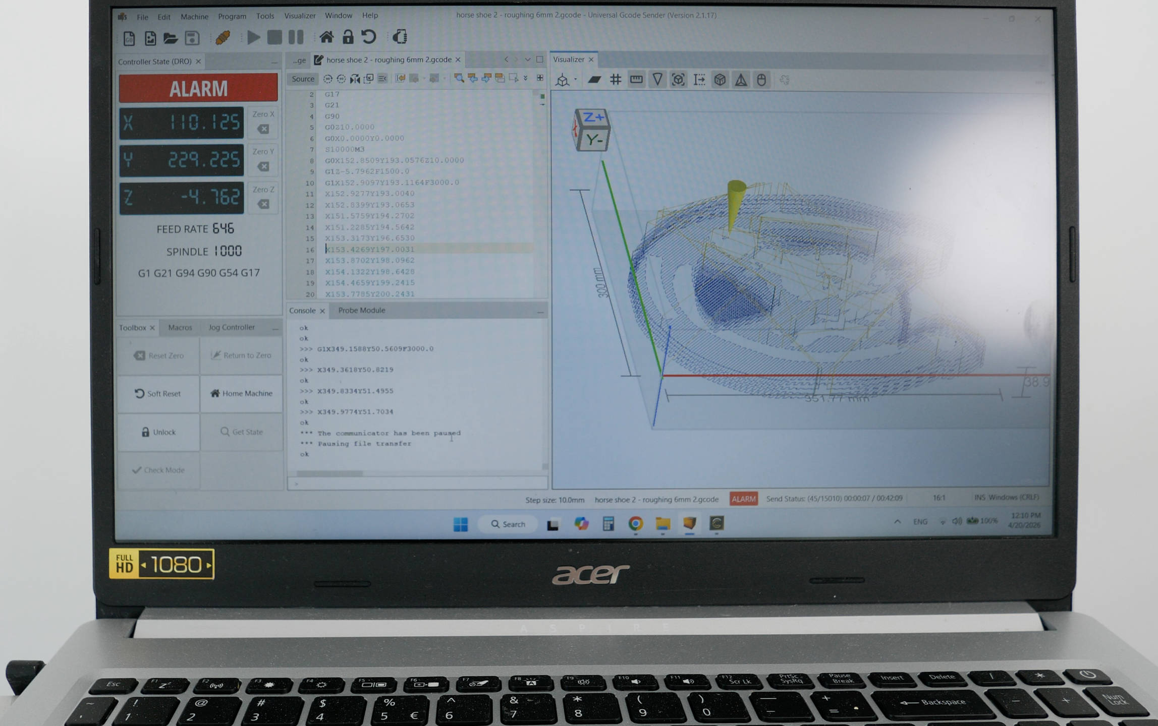
I guess there is always room for improvement, I might be missing something, but according to Vince from the YouTube channel Corvetteguy50 there is actually no way we can get this system 100% stable because of the USB connection itself. He states in many of his videos that this has been confirmed by a lead engineer at CNC Drive responsible for making the UC100 USB controller.
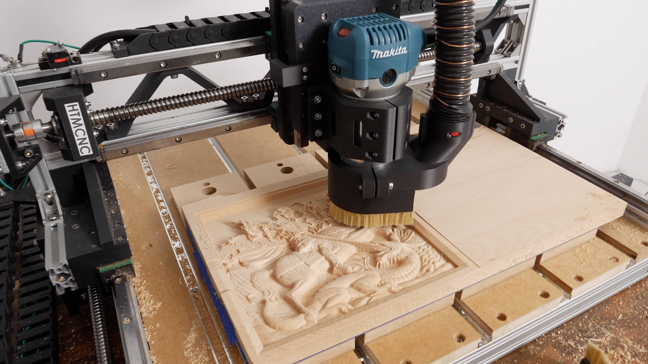
Nevertheless, despite the fact that we cannot get this Arduino and GRBL CNC controller 100% stable, I think it’s still an OK option especially if you are on a budget. I mean, I can confidently make any project with it, like for example, I made this 5 hours 3D relief without any problems or false triggers, and several other projects.
With all the best practices that I implemented for reducing the EMI issues, this system works fairly good if we do not overload it.
That’s right, now I was only getting false alarm triggers if I pushed the machine really hard, like 3000 mm/min federate, or 8mm depth of cut in wood or similar. When using more moderate settings like 2000 mm/min federate and 4mm or 6mm depth of cut with 6mm end mill, I didn’t have problems with the false alarms.
The trim router I am using here makes greater EMI when overloaded causing the USB controller to trigger a false alarm. I cannot tell for sure but maybe a dedicated spindle with VFD would work better and more stable.
Other than that, we could go with a CNC controller that uses an Ethernet communication which is more stable than USB. I will try some Ethernet CNC controllers in my next videos, so stay tuned for the results.
I will say it again, if you are on a budged, this Arduino and GRBL CNC controller is ok option, as it would cost you only like $10 to $15 for the microcontroller and another $30 to $50 for the custom Arduino CNC Shield with the optocouplers, so total around $40 to $60.
On the other hand, an Ethernet microcontroller would be minimum $100, but on top of that you would require a licensed controller like Mach 3 or 4 or some other options which can cost around $200 also. So that’s a minimum of $300 for such a controller.
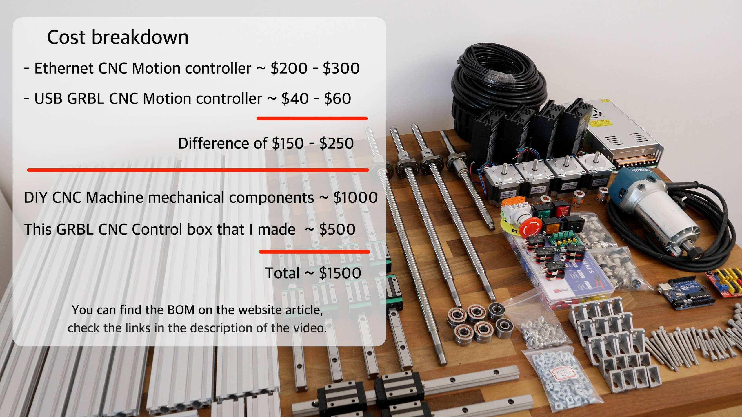
That’s a significant difference, not question about that, but if you are already spending like $1500+ on a CNC build, I might be worth going with better controller. I mean, it’s not just more stability that you would get, but also more advanced features like backlash compensations, real time control, and better configurability.
I’m looking forward trying some other CNC controllers and let you know about them.
Please share your experience with Arduino and GRBL in the comments section, as well as in my new forum. Join the How To Mechatronics community at community.howtomechatronics.com, and share your experience building CNC machines and ask for any help related to it.
Hello Dejan, wonderful work, for the waster board, what are those aluminium profiles used there and are they fastened onto the axis with T-nuts? Thanks, trying to add that to my build.
Hey, thanks! They are called T-track aluminum profiles. I should include them in the BOM I guess.
Cheers