In this tutorial we will learn how to build an Arduino Gimbal or a self-stabilizing platform with servo motors. This tutorial is actually an extension of the previous tutorial about the MPU6050 tutorial.
You can watch the following video or read the written tutorial below.
Overview
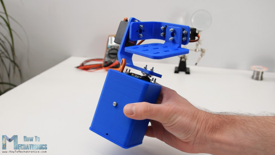
I designed the gimbal using a 3D modeling software. It consists of 3 MG996R servo motors for the 3-axis control, and a base on which the MPU6050 sensor, the Arduino and the battery will be placed.
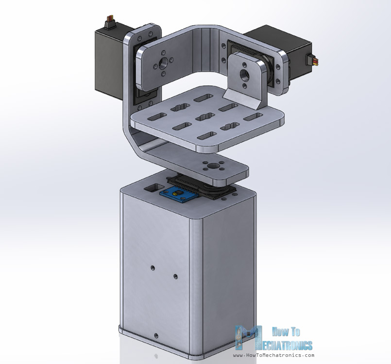
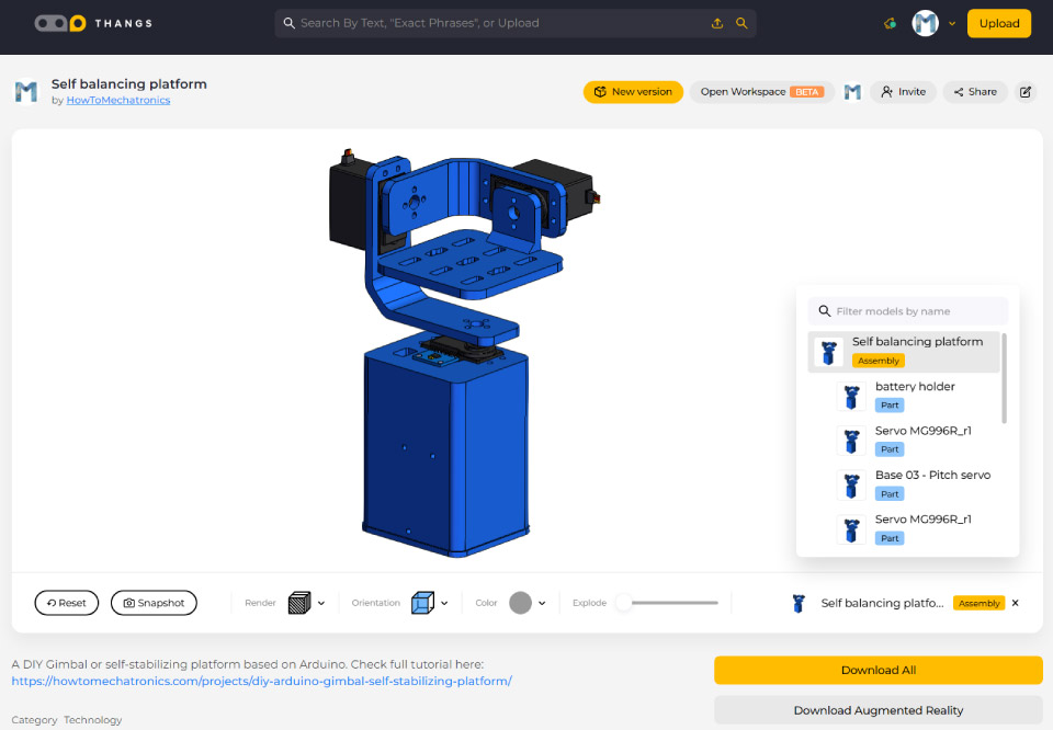
You can find and download this 3D model, as well as explore it in your browser at Thangs.
STL Files:
Using my Creality CR-10 3D printer, I 3D printed all the parts and they came of just perfect.
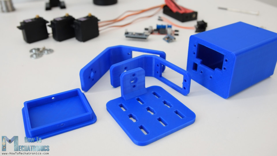
Assembling
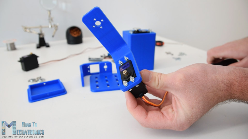
Assembling the gimbal was quite easy. I started with installing the Yaw servo. Using M3 bolts and nuts I secured it to the base.
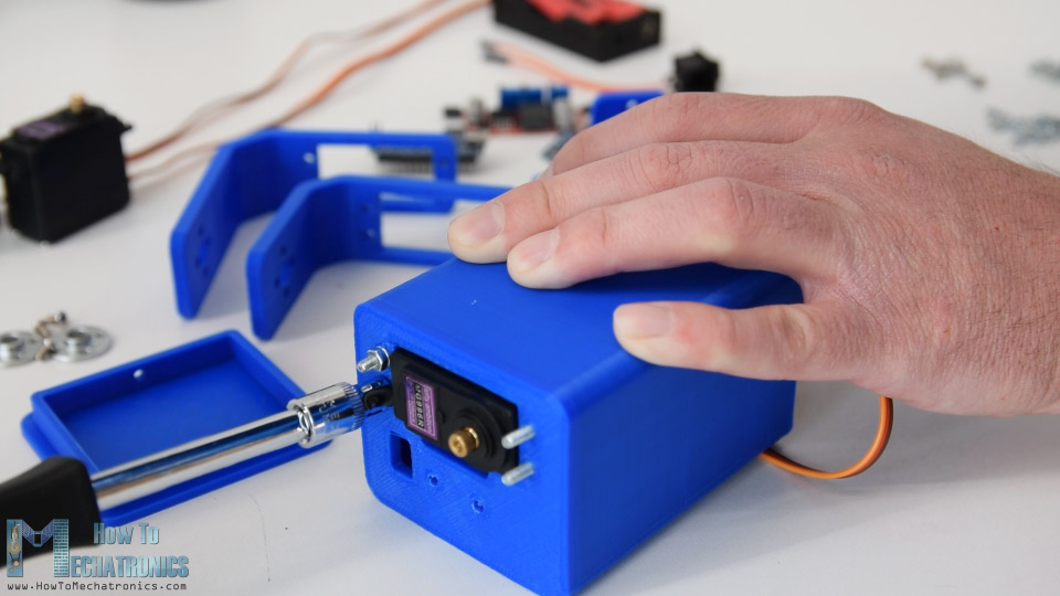
Next, using the same method I secured the Roll servo. The parts are specifically designed to easily fit the MG996R servos.
For connecting the parts to each other I used the round horns which come as accessories with the servos.
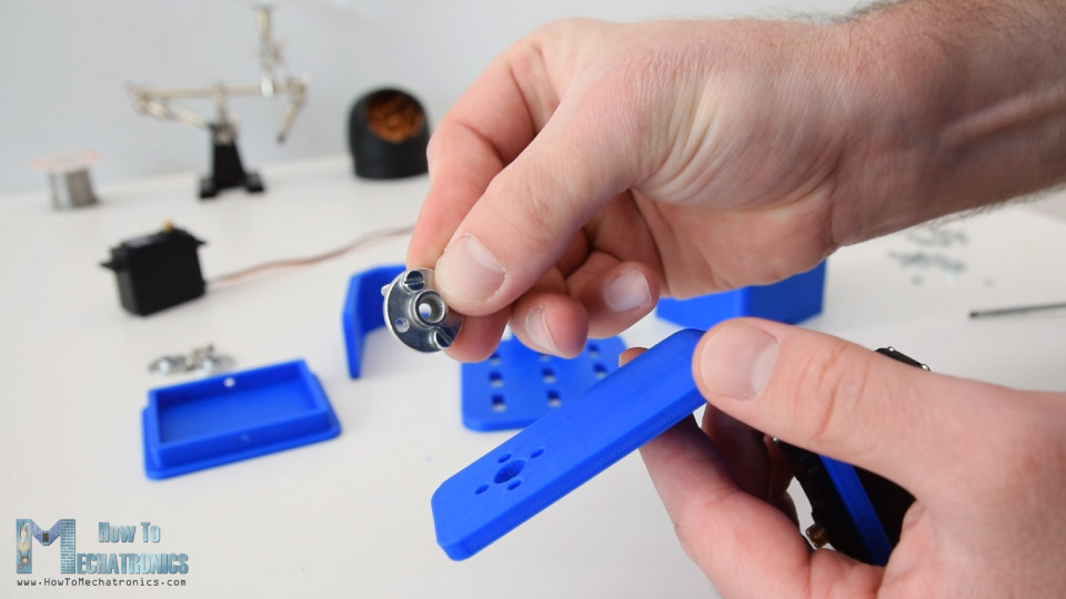
First, we need to secure the round horn to the base with two bolts, and then attach it to the previous servo using another bolt.
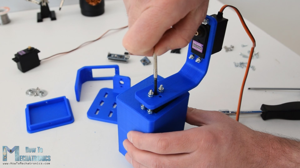
I repeated this process for assembling the rest of the components, the Pitch servo and the top platform.
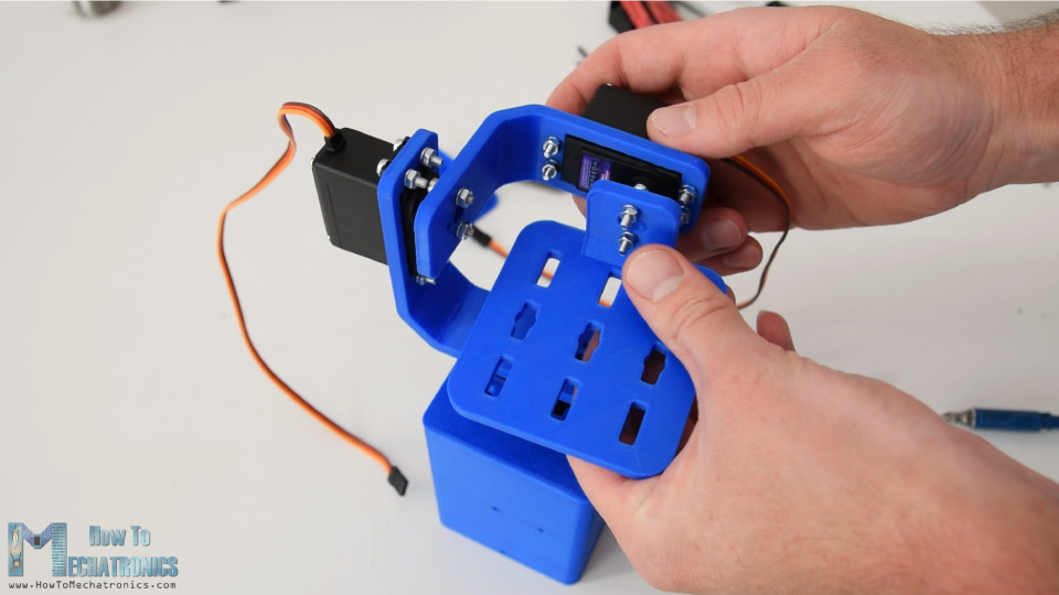
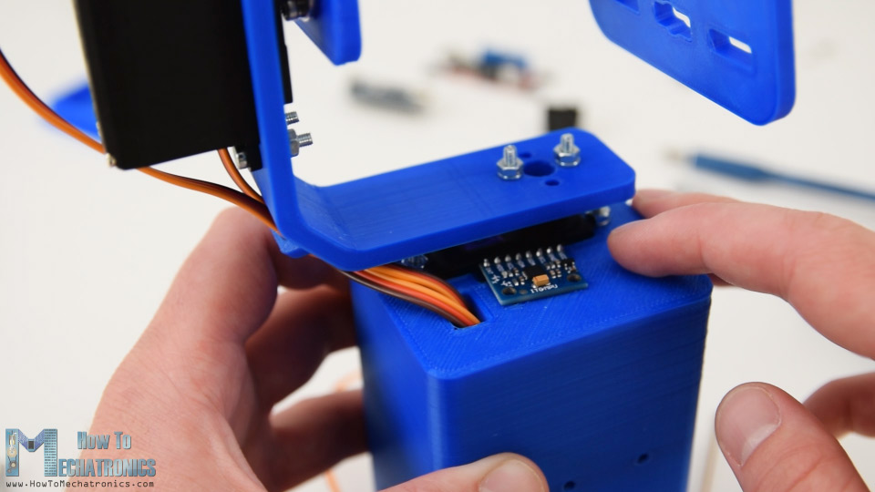
Next, I passed the servo wires through the holders openings in order to keep them organized. Then I inserted the MPU6050 sensor and secured it on the base with a bolt and a nut.
For powering the project, I used 2 Li-ion batteries which I placed in this battery holder. I secured the battery holder to the base using two bolts and nuts.
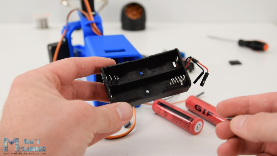
The 2 Li-ion batteries will produce around 7.4V, but we need 5V for powering the Arduino and the servos.
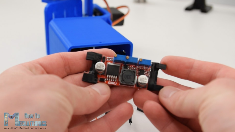
That’s why I used a buck converter which will convert 7.4V to 5V.
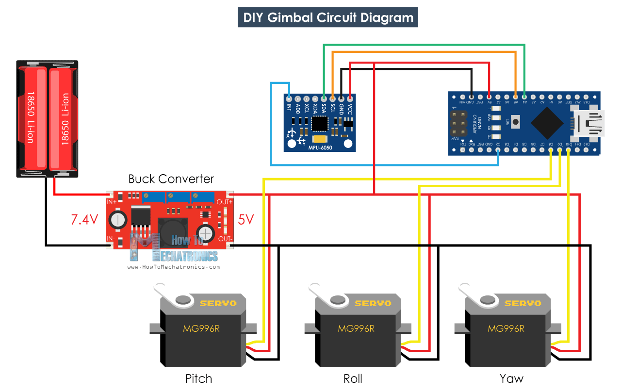
Arduino Gimbal Circuit Diagram
What’s left now, is to connect everything together. Here’s the circuit diagram of this project and how everything needs to be connected.
You can get the components needed for this Arduino Tutorial from the links below:
- MPU6050 IMU ………………………………. Amazon / Banggood / AliExpress
- MG996R Servo ………………………………. Amazon / Banggood / AliExpress
- Buck Converter ……………………………… Amazon / Banggood / AliExpress
- Arduino Board …………………………..….. Amazon / Banggood / AliExpress
- Breadboard and Jump Wires ………… Amazon / Banggood / AliExpress
Disclosure: These are affiliate links. As an Amazon Associate I earn from qualifying purchases.
At the end I squeezed the electronics components and the wires into the base, and covered them using this cover at the bottom.
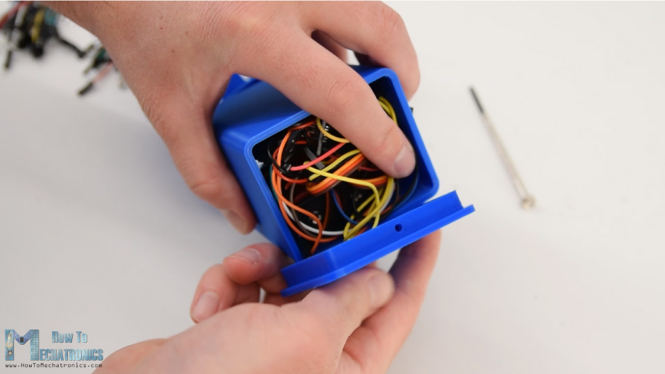
With this the self-balancing platform or the Arduino gimbal is done and it works well as expected. What’s left is to take a look at the program.
Arduino Code
The Arduino code for this example is a modification of the MPU6050_DMP6 example from the i2cdevlib library by Jeff Rowberg.
Here’s you can download the code:
Code description: So, we are using the output readable yaw, pitch and roll.
// Get Yaw, Pitch and Roll values
#ifdef OUTPUT_READABLE_YAWPITCHROLL
    mpu.dmpGetQuaternion(&q, fifoBuffer);
    mpu.dmpGetGravity(&gravity, &q);
    mpu.dmpGetYawPitchRoll(ypr, &q, &gravity);

    // Yaw, Pitch, Roll values - Radians to degrees
    ypr[0] = ypr[0] * 180 / M_PI;
    ypr[1] = ypr[1] * 180 / M_PI;
    ypr[2] = ypr[2] * 180 / M_PI;

    // Skip 300 readings (self-calibration process)
    if (j <= 300) {
      correct = ypr[0]; // Yaw starts at random value, so we capture last value after 300 readings
      j++;
    }
    // After 300 readings
    else {
      ypr[0] = ypr[0] - correct; // Set the Yaw to 0 deg - subtract  the last random Yaw value from the currrent value to make the Yaw 0 degrees
      // Map the values of the MPU6050 sensor from -90 to 90 to values suatable for the servo control from 0 to 180
      int servo0Value = map(ypr[0], -90, 90, 0, 180);
      int servo1Value = map(ypr[1], -90, 90, 0, 180);
      int servo2Value = map(ypr[2], -90, 90, 180, 0);

      // Control the servos according to the MPU6050 orientation
      servo0.write(servo0Value);
      servo1.write(servo1Value);
      servo2.write(servo2Value);
    }
#endifCode language: PHP (php)
Once we get the values, first we convert them from radians to degrees.
// Yaw, Pitch, Roll values - Radians to degrees
    ypr[0] = ypr[0] * 180 / M_PI;
    ypr[1] = ypr[1] * 180 / M_PI;
    ypr[2] = ypr[2] * 180 / M_PI;Code language: JavaScript (javascript)
Then we wait or make 300 readings, because the sensor is still in self-calibration process during this time. Also, we capture the Yaw value, which at the beginning is not 0 like the Pitch and Roll values, rather it’s always some random value.
// Skip 300 readings (self-calibration process)
    if (j <= 300) {
      correct = ypr[0]; // Yaw starts at random value, so we capture last value after 300 readings
      j++;
    }Code language: JavaScript (javascript)
After the 300 readings, first we set the Yaw to 0 by subtracting the above captured random value. Then we map the values of the Yaw, Pitch and Roll, from – 90 to +90 degrees, into values from 0 to 180 which are used for driving the servos.
// After 300 readings
    else {
      ypr[0] = ypr[0] - correct; // Set the Yaw to 0 deg - subtract  the last random Yaw value from the currrent value to make the Yaw 0 degrees
      // Map the values of the MPU6050 sensor from -90 to 90 to values suatable for the servo control from 0 to 180
      int servo0Value = map(ypr[0], -90, 90, 0, 180);
      int servo1Value = map(ypr[1], -90, 90, 0, 180);
      int servo2Value = map(ypr[2], -90, 90, 180, 0);

      // Control the servos according to the MPU6050 orientation
      servo0.write(servo0Value);
      servo1.write(servo1Value);
      servo2.write(servo2Value);
    }Code language: JavaScript (javascript)
Finally using the write function, we send these values to the servos as control signals. Of course, you can disable the Yaw servo if you want just stabilization for the X and Y axis, and use this platform as camera gimbal.
Please note this far from good camera gimbal. The movements are not smooth because these servos are not meant for such a purpose. Real camera gimbals use a special type of BLDC motors for getting smooth movements. So, consider this project only for educational purpose.
That would be all for this tutorial, I hope you enjoyed it and learned something new. Feel free to ask any question in the comments section below and don’t forget to check my collection of Arduino Projects.
Great job! Is it possible to use 360° servos (continuous rotation) instead of the 180°?
360 degrees servos don’t have position sensor, so you can’t use them for this project as it is.
Reading your project to learn to use MPU6050 and found a problem.
The mpu6050 library is updated after the guide is written so your code will be stuck at setup and won’t work.
After a few hours, I found out it is because they add a new calibration function and you need to call them first.
So, add these three lines
// Calibration Time: generate offsets and calibrate our MPU6050
mpu.CalibrateAccel(6);
mpu.CalibrateGyro(6);
mpu.PrintActiveOffsets();
right before
mpu.setDMPEnabled(true);
and everything will work like a charm.
Also while looking at my serial, I found out that it takes a long time for my ypr value to be stabilized. About 5~10 seconds. Is this normal?
Hello Dejan,
Thank you for this step by step project.
I am running into an issue with the motors, wherein the motors start spinning in one direction continuously. Everything starts off as expected with the yaw, pitch and roll motors moving with the gyro. But after a point, the motors start a continuous spin and seem out of control.
Any thoughts on how I can troubleshoot?
Chris
Hello, I tried to make the exact same gimbal at this project, but I met some problems of the components you used.. Can you let me know the spec of the things that you did not mentioned? I wrote the lists below.
– Capacity of 18650 batteries (ex, 2600mA)
– Length of M3 bolts
– Action camera you used
– Diameter of the round horns
Thanks for reading my comment.
Hey, the capacity of the batteries is not that much important, that just defines how much long it can last.
The length of the M3 bolts that I used is like 12 or 14mm.
The action camera is also doesn’t matter. Also don’t expect with this setup to get nice and smooth footage, this project is only showing a simplified concept of working.
The round horns come as accessories with the servo motors.
Quick question. Wouldn’t you also need to connect the GND from your Buck Converter to the Arduino? Also, your schematic diagram doesn’t appear to show how you’re supplying PWR to your Arduino board. Is this also coming from your batteries? Or do you have a separate power supply?
Yeah, the GND from the Buck Converter should be connected to the Arduino GND. Here, in the circuit diagram, the Arduino is powered via the 5V pin which is connected to the Buck Converter 5V output.
Wow!! I tried writing my own code using the basics of mpu data reading but the issue was unstable literally unstable even after all the conditions I applied, this is the only code based on jeff rowberg’s library and Dejan’s code innovation that is so smooth. You gained a fan because wasted so much time to stable this. (even trying offsets!!)
good work, The IMU has to be in part where camera is mounted not on handle as the objective is to stabilize it !
Thanks for the input.
great project …..great steps explanations
can you do a quadcopter project featuring the MPU6050?
This is fantastic – this is the only code where I was able to get a stable yaw reading off the MPU-6050, once it settles down, its really stable, the quarternion adjustments really work !
The only though I would add here is a fuse on the battery line just in case of a short.
Great to hear that. Thanks for the input!