In this tutorial we will learn how rotary encoder works and how to use it with Arduino. You can watch the following video or read the written tutorial below.
Overview
A rotary encoder is a type of position sensor which is used for determining the angular position of a rotating shaft. It generates an electrical signal, either analog or digital, according to the rotational movement.
There are many different types of rotary encoders which are classified by either Output Signal or Sensing Technology. The particular rotary encoder that we will use in this tutorial is an incremental rotary encoder and it’s the simplest position sensor to measure rotation.
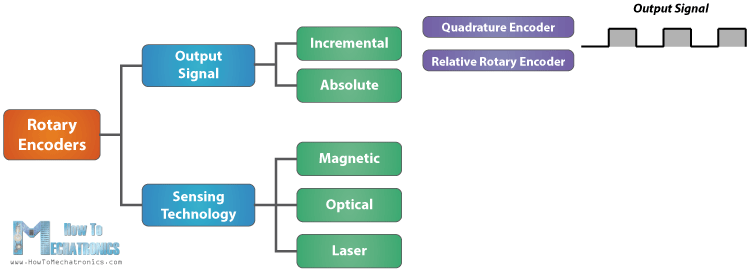
This rotary encoder is also known as quadrature encoder or relative rotary encoder and its output is a series of square wave pulses.
How Rotary Encoder Works
Let’s take a closer look at the encoder and see its working principle. Here’s how the square wave pulses are generated: The encoder has a disk with evenly spaced contact zones that are connected to the common pin C and two other separate contact pins A and B, as illustrated below.
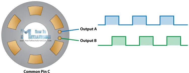
When the disk will start rotating step by step, the pins A and B will start making contact with the common pin and the two square wave output signals will be generated accordingly.
Any of the two outputs can be used for determining the rotated position if we just count the pulses of the signal. However, if we want to determine the rotation direction as well, we need to consider both signals at the same time.
We can notice that the two output signals are displaced at 90 degrees out of phase from each other. If the encoder is rotating clockwise the output A will be ahead of output B.
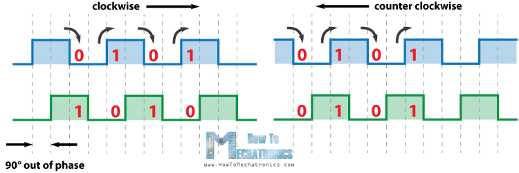
So if we count the steps each time the signal changes, from High to Low or from Low to High, we can notice at that time the two output signals have opposite values. Vice versa, if the encoder is rotating counter clockwise, the output signals have equal values. So considering this, we can easily program our controller to read the encoder position and the rotation direction.
Rotary Encoder Arduino Example
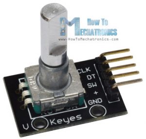
Let’s make a practical example of it using the Arduino. The particular module that I will use for this example comes on a breakout board and it has five pins. The first pin is the output A, the second pin is the output B, the third pin is the Button pin and of course the other two pins are the VCC and the GND pin.
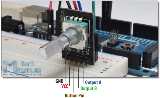
We can connect the output pins to any digital pin of the Arduino Board.
You can get the components needed for this Arduino Tutorial from the links below:
- Rotary Encoder Module………………. Amazon / Banggood / AliExpress
- Arduino Board …………………………… Amazon / Banggood / AliExpress
- Breadboard and Jump Wires ……… Amazon / Banggood / AliExpress
Disclosure: These are affiliate links. As an Amazon Associate I earn from qualifying purchases.
Source Code
Here’s the Arduino code:
/*     Arduino Rotary Encoder Tutorial
 *
 *  by Dejan Nedelkovski, www.HowToMechatronics.com
 *
 */

 #define outputA 6
 #define outputB 7

 int counter = 0;
 int aState;
 int aLastState;

 void setup() {
   pinMode (outputA,INPUT);
   pinMode (outputB,INPUT);

   Serial.begin (9600);
   // Reads the initial state of the outputA
   aLastState = digitalRead(outputA);
 }

 void loop() {
   aState = digitalRead(outputA); // Reads the "current" state of the outputA
   // If the previous and the current state of the outputA are different, that means a Pulse has occured
   if (aState != aLastState){
     // If the outputB state is different to the outputA state, that means the encoder is rotating clockwise
     if (digitalRead(outputB) != aState) {
       counter ++;
     } else {
       counter --;
     }
     Serial.print("Position: ");
     Serial.println(counter);
   }
   aLastState = aState; // Updates the previous state of the outputA with the current state
 }Code language: Arduino (arduino)
Description of the code: So first we need to define the pins to which our encoder is connected and define some variables needed for the program. In the setup section we need to define the two pins as inputs, start the serial communication for printing the results on the serial monitor, as well as read the initial value of the output A and put the value into the variable aLastState.
Then in the loop section we read the output A again but now we put the value into the aState variable. So if we rotate the encoder and a pulse is generated, these two values will differ and the first “if” statement will become true. Right after that using the second “if” statement we determine the rotation direction. If the output B state differ from the output A state the counter will be increased by one, else it will be decreased. At the end, after printing the results on the serial monitor, we need to update the aLastState variable with aState variable.
That’s all we need for this example. If upload the code, start the Serial Monitor and start rotating the encoder we will start getting the values in the serial monitor. The particular module that I have makes 30 counts each full cycle.
Learn more: Ultrasonic Sensor HC-SR04 and Arduino – Complete Guide
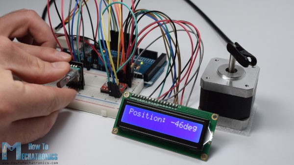
Example 2 – Controlling a Stepper Motor Using a Rotary Encoder
In addition to this basic example, I made one more example of controlling a stepper motor position using the rotary encoder.
Here’s the source code of this example:
/*     Stepper Motor using a Rotary Encoder
 *
 *  by Dejan Nedelkovski, www.HowToMechatronics.com
 *
 */

 #include <LiquidCrystal.h> // includes the LiquidCrystal Library
 LiquidCrystal lcd(1, 2, 4, 5, 6, 7); // Creates an LC object. Parameters: (rs, enable, d4, d5, d6, d7)

// defines pins numbers
 #define stepPin 8
 #define dirPin  9
 #define outputA 10
 #define outputB 11

 int counter = 0;
 int angle = 0;
 int aState;
 int aLastState;

void setup() {
  // Sets the two pins as Outputs
  pinMode(stepPin,OUTPUT);
  pinMode(dirPin,OUTPUT);
  pinMode (outputA,INPUT);
  pinMode (outputB,INPUT);

  aLastState = digitalRead(outputA);
  lcd.begin(16,2); // Initializes the interface to the LCD screen, and specifies the dimensions (width and height) of the display }

}
void loop() {

  aState = digitalRead(outputA);

  if (aState != aLastState){
     if (digitalRead(outputB) != aState) {
       counter ++;
       angle ++;
       rotateCW();
     }
     else {
       counter--;
       angle --;
       rotateCCW();
     }
     if (counter >=30 ) {
      counter =0;
     }

     lcd.clear();
     lcd.print("Position: ");
     lcd.print(int(angle*(-1.8)));
     lcd.print("deg");
     lcd.setCursor(0,0);

   }
  aLastState = aState;
}

void rotateCW() {
  digitalWrite(dirPin,LOW);
    digitalWrite(stepPin,HIGH);
    delayMicroseconds(2000);
    digitalWrite(stepPin,LOW);
    delayMicroseconds(2000);
}
void rotateCCW() {
  digitalWrite(dirPin,HIGH);
    digitalWrite(stepPin,HIGH);
    delayMicroseconds(2000);
    digitalWrite(stepPin,LOW);
    delayMicroseconds(2000);
}
Code language: Arduino (arduino)
Feel free to ask any question in the comments section below.
Can a rotary encoder be used to rotate a stepper between 2 limit switches and still allow random turns of the encoder between those 2 points. I guess what I’m asking is, can the encoder be controlled to have a max and min with freedom of movement CW or CCW between those 2 points but not be able to push the stepper beyond those limits? I’m using an Arduino Uno and Easy Driver
Sure it can. You can define your min and max points by how much steps the motor should make for reaching those min and max position. When you reach those points the input from the encoder will no longer move the stepper. You will have to figure out the logic and code it.
Hi everyone!
Im about to build a measurement tool to measure length of different objects. Can I use this technology to measure lenght?
Also, what screen is that? I like it, where can I find a similar?
Hey, theoretically yes, you could make a length measuring device with this technology.
All was simplicity and harmony… until I went and added an I2C OLED display. I expect the delay in refreshing the screen is terminally interfering with the timing of the pulse detection.
I am using an Arduino NANO and a shield that means I only have pins 9, 10 and 11 available so I cannot attach an ISR… I so wanted to use the rotary encoder… Poopy buttons for me then 🙁
Thanks for a really good, simple tutorial though 🙂
hi,
How set encoder in home position after unplanned power off ?
The only way I could that happening is if some way move the encoder back to 0, from where is’s last stored position was.You could use a servo or some other motor. This would take a lot of work. I presume you want the “knob” to point back on home on power up?
/s/WP
Each time the encoder is powered on it begins counting from zero, regardless of where the shaft is or its previous position.
how we start from previous position of the encoder after power of also.
Well the encoder itself doesn’t have such a capability. However, you could achieve that by storing it’s position in the EEPROM of the Arduino. So the next power up you will read the stored value from the EEPROM and continue with it.
Hi Dejan,
first of all Thanks for reply .
i am newbie, using Arduino Atmega 2560.
i have connected Encoder 5540 to Dc motor shaft , the incremental encoder has two channels connected to I/O pins .The encoder reading the motor position,( encoder feedback )how to store in EEPROM.
please give me any sample code or routine .
Regards,
Naresh.
have a nice day ..!!
The encoder code in your example only accounts for half of the encoder ticks. This is because the counter is only updated after the A pin changed, not when any of the two changed. It still may be ok for your application but it can’t be considered good if you want to take advantage of the full resolution of the encoder.
Hi Great tutorial,,,, I am not sure of all the components on the display. There is the Arduino, the screen, the rotary s witch, the breadboard, jumpers, But there is a little item with what looks like a heat sink,,,,I don’t know what that is… Also where do I find the wiring diagram?
Many thanks for an excellent explanation. Thumbs up and subscribed.
Cheers
john nielsen
Hi there and thanks! The item you are talking about is in the second example, and that’s the A4988 stepper motor driver. For more details on it and how to control stepper motors using the Arduino you can check my particular tutorial for it. Cheers! 🙂
Nice tutorial my friends. Just keep update.
Thank you Sir. You helped me a lot. Now a Fanuc A860-0201-T001 Encoder from 1990 is working with my project.
I’m glad to hear this, thanks!
Hi Dejan,
Thank you for such a great tutorials. Thank you for sharing your knowledge and make a better world.
Eng Apache
Your tutorial is very helpful to me.
But I need a very precise motor to get 1 degree per step. Do you have an idea of how to achieve it? So have I will to use a reduction to achieve this?
Big regads
Поздрав
Well maybe you could use microstepping in order to increase the resolution of the motor, or as you said use additional gear box with an output ratio of 1.8::1.0.
This method only uses half the resolution of the rotary encoder as there are four different states per cycle (11, 10, 00, 01) but you only check for TWO changes in each direction (if from 10 to 00 or from 01 to 11 –> counter++; if from 11 to 01 or from 00 to 10 –> counter–). So you miss out 11 to 10, 00 to 01, 01 to 00 and 10 to 11.
To get the full resolution, you have to check every change. Example code (not easy to read but efficient and compact):
##############################################
int counter;
bool prevA = 1, prevB = 1;
void loop() {
bool A = digitalRead(pin_rotaryA), B = digitalRead(pin_rotaryB);
if (B != prevB) counter += (B-prevB) * (A ? +1 : -1);
else if (A != prevA) counter += (A-prevA) * (B ? -1 : +1);
else return; //nothing changed: exit
prevA = A;
prevB = B;
Serial.println(counter);
}
##############################################
This works really great if you turn the rotary encoder at a normal speed. But if you turn it too fast or you do other stuff in your loop() that takes longer time you will miss a step and it will jump from 11 to 00 or from 10 to 01. Then it can’t know, which direction it was turned, so the counter will get slightly incorrect.
But you can counter that by checking, which direction it was turned before and increasing or decreasing the counter accordingly by 2.
Or you can use interrupts instead of checking the state of the pins in the loop() to ensure that no step is missed.
That’s a great remark. Thanks for the contribution!
A clearer, yet more efficient way to get the full resolution of the encoder, is this. It’s more efficient because it doesn’t use any integer arithmetic, and it takes advantage of the “short-circuit” evaluation rule of logical operators, which will skip most of the code in most cases.
##############################################
int counter=0;
byte encoderSt=0;
void loop()
{
byte a = digitalRead( pinA );
byte b = digitalRead( pinB );
byte st = (b<<1) | a;
if ( encoderSt != st )
{
if ( (encoderSt==0 && st==2) || (encoderSt==1 && st==0) || (encoderSt==2 && st==3) || (encoderSt==3 && st==1) ) counter– ;
else counter++;
Serial.println( counter );
encoderSt = st;
}
}
##############################################
More efficient code using only binary operators
##############################################
int counter;
bool prevA = 1, prevB = 1;
void loop() {
bool A = digitalRead(pin_rotaryA), B = digitalRead(pin_rotaryB);
counter += (A ^ prevA) | (B ^ prevB)? A ^ prevB ? 1 : -1 : 0;
prevA = A;
prevB = B;
Serial.println(counter);
}
##############################################
Hi I am from Argentina. Great project !!
I followed your steps and it works. Although I have a problem! If I turn it slow, it does well the counter, but if I do a quick turn, it is uncontrolled and repeats steps!
I used an encoder from an epson printer.
Could it be because the encoder has a lot of resolution?
Will it be able to work with this Encoder?
From already thank you very much!!
Greetings from Argentina!!
The problem might be in the code which isn’t that much optimized. It’s just an simple example code and it probably needs so optimization in order to achieve better results.
Hi Dejan!
I think there is a small bug in the first code example. The if statement ” if (aState != aLastState)” captures both rising and falling edge of the encoder’s clock pulse. This means that one rotary encoder step will make two changes to counter. If you replace “if (aState != aLastState)” with “if (aState > aLastState)” you will count only rising edges.
I agree. Counter changes twice for one step of shaft if you use the condition (aState != aLastState). If you use (aState > aLastState) or (aState < aLastState), it works for me well. Both conditions "” are possible because CLK edge changes this way:
1 -> 0 -> 1.
I do not think anyone can make this as the ButtonPin goes nowhere. A circuit diagram is needed as we all use different stepper drivers. Best is to write this in Instructables.
At first, I was excited, but now after 4 hours I only got a headache.
I didn’t use the ButtonPin in the examples but it’s just simple push button. As for the stepper example, you can find a circuit schematics on my detailed tutorial for the A4988 driver.
Great project almost what I need. Is it possible that the last position of the motor (say 68 degrees) is remembered by the arduino? So that If the arduino is powered down and then restarted it would “remember” the position and read 68 on the LCD?
Yes, it’s possible. You can store data permanently using the EEPROM of the Arduino.
Hi Dejan,
Thank you for your great tutorials. also for I2c and SPI.
But I have a question regarding encoder reading.
My increments are always 2 instead of 1. I also added a couple of circuitry to eliminate the debounce but no way.
Could you please help me ?
Thanks. Well it could be a faulty encoder…
It could be that the encoder that Dejan was using had only 2 transitions per detent and yours has 4? As you turn the knob, the 2 pin states go 00, 10, 11, 01, etc. Some encoders have the detents when the pins are at 11 and others when it is at 00. Some have detents at 00 AND 11 and I suspect Dejan has one of these.
So, Dejan’s starts, perhaps at 00 and one detent (2 transitions, ie 10, 11) takes him to 11, so that’s one “step” in his program. On his next click around, it transitions to 01 then 00 again, making another “step”. Yours will be making starting from 00 and making 4 transitions, ie 10, 11, 01, 00, so his code is counting 2 “steps” on your encoder and only one on his. Yours might be set to 11 in a detent, not 00, but the principle is the same. You will have to hack this code a little to make it ignore the extra step.
Hi!
Great project, really enjoyed it!
I just wanted to know what’s the equation you used to find out the shaft angle. Was it based on the ppr? I’m working with a 1024ppr incremental encoder and I haven’t been able to find a match for the shaft angle and counter value.
Thanks!
Thanks. Yes, the equation is based on the ppr. In my case, the rotary encoder had 30 ppr.
Hi Dejan,
I am Interested and wanna to build this project, could you please given me the details of schematic and modules there are used.
Thanks.
Regards,
Leem.
Well everything is already explained. You can figure out how to connect the encoder from this tutorial and if you check my Stepper Motor Control tutorial you can find the circuit schematics for connecting the driver and the stepper motor.
Hi, thanks for your great work…I am now working on a project using rotary encoder with LCD display of the angle. Have I have your full schematic diagram of Example 2? Thank you
Thanks! Well I don’t have the particular circuit schematics but I have separate circuit schematics for each components, the rotary encoder, the LCD display and the servo motor control so you should not have any problem with it.
I am using the 28BYJ-48 Step Motor which is different from the one you used it in the video. 28BYJ stepper motor is connected to Arduino through 4 digital pins but the one you used only connected via 2 pins (stepPin and dirPin). Do you have any idea of changing the code for 28BYJ-48 motor?
I’m a retired EE and amateur radio operator (call N1ABE) with a lot of experience; however, as part of that experience I’ve learned not to reinvent the wheel. That said, I am designing an Arduino Uno based direct digital synthesizer using a DDS9850 module I got via Amazon. So far I have been able to use it via the serial port. I was originally going to use a compiled robot basic app but I wanted a stand-alone set up, preferably battery powered. What came to mind was using a rotary encoder to set the frequency. Unfortunately there wasn’t much on the Arduino web site about them so I did a search and found your web site. Voila! You have exactly the code I was looking for, thank you. There were other code examples elsewhere using interrupts but I wanted a version that didn’t use them. I copied yours and it compiled without error. When I get the encoders I will integrate your code into mine. I am probably going to use a separate push button since the encoders I am getting do not have an integral switch. I am not at this time looking to add a display because my goal is to keep the project simple and will set the frequency with an o’scope. The DDS produces a stable signal up to 40 MHz and will make a nice lab bench signal source to compliment my home brew function generator. Once my project is done I will be more than happy to share my design with you and intend to attribute you in my final code.
Great, I’m glad you found my article useful!
Can we use rotary encoder to measure linear length?
Sure.
Well done friend!!! i understood it very well. I had a problem in machine elecronic. Can you solve it??
I work in a Power Grid where there is HVDC station. In this HVDC station, there are Thyristor (SCR) valves bank. During AC to DC conversion, this Thyristor gets heated. Hench, a cooling system is incorporate for cooling this Thyristor. Cooling system consist of 4 nos cooler with water spray nozzle at top and axial fan motor at bottom, for forced air cooling.
This four cooler are in auto mode. That is, when the temperature is high, the coolers begin to come in service one by one to maintain the temperature in preset limit & vice versa.
When the temperature begins to drop, the coolers begins to cutoff one by one ( on first in first out biases ) by sending commands to PLC.
There are dampers installed in each coolers. This dampers had three position : open, middle & closed. Lets assume the 4 coolers are in service now. So when the temperature begin to drop ( due to ambient temperature or power reduced), PLC send command to coolers to close its damper from fully open to half open . Lets assume that PLC sends command to cooler No.1 to close its damper to half. So the cooler no:1 damper motor will rotate the damper shaft and when the damper reaches the half closed position, the position is sense by PLC (by micro switch) and PLC sends stop command to damper motor. Then the PLC will monitors the temperature. If there is further reduce in temperature, the PLC sends command to cooler No:1 damper motor to fully close the damper & put off the spray pump & fan motor. That the main principle of cooling system in HVDC.
Now we are facing a problem that the cooler are not able to operate in auto mode since the damper statues is not send to PLC. Also we are not getting support from OEM.
I had a idea to install a encoder to the damper motor shaft. Note that the damper motor is a slow moving motor.It requires around 3 minutes to move the damper from fully opened to fully closed position ( and Vise-versa). The encoder (in-cooperated with some microprocessor like audrino) will sense the position of damper and sends three position command (Open , middle & close) to PLC.
I want to make a photo type by using a Optical encoder & audrino uno / mega and test it. Can you help me in programming and what type of encoder i shall choose.
Regards
Jameel, India
Thanks Jameel! Your idea sounds good and it might be possible to be done. However I’m sorry but I can’t help you with it as I don’t work on custom projects.
so in your example when you move the encoder one position does that mean your stepper motor has moved 1.8degrees ( 1 step)
if so how does the screen display in 1 degree increments
for instance if you moved the encoder from an initial zero position 1 cycle
should the code print an angle of 1.8 deg to the lcd?
i am quite unsure of the maths you have used
and a real beginner here
That’s true, each encoder position the stepper moves 1 step or 1.8 degrees. When printing the degrees on the LCD I use the steps*1.8 expression to get the degrees. For example, 50 encoder positions, or 50 steps * 1.8 = 90 degrees.
I’m unsure as to why you’re multiplying the angle by 1.8, wouldn’t this make sense if a full rotation consisted of 200 steps (200*1.8 = 360 degrees)? Yet you mention that a full rotation is caused by 30 steps as seen in the counter variable. It seems that the system is obviously able to detect a change smaller than 12 degrees (30*12 = 360 degrees).
For example, one full rotation would bring counter from 0 to 30 and angle from 0 to 30, which would relate to 0 to 54 degrees (30*1.8). I’m wondering where I’m going wrong here.
Any clarification would be great!
Yes, you are correct.
The rotary encoder full cycle is 30 steps. So if one rotary encoder step is one stepper motor step, you would need 200 steps for full motor rotation, or 200/30= 6.666 encoder cycles for 1 motor cycle. According to this you can program the Arduino to do whatever you want.
For instance, if you want 1 encoder cycle to be 1 motor cycle, you need to program the Arduino to send 6.66666 steps to the stepper motor for each step of the encoder and so on…