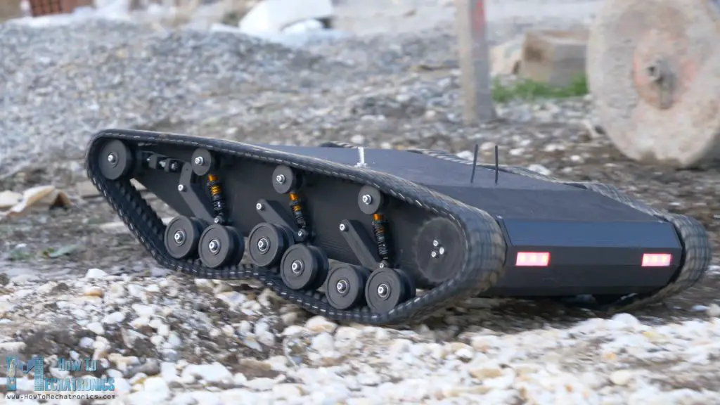
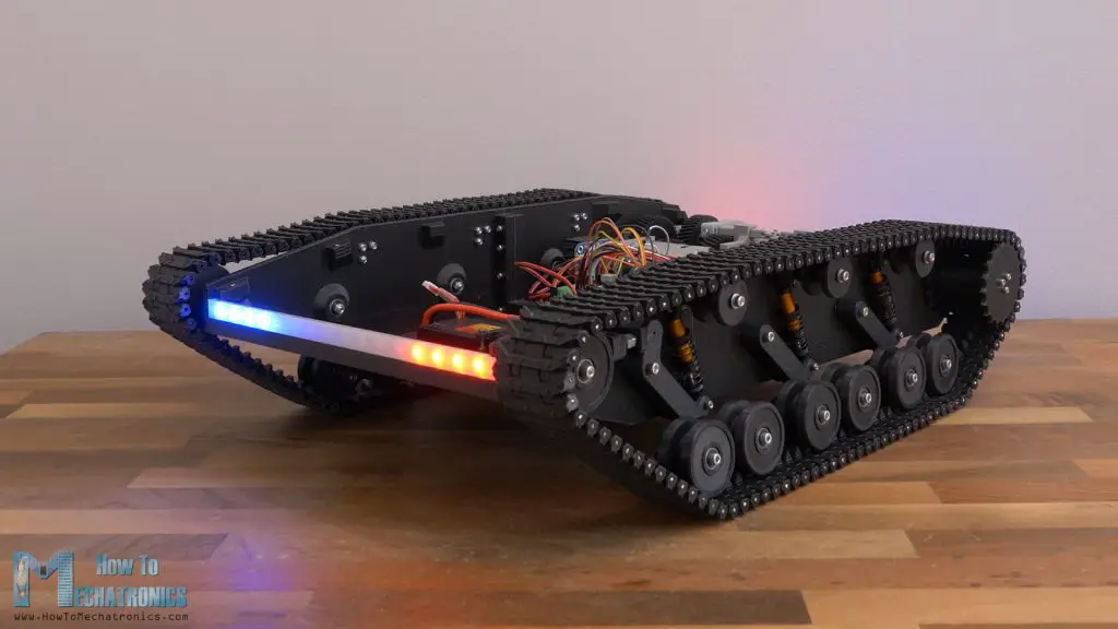
In this tutorial I will show you how I built a beast of a 3D Printed RC tank or a radio-controlled tracked vehicle, featuring clean, all-black design, some cool LED lighting and a dual speed gearbox. That’s right, I specifically designed a gearbox for this tank so I can choose a lower or higher gear depending on terrain or the application that is used for, and so get either higher torque or higher speed.
You can watch the following video or read the written tutorial below.
Overview
If you follow me, you might know that some time ago I already built a 3D printed RC tank, which was cool, but a bit underpowered. That’s why now for this build I’m using 200W DC motor for each track and in combination with this gearbox, the tank has plenty of power to conquer any terrain or to have some fun doing burnouts or donuts with it.
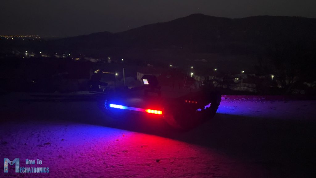
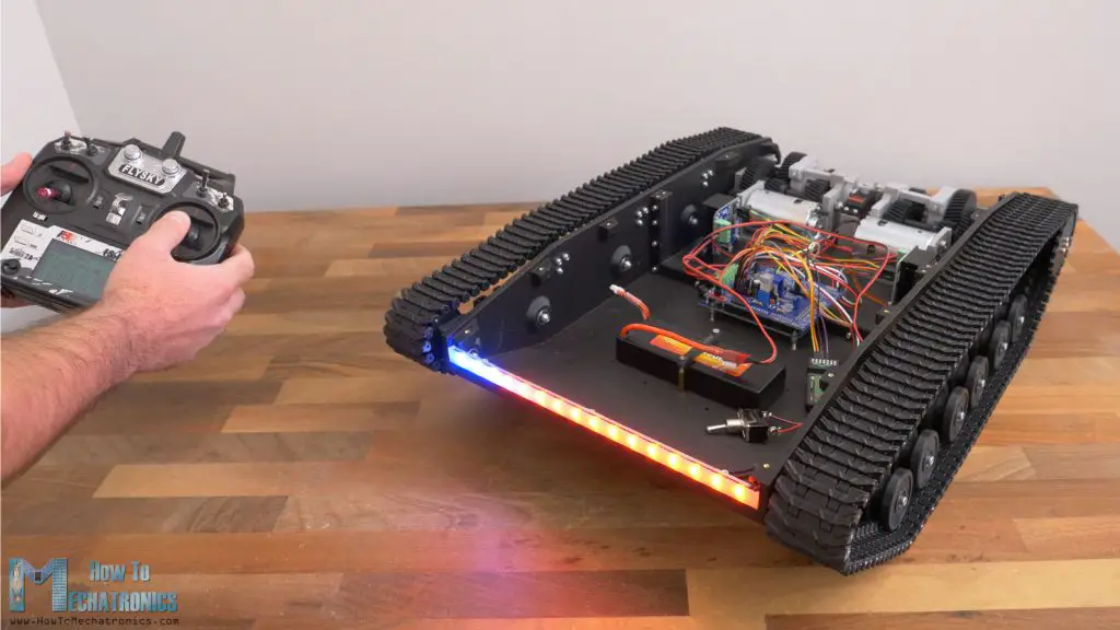
Talking about having fun, I installed an addressable led strip for the lights, which gives endless possibilities for creating stunning light effects. For this video I made a Police lights strobe effect, which is so cool driving around with it, especially at night
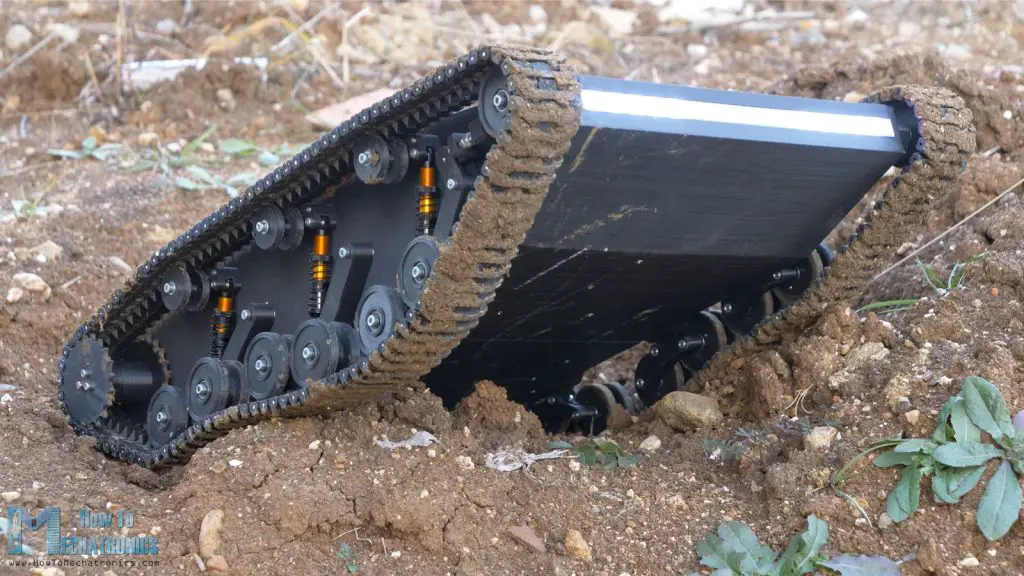
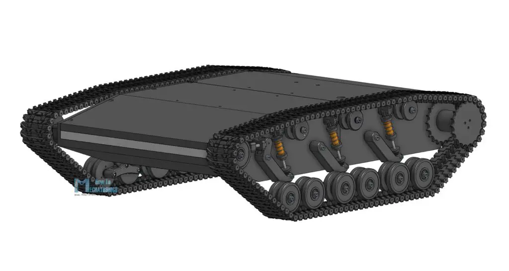
As for the suspension, on each side, the tank is supported on three coil springs and shock absorbers, with two roadwheels for each of them. That allows the vehicle to run smoothly on uneven terrain and climb obstacles while maintaining good contact surface between the tracks and the terrain.
Of course, everything is 3D printed and 3D files are available for downloading, so you can build one on your own.
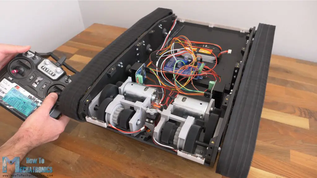
For controlling the tank, I’m using a cheap commercial RC Transmitter which sends commands to it.
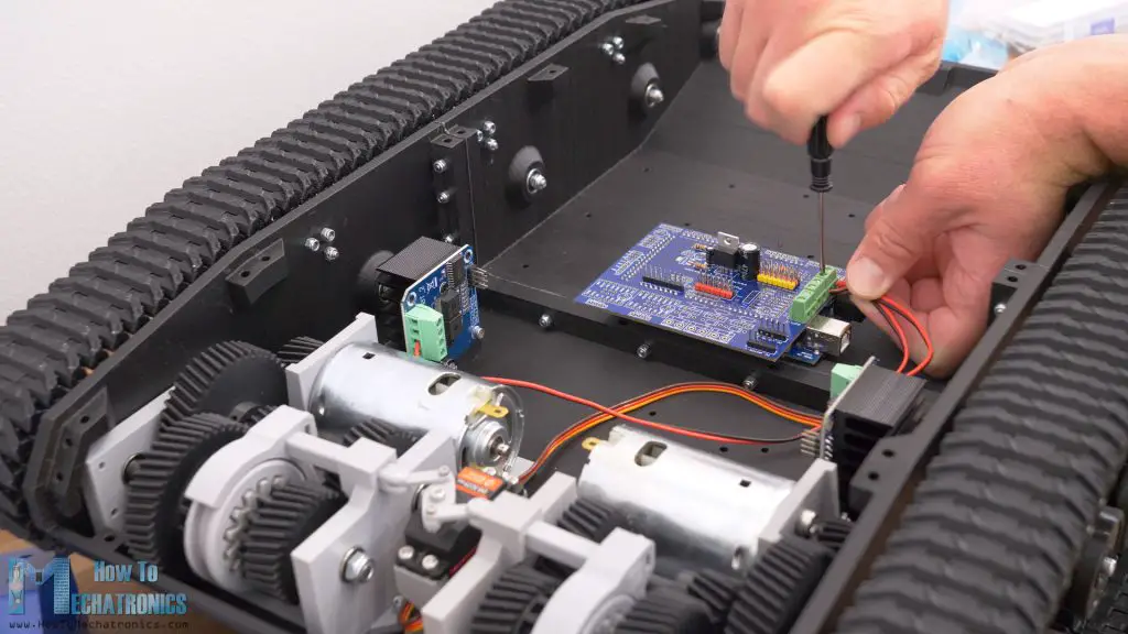
At the tank, there is a suitable RC receiver which receives the commands and sends them to a microcontroller. The brain of this platform is an Atmega2560 microcontroller-based board and for easily connecting everything together I made a custom PCB which can be simply attached on top of the board.
Nevertheless, now buckle up as I will walk you through the entire process of building this RC tank, starting from the design, 3D printing, assembling and connecting the electronics components, to programing the microcontroller.
Designing the RC Tank
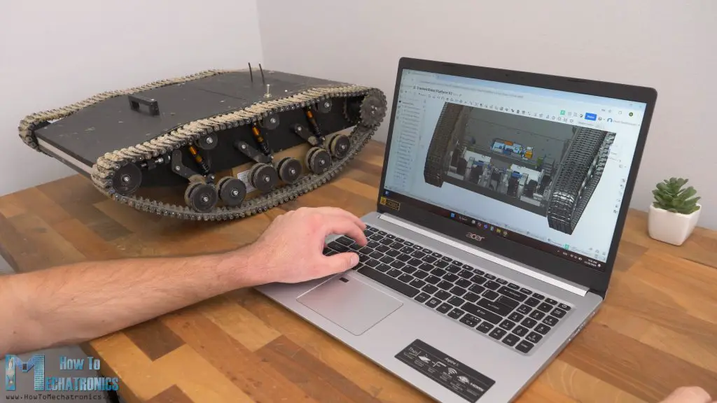
I designed this tank using Onshape.
Onshape is the professional grade cloud native 3D CAD & PDM system that I use for my projects.
I recommend that mechanical engineers and product designers check out Onshape, you and your company can use Onshape Professional for free up to 6 months at https://Onshape.pro/HowtoMechatronics
The initial input parameters for the design were the DC motors, or their dimensions and the RPM. These motors are quite bulky and have 3000 RPM. That’s too high RPM for this tank, so therefore I designed this gearbox, which reduces the speed to two different values.
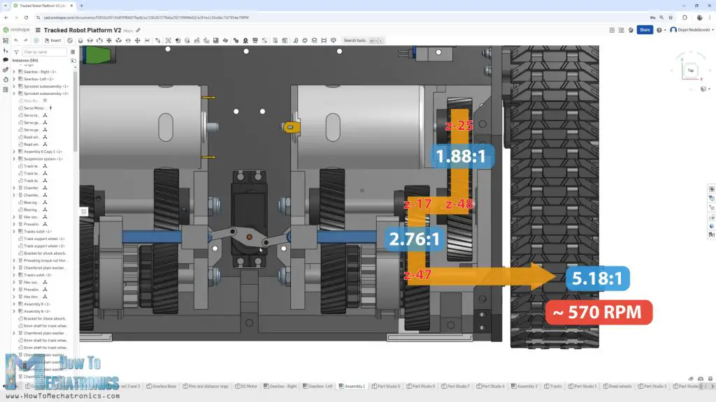
This gearbox works just like a manual transmission in a car works. There is a gear shifter which instead of moving it by hand, here it is moved with the help of a servo motor, and it can choose which of the two output gear sets will be engaged as final output.
The gearbox initial reduction ratio is 1.88:1, which is fixed, and then we can choose either the low gear, which has additional reduction of 2.76:1, or the high gear, which has 1:1 ration. So, in lower gear, the total reduction is 5.2 or that’s around 570RPM, and the higher gear just 1.88 speed reduction, or that’s around 1600RPM.
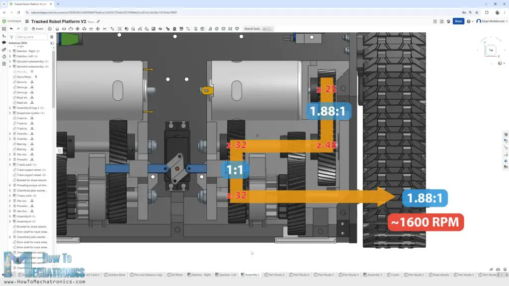
We will see more details how the gearbox works a bit latter in this video we will assemble it.
The next input parameter for the tank design were the RC shock absorbers that I got. They have a length of 70mm when extended, with 15mm travel. I wanted to get a bit greater vertical travel distance for the roadwheels, so I positioned them in this configuration, and got a vertical travel distance of 22mm.
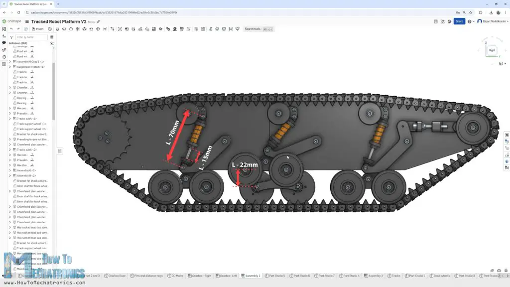
In addition to that, as this is a bogie system where a pair of wheels is attached to that moving axis, the wheels can rotate around that axis and so they can make additional vertical travel. Evidently, that will provide smoother ride and better contact between the track and the surface under it.
If we take a closer look at the front roadwheels, we can notice that they connected with the idler wheel on the front to provide dynamic tension of the track. When the front roadwheels goes up, the track circumference gets smaller and so the tension loosens.
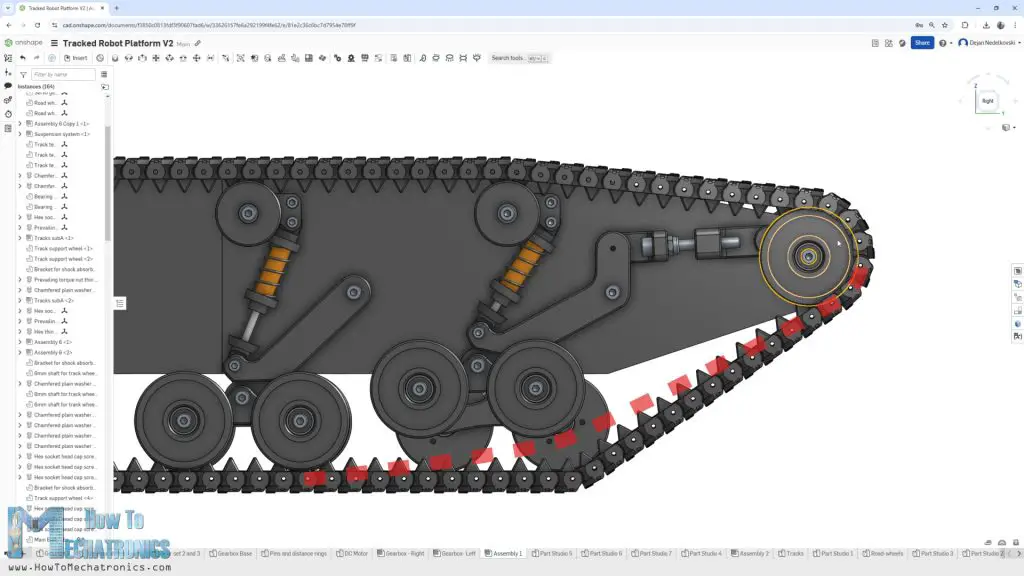
With this setup, when that happens, the idler wheel is pushed forward to tension the track. With this connection we can also tension the track statically, by adjusting this bolt and distance nut.
At the back side, we have the sprocket which is composed of three parts. It has the shaft coupler and left and right section of the sprocket connected all together with three M3 bolts.
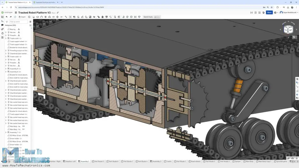
The key dimension here on the sprocket is the pitch because it must match the pitch of the track. The pitch is 11mm here and I chose the sprocket to have 20 teeth which gave me a pitch diameter of the sprocket of around 69mm. The idea for the size of the sprocket was to be big enough so that the track stays out of the tank body.
The 11mm pitch was actually defined by the design of the track link. My goal for the track link was to be as compact as possible and to connectable with the next link with just one additional part or pin, while being strong enough to be made with a 3D printer.
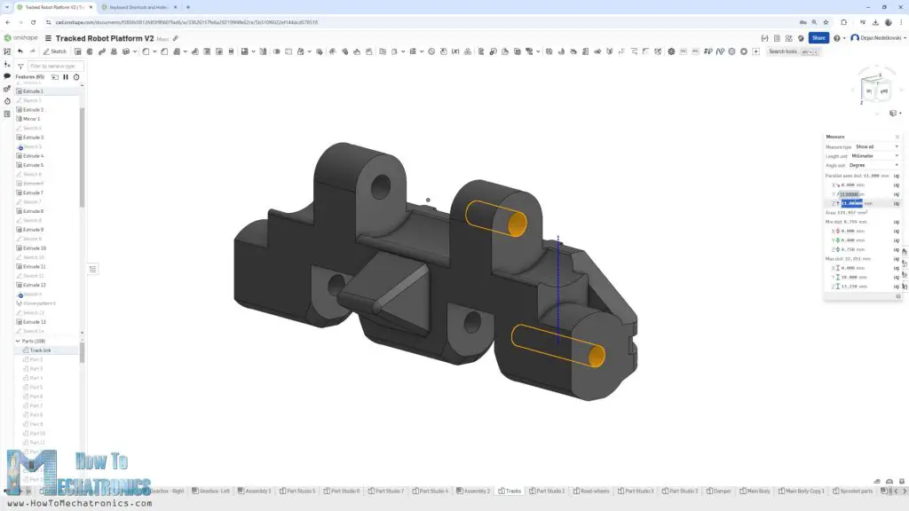
On top of that, when 3D printing, I wanted to avoid any use of support material for the part, which I actually managed to achieve with this design.
For connecting the track links to each other, I planned to use pins with 2mm diameter, so I dimensioned one side to be 2.1mm, to get tight fit, and the other side 2.4mm, to get loose fit so that the track links can rotate freely.
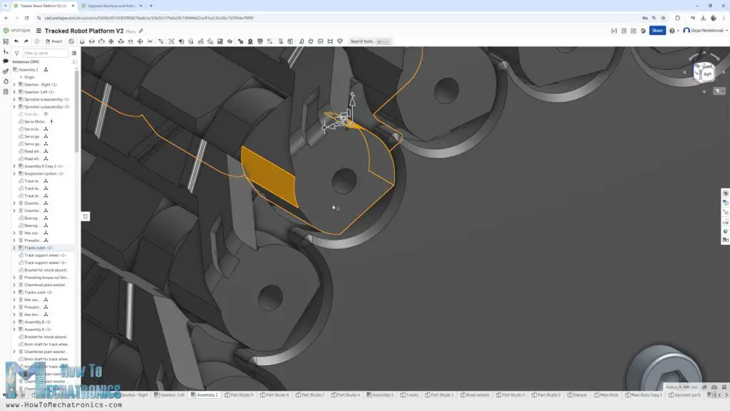
The sprocket teeth engage with the track links at the outer cylindrical shape. The track link cylinder has 4.4mm radius, while the sprocket has 4.9mm in order to have a loose fit to work properly.
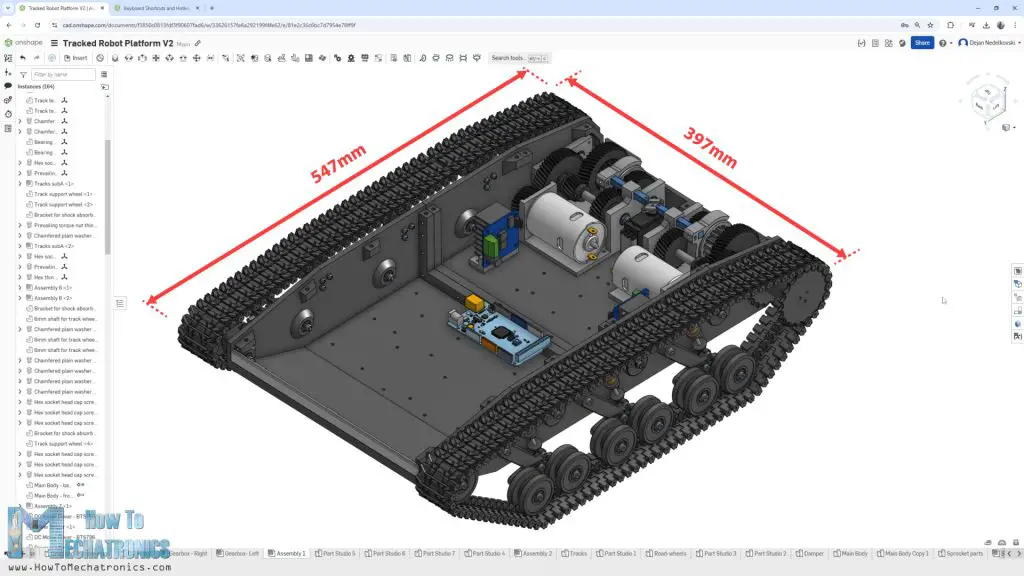
The main body where everything is connected, had to be big enough to fit the two gearboxes, and of course, to have space for the electronics and the battery. All this resulted the tank overall dimensions to be 547x397mm. That’s fairly big, bigger than the usual 3D printer’s bed, so therefore I divided the big parts into two sections, so we can print them on a 300mm bed 3D Printer. Please note that if you want to print it on a smaller 3D printer with 220mm, the model has to be divided into 4 sections. I will also provide that version in the 3D files.
For assembling the tank, we need various M3 and M4 bolts and nuts, as well as some threaded inserts and bearings. You can find a complete list of all the components needed for this project below. Of course, you can also find the 3D model and the STL files needed for 3D printing.
3D Model and STL Download Files
You can view the 3D model of this RC tank directly on your web-browser with Onshape.
You can get the 3D model of this RC tank/ robot platform , as well as the STL files for 3D Printing from Cults3D.
3D Printing
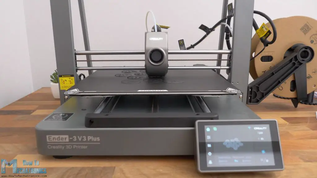
I used my Creality Ender-3 V3 Plus 3D printer for printing most of the parts for this tank.
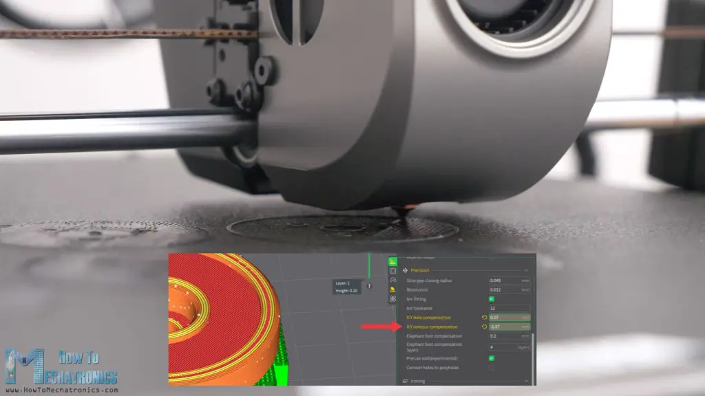
When 3D printing, it’s important to use the Horizonal Expansion feature, or now in the new Creality Print slicer that I used, it’s called X-Y contour compensation. If we leave these settings by default, the prints outer dimensions as well as the holes are usually smaller than the original model and we might have problem assembling them.
In the Creality Print slicer I used a value of –0.07 for the X-Y contour compensation, and plus 0.07 for the X-Y hole compensations feature. Of course, you should do some test prints to see what values will give you the best results on your 3D Printer.
For 3D Printing the track links, I used rafts as build plate adhesion, because their base contact surface with the bed plate is a bit small and might not stick well if the bed adhesion on your printer is not that good.
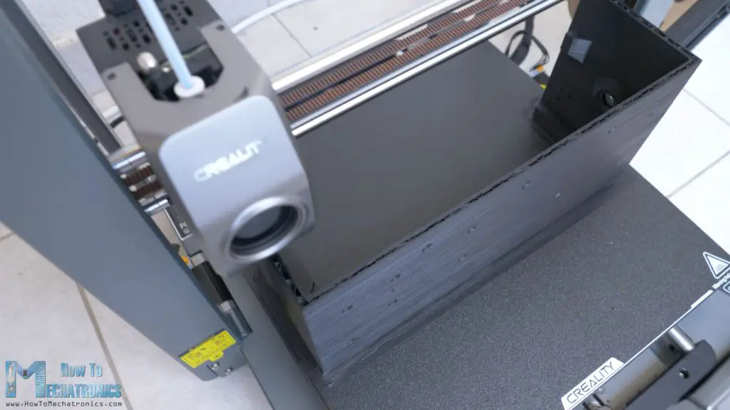
The Creality Ender-3 V3 Plus has a build plate of 300x300mm, so I could print the main body of the tank in two parts. Even in two sections, the parts are still quite big, and push the 3D printer to its limit. But the Creality Ender-3 V3 Plus managed to handle it and it did a great job printing these big parts.
I can recommend this 3D printer to anyone looking for a large volume and fast 3D printer. It a CoreXZ 3D Printer that can reach speeds of up to 600mm/s and with its sturdy frame it provides really good printing quality. Shout-out to Creality for providing me this 3D Printer.
Check out the Creality Ender-3 V3 Plus – USA store: https://shrsl.com/4rtkk ; EU store: http://shrsl.com/4rtkm ; Amazon: https://amzn.to/3VjEoRH
Assembling RC Tank
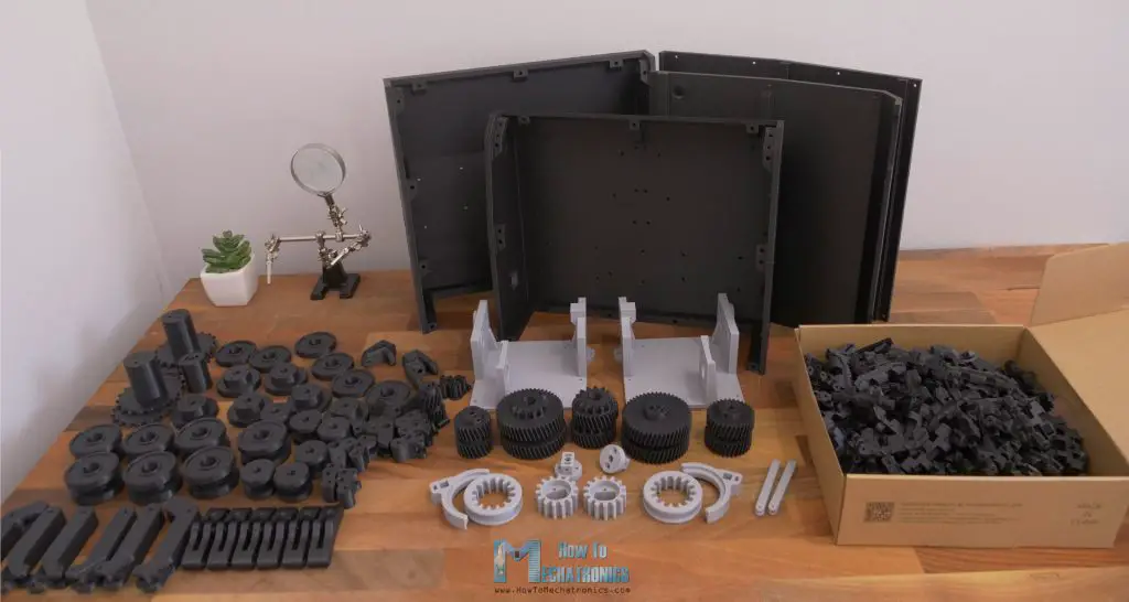
Here are all of the 3D printed parts, so we can start assembling the tank. To be honest, there is so much 3D printing. It takes like several days to print everything, and not just time, but we also need several spools of filament.
For the track links alone, because there are 214 track links total, we need around 500g and 30 hours of 3D printing. The main body of the tank needs around 1kg of filament, if divided in two sections like here, 500g and around 12 to 18 hours for each section. Also, many of the parts need to be 3D printed with support, so we need to do spend some time cleaning.
BOM
Here’s a list of components needed for assembling this RC tank project. The list for the electronics components can be found below in the circuit diagram section of the article.
| Component | Quantity | Purchase Links |
|---|---|---|
| RC Shock Absorbers | 8 | Amazon | AliExpress |
| Ball Bearing 686 – 6x13x5mm | 18 | Amazon | AliExpress |
| Ball Bearings 624 – 4x13x5mm | 44 | Amazon | AliExpress |
| Ball Bearing 684 4x9x4mm | 6 | Amazon | AliExpress |
| M6 Threaded Rod | 300mm | Amazon | AliExpress |
| M6 Lock-nut | 4 | Amazon | AliExpress |
| M3 Threaded Inserts | ~20 | Amazon | AliExpress |
| M3 Grub Screw | ~30 | Amazon | AliExpress |
| M3 and M4 bolts and nuts | To be specified | Amazon | AliExpress |
| 2mm Welding Rod | ~12m | Amazon | AliExpress |
| M3 and M4 bolts and nuts | See list below | Amazon | AliExpress |
| Bolts | Nuts |
|---|---|
| M3x8mm – 10 M3x10mm – 10 M3x16mm – 20 M3x20mm – 10 M3x25mm – 10 M3x30mm – 10 M3x16mm countersunk – 20 M4x16mm – 10 M4x35mm – 20 M4x40mm – 20 M5x40mm – 2 | M3 Lock-nut – 50 M4 Lock-nut – 40 M5 nut – 6 |
Disclosure: These are affiliate links. As an Amazon Associate I earn from qualifying purchases.
Electronics – RC Tank Circuit Diagram
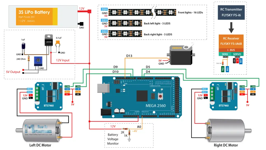
let’s take a look at the electronics for the RC tank and explain how it works. The brain of this RC tank is an ATmega2560 microcontroller-based board.
You can get the components needed for this project from the links below:
| Component | Quantity | Purchase Links |
|---|---|---|
| DC Motor 895 – 12V 200W 3000RPM | 2 | Amazon | AliExpress |
| BTS7960 DC Motor Driver | 2 | Amazon | AliExpress |
| Servo Motor | 1 | Amazon | AliExpress |
| ATmega2560 – Arduino Mega Board | 1 | Amazon | AliExpress |
| 3S LiPo Battery – minimum 3000mAh | 1 | Amazon | AliExpress |
| LiPo Battery Connectors | 1 | Amazon | AliExpress |
| Flysky FS-i6X – RC Transmitter and FS-iA6B Receiver | 1 | Amazon | AliExpress |
| WS2812b Addressable LED Strip | 1m | Amazon | AliExpress |
| LM350 Voltage Regulator | 1 | Amazon | AliExpress |
| Trimmer Pot – 5k | 1 | Amazon | AliExpress |
| Terminal Block Connector | 4 | Amazon | AliExpress |
| Wires ~20AWG | ~3m | Amazon | AliExpress |
| Rocker Switch | 1 | Amazon | AliExpress |
| Resistors – 1k x1 – 2k x1 – 240 x1 | Amazon | AliExpress | |
| Capacitors – 0.1uF x1 – 1uF x1 – 400uF x1 | Amazon | AliExpress |
Disclosure: These are affiliate links. As an Amazon Associate I earn from qualifying purchases.
Custom PCB Design
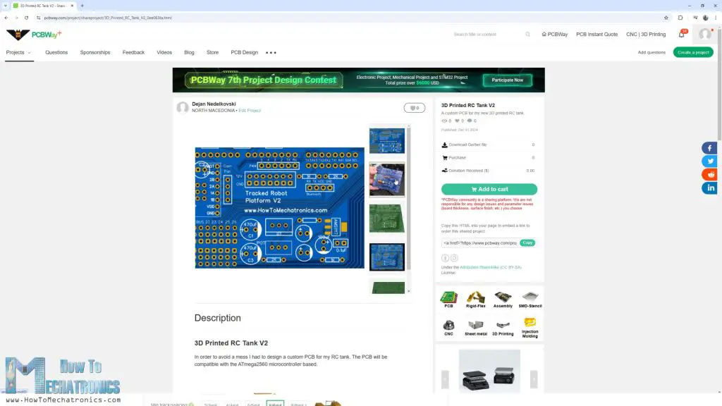
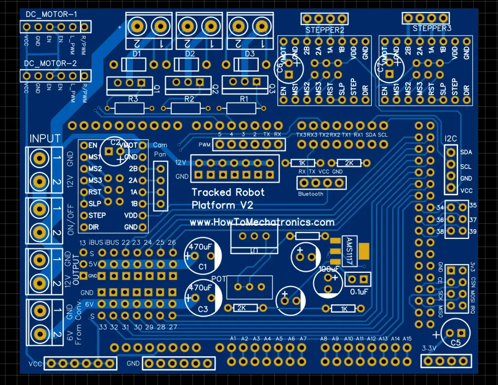
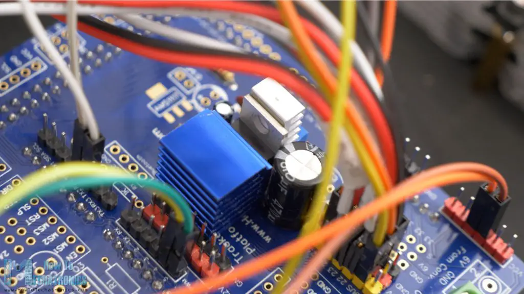
In order to keep the electronics components organized, I designed a custom PCB for the RC tank. The PCB will be compatible with the ATmega2560 microcontroller-based board to be directly mounted on top of it.
I ordered the PCB from PCBWay. Here we can simply upload the Gerber file, choose the properties of our PCB, and order it at a reasonable price.
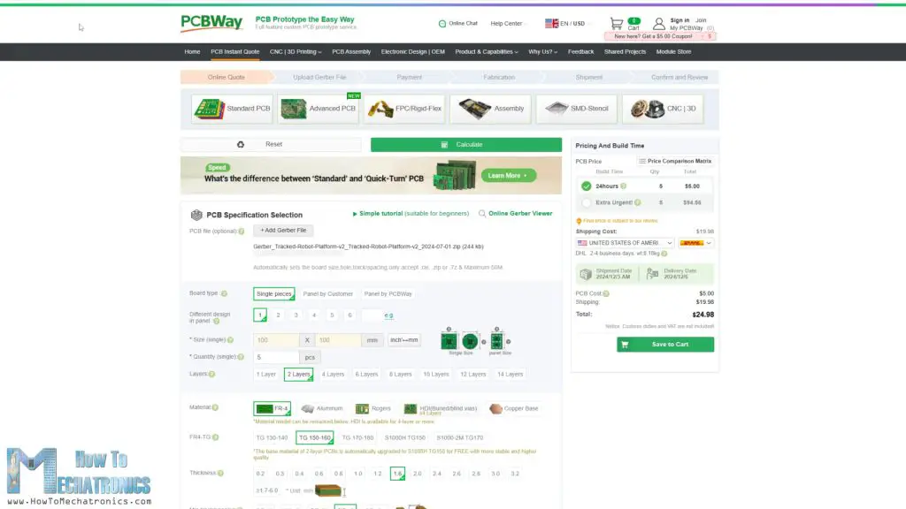
I didn’t change any of the default properties except for the PCB color which I chose to be blue. You can find and download the Gerber from the PCBWay projects sharing community through which you can also directly order the PCB.
Finishing RC Tank Assembly
In this section I will explain how to connect everything together and complete this RC tank.
This section is still under construction.
Programming the RC Tank – Arduino Code
In this section I will explain how the Arduino code behind the RC tank works. Here you can download the code:
Code overview
So, using the IBusBM library we read incoming data from the RC Transmitter.
// Reading the data comming from the RC Transmitter
  IBus.loop();
  ch0 = IBus.readChannel(0); // ch0 - left and right;
  ch1 = IBus.readChannel(1); // ch1 - forward and backward;

  ch6 = IBus.readChannel(6); // ch6 - Gear shifter
  ch7 = IBus.readChannel(7); // ch7 - Police light strobe effect
  ch8 = IBus.readChannel(8); // ch8 - All white LEDs
  ch9 = IBus.readChannel(9); // ch9 - Left and Right white LEDsCode language: JavaScript (javascript)
The right joystick, channels 0 and 1 are used for controlling the motion of the tank, the left rocker switch, or channel 6, for controlling the servo for shifting the gears, and the other three rocker switches for controlling the LEDs.
We convert the incoming data into values suitable for PWM control of the DC motors, which is from 0 to 255.
// convert the incoming date into suitable PWM value
  steeringValue = map(ch0, 1000, 2000, -205, 205); // 0 to 205 range because then I add +50 in order to avoid low PWM values as to motors won't start if so
  motorSpeed = map(ch1, 1000, 2000, -205, 205);
  motorSpeed = abs(motorSpeed);

  leftMotorSpeed = 50 + motorSpeed + steeringValue; // 50 + (0-205) + (0 - 205 ) =  50 - 255 so this range from 50 to 255 is used as PWM value
  rightMotorSpeed = 50 + motorSpeed - steeringValue;

  leftMotorSpeed = constrain(leftMotorSpeed, 0, 255); // constrain the PWM value from 0 to 255
  rightMotorSpeed = constrain(rightMotorSpeed, 0, 255);

  // if PWM is lower than 52, set PWM value to 0

  if (leftMotorSpeed < 52) {
    leftMotorSpeed = 0;
  }
  if (rightMotorSpeed < 52) {
    rightMotorSpeed = 0;
  }
Code language: JavaScript (javascript)
We send the PWM values to the drivers and the motors using the analogWrite() function appropriately.
// if right joystick goes up > move forward
  if (ch1 > 1510 && ch1 < 2000) {
    digitalWrite(M1_RPWM, 0);
    analogWrite(M1_LPWM, leftMotorSpeed);

    digitalWrite(M2_RPWM, 0);
    analogWrite(M2_LPWM, rightMotorSpeed);
  }
  // if right joystick goes down > move backward
  if (ch1 > 1000 && ch1 < 1490) {
    analogWrite(M1_RPWM, leftMotorSpeed);
    digitalWrite(M1_LPWM, 0);

    analogWrite(M2_RPWM, rightMotorSpeed);
    digitalWrite(M2_LPWM, 0);

  }

  // if right joystick is in the middle, don't move
  if (ch1 > 1490 && ch1 < 1510) {
    if (leftMotorSpeed < 50 && rightMotorSpeed < 50) {
      digitalWrite(M1_LPWM, 0);
      digitalWrite(M1_RPWM, 0);

      digitalWrite(M2_LPWM, 0);
      digitalWrite(M2_RPWM, 0);
    }
    // if right joystick move just left or right, without going up or down, move the tank left or right (in place)
    else if (ch0 < 1490 || ch0 > 1510) {
      analogWrite(M1_RPWM, rightMotorSpeed);
      analogWrite(M1_LPWM, leftMotorSpeed);

      analogWrite(M2_RPWM, leftMotorSpeed);
      analogWrite(M2_LPWM, rightMotorSpeed);


    }
  }Code language: JavaScript (javascript)
For the servo motor and shifting the gears, you should adjust the values according the servo you are using.
//======= Gear shift ====
  if (ch6 == 2000) {
    myservo.write(140);
  }
  if (ch6 == 1000) {
    myservo.write(40);
  }Code language: JavaScript (javascript)
As for the lights control, we check which rocker is switched, and according to it, tell light up each LED individually as needed.
//===== LIGHTS Control ===

  // Front and back lights LEDs control
  if (ch9 == 2000) {
    frontLeds[0] = CRGB (255, 255, 255);
    frontLeds[1] = CRGB (255, 255, 255);
    frontLeds[2] = CRGB (255, 255, 255);
    frontLeds[3] = CRGB (255, 255, 255);
    frontLeds[4] = CRGB (255, 255, 255);
    frontLeds[5] = CRGB (0, 0, 0);
    frontLeds[6] = CRGB (0, 0, 0);
    frontLeds[7] = CRGB (0, 0, 0);
    frontLeds[8] = CRGB (0, 0, 0);
    frontLeds[9] = CRGB (0, 0, 0);
    frontLeds[10] = CRGB (0, 0, 0);
    frontLeds[11] = CRGB (255, 255, 255);
    frontLeds[12] = CRGB (255, 255, 255);
    frontLeds[13] = CRGB (255, 255, 255);
    frontLeds[14] = CRGB (255, 255, 255);
    frontLeds[15] = CRGB (255, 255, 255);
    backLeftLeds[0] = CRGB ( 255, 0, 0);
    backLeftLeds[1] = CRGB ( 255, 0, 0);
    backLeftLeds[2] = CRGB ( 255, 0, 0);
    backRightLeds[0] = CRGB ( 255, 0, 0);
    backRightLeds[1] = CRGB ( 255, 0, 0);
    backRightLeds[2] = CRGB ( 255, 0, 0);
  }
  if (ch9 != ch9State) {
    if (ch9 == 1000) {
      FastLED.clear();
    }
    ch9State = ch9;
    FastLED.show();
  }

  // Front and back lights LEDs control
  if (ch8 == 1500) {
    frontLeds[0] = CRGB (255, 255, 255);
    frontLeds[1] = CRGB (255, 255, 255);
    frontLeds[2] = CRGB (255, 255, 255);
    frontLeds[3] = CRGB (255, 255, 255);
    frontLeds[4] = CRGB (255, 255, 255);
    frontLeds[5] = CRGB (255, 255, 255);
    frontLeds[6] = CRGB (255, 255, 255);
    frontLeds[7] = CRGB (255, 255, 255);
    frontLeds[8] = CRGB (255, 255, 255);
    frontLeds[9] = CRGB (255, 255, 255);
    frontLeds[10] = CRGB (255, 255, 255);
    frontLeds[11] = CRGB (255, 255, 255);
    frontLeds[12] = CRGB (255, 255, 255);
    frontLeds[13] = CRGB (255, 255, 255);
    frontLeds[14] = CRGB (255, 255, 255);
    frontLeds[15] = CRGB (255, 255, 255);
    backLeftLeds[0] = CRGB ( 255, 0, 0);
    backLeftLeds[1] = CRGB ( 255, 0, 0);
    backLeftLeds[2] = CRGB ( 255, 0, 0);
    backRightLeds[0] = CRGB ( 255, 0, 0);
    backRightLeds[1] = CRGB ( 255, 0, 0);
    backRightLeds[2] = CRGB ( 255, 0, 0);
  }

....and so on...Code language: JavaScript (javascript)
The Police lights strobe effect took me some time to code it, but it came out really cool.
Testing the 3D Printed Tank
Once we upload the code, we can power up the robot platform and the RC Transmitter for testing it out. On the transmitter display we can notice the LiPo battery voltage, as well as the receiver and the transmitter voltage.
Here we can also see how the gear shifting works in motion. With the left rocker switch we can switch the gears while the motors are running. It’s so actually, isn’t it.
With the other 3 rocker switches we control the tank lights. There are 4 different modes. Five LEDs on each side in white color, second mode all white LEDs on, third mode all white LEDs flashing and of course, the coolest mode, a police lights strobe effect. The tank can move with any of these light modes on.
Just a quick note here though. As the LEDs are powered through the 5V coming from the LM350 voltage regulator, it can get quite hot especially if all white LEDs mode is in use. Each LED consumes around 50-60mA of current for white color, so that’s almost around 1A of current.
The LM350 can handle up to 3A of current but it needs a big appropriate cooling for that purpose. I placed it in a wrong location on the custom PCB so that I couldn’t add suitable heatsink. I tried adding some small heatsinks from a stepper driver though.
They help a little bit but still if all white LEDs are on for a longer time the voltage regulator would overheat. But on all other modes, we are fine so I left the things as they are. In case we want to fix this issue, we could add a separate buck converter with 8A rated current. This buck converter can be powered from the 12V output terminal, and its 5 or 6V output that we set can go to the 6V terminal on the PCB and we can use the 6V rail for powering the LEDs.
Nevertheless, I hope you enjoyed this video and learned something new. Have fun building and driving this RC tank. Like I mentioned earlier, in future videos I plan to make some upgrades to this tank. I could add a robot arm on top of it, or maybe make a snow blower or something like that. So, stay tuned.
Hello. I am working on the Tank build now. 3D prints are coming along slowly. I was trying to order the rest of the supplies and found the AliExpress links are broken. Can they be fixed? I’m not in a hurry, so would rather get the parts cheap from AliExpress instead of fast from Amazon.
Looks like a fun build ahead of me. Thanks!
Hey, I hope you will have fun building it! I’m sorry I cannot always keep the links updated, as they very often change, especially on AliExpress. I have so many links from other projects as well. Please use the description of the item and try to find them on your own. Sorry about that once again.
Cheers
Is there any way I can get the tread wheels .stl? My folder does not include the track wheels. I have the road wheels, but no tread wheels.
Hey, I think you are talking about this file: “Tracks – Track link v8.stl”.
Hi…..any word on the programming code? Holding off buying the materials and building until that’s available.
Thanks
Hey, I’ve just updated the post to include the Arduino code.
Cheers!
Hi, Dejan. I have nearly assembled the V2 tank now, but I hit a problem and can’t figure out if I am doing something stupid. I ordered the V2 PCB as shared via the PCBWay community page. It looks slightly different from the version you show in the video, as the 240-ohm resistor has moved.
The bit I can’t work out is that the voltage regulator LM350 in U1 has both the input and output legs shorted together on the back side of the PCB, so the 5V rail is always permanently connected to the 12V. I am assuming the circuit should be similar to the V1 tank to allow you to adjust the output down to 5v as you show in the video – but I don’t see how that is possible on this PCB design?
Hey Rob, so sorry for the inconvenience. While modifying the PCB from v1 to v2 I have made that error. Here’s a close up of the error. Try to separate the 12V pin from the 5V by making a cut with utility knife or something like that.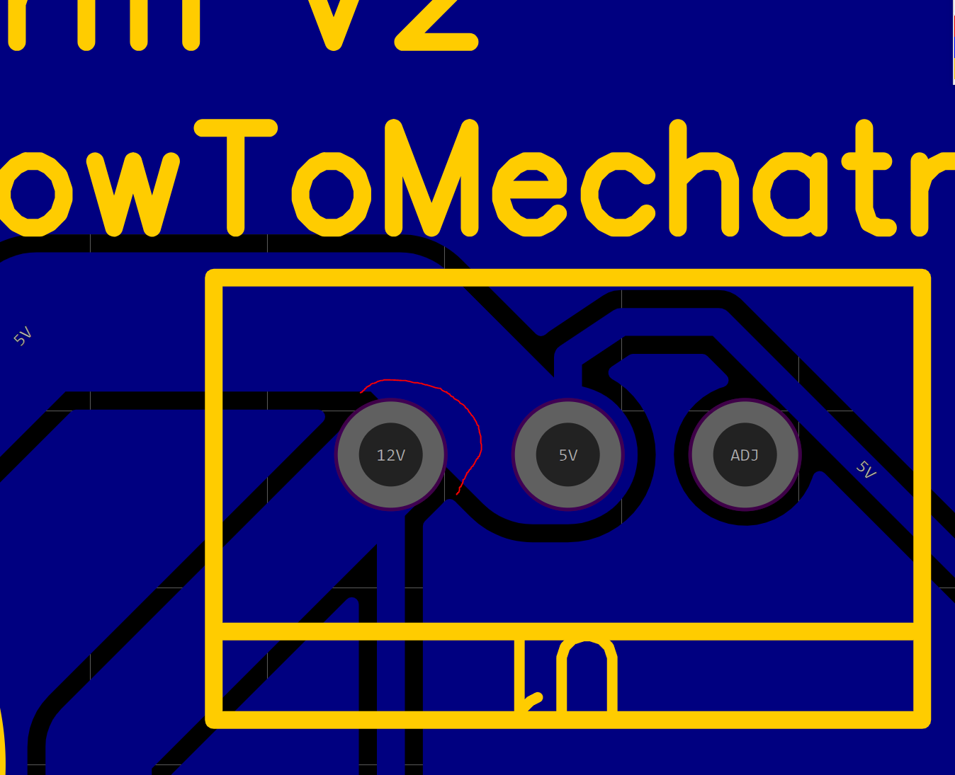
Of course, I will now update the PCB Gerber files to get rid of this problem.
Good evening and congratulations on the project.
Why do you specify M6 threaded rod in the BOM if the gear holes are smaller? Plus in the video you said m4.
What is really needed?
Thank you
Hey, thanks! The M6 threaded rod is for the gearboxes shafts. In the video I said we need an M8 by mistake. The holes of the gears are 5.9mm, so that we have tight fit.
Hi, Dejan. Thanks for sharing this model. It looks awesome. I just bought the 3D plans and look forward to building them. I built the V1 tank a few months ago, and that was a lot of fun, too, but like you said, it was a bit underpowered for off-road stuff. I ended up with 260rpm motors to give it enough grunt for outdoor driving, but the V2 with the gears and powerful motors looks excellent. Thank you.