In this Arduino Project I will show you how you can make an awesome LED heart photo frame using Arduino. You can watch the following video or read the written article below for more details.
At first glance it looks like an ordinary photo frame but once you click the switch on the back side it turns into extraordinary photo frame. Building this Arduino Project is very fun and it can be a perfect Valentine’s, Birthday or Anniversary present for your loved ones. So let’s get started building
Photo Frame Preparation
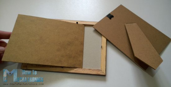
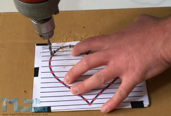
First we need a simple 18 x 13 cm photo frame and a fiberboard cut to the size of the frame on which will make holes for inserting the LEDs. Then we need to draw and print a heart shape with 32 LEDs which will be used as a pattern. We will make the holes for the LEDs using a drill.
Once we are done drilling the holes, we will start inserting the LEDs. We need to insert all LEDs on the same side, with the Anode or the longer lead pointing outside so that we can bend them and later solder the Anodes of all LEDs together.
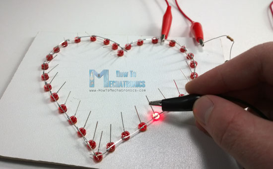
Once we have soldered all LEDs we should check whether all of them are working properly. For that we need to connect the positive 5 Volts VCC pin to the Anodes of the LEDs through a 220 Ohms resistor and using the Ground pin check each of LED whether it will light up.
Circuit Schematics
Here’s the circuit schematics of this project and you can find a complete list of components needed for this project below it . So we will use the Arduino Nano and the two TLC5940 ICs for controlling the LEDs. The TLC5940 is a 16-Channel LED Driver which provides PWM outputs. You can find more details how to connect and use this IC with the Arduino on my particular Arduino and TLC5940 Tutorial.
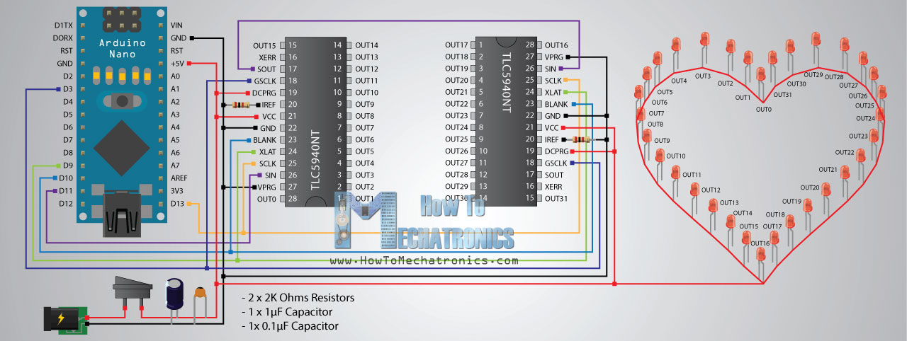
Components needed for this Arduino Project
You can get the components from any of the sites below:
- Arduino Nano……………………….. Amazon / Banggood / AliExpress
- Ultra Bright Red LEDs…………… Amazon / Banggood / AliExpress
- Switch………………………………….. Amazon / Banggood / AliExpress
- Power Jack…………………………… Amazon / Banggood / AliExpress
- DC 5V >1A Adapter……………….. Amazon / Banggood / AliExpress
- 2 x TLC5940 LED Drivers………. Amazon / AliExpress
- 2 x 2K Resistors ……………………..Amazon / Banggood / AliExpress
- 1uF & 0.1uF Capacitors ……………Amazon / Banggood / AliExpress
Disclosure: These are affiliate links. As an Amazon Associate I earn from qualifying purchases.
Assembling
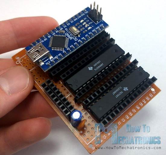
Here, first we will insert the IC sockets and the pin headers in place and solder them to the prototyping PCB so that we can attach the ICs and the Arduino Nano to them. We also need two additional pin headers with couple of slots for the power, or the 5 Volts VCC and the Ground pins, as well as two capacitors for decoupling.
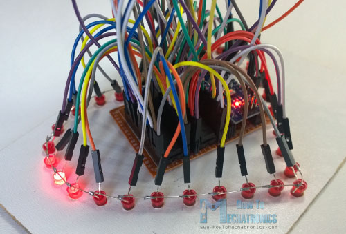
We need to be very careful when connecting the components because it can get very messy with that much wires if we connect something wrong. At this point we need to upload the Arduino code to make sure that we have connected everything properly.
Arduino Code
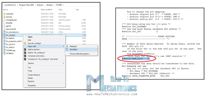
Let’s take a look at the Arduino code that I have made for this project. So we will use the TLC5940 Library made by Alex Leone. Once we download and install this library we need to modify the tlc_config.h file and change the value of the variable NUM_TLCS to the number of TLC5940 ICs connected in series and in our case that value is 2
With this done, now we can easily address all the LEDs from 0 to 31. At the beginning we also need to define some variables needed for the program. In the setup section we need to initiate the TLCs and in the loop section make the program. I organized the program into 9 different stages or light-shows of the LEDs using the switch statement.
For example, let’s take a look at the first stage. We generate random INT values from 0 to 31 and we use them as addresses for the LEDs. The function Tlc.set() is used for setting which LED we light up. The first parameter is the address of the LED, and the second parameter is the value of brightness of the LED or the PWM value which is from 0 to 4095. However, this won’t light up the LED right away, it just sets which LED will light up next when the Tlc.update() function will be executed. Using this “if” statement we activate the second stage after lighting up 8 random LEDs. Now let’s take a look at one more example, let’s say stage 3. Using this “for” loop we set all 32 LEDs to light up when the Tlc.update() function will be executed. After half a second delay using the Tlc.clear() function we clear and turn off all the LEDs. In similar way you can modify the code and add more light-shows on your own.
/*  LED Heart Photo Frame - Arduino Project
 *  Program made by Dejan Nedelkovski,
 *  www.HowToMechatronics.com
 */

/* TLC5940 Library by Alex Leone, https://code.google.com/archive/p/tlc5940arduino/
 *  You need to modify tlc_config.h located in the TLC5940 library
 *  and change the value of the variable NUM_TLCS to the numbers of TLC5940 ICs connected
 */

#include "Tlc5940.h"

int stage = 0;
int randomNumber;
int count = 0;
int brightness = 3500;
int brightUp = 50;
int dir=1;

void setup() {
  Tlc.init();
}

void loop() {

  switch(stage) {
    //-----Stage 1
    case 0:
      randomNumber = (int)random(0,31);
      Tlc.set(randomNumber,4095);
      delay(1500);
      Tlc.update();
      if(count >= 8) {
        stage = 1;
        count = 0;
      }
      else {
        ++count;
      }
    break;
    //-----Stage 2
    case 1:
      delay(75);
      for(int i=31;i>=0;i--) {
        Tlc.set(i,4095);
        delay(100);
        Tlc.update();
      }
      delay(500);
      Tlc.clear();
      Tlc.update();
      stage = 2;
      delay(500);
    break;
    //-----Stage 3
    case 2:
      for(int i=0;i<=31;i++) {
        Tlc.set(i,4095);
      }
      Tlc.update();
      delay(500);
      Tlc.clear();
      Tlc.update();
      delay(350);
      if(count > 6) {
        stage = 3;
        count = 0;
      }
      else {
        ++count;
      }
    break;
    //-----Stage 4
    case 3:
      for (int i=0;i<=15;i++) {
        Tlc.set(i,4095);
        Tlc.set(31-i,4095);
        Tlc.update();
        delay(70);
      }
      delay(50);
      for (int i=15;i>=0;i--) {
        Tlc.set(i,0);
        Tlc.set(31-i,0);
        Tlc.update();
        delay(70);
      }
      for (int i=15;i>=0;i--) {
        Tlc.set(i,4095);
        Tlc.set(31-i,4095);
        Tlc.update();
        delay(70);
      }
      for (int i=0;i<=15;i++) {
        Tlc.set(i,0);
        Tlc.set(31-i,0);
        Tlc.update();
        delay(70);
      }
      delay(50);

      Tlc.clear();
      Tlc.update();
      delay(100);
      if(count > 1) {
        stage = 4;
        count = 0;
      }
      else {
        ++count;
      }
    break;
    //-----Stage 5
    case 4:
      for (int i=15;i>=count;i--) {
        Tlc.set(32-i,4095);
        Tlc.update();
        delay(5);
        Tlc.set(32-i-1,0);
        Tlc.update();
        delay(5);
        Tlc.set(i,4095);
        Tlc.update();
        delay(5);
        Tlc.set(i+1,0);
        Tlc.update();
        delay(50);
      }
      if(count > 15) {
        Tlc.set(16,4095);
        Tlc.update();
        delay(2000);
        stage = 5;
        count = 0;
      }
      else {
        ++count;
      }
    break;
    //-----Stage 6
    case 5:
      for (int i=0;i<=31;i++) {
        Tlc.set(i,brightness);
        Tlc.update();
      }
      Tlc.update();
      brightness = brightness + brightUp;
      if (brightness>=3500) {
        brightUp=-50;
        ++count;
      }
      if (brightness<=150) {
        brightUp=50;
      }
      if(count > 6) {
        stage = 6;
        count = 0;
        brightness = 3500;
        Tlc.clear();
        Tlc.update();
      }
      delay(40);
    break;
    //-----Stage 7
    case 6:
      for (int i=0;i<=30;i+=2) {
        Tlc.set(i,4095);
        Tlc.set(i+1,0);
      }
      Tlc.update();
      delay(500);
      for (int i=0;i<=30;i+=2) {
        Tlc.set(i,0);
        Tlc.set(i+1,4095);
      }
      Tlc.update();
      delay(500);
      if(count > 20) {
        stage = 7;
        count = 0;
      }
      else {
        ++count;
      }
    break;
    //-----Stage 8
    case 7:
      for(int i=31;i>=16;i--) {
        Tlc.clear();
        Tlc.update();
        delay(2);
        Tlc.set(i,4095);
        Tlc.set(i+1,2000);
        Tlc.set(i+2,1000);
        Tlc.set(i+3,500);
        Tlc.set(i+4,300);
        Tlc.set(i+5,200);
        Tlc.set(i+6,100);
        Tlc.set(i+7,50);
        Tlc.set(i+8,0);

        Tlc.set(i-16,4095);
        Tlc.set(i-15,2000);
        Tlc.set(i-14,1000);
        Tlc.set(i-13,500);
        Tlc.set(i-12,300);
        Tlc.set(i-11,200);
        Tlc.set(i-10,100);
        Tlc.set(i+-9,50);
        Tlc.set(i-8,0);

        Tlc.update();
        delay(50);
      }
      if(count > 8) {
        for(int i=31;i>=0;i--) {
        Tlc.set(i,4095);
        Tlc.update();
        delay(50);
        }
        stage = 8;
        count = 0;
      }
      else {
        ++count;
      }
    break;
    //-----Stage 9
    case 8:
      for(int i=31;i>=0;i--) {
        Tlc.set(i+8,4095);
        Tlc.set(i+7,2000);
        Tlc.set(i+6,1000);
        Tlc.set(i+5,500);
        Tlc.set(i+4,300);
        Tlc.set(i+3,200);
        Tlc.set(i+2,100);
        Tlc.set(i+1,50);
        Tlc.set(i,0);
        Tlc.update();
        delay(50);
      }
      for(int i=31;i>=0;i--) {
        Tlc.set(i,4095);
        }
      Tlc.update();
      delay(10);
      if(count > 8) {
        delay(8000);
        Tlc.clear();
        Tlc.update();
        stage = 0;
        count = 0;
      }
      else {
        ++count;
      }
    break;

  }
}Code language: PHP (php)
Final Touch
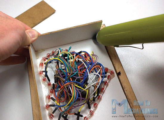
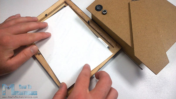
Once we are done with the programming and know that everything works well, we need to secure the LEDs to the fiberboard and I did that using a glue gun. Then we need to make a cover box for the electronics using a glue gun and 4 more pieces of fiberboard cut to size.
What’s left now is to connect the power lines coming from the switch and the power jack which are inserted in the fiberboard of the photo frame, add the photo, secure the whole box to the photo frame and we are done!
Here you can watch the complete demo video of the LED Heart Photo Frame.
Feel free to ask any question in the comments section below!
Great project, thanks. It works like a charm. My daughter loves the frame. She sleeps with lights on!
I made only a slight change, making the cover box on my 3D printer instead of fiberboard.
Once you finished, it is recommended to solder the wires to the leds for better contact.
I’m glad to hear that, thanks!
Hello, I occurred malfunction in my heart, need a hint where to find reason
One side of the heart is working, this one with pins 16-31. Yes I have changed variable: #define NUM_TLCS 2
Also I found out that TLC5940 responsible of heart that is not working got extremely hot
You might have connected something wrong, or simply the TLC5940 has failed.
Nice project and wonderful website ! I’ve made the heart for my girlfriend, she liked it alot.
Nice to hear this, thanks!