This was my Mechatronics Final Year Project at the Faculty of Mechanical Engineering in Skopje. It objective was to develop a device that will enable interaction of real arm movements with 3D computer models. I integrated three different fields in one device, t.e. mechanical, electrical and computer engineering:
- Solidworks to design the 3D model that represent the movements of the arm.
- Arduino Mega 2560 card for connecting the real world with the computer.
- MATLAB / Simulink to program the control of the 3D model
In the next video you can see a presentation of the project. This is its content:
- An Introduction. Here I briefly talk about the Mechatronics as a field of study which enabled me to develop this kind of a device.
- The Arduino Mega 2560. Some basic features of this Arduino Board which I used in this project.
- 3D Models in Simulink Environment. How to transfer 3D Model from Solidworks to Matlab / Simulink using the SimMechanics Link.
- Development of the device. Here I talko about the components that I used to build the device and how they work, as well as the Simulink Model, the program that is running on the Arduino Board and enables the interaction between the real world and the computer
- You can watch the following video or read the written tutorial below.
Building the device
Parts used in this project
- Arduino Mega 2560
- 3-Axis Accelerometer
- Linear Potentiometer x5

The accelerometer is used for tracking the orientation of the arm. As the arm moves, the values from the X, Y and Z axis from the accelerometer change and are being read in the Analog Inputs of the Arduino Board. According to them the 3D Model moves as well.
The potentiometers are used for tracking the position of the fingers. I attached a spring (pen spring) to each of the potentiometer. The spring holds the potentiometer slider at a certain position and as the fingers move the slider is being pulled and the resistance of the potentiometer is change. That values are being read in the Analog Inputs of the Arduino Board and according to them the 3D Model’s fingers moves as well.
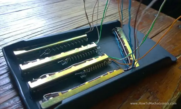
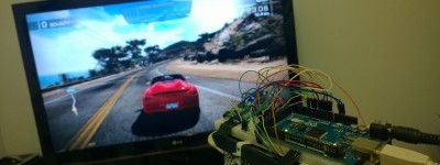
I used a plastic cover from a calculator as a base on which i attached the five potentiometrs. On top of them I put the Breadboard on which i secured the Arduino Board and the Accelerometer using a tape. On the picture below you can see the final appearance of the device.

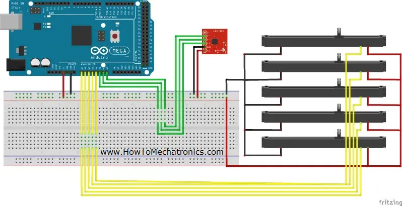
Circuit schematic of the device
The 3D Model
The 3D Model is a representation of a human arm. First, I modeled it using Solidworks and then I transferred it into Matlab / Simulink using the SimMechanicsLink from Matworks.


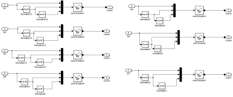
The MATLAB / Simulink Model
Before building the Simulink model, first I had to install the Arduino IO Package which consists the Simulink library for communication with the Arduino board. Also using the Arduino IDE i had to upload the code to the Arduino board that comes with the package to enable the Simulink library. Here I would highly recommend my Tutorial for Matlab and Arduino IO Package so that you can understand the working principle and see the code.

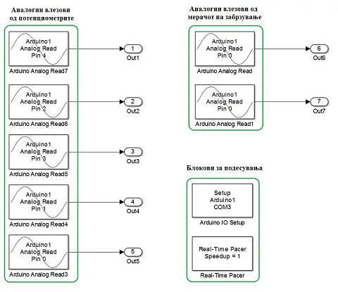
I organized my Simulink model into six subsystems:
- Arduino analog inputs blocks for the values from the accelerometer and the potentiometers
- Correction of the analog reads according to my needs
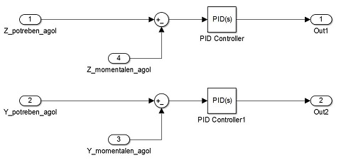
- PID control for getting smoother movements
- Joint Actuators blocks for driving the joints of the 3D model
- The 3D Model which was automatically generated using the SimMechanicsLink
- Joint sensor block for tracking the position the 3D model
You can Download the Simulink Model here:
Check my Extension of this Project.
I reprogrammed the Arduino Glove to work as a Game Controller.
what kind of potentiometer you used? and how many kilohms?
I used 10k potentiometers, but it doesn’t really matter, you could any value for it.
Hello, Dejan nice project.
what is the value of linear potentiometers?
I think it was 1K, but it doesn’t matter much, anything from 1K to 100k could do the job.
Excellent work! I want to make one too! Could you share more code and other details about this project with us?
Thanks. That’s all I have for this project.
I love this tutorial very much! I’d like to make one by myself. But I can not find the arduino code in this tutorial and how to use the SimMechanicsLink ? Could you help me out? Really appreciate!
The Arduino code comes with the Arduino IO Package and I have an example tutorial how to use the SimMechanicsLink here on the website. However, take a note at the version of your Matlab, because the latest versions don’t work with this Arduino IO Package, they have made a different one.
hi dejan
that very good project i did not understand how you linked to 3d animation ,because i think i don’t the mat lab so can please put a link where i can learn this integration of all the three things.so we can make some different thing
Thanks. Well there are already few tutorials related to this Project on my website.
Hello , Dejan!
What you’ve done is great! Congratulations! I got the idea to follow the rotary chassis , boom, arm and bucket of the excavator and always know how much have to dig. Much like your project. I’m curios how accurately can measure angles between components with combined accelerometer an gyro sensors. The rest is mathematics.
Greetings for best tutorials that you have shown here ! Keep going!
Hi there,
Well the gyro tends to drift and make errors. There are different filters that can reduce these errors but they could be complicated to be implemented.
So, a project like that would work for sure, although the mathematics would be complicated and as for the accuracy I could say anything specific.
Cheers!
great job, really it has helped me a lot.
Thanks, nice to hear that!
I am trying to build your system out of curiosity, with your help, the solidwork model now works, but, I am facing error when I run the simulink model in Matlab 2015. They show a algebraic loop error inside the PID controller. How did you get past this error? How can I do proper simulink rebuild? Awaiting your help. Thanks.
In the Simulink model you provided, how can I connect the imported xml model from the Solidworks file and the arduino hardware?
I would be highly grateful if you help me out.
Thanks
Check my other video tutorial for this one, Solidwroks and Matlab / Similink similation, you might find useful information.
Awesome bruh!! 🙂
WOW.You are perfet my friend,PERFECT! I realy like the way you do things,BRAVO!
just one question: can it work for the other 3d models like a MAYA or 3D MAX model? if the answer is yes, can you guid me about it?
thanks.
Thanks! Well it can work if you can transfer the model into Matlab/ Simulink.
Great Work, very interesting. The 3D Arm model you have uploaded here shows rebuild errors in Solidworks 2016. Is it possible to upload the file again?
Thanks! Yea it gives those errors because it is a .step file. Nevertheless, now I uploaded the Solidworks files as well.
Thank you very much. You are truly awesome for being so helpful to people all around the world.
hai…great work you have there…I’m wahid from malaysia..I’m doing my final year project this year..I want to ask, is it possible make the GUI for 5 axis robotic arms using the way you create yours?if it is possible, can you teach me how to do the integration between all the software?
Well yes it is possible but I can’t see how I can help you. That project would require quite big and time consuming.
awesome project ^^ plz where can i find the code source of arduino thxx 😉
Thanks. Well the code is from Matworks Arduino IO Package. Check my Arduino and Matlab Tutorial, you should find more details about that in that post.
BROTHER YOU HELPS ME ALOT THANKS DUDE…
Can I translate it to Turkish to make it benefical for people who cant speak english.
Well all my projects and tutorials are my original work on which I have put enormous amount of time and effort. All the photos, videos and illustrations are copyrighted. Just translating them to your language would be the same as copying them which is not allowed.
If you want to do that, you should rebuild (recreate) them on your own, with your own content (photos, videos, illustrations, text).
Thanks for understanding!
First thing you are doing great projects. the second and most valuable thing is you are sharing this information with public. I really appreciate that..
Thanks!
Can you give me full instruction please…. Or give me some link that i can learn an do this project…. Thanks….
Good project bro… I just like to know what sensor you use in this project…? Can you give the code you use for this..? I like to make it… If you help me, the will be so kind… Thanks for your post….
I’m using the code from the Arduino IO Package from Matwork/ Matlab. Check my Arduino and Matlab Tutorial in order to see how it works.
What sensor you use for this…?
Amazing bro. you have done great work.I’m mechatronics engineer and i also want make this project ,can you please share the arduino code.
i am mechatronics engineer bro. and i want to make this project,please share the code of arduino….
The Arduino code is the code from IO Library Package from Matworks/ Matlab.
Ammazing bro..
can i use arduino atmega328p instead of Arduino Mega 2560?
Thanks! Yes of course you can use that one or any other as well.
Nyc bro.Its a fantastic project. U r a brilliant.i want to make this project as final year project.To what have u connected the pen spring ???
Thanks! Well they are connected on the sliders. One side is to the slider itself, and the other end to the one side of the housing of the slider.
Please how could we add a button to turn it ON and OFF.
BRO ,you are awesome ,you work hard and you give the information clear .simple
Thanks!
Hey Dejan, awesome work. I really liked your informative videos and I finally understand how I2C works, which I never able to grasp before 🙂 Thanks buddy.
Keep up the new projects and informative videos about how things work. You really teach in simply way by putting up examples as well. Thumbs up 🙂
Thanks! I’m glad to hear this.
Awesome work bro……hats off..
Thanks!
Very good project mate, Are you on Facebook? I have some queries.
Thanks!
You can find me on Facebook here: https://www.facebook.com/howtomechatronics
awesome project.keep it up ……………with more useful thoughts
Thanks!