In this Arduino and Matlab Tutorial we will learn how to control the Arduino Board using Matlab GUI (Graphic User Interface). We will make a Matlab GUI with two buttons for turning on and off a led and an axis for plotting the analog input from a photocell (light-dependent resistor).
This is a step by step video Tutorial which is easy to be followed. Also, below the video you can find what componends needed for this tutorial and the Source Codes of the Examples in the video.
Components needed for this tutorial
You can get the components from any of the sites below:
- Arduino Board …………………………… Amazon / Banggood / AliExpress
- Breadboard and Jump Wires ……… Amazon / Banggood / AliExpress
- LED …………………………………………… Amazon / Banggood / AliExpress
- 220 Ohm Resistor …………………….. Amazon / Banggood / AliExpress
- Photoresistor ……………………………… Amazon / Banggood / AliExpress
Disclosure: These are affiliate links. As an Amazon Associate I earn from qualifying purchases.
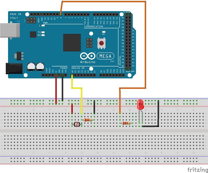
Circuit schematic
Download the Matlab files here:
Thank you for your tutorial. I have a question to ask.
Will this be possible with wireless connection (Bluetooth)?
For instance, I am getting sensor data from Arduino Uno using Bluetooth module(hc-05). I have seen a similar demo, https://www.youtube.com/watch?v=0AgscD5QM5s.
Could you possibly explain how I could achieve this, if you know how?
Thank you
Thank you for sharing your knowledge.
Could you show me your arduino code as well please?
or do you not need a seperate arduino code?
Thanks. Check my separate Arduino and Matlab tutorial so you can a better picture of how this communication works. The Arduino code comes with the Arduino IO package…
Hello !
Does the Aka ArduinoIO Package work well on Matlab 2015b ? Thanks in advance for your reply
Not sure about it, I haven’t tested it on that version.
very nice tutorial
hello
I want to connect ardiuno with matlap G u i to control on and off the led
I want to use 8 switch output and 4 digital input
any one can help me . thanks for all
Hello!
I am trying to do a proyect with the arduino. There are several Leds, where their time to be turned on should be selected by the user. I want to make a interface where the user enters the duration. Can you help me? How can I do this?
Thank you very much.
Ana
You can do that using the Arduino and the Processing IDE. It would be easier and it would look much better then using Matlab. Check out my tutorials for using Arduino and Processing IDE.
I made it. I also have a HCSR04 ultrasonic distance sensor.It only has digital inputs/outputs .It works well with the arduino IDE but there’s nothing defined for it in MATLAB . Can you find a way to plot the distance versus time variables?
Well you have to combine those two tutorials or code and make a code that will work you. I don’t have such a combination.
Good Day sir,
My project is similar to the tutorial shown above.
However, i am using a flowrate sensor with uses PWM digital pin.
so i made some changes to the code but there are errors which i am not able to solve.
changes i had made on matlab:
% — Executes on button press in read_button.
function read_button_Callback(hObject, eventdata, handles)
% hObject handle to read_button (see GCBO)
% eventdata reserved – to be defined in a future version of MATLAB
% handles structure with handles and user data (see GUIDATA)
global a k;
x=0;
for k=1:1:handles.xSamples
b = a.readDigitalPin(2);
x=[x,b];
plot(x,’LineWidth’,2); grid on;
axis([0 handles.xSamples 0 500 ]);
pause(0.01);
end
and the error message that popped up(when i typed a value in the edit_text gui):
Error while evaluating UIControl Callback
Undefined function or variable ‘data1’.
Error in iotestMatFlow>edit_text_samples_Callback (line 93)
handles.xSamples = str2double(hObject,data1);
Error in gui_mainfcn (line 95)
feval(varargin{:});
Error in iotestMatFlow (line 42)
gui_mainfcn(gui_State, varargin{:});
Error in @(hObject,eventdata)iotestMatFlow(‘edit_text_samples_Callback’,hObject,eventdata,guidata(hObject))
Error while evaluating UIControl Callback
>>
Really appreciate it if you can help!
Do you mind email me your arduino code for me to compare?
Thank you!
Well I’m not sure whether you are acquiring the data from the sensor correctly and why do you get error for the ‘data1’ variable as you haven;t changed anything there.
Really appreciate your time for looking through. Thank you so much!
is it possible for you to send me your arduino sketch for the tutorial?
Basically my codes are the at the top and bottom of the sketch.
The middle is the code from adioe.pde file.
Below is my arduino sketch:
volatile int NbTopsFan; //measuring the rising edges of the signal
int hallsensor = 2; //flow meter sensor connects to digial pin 2
int flow; //reading sensor value
//——————————————————————————-
/* Analog and Digital Input and Output Server for MATLAB */
/* Giampiero Campa, Copyright 2013 The MathWorks, Inc */
/* This file is meant to be used with the MATLAB arduino IO
package, however, it can be used from the IDE environment
(or any other serial terminal) by typing commands like:
0e0 : assigns digital pin #4 (e) as input
0f1 : assigns digital pin #5 (f) as output
0n1 : assigns digital pin #13 (n) as output
1c : reads digital pin #2 (c)
1e : reads digital pin #4 (e)
2n0 : sets digital pin #13 (n) low
2n1 : sets digital pin #13 (n) high
2f1 : sets digital pin #5 (f) high
2f0 : sets digital pin #5 (f) low
4j2 : sets digital pin #9 (j) to 50=ascii(2) over 255
4jz : sets digital pin #9 (j) to 122=ascii(z) over 255
3a : reads analog pin #0 (a)
3f : reads analog pin #5 (f)
R0 : sets analog reference to DEFAULT
R1 : sets analog reference to INTERNAL
R2 : sets analog reference to EXTERNAL
X3 : roundtrip example case returning the input (ascii(3))
99 : returns script type (0 adio.pde … 3 motor.pde ) */
/* define internal for the MEGA as 1.1V (as as for the 328) */
#if defined(__AVR_ATmega1280__) || defined(__AVR_ATmega2560__)
#define INTERNAL INTERNAL1V1
#endif
void setup()
{
pinMode(hallsensor, INPUT); //initializes digital pin 2 as an input
attachInterrupt(0, rpm, RISING); //and the interrupt is attached
Serial.begin(115200); //connection speed = 9600
}
void loop()
{
NbTopsFan = 0; //Set NbTops to 0 ready for calculations
sei(); //Enables interrupts
delay (1000); //Wait 1 second
cli(); //Disable interrupts
flow = (NbTopsFan * 60 / 7.5); //(Pulse frequency x 60) / 7.5Q, = flow rate
Serial.println(flow);
delay(1000);
//—————————————————————-
/* variables declaration and initialization */
static int s = -1; /* state */
static int pin = 13; /* generic pin number */
int val = 0; /* generic value read from serial */
int agv = 0; /* generic analog value */
int dgv = 0; /* generic digital value */
/* The following instruction constantly checks if anything
is available on the serial port. Nothing gets executed in
the loop if nothing is available to be read, but as soon
as anything becomes available, then the part coded after
the if statement (that is the real stuff) gets executed */
if (Serial.available() >0) {
/* whatever is available from the serial is read here */
val = Serial.read();
/* This part basically implements a state machine that
reads the serial port and makes just one transition
to a new state, depending on both the previous state
and the command that is read from the serial port.
Some commands need additional inputs from the serial
port, so they need 2 or 3 state transitions (each one
happening as soon as anything new is available from
the serial port) to be fully executed. After a command
is fully executed the state returns to its initial
value s=-1 */
switch (s) {
/* s=-1 means NOTHING RECEIVED YET ******************* */
case -1:
/* calculate next state */
if (val>47 && val40 && s90 && s!=340 && s!=400)) {
s=-1;
}
/* the break statements gets out of the switch-case, so
/* we go back and wait for new serial data */
break; /* s=-1 (initial state) taken care of */
/* s=0 or 1 means CHANGE PIN MODE */
case 0:
/* the second received value indicates the pin
from abs(‘c’)=99, pin 2, to abs(‘¦’)=166, pin 69 */
if (val>98 && val47 && val98 && val98 && val47 && val96 && val98 && val<167) {
pin=val-97; /* calculate pin */
s=41; /* next we will need to get value from serial */
}
else {
s=-1; /* if value is not a pin then return to -1 */
}
break; /* s=40 taken care of */
case 41:
/* the third received value indicates the analog value */
analogWrite(pin,val); /* perform Analog Output */
s=-1; /* we are done with AO so next state is -1 */
break; /* s=41 taken care of */
/* s=90 means Query Script Type:
(0 adio, 1 adioenc, 2 adiosrv, 3 motor) */
case 90:
if (val==57) {
/* if string sent is 99 send script type via serial */
Serial.println(0);
}
s=-1; /* we are done with this so next state is -1 */
break; /* s=90 taken care of */
/* s=340 or 341 means ANALOG REFERENCE *************** */
case 340:
/* the second received value indicates the reference,
which is encoded as is 0,1,2 for DEFAULT, INTERNAL
and EXTERNAL, respectively. Note that this function
is ignored for boards not featuring AVR or PIC32 */
#if defined(__AVR__) || defined(__PIC32MX__)
switch (val) {
case 48:
analogReference(DEFAULT);
break;
case 49:
analogReference(INTERNAL);
break;
case 50:
analogReference(EXTERNAL);
break;
default: /* unrecognized, no action */
break;
}
#endif
s=-1; /* we are done with this so next state is -1 */
break; /* s=341 taken care of */
/* s=400 roundtrip example function (returns the input)*/
case 400:
/* the second value (val) can really be anything here */
/* This is an auxiliary function that returns the ASCII
value of its first argument. It is provided as an
example for people that want to add their own code */
/* your own code goes here instead of the serial print */
Serial.println(val);
s=-1; /* we are done with the aux function so -1 */
break; /* s=400 taken care of */
/* ******* UNRECOGNIZED STATE, go back to s=-1 ******* */
default:
/* we should never get here but if we do it means we
are in an unexpected state so whatever is the second
received value we get out of here and back to s=-1 */
s=-1; /* go back to the initial state, break unneeded */
} /* end switch on state s */
} /* end if serial available */
} /* end loop statement */
void rpm() //This is the function that the interupt calls
{
NbTopsFan++; //This function measures the rising and falling edge of the
}
I’ve been using the default Arduino sketch, adioe.pde. I’m sorry I can’t help you with this one because I cannot make codes for every individual separately. The point of my tutorials is to provide as much knowledge as possible to all readers so they are able work out something new for their projects.
Hi Dejan,
Thanks for the code.
I have a doubt in the Read button function. What does the line x=[x,b]; implies. I am not able to understand it. Can you please help me?
It’s an array, which every next element has the value of the previous analog read “b”. Then this array is used for the plot.
This one might be helpful for better understanding: https://www.mathworks.com/help/matlab/ref/plot.html#btzptin
Great job, thank you for publishing and sharing your knowledge!
I amb carrying out a similar project with Arduino Mega and MATLAB, but I want to connect both components directly by means of an Ethernet cable using the UDP protocole. I’ve tried everything that I’ve seen googling it, but I can’t get the solution. Maybe you know how to do it if the procedure is similar to this one, do you? I don’t want to bore you with a copy-paste of my codes, I think they should be more or less ok.
Again, thank you for sharing it!
Thanks! Well I haven’t tried a procedure similar to what you ask, so I couldn’t answer your question.
that’s what we need in net special thanx dejan
great job, thank you
Thanks!
Undefined function ‘arduino’ for input arguments of type ‘char’.
Error in Example1>Example1_OpeningFcn (line 66)
a = arduino(‘COM10’);
Error in gui_mainfcn (line 221)
feval(gui_State.gui_OpeningFcn, gui_hFigure, [], guidata(gui_hFigure), varargin{:});
Error in Example1 (line 42)
gui_mainfcn(gui_State, varargin{:});
Try again to do exactly the same as described in the video. Also the version of your Matlab and the plugin could be the problem, as they have released new Arduino plugins for the the Matlab 2015.