In this article I will show you how you can make an Arduino Color Sorter. You can watch the following video or read the written article below.
Design
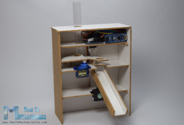
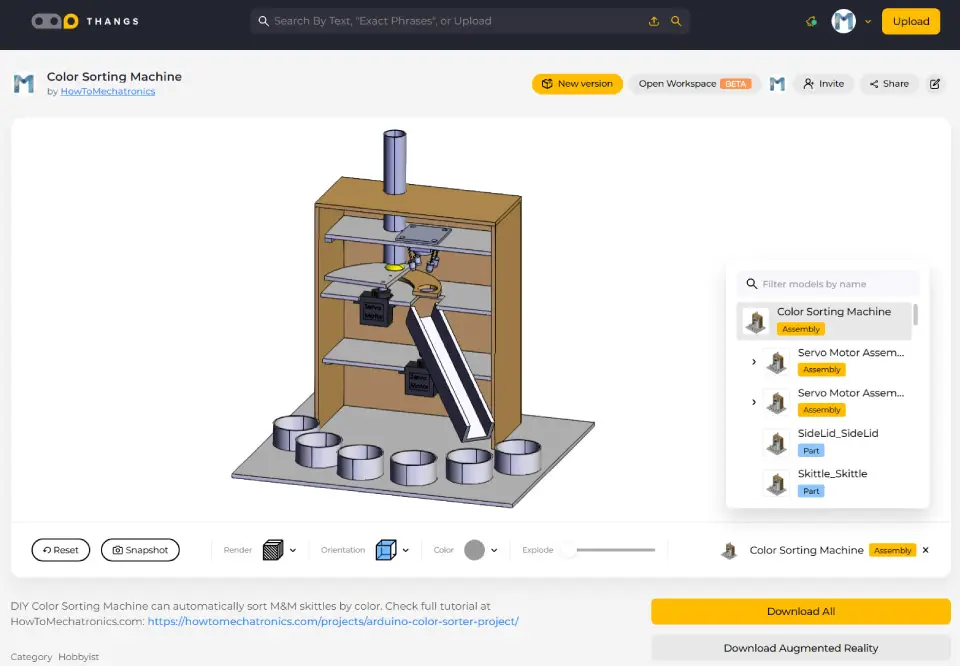
All we need for this Arduino project is one color sensor (TCS3200) and two hobbyist servo motors, which makes this project quite simple but yet very fun to build it. In the first place, using the Solidworks 3D modeling software I made the design of the color sorter and here’s its working principle:
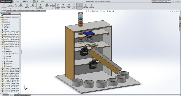
- Initially, the colored skittles which are held in the charger drop into the platform attached on the top servo motor.
- Then the servo motor rotates and brings the skittle to the color sensor which detects its color.
- After that the bottom servo motor rotates to the particular position and then the top servo motor rotates again till the skittle drop into the guide rail.
Here you can download the 3D model, as well as, the drawings with all dimensions needed for building this Arduino project.
You can find and download this 3D model, as well as explore it in your browser on Thangs.
Download the assembly 3D model at Thangs.
The following drawings can be used for laser cutting all the parts for the case:
Building the Arduino Color Sorter
The material that I used for this project is a 3 mm tick fiberboard. I redraw the parts on the fiberboard according to the drawings and using a small hand saw cut all the parts to size.
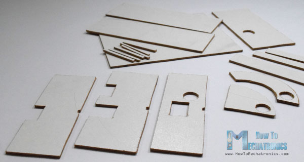
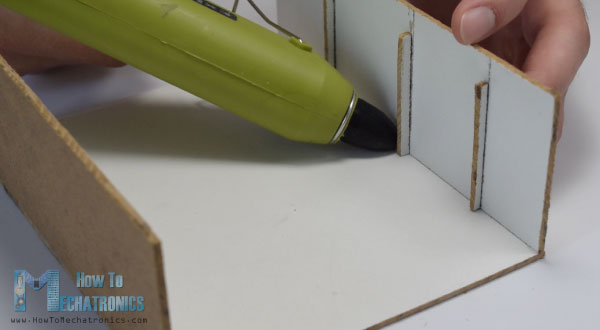
Once I got all the parts ready, I started assembling them. First I assembled the outer parts using a glue gun.
Then using all-purpose glue I glued the two servo motors on their platforms and attached them to the assembly.
After that again using a glue I attached the guide rail on the bottom servo motor as well as the support and the platform needed for the top servo motor.
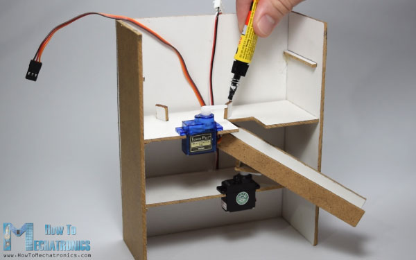
Next, I inserted a switch and a power jack for powering the Arduino with a 5V adapter and on the third platform I inserted the color sensor.
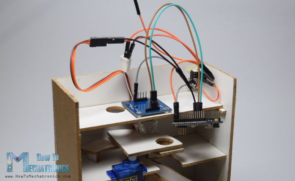
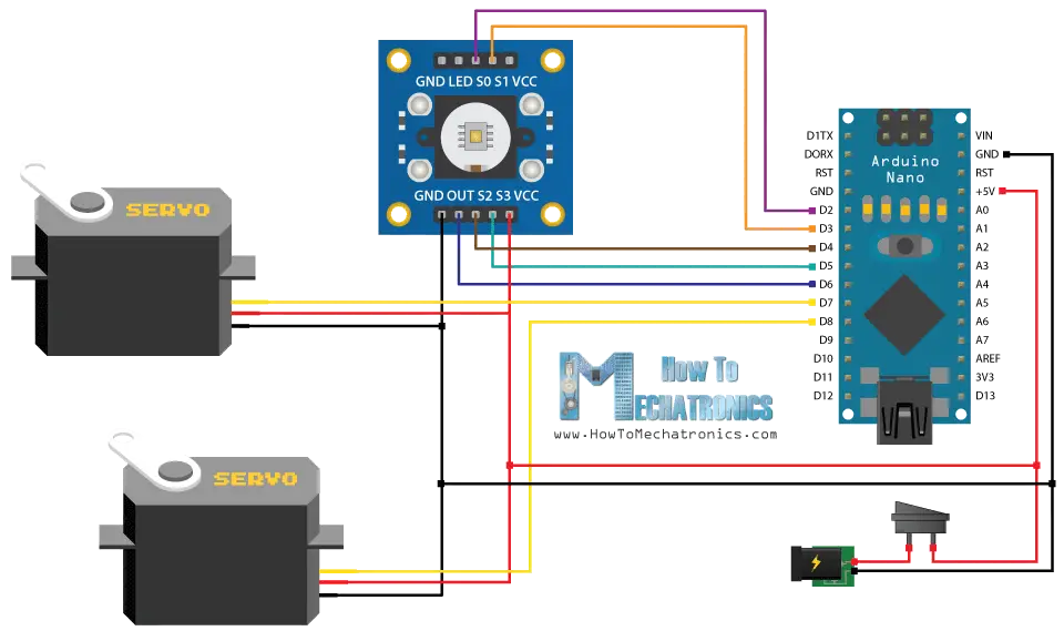
I connected the components together according to the following circuit schematics.
You can get the components needed for this Arduino Project from links below:
- TCS230 TCS3200 Color Sensor……. Amazon / Banggood / AliExpress
- Arduino Nano ……………………………. Amazon / Banggood / AliExpress
- Breadboard and Jump Wires ……… Amazon / Banggood / AliExpress
- Servo Motor ………………………………. Amazon / Banggood / AliExpress
- Switch………………………………….…….. Amazon / Banggood / AliExpress
- Power Jack…………………………….…… Amazon / Banggood / AliExpress
Disclosure: These are affiliate links. As an Amazon Associate I earn from qualifying purchases.
Arduino Color Sorter Source Code
At this point, first we need to program the Arduino and then finish the assembly. Here’s the Arduino Code:
/*     Arduino Project - Color Sorting Machine
 *
 *  by Dejan Nedelkovski, www.HowToMechatronics.com
 *
 */
#include <Servo.h>

#define S0 2
#define S1 3
#define S2 4
#define S3 5
#define sensorOut 6

Servo topServo;
Servo bottomServo;

int frequency = 0;
int color=0;

void setup() {
  pinMode(S0, OUTPUT);
  pinMode(S1, OUTPUT);
  pinMode(S2, OUTPUT);
  pinMode(S3, OUTPUT);
  pinMode(sensorOut, INPUT);

  // Setting frequency-scaling to 20%
  digitalWrite(S0, HIGH);
  digitalWrite(S1, LOW);

  topServo.attach(7);
  bottomServo.attach(8);

  Serial.begin(9600);
}

void loop() {

  topServo.write(115);
  delay(500);

  for(int i = 115; i > 65; i--) {
    topServo.write(i);
    delay(2);
  }
  delay(500);

  color = readColor();
  delay(10);

  switch (color) {
    case 1:
    bottomServo.write(50);
    break;

    case 2:
    bottomServo.write(75);
    break;

    case 3:
    bottomServo.write(100);
    break;

    case 4:
    bottomServo.write(125);
    break;

    case 5:
    bottomServo.write(150);
    break;

    case 6:
    bottomServo.write(175);
    break;

    case 0:
    break;
  }
  delay(300);

  for(int i = 65; i > 29; i--) {
    topServo.write(i);
    delay(2);
  }
  delay(200);

  for(int i = 29; i < 115; i++) {
    topServo.write(i);
    delay(2);
  }
  color=0;
}

// Custom Function - readColor()
int readColor() {
  // Setting red filtered photodiodes to be read
  digitalWrite(S2, LOW);
  digitalWrite(S3, LOW);
  // Reading the output frequency
  frequency = pulseIn(sensorOut, LOW);
  int R = frequency;
  // Printing the value on the serial monitor
  Serial.print("R= ");//printing name
  Serial.print(frequency);//printing RED color frequency
  Serial.print("  ");
  delay(50);

  // Setting Green filtered photodiodes to be read
  digitalWrite(S2, HIGH);
  digitalWrite(S3, HIGH);
  // Reading the output frequency
  frequency = pulseIn(sensorOut, LOW);
  int G = frequency;
  // Printing the value on the serial monitor
  Serial.print("G= ");//printing name
  Serial.print(frequency);//printing RED color frequency
  Serial.print("  ");
  delay(50);

  // Setting Blue filtered photodiodes to be read
  digitalWrite(S2, LOW);
  digitalWrite(S3, HIGH);
  // Reading the output frequency
  frequency = pulseIn(sensorOut, LOW);
  int B = frequency;
  // Printing the value on the serial monitor
  Serial.print("B= ");//printing name
  Serial.print(frequency);//printing RED color frequency
  Serial.println("  ");
  delay(50);

  if(R<45 & R>32 & G<65 & G>55){
    color = 1; // Red
  }
  if(G<55 & G>43 & B<47 &B>35){
    color = 2; // Orange
  }
  if(R<53 & R>40 & G<53 & G>40){
    color = 3; // Green
  }
  if(R<38 & R>24 & G<44 & G>30){
    color = 4; // Yellow
  }
  if(R<56 & R>46 & G<65 & G>55){
    color = 5; // Brown
  }
  if (G<58 & G>45 & B<40 &B>26){
    color = 6; // Blue
  }
  return color;
}Code language: PHP (php)
Description of the code:
So, we need to include the “Servo.h” library, define the pins to which the color sensor will be connected, create the servo objects and declare some variables needed for the program. In the setup section we need to define the pins as Outputs and Inputs, set the frequency-scaling for the color sensor, define the servo pins and start the serial communication for printing the results of the color read on the serial monitor.
In the loop section, our program starts with moving the top servo motor to the position of the skittle charger. Note that this value of 115 suits to my parts and my servo motor, so you should adjust this value as well as the following values for the servo motors according to your build.
Next using the “for” loop we will rotate and bring the skittle to the position of the color sensor. We are using a “for” loop so that we can control the speed of the rotation by changing the delay time in loop.
Next, after half a second delay, using the custom made function, readColor() we will read the color of the skittle. Here’s the code of the custom function. Using the four control pins and the frequency output pin of the color sensor we read color of the skittle. The sensor reads 3 different values for each skittle, Red, Green and Blue and according to these values we tell what the actual color is. For more details how the TCS3200 color sensor works you can check my previous detailed tutorial about it.
Here are the RGB values that I got from the sensor for each skittle. Note that these values can vary because the sensors isn’t always accurate. Therefore, using these “if” statements we allow the sensor an error of around +-5 of the tested value for the particular color. So for example if we have a Red skittle, the first “if” statement will be true and the variable “color” will get the value 1. So that’s what the readColor() custom function does and after that using a “switch-case” statement we rotate the bottom servo to the particular position. At the end we further rotate the top servo motor until the skittle drops into the guide rail and again send it back to the initial position so that the process can repeated.
Finishing the Design
After uploading the code I secured the Arduino Board using a glue gun.
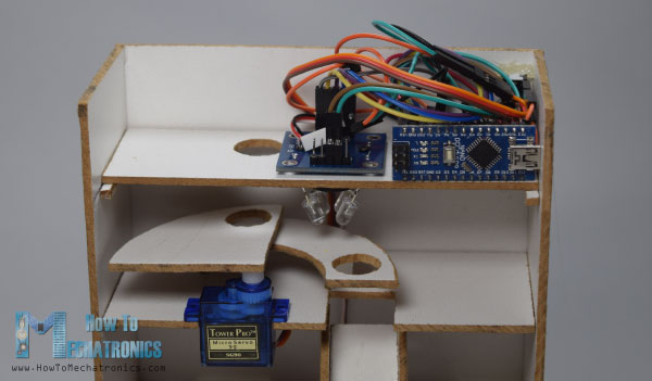
Then using a transparent plastic bottle I made the charger and together with the top part glued it to assembly and finished the project.
Feel free to ask any question in the comments section below.
Dejan, Made the sorter using 3D printer and having minor issues. Modified code for top servo location, easy. Colour sensor not real brilliant but changed the if statements to allow for fairly wide spread of readings. The problem I have is it all works well, till I connect the bottom servo, then it does strange things. Both servos jitter back and forth. Tried different servos, different UNO’s, different power supplies. Change the Uno pin from 8 to 9, no difference. Any ideas ?? Yes, double checked wiring !!
PS. Like your tutorial, it was easy to follow.
Hey, I’m not quite sure what could be the problem when connecting the bottom servo. So many people reported that they problem with the bottom servo. I didn’t have any problem. I would suggest powering the servos from separate, external power supply, not the Arduino 5V pin. Also make sure the if statements are set up correctly so everything works properly.
Also, try going step by step, with a simple code that will first move the top servo, then the bottom servo to check whether it’s the code or the servos the problem. Try external power supply for them, try other other available Arduino pins for both servos.
hello sir
great project
i hv made it everything is working alright but the senor is not giving consistent RGB readings they are not in a way by which i can decide any range
and if i give a big range red orange purple all are mixing up
plz sir do hv any trick for this im worried about it hv to submit in july really need ur help thank you
Hey, thanks! Well the problem is the sensor itself, it just not that stable and reliable. Try to use different environment light, try to add some more light to the sensor reading area with a simple light bulb or something.
thanks a lot, really helped me!
Good afternoon,
Congrats for the idea!! It’s amazing!
I was wondering if it becomes a problem to use a S3S2OUTVCC color sensor instead of the one you’ve mentioned before.
Thnks!
Sure, you could use a different color sensor, but it would need to be appropriately programmed.
What is the height of this design, approximately?
Around 30 cm. Of course, you could modify that.
hi, I can’t open the solidworks files.what is the version you used to make that drawings?
Hey, it’s version 2017.
Dejan,
I’ve built the color sorter, I’m new to Arduino and am having problems. My Bottom servo will not move. I have shown the sensor several different colors. I have tried a spare servo motor, I have checked and rechecked my jumpers and the wiring schematic. Also my top servo seems to be scaled incorrectly, as it does not swing far enough either direction to pick up a skittle and drop it down the chute.
Reading thru the comments, this seems to be a common issue not having the bottom servo work. Can you please offer some guidance? or troubleshooting tips?
How can I see the values the color sensor is seeing?
BTW Your site rocks!
Thank you! Well yea it’s true, many have problems with the bottom servo. What I can guess is that the color sensor is not reading the correct values. You need to test what values are you getting from the color sensor, and adjust the values in the if statements at the bottom of the code.
Another way to test whether the servo is working, is to manually set the “int color=0;” variable, which is at the top of the code, anything from 1 to 6, so the servo should move to any of those position. If this works, that’s the problem is definitely the values you are getting from the sensor doesn’t match the if statements at the bottom of the code.
Hi, I think it’s a very interesting project, I’m studying electronics, I’m going in the first year and I’d like to do a job similar to yours for educational purposes.
I would like to be able to quote your project, it does not bother you.
Thanks! Yes, it’s great project for studying electronics and sure, go ahead, I’m certain you will have fun building it.
hi. thanks for the tutorial. its really helpful. Sorry if the question is too dumb.
Is it possible to power the arduino, sensor, and the servo using only the usb port?
I plan to use powerbankk as its power supply. if it possible, how to do that and will the electric schematic remain the same?
Thankyou.
Thanks. The electric schematic would remain the same and you should be able to power the project with a powerbank.
Hi,
Nice project you’ve done.
Also the support you offer your fans is great!
I’m just staring off with arduino, and this is my first ‘real’ project.
About supplying power, can i put 7,4V of a Lipo battery on the Raw pin of the arduino?
And maybe you can recommend me some programming tuturials, i’ve only worked with function block diagrams in Codesys 2.3 in use with a PLC.
Thanks in advance.
Gijs
Thanks. You could use 7.4V for powering the Arduino but you need to connect this to the either the Power Jack or the Vin pin. Using this method the 7.4V would pass through the 5V regulator of the Arduino board, so the Arduino would work without a problem.
Hey you wouldn’t possibly have a sketch that runs just the servos?
my bottom servo motor not working. what i need to do? i also have recheck my connection.. but that is no wrong.
Maybe you don’t have enough power if you are using the Arduino for powering the two servos. Try using external power source.
Hello. I am using your project as a school robotics final. Your website is very helpful, but I was wondering how big the tube you used to feed the skittles through was. Is the material just a cheap plastic? Thank you.
Hey, I made the tube out of simple water or something bottle.
Is it normal if sometime the sorter will mix a green and orange skittles .
Yes, it’s normal as the color detector isn’t that much accurate.
good day sir,
amazing project right there. I have just one question – how do i change the direction of the top servo motor? I got the motion correct, just direction. I need to change it to clockwise from anti clockwise.
thank you
Well the servo motor can rotate 180 degrees, so it’s up to you to place/position the servo motor so that you can the desired motion or direction.
hi sir
I’m sorry if i can’t write in well
i wanna ask something, can this arduino with color sensor to read average color in 2 sec for “telling” what is this based on color
like a red color in apple, because apple not really red color. I think if we take an average value in few sec, this arduino can tell this an apple, ect
if you can help me please contact me, cause I’m interested from yours idea
Sure it can be used for such a purpose. But it depends what will you compare the red apples to. For example if you compare them to green apples it would be probably be easy to distinguish the colors.
that is i mean just read red apples or green
but, the next is
the output is countering the “apple” and the information output displayed on lcd
for example, i put the green and red apple in the pipes integrated with the sensor, automatically it will sort how many the green apples in the 1 round of sort and how many too in red apple
i really need help from you sir 😀
nice project…the dimensions are in mm i guess..i was confused with the scale 1:5 in the diagrams..
Hey man, i have a little (huge) problem, when i try to upload the program it says “`readColor` was not declared in this scope” i don´t know why it happens and i checked the whole program but it´s the same as this page´s.
I´m so bad with Arduino so i hope you can help me to solve it.
You have a typo in the code, you probably haven’t copied it properly.
Hello Dejan,
This is a really good project but I have a problem. One of the servomotors moves at the same directions repeatedly but the bottom servomotor doesn’t move at all. What should I do?
You are not getting the same values for the colors as mine, so you should adjust them.
Hello, I have one question – while trying to setup everything as explained here, I can’t get my sensor motor to rotate based on colour change. It simply stays non moving. Motor is fine, replacing it with working one yields same result. Do you have any hint as to what could be the issue? Thanks.
Hello, the problem is probably that the values you are getting from your color sensor doesn’t match with my values. First you must see what values you are getting from your color sensor for a particular color, and then adjust these values in the readColor() custom function, where the last “if” statements are.
Hey there.
I built the whole model and got the same exact pieces as you but… My TCS3200 has red leds on the board, not white ones.
Also, the values it reads are all around 15000 for each color (R, G or B).
Any idea on why this happens?
Hi there, well you probably have a different version of the module, but it should be a problem, you can make it work. You just have to adjust the values for each color in the “if” statements in the readColor() custom function.
Hello! How to manually adjust the sensor values to match the colors? Thanks for the answer 😀
ps great project!
Print the values you are getting into the Serial monitor and then adjust them in the readColor() custom function.
Hi,
For the if statements at the bottom of your code, why do you only use two of the colors (i.e.
if(R32 & G55){
color = 1; // Red
}) -> only red and green are used. Why don’t you use red, green, and blue in each of the statements?
Thanks,
Hi, that’s because the sensor outputs were not that precise and accurate and I was getting very similar values, close to each other, for each R, G and B. So in order to better separate, or recognize the colors I made the “if” statements in such a way to use only two colors for defining the colors I needed.
can i use SG90 9g servo motor for both positions?? by using thin(very light) plywood…!!!!!!
Yes sure, they would be fine.
thank you very much….i am doing this project as my major project
Hi, please help me, when I try to put blue item on the color sensor, it gives out green color 🙁
You must manually adjust the sensor values to match the real color.
how???? can i do that???
Hai sir.For this project we have to connect arduino board by usb and with power adapter or not.
You can use any of them.
Hi, and Thanks for the inspiration for my next project. Just waiting on the delivery of my TCS3200 sensor now.
While reading and understanding your code I’ve spotted 2 typo errors (which don’t affect the functionality, of course, just my initial understanding of how it works). In lines 116 and 128 you repeat the comment “// printing RED color frequency” but those lines should say GREEN and BLUE respectively.
Thanks again for such a clear and simple approach.
Hi, Mr. Dejan
Nice project
I try same project and copy your code into my Mega2560. I have following the schematic diagram. But, my bottom servo not working. Whats wrong?
Thank you
Thanks. What kind of servo motor are you using? Double check your connection.
Sir how to give power supply to Arduino?? Can i connect it directly with 5v battery or i have to use a Arduino power supply module..please help or give a link of power supply to buy online.
Well if you have a 5V battery of adapter you can connect it directly to the 5V pin of the Arduino.
Hi. I followed your instructions and code but the two servos are not running. what might be the reason?
It can be anything. Can you try to be more specific. Also double check your connection.
hello , i´ve tried to replicate your project but my servos just wont move, and i´ve been using different power supplies even a 5v-2A power supply but it doesnt work,
could you tell me what power supply did you use to power your electronics???
any advice you can give me??’
What kind of motor are us using? Did your try to swap the two motors? Is it working that way?
hi..İt is great project! 🙁 I did this but bottom servo not working.
I think the output of colour sensor is not connected with arduino, check it once @Mustafa
i am done with model and the project is working well. just the color sensor is getting confuse :/
i have set the frequencies as per my color sensor . but still the bottom servo rotates at different angle for same color 🙁
what should i do ?
Well the sensor isn’t stable and makes errors when reading. Plus its readings depends on several factors like obviously the color you are reading but also the ambient lighting as well. So if it’s darker you will probably get different readings compared if you are using the same color object and test it on daylight.
In order to make it working you must test the color readings for each object and according to your readings adjust the R, G and B that are found values at the bottom of the code.
the color sensor reading vary randomly. orange ,red, blue skittles are getting sorted randomly. is the sensor faulty ?
Yes, the sensor is the problem. You must adjust the program to your readings.
Which jumper wires have you used ?
Normal ones…
I bought the TCS230 TCS3200 color sensor above. So it arrived today. But the color sensor doesnt’t fit on the fiberboard. the square on the fiberboard is small to put the sensor. How do you put it into fiberboard?
the square size of the fiberboard is 2.5cm X 1.3cm.
but the size of the color sensor is 3cm X 1.3cm.
Well simply increase the fiberboard whole and the sensor will fit.
Hi sir
How to adjust the value in Top servo motor rotates and brings the skittle to the color sensor which detects its color.
Adjust the values of the topServo.write() function, or the range of the for loop.
What’s the adapter you use? 5V/1A or 5V/2A?
I used 5V/2A but 5V/1A could do the job as well.
Hi Dejan,
You did a great project. I am trying to use the TCS3200 Color sensor with 4-led on the board directly (no legs … the sensor has round shape …please see this link:(LINK REMOVED). I have noticed that the reading of colors varies a lot while testing the sketch in arduino. Does it means that these led around should be closed to the sensor ship to get accurate values as on your project, or shall I buy one as on your project ?
Kindly advise ,
Regards,
Nabil
Yes, the readinds are that much stable, the same case was with mine sensor. Though, the closer the sensor is to the color the better.
What’s this design tool name ?
Solidworks.
Hello sir, i am really inspired by your doing. Anyway i just want to know since you are using Arduino Nano, will it work the same way if i use Arduino Uno? I need a lot of guidance. Thanks
Yes, sure it will work.
hello sir , i have the same question as my arduino nano is not working with pc. i am not able to program arduino nano what should i do ?? should i use uno instead of nano ???? please help ..
Sure you can use a different Arduino as well.
sir, your ideas was brilliant. i want to develop this project for my final year project (FYP) . Can you guide me more on this project ? i think i want to add sound after the sorting for the development. hope to hear from u soon 🙂
-malaysia-
Thanks. Well I think the video and the article it self covers everything you need in order to make this project, you got the 3D model, drawings, circuit schematics and source code.
hello master , I want to ask what the switch and power jack used
Please recheck the article, I have add links so you can see what switch and power jack can be used.
Can you by chance send me the files in a pdf form my computer cant open the slddrw file with out buying a 5 dollar app.
The drawing files are in a .rar files which is quite common file format which can be easily opened or/and extracted, even online. I hope you can find a way to open it.
Hi, I was just wondering how you connected the GND and 5V from all three components directly to the Arduino Nano without having to use a breadboard or a shield. Since there is only one pin for 5V and two pins for GND and you have 3 components.
Also really cool project!
Thanks!
I have soldered together 4 jumper wires. 🙂
Hi, great project!
I’m just wondering how the arduino is powered. So the code is uploaded to the arduino from the computer, but then it is unplugged and powered with an adapter? Is this then just plugged into a wall outlet?
Hi there and thanks! Yes, when uploading the Arduino is connected and powered via the USB of the computer. After uploading the code the Arduino is powered by a 5V adapter, which can be seen from the circuit schematics provided in this article.