In this Arduino Tutorial we will learn how to control DC motors using Arduino. We well take a look at some basic techniques for controlling DC motors and make two example through which we will learn how to control DC motors using the L298N motor driver and the Arduino board.
You can watch the following video or read the written tutorial below.
We can control the speed of the DC motor by simply controlling the input voltage to the motor and the most common method of doing that is by using PWM signal.

PWM DC Motor Control
PWM, or pulse width modulation is a technique which allows us to adjust the average value of the voltage that’s going to the electronic device by turning on and off the power at a fast rate. The average voltage depends on the duty cycle, or the amount of time the signal is ON versus the amount of time the signal is OFF in a single period of time.
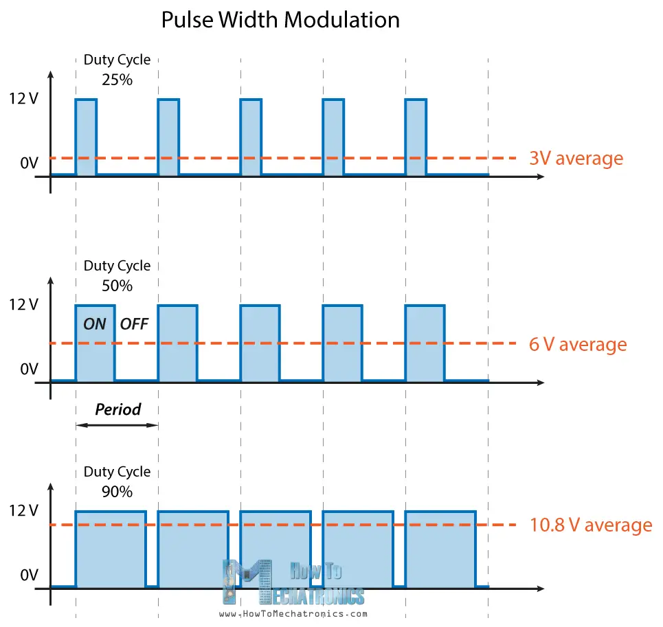
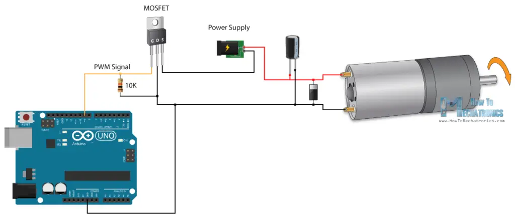
So depending on the size of the motor, we can simply connect an Arduino PWM output to the base of transistor or the gate of a MOSFET and control the speed of the motor by controlling the PWM output. The low power Arduino PWM signal switches on and off the gate at the MOSFET through which the high power motor is driven.
H-Bridge DC Motor Control
On the other hand, for controlling the rotation direction, we just need to inverse the direction of the current flow through the motor, and the most common method of doing that is by using an H-Bridge. An H-Bridge circuit contains four switching elements, transistors or MOSFETs, with the motor at the center forming an H-like configuration. By activating two particular switches at the same time we can change the direction of the current flow, thus change the rotation direction of the motor.
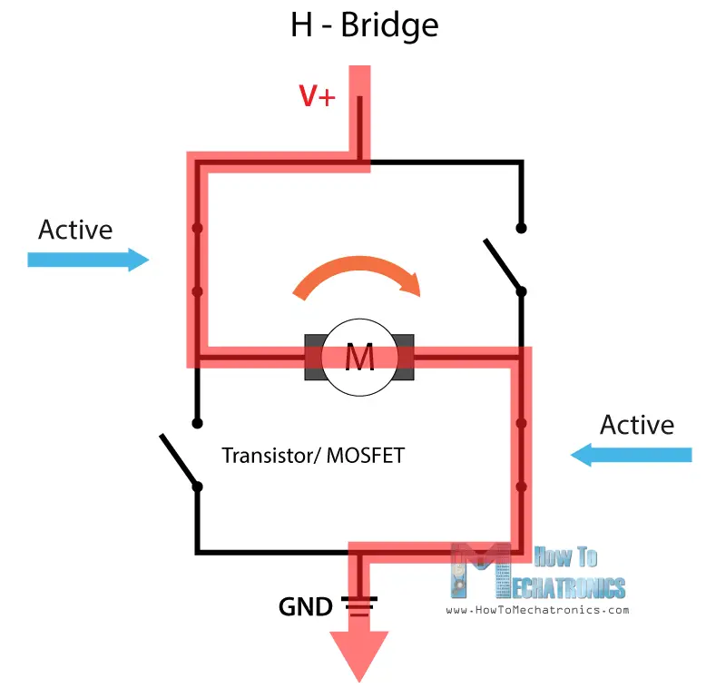
So if we combine these two methods, the PWM and the H-Bridge, we can have a complete control over the DC motor. There are many DC motor drivers that have these features and the L298N is one of them.
L298N Driver
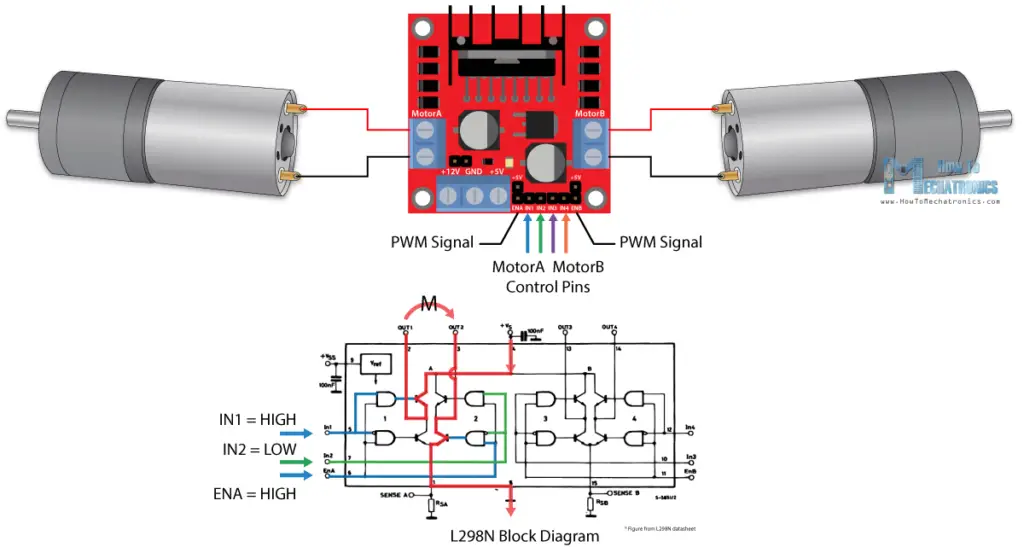
The L298N is a dual H-Bridge motor driver which allows speed and direction control of two DC motors at the same time. The module can drive DC motors that have voltages between 5 and 35V, with a peak current up to 2A.
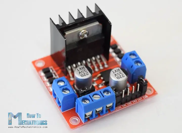
Let’s take a closer look at the pinout of L298N module and explain how it works. The module has two screw terminal blocks for the motor A and B, and another screw terminal block for the Ground pin, the VCC for motor and a 5V pin which can either be an input or output.

This depends on the voltage used at the motors VCC. The module have an onboard 5V regulator which is either enabled or disabled using a jumper. If the motor supply voltage is up to 12V we can enable the 5V regulator and the 5V pin can be used as output, for example for powering our Arduino board. But if the motor voltage is greater than 12V we must disconnect the jumper because those voltages will cause damage to the onboard 5V regulator. In this case the 5V pin will be used as input as we need connect it to a 5V power supply in order the IC to work properly.
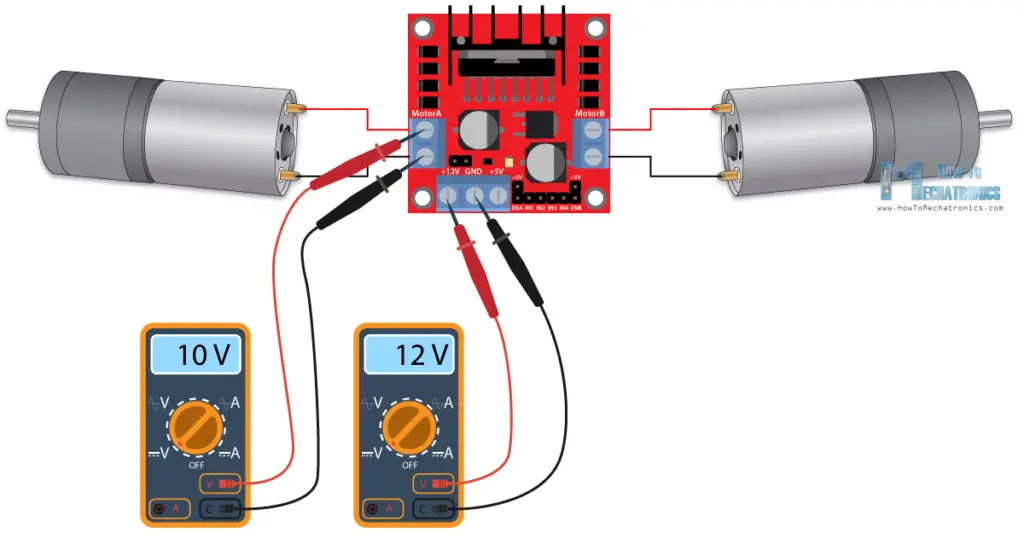
We can note here that this IC makes a voltage drop of about 2V. So for example, if we use a 12V power supply, the voltage at motors terminals will be about 10V, which means that we won’t be able to get the maximum speed out of our 12V DC motor.
Next are the logic control inputs. The Enable A and Enable B pins are used for enabling and controlling the speed of the motor. If a jumper is present on this pin, the motor will be enabled and work at maximum speed, and if we remove the jumper we can connect a PWM input to this pin and in that way control the speed of the motor. If we connect this pin to a Ground the motor will be disabled.
Next, the Input 1 and Input 2 pins are used for controlling the rotation direction of the motor A, and the inputs 3 and 4 for the motor B. Using these pins we actually control the switches of the H-Bridge inside the L298N IC. If input 1 is LOW and input 2 is HIGH the motor will move forward, and vice versa, if input 1 is HIGH and input 2 is LOW the motor will move backward. In case both inputs are same, either LOW or HIGH the motor will stop. The same applies for the inputs 3 and 4 and the motor B.
Arduino and L298N Motor Driver
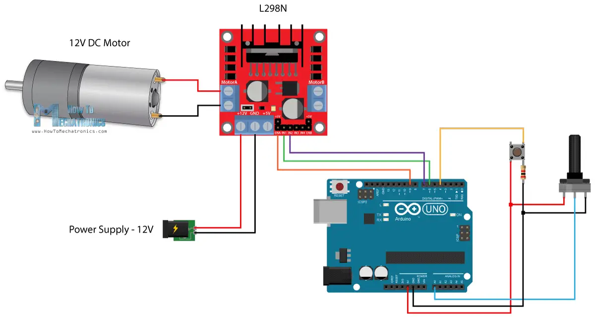
Now let’s make some practical applications. In the first example we will control the speed of the motor using a potentiometer and change the rotation direction using a push button. Here’s the circuit schematics.
So we need an L298N motor driver, a DC motor, a potentiometer, a push button and an Arduino board.
You can get the components needed for this Arduino Tutorial from the links below:
- L298N Driver ……………………………….. Amazon / Banggood / Aliexpress
- 12V High Torque DC Motor ………….. Amazon / Banggood / Aliexpress
- DC Motor w/ Plastic Tire Wheel ……. Amazon / Banggood / Aliexpress
- Arduino Board ……………………………… Amazon / Banggood / Aliexpress
- Breadboard and Jump Wires ………… Amazon / Banggood / Aliexpress
Disclosure: These are affiliate links. As an Amazon Associate I earn from qualifying purchases.
Arduino Code
Here’s the Arduino code:
/*  Arduino DC Motor Control - PWM | H-Bridge | L298N  -  Example 01

    by Dejan Nedelkovski, www.HowToMechatronics.com
*/

#define enA 9
#define in1 6
#define in2 7
#define button 4

int rotDirection = 0;
int pressed = false;

void setup() {
  pinMode(enA, OUTPUT);
  pinMode(in1, OUTPUT);
  pinMode(in2, OUTPUT);
  pinMode(button, INPUT);
  // Set initial rotation direction
  digitalWrite(in1, LOW);
  digitalWrite(in2, HIGH);
}

void loop() {
  int potValue = analogRead(A0); // Read potentiometer value
  int pwmOutput = map(potValue, 0, 1023, 0 , 255); // Map the potentiometer value from 0 to 255
  analogWrite(enA, pwmOutput); // Send PWM signal to L298N Enable pin

  // Read button - Debounce
  if (digitalRead(button) == true) {
    pressed = !pressed;
  }
  while (digitalRead(button) == true);
  delay(20);

  // If button is pressed - change rotation direction
  if (pressed == true  & rotDirection == 0) {
    digitalWrite(in1, HIGH);
    digitalWrite(in2, LOW);
    rotDirection = 1;
    delay(20);
  }
  // If button is pressed - change rotation direction
  if (pressed == false & rotDirection == 1) {
    digitalWrite(in1, LOW);
    digitalWrite(in2, HIGH);
    rotDirection = 0;
    delay(20);
  }
}
Code language: PHP (php)
Description: So first we need to define the pins and some variables needed for the program. In the setup section we need to set the pin modes and the initial rotation direction of the motor. In the loop section we start by reading the potentiometer value and then map the value that we get from it which is from 0 to 1023, to a value from 0 to 255 for the PWM signal, or that’s 0 to 100% duty cycle of the PWM signal. Then using the analogWrite() function we send the PWM signal to the Enable pin of the L298N board, which actually drives the motor.
Next, we check whether we have pressed the button, and if that’s true, we will change the rotation direction of the motor by setting the Input 1 and Input 2 states inversely. The push button will work as toggle button and each time we press it, it will change the rotation direction of the motor.
Arduino Robot Car Control using L298N Motor Driver
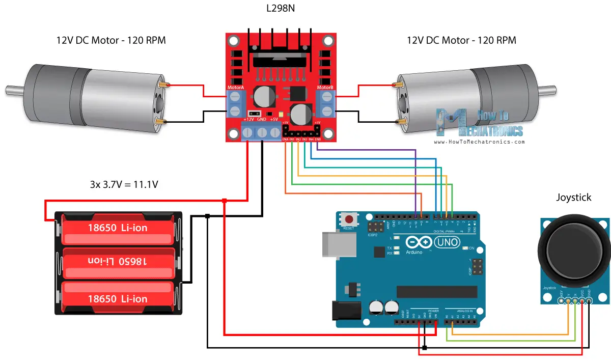
So once we have learned this, now we can build our own Arduino robot car. Here’s the circuit schematic:
All we need is 2 DC Motors, the L298N motor driver, an Arduino board and a joystick for the control. As for the power supply, I chose to use three 3.7V Li-ion batteries, providing total of 11V. I made the chassis out of 3 mm tick plywood, attached the motors to it using metal brackets, attached wheels to the motors and in front attached a swivel wheel.
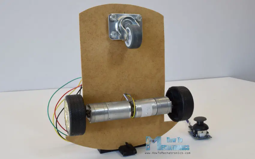
Now let’s take a look at the Arduino code and see how it works. (Down below you can find the complete code)
int xAxis = analogRead(A0); // Read Joysticks X-axis
int yAxis = analogRead(A1); // Read Joysticks Y-axisCode language: JavaScript (javascript)
After defining the pins, in the loop section, we start with reading the joystick X and Y axis values. The joystick is actually made of two potentiometers which are connected to the analog inputs of the Arduino and they have values from 0 to 1023. When the joystick stays in its center position the value of both potentiometers, or axes is around 512.
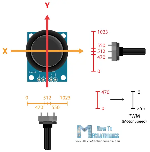
We will add a little tolerance and consider the values from 470 to 550 as center. So if we move the Y axis of joystick backward and the value goes below 470 we will set the two motors rotation direction to backward using the four input pins. Then, we will convert the declining values from 470 to 0 into increasing PWM values from 0 to 255 which is actually the speed of the motor.
// Y-axis used for forward and backward control
  if (yAxis < 470) {
    // Set Motor A backward
    digitalWrite(in1, HIGH);
    digitalWrite(in2, LOW);
    // Set Motor B backward
    digitalWrite(in3, HIGH);
    digitalWrite(in4, LOW);
    // Convert the declining Y-axis readings for going backward from 470 to 0 into 0 to 255 value for the PWM signal for increasing the motor speed
    motorSpeedA = map(yAxis, 470, 0, 0, 255);
    motorSpeedB = map(yAxis, 470, 0, 0, 255);
  }Code language: PHP (php)
Similar, if we move the Y axis of the joystick forward and the value goes above 550 we will set the motors to move forward and convert the readings from 550 to 1023 into PWM values from 0 to 255. If the joystick stays in its center the motors speed will be zero.
Next, let’s see how we use the X axis for the left and right control of the car.
// X-axis used for left and right control
  if (xAxis < 470) {
    // Convert the declining X-axis readings from 470 to 0 into increasing 0 to 255 value
    int xMapped = map(xAxis, 470, 0, 0, 255);
    // Move to left - decrease left motor speed, increase right motor speed
    motorSpeedA = motorSpeedA - xMapped;
    motorSpeedB = motorSpeedB + xMapped;
    // Confine the range from 0 to 255
    if (motorSpeedA < 0) {
      motorSpeedA = 0;
    }
    if (motorSpeedB > 255) {
      motorSpeedB = 255;
    }
  }Code language: JavaScript (javascript)
So again, first we need to convert the X axis readings into speed values from 0 to 255. For moving left, we use this value to decrease the left motor speed and increase the right motor speed. Here, because of the arithmetic functions we use two additional “if” statements to confine the range of the motor speed from 0 to 255.
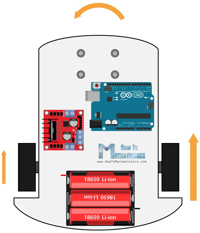
The same method is used for moving the car to the right.
Related: How To Make a PWM DC Motor Speed Controller using the 555 Timer IC
Depending on the applied voltage and the motor itself, at lower speeds the motor is not able to start moving and it produces a buzzing sound. In my case, the motors were not able to move if the value of the PWM signal was below 70. Therefore using this two if statements I actually confined to speed range from 70 to 255. At the end we just send the final motor speeds or PWM signal to the enable pins of the L298N driver.
// Prevent buzzing at low speeds (Adjust according to your motors. My motors couldn't start moving if PWM value was below value of 70)
  if (motorSpeedA < 70) {
    motorSpeedA = 0;
  }
  if (motorSpeedB < 70) {
    motorSpeedB = 0;
  }
  analogWrite(enA, motorSpeedA); // Send PWM signal to motor A
  analogWrite(enB, motorSpeedB); // Send PWM signal to motor BCode language: PHP (php)
Here’s the complete code of the Arduino robot car example:
/*  Arduino DC Motor Control - PWM | H-Bridge | L298N
         Example 02 - Arduino Robot Car Control
    by Dejan Nedelkovski, www.HowToMechatronics.com
*/

#define enA 9
#define in1 4
#define in2 5
#define enB 10
#define in3 6
#define in4 7

int motorSpeedA = 0;
int motorSpeedB = 0;

void setup() {
  pinMode(enA, OUTPUT);
  pinMode(enB, OUTPUT);
  pinMode(in1, OUTPUT);
  pinMode(in2, OUTPUT);
  pinMode(in3, OUTPUT);
  pinMode(in4, OUTPUT);
}

void loop() {
  int xAxis = analogRead(A0); // Read Joysticks X-axis
  int yAxis = analogRead(A1); // Read Joysticks Y-axis

  // Y-axis used for forward and backward control
  if (yAxis < 470) {
    // Set Motor A backward
    digitalWrite(in1, HIGH);
    digitalWrite(in2, LOW);
    // Set Motor B backward
    digitalWrite(in3, HIGH);
    digitalWrite(in4, LOW);
    // Convert the declining Y-axis readings for going backward from 470 to 0 into 0 to 255 value for the PWM signal for increasing the motor speed
    motorSpeedA = map(yAxis, 470, 0, 0, 255);
    motorSpeedB = map(yAxis, 470, 0, 0, 255);
  }
  else if (yAxis > 550) {
    // Set Motor A forward
    digitalWrite(in1, LOW);
    digitalWrite(in2, HIGH);
    // Set Motor B forward
    digitalWrite(in3, LOW);
    digitalWrite(in4, HIGH);
    // Convert the increasing Y-axis readings for going forward from 550 to 1023 into 0 to 255 value for the PWM signal for increasing the motor speed
    motorSpeedA = map(yAxis, 550, 1023, 0, 255);
    motorSpeedB = map(yAxis, 550, 1023, 0, 255);
  }
  // If joystick stays in middle the motors are not moving
  else {
    motorSpeedA = 0;
    motorSpeedB = 0;
  }

  // X-axis used for left and right control
  if (xAxis < 470) {
    // Convert the declining X-axis readings from 470 to 0 into increasing 0 to 255 value
    int xMapped = map(xAxis, 470, 0, 0, 255);
    // Move to left - decrease left motor speed, increase right motor speed
    motorSpeedA = motorSpeedA - xMapped;
    motorSpeedB = motorSpeedB + xMapped;
    // Confine the range from 0 to 255
    if (motorSpeedA < 0) {
      motorSpeedA = 0;
    }
    if (motorSpeedB > 255) {
      motorSpeedB = 255;
    }
  }
  if (xAxis > 550) {
    // Convert the increasing X-axis readings from 550 to 1023 into 0 to 255 value
    int xMapped = map(xAxis, 550, 1023, 0, 255);
    // Move right - decrease right motor speed, increase left motor speed
    motorSpeedA = motorSpeedA + xMapped;
    motorSpeedB = motorSpeedB - xMapped;
    // Confine the range from 0 to 255
    if (motorSpeedA > 255) {
      motorSpeedA = 255;
    }
    if (motorSpeedB < 0) {
      motorSpeedB = 0;
    }
  }
  // Prevent buzzing at low speeds (Adjust according to your motors. My motors couldn't start moving if PWM value was below value of 70)
  if (motorSpeedA < 70) {
    motorSpeedA = 0;
  }
  if (motorSpeedB < 70) {
    motorSpeedB = 0;
  }
  analogWrite(enA, motorSpeedA); // Send PWM signal to motor A
  analogWrite(enB, motorSpeedB); // Send PWM signal to motor B
}Code language: PHP (php)
So that would be all for this tutorial, and in my next video we will upgrade this Arduino robot car, by adding a Bluetooth and Radio devices for enabling smartphone and wireless control.
Feel free to ask any question in the comments section below and don’t forget to check my collection of Arduino Projects.
Hi, I have a question. What is the front wheel control by? I mean what causes the car to go right and left?
The front wheel is not controlled. It just follows the direction that the two wheels on the back side make. It’s a swivel wheel.
I am not sure if this is helpful or just a mistake of mine, but in your diagrams you don’t show a connection between 5v from Arduino board to 5v in the L298N, I mean on top of the 12v from the battery. After trying countless times and isolating the problem when I finally connected those two the circuit worked properly, my theory is that the L298N “logic” device needed the voltage(5v) to work, if that makes sense. I didn’t read all the previous posts to see if this has already been brought up to your attention.
Thank you!
Dear Sergio,
Thank you for the solution.
If it is possible, kindly let me to have further clarification please
1) “I mean on top of the 12v from the battery”, Means supply voltage for the motor is 12 V? This supply voltage is with jumper (voltage jumper) in place or removed?.
Because you have connected Arduino 5 V supply to H-bridge logic 5 V, one can assume that the jumper pin is removed.
I found you tutorial and love how you explain things.
I done your #1 tutorial and the motor runs one speed for a while and than quickly changes direction with out pushing the button, than a second later it switches direction on its own again.
Speed control works fine.
I am using a 7.1 Volt input on the H bridge and the Adruino is plugged into my computer. I grounded the H bridge from the 7.1 volt power supply ( 5 AA batteries) to the ground on Adruino. If I remove this ground cable motor stops running.
Thanks for you advice
Fritz
Good explanation
Thank you for your excellent tutorial. My question relates to Greatisan DC 12v gear motor linked from your website . What does this mean; one way?
“You also can adjust the speed, but the motor speed can only be reduced, can not be raised.”
Well the particular motor has a maximum speed of 100 RPM, so yeah, you can only reduce the speed by applying lower voltage.
Great tutorial! I just have one small problem.
When I hooked up two 12v DC motors to the L298N and an Arduino, the motor on the left spins slightly faster than the one on the right. Is this a connections issue, or is it like this for all cases? By the way, i am not using PWM, so both motors should be running at the same speed. If the power circuit inside the L298N is a series circuit and not a parallel one, then it makes sense for one motor to receive less power than the other, but I don’t think so…
Hey, thanks! Well I haven’t noticed such a behavior. You just have to test it with some other motors and/ or other L298N in order to figure out that’s the problem, it’s either the motors or the driver, but I couldn’t know for sure. Let me know if you find out.
Hi Dejan,
Great tutorial! I have modified the setup to have two joystick controllers. The robot responds for a few seconds and then stops reacting to the joystick controls. What could be the issue? I’ve been thinking it could be a power issue but anything I’ve tried doesn’t seem to work.
Thank you for your help.
Hey, thanks! Yea it might be a power issue. Can you give a bit more info on you project, what motors are you using, what power supple are you using?
Dear Sir
I start learn adruino.
I have project small.
I want to use 1 potentiometer controller DC motor A and B, but motor A turn left and B turn right.
When output sign potentiometer is 2.5 voltage 2 motor stop.
When output sign potentiometer is 2.5- 5voltge motor A turn left and motor B turn right. The speed slow to fast.
When output sign potentiometer is 2.5- 0 voltge motor A turn right and motor B turn left. The speed slow to fast.
Can you help me.
Thanks
Well that’s almost the same as explained in the example with the joystick. The joystick axis is nothing else but a simple potentiometer. When resting in the middle it stays at 2.5V, when it goes forward or backward, the voltage value goes forward to 5V or backward to 0V.
So you just read the analog input, and using the map function you can adjust the receiving values according to your needs.
Hi, I just followed your instructions but to control a kid motor bike, which has two 12v motors, run by 12v battery, unfortunately when I try to run the motor the l293 heate up above 80deg, and motor won’t run , just a jerk only. What can be the reason. Thank you.
Hey, those motors might draw a lot more current than the driver can handle so it heat ups very quickly. Also make sure you double check all the connections.
Awesome, keep it up.
Connected the circuit for variable speed above. motor gets 11.5 volts with no change in speed. The direction can be changed so the push button works. The pot will vary the voltage to A0 from 0 to 5volts. Any advice greatly appreciated
Walter
Well you should send PWM signal to the driver, make sure you have connected those pins to a PWM capable pins on Arduino.
Great explanation!. On the second schematic (where you control the speed of the motor using a potentiometer and rotation using a button) can you tell the resistor ohms rating? Also how is arduino powered on the 5V connector?
What’s the resistor OHMs value that’s connected to the push button on the first diagram?
It can be anything from 1K to 100K ohms.
looking forward to trying this out – this will be my first real arduino project after the “basics” (LED blink etc.). I’m looking to buy all the parts but stumbled when it came to the wheels – can you provide a link or two for where I could get them? I wouldn’t mind spending a little more for something that is good quality.
still very new to all this but, as many others have said, I really appreciate the way you teach these projects!
Well the wheels I used where taken out from a toy car which happened to fit the motors shaft perfectly. You can use DC Motors that come with plastic tire wheel, I’ve just updated the post and included a link to them in the parts list section.
From Colombia, thank you very much for all this time dedicated to explain these issues. The quality of their videos and their explanations are insurmountable, I remain attentive to your channel. Edgardo Hernandez (Google translator)
Dejan, Excellence Job ! Thank you so much . It ‘s very useful for me.
Do you have any Arduino and L298N control code for DC motors by using Remote Control like Flysky ?
Thank so much from Thailand.
Thanks! I’m afraid I don’t have such a example code.
Thank you — very much this was very helpful — you effort is much appreciated — @South Africa 🙂
Dejan,
This is an amazing site and excellent project description. I’m using 2 SYREN controlllers to drive 2-24v motors. SYREN only requires 1 pin to control fwd vs. rev. So I’m only using “in1” and “in3” to control direction. Believe it works as coded however when I move the joystick to the left or the right only one of the motors will rotate. Based on how the code is written I would expect motor A to rotate forward at the same time motor B would rotate backward for a left turn? However only the right motor will move forward when I move the joystick left and then only the left motor will move forward when I move the joystick to the right? Seems like the xmapped code is not working correctly? Any input here would help. thanks..
Hey, thanks Kelly! Well if the joystick is move only right or left, that’s normal, the left or the right motor will move forward and the other motor will not move. I guess your question comes from the two lines where I add and subtract the values from the joystick.In the case of pure left or right movement, one of the PWM values will be negative, but that doesn’t mean the motor will rotate backward, it actually means nothing, no PWM signal. From the above example we can see that for that purpose, for changing the rotation direction we actually use the In1 and In2 control pins of the L298N driver.
I hope that was what you were trying to ask and understand.
Thanks so much for the reply. I’m actually not using the L298N drivers. Using SYREN controllers which only require 1 pin to control fwd and rev.
So yes trying to understand what this code is actually doing;
// Move to left – decrease left motor speed, increase right motor speed
motorSpeedA = motorSpeedA – xMapped;
motorSpeedB = motorSpeedB + xMapped;
when I read this I’m thinking the car has the ability to have a zero turning radius as one motor will accelerate forward while the other accelerates backward when moving the joystick left or right. I actually achieved this by doing the following;
// right turn
if (xAxis 550) {
// Set Motor A backward
digitalWrite(in1, LOW);
// Set Motor B forward
digitalWrite(in3, HIGH);
// Convert the declining x-axis readings for going backward from 470 to 0 into 0 to 255 value for the PWM signal for increasing the motor speed
motorSpeedA = map(xAxis, 550, 1023, 0, 255);
motorSpeedB = map(xAxis, 550, 1023, 0, 255);
}
Great article and well explained project, thank you for the deployed efforts.
well I’ll be using a 24V DC with 4,5 A. as specified, the max current is 2A. therfore, How we can hundle this ? do you know any alternatives ?
To obtain the 24 V we can use 12V adapter plus an LM2596 Buck Converter to convert the 12V to 24V.
but how we can hundle the current ?
thanks in advance.
Houssam
Thanks. The L298N definitely won’t be able to handle that powerful motor. Maybe you should try building your own circuit for driving this motor with higher rated transistors or mosfets which would work in similar way with this driver.
What would recommend if I only need to drive a 1.5v dc motor? A lower voltage driver?
Well it depends what kind of control you want to achieve. You saw here for controlling rotation direction you would need something like H-Bridge, or for controlling the speed you need a PWM signal. As for such a low voltage motor you could use a 1.5V battery for power and simply control a transistor, like shown in the first circuit.
What adjustments should I make if I am using a 24V power supply? Everything else I have is the same as your schematic. Will it damage the boards? Also, thanks for this helpful article.
First you motor must be rated at 24V, then the on-board 5V regulator on your L298N module must be able to handle the 24V, so you can power your Arduino with 5V.
Very good explanation, programs and excellent diagrams.
W. D. Gamini Perera
Galle
Sri Lanka
Thanks!
I like your tutorials very much. You explain things very well and I come away with real understanding. You always give me information that I can really use. Thank you!
Thanks!
Thanks for your work, really helpful.
One question: To which pin do I need to connect the PWM-Signal? I only seem to get an output if I connect both of the pins to the PWM-signal, which doesn’t make sense to me.
Also, now I am in 12V, but I will need to connect a 24V-motor for an other project. Just have to remove that Jumper above the Power input and power the L298 with an external 5V-supply, right? Where would the 5V be connected to GND? Thanks!
Thanks. If using two motors then you need to use the two PWM pins because they are separate channels, A and B. In case you use 24V, then you must remove the Jumper for the 5V regulator, because the 24V are too much for that on-board regulator, but also now you need to connect a separate 5V power supply to the +5V pin on the driver in order the control to work.
On my module there is 78M05 LDO as a 5V regulator. According to the datasheet the input voltage is up to 35V. So the limitation is the power dissipation of the chip only.
So why in voltage above 12V it is necessary to disconnect the regulator?
Did I miss something?
No, you are right. The datasheet states that the 78M05 regulator can handle up to 35V input voltage.
Thanks for the information , i woud like to ask , since the specs say 5v to 35v and max current of 2A, does that mean its possible to drive maybe a linear actuator that is 24 volts with a max current of 0.65A or 1.1A? if i power the H bridge with 24volts?
Well according to the L298 driver datasheet of the total power dissipation is 25W. So yes, at 24 volts you could probably drive a a motor with around 1A.
can i use this IC l298 to drive a 220 V DC motor with PWM , or not ?
thanks for help.
No, you can’t!
This is a very nice project, I love it. But am facing little challenge. The H bridge motor controller am using does nits drive the motor unless I touch the MOSFET’s heat sink. I also try another H bridge still the same thing. Am using 12 volt adapter to power the H bridge.
Try connecting the Arduino GND and the power adapter GND.
I have a few questions regarding this project, Dejan.
You seem to have used Arduino UNO in the pictures, however in the link to Amazon, you have linked Arduino MEGA. Does it make a difference? Could any be used?
And is the joystick also from Arduino? Could we use any joystick?
Also, I would like to get a link of the wires you have used.
I am doing this project and I just do not know how to get the exact components you have used.
P.S, this project is amazing! Thanks a lot!
You can use any Arduino board for this project. A different joystick should work as well. Those wires are so called jumper wires.
This is an amazingly helpful website, thank you!! Really saving my butt on a design project for college.
Thanks!
Hi, Thank you for sharing this very useful tutorial. Can you help me with the code to give half of enA output (0~4.6V). I tried to change the code
“motorSpeedA = map(yAxis, 550, 1023, 0, 255);” to “motorSpeedA = map(yAxis, 550, 1023, 0, 120);”
but, it looks like the range of the joystick a bit, so it hard to increasing the speed smoothly. I need the motor to work at the lowest speed of 1.4V and the maximum speed is 2.1v (about 78~120)
Hey, if you are using a Joystick just like I did, you might have a problem for increasing the speed smoothly, the joysticks aren’t so good. You can try to use potentiometers instead of joystick, for smoother work.
Amigo você estar de parabéns pelo projeto.
Só me confirma umas coisas. posso utilizar o arduino NANO ? Esses último código, é o programa final ? Ou tenho que juntar todos os outros a cima mencionado com esse último ?
Obrigado, e valeu amigo.
Friend you be of congratulations by the project.
Just confirm some things. can I use arduino NANO? Those last code, is the final program? Or do I have to join all the others mentioned above with the latter?
Thanks, and thanks buddy.
Yes, you can use NANO. The last code is the final, the other mentioned are just explanations, all of them are contained in the last final code.
I have to do a similar thing for a school project but i have to amplify arduino’s output voltage to 25V by implementing a external voltage source . Any ideas on how can I do that?
You could use 12V adapter plus an LM2596 Buck Converter to convert the 12V to 24V.
This is a great project. I like it how everything is well explained, not just a plain code and schematics.
Keep up the good work!
Thanks!
really helpful. Thanks for the information.
The first example you gave has some mistakes, and it won’t work if they are not fixed:
1. In the schematics: external power ground must be connected to arduino ground as well, not being isolated as you had indicated there.
2. Variables in1/in2 are OUTPUT not INPUT.
3. (not very important) You never use buttonState variable; it can be removed.
Would you be kind enough to modify that example’s code/schematics?
Thank you.
Thanks for the kind remarks. I’ve updated them.
L298D-Arduino ground shcematic was not shown on the Arduino and L298N in Fritzz scheme.I tried and motor just buzzed until I understood the ground connection is missing.Please modify it.
Thanks for all these tutorials…Take it easyyy.
Very good tutorial sir please show how can we use 4 motors i-e., wheels with it which two motors will be in parallel also show wiring…, Thanks for this!!!
that would be the same just wire multiple motors to the same connector