In this Arduino Tutorial we will learn how to configure and pair two HC-05 Bluetooth Modules as Master and Slave devices.You can watch the following video or read the written tutorial below.
Overview
In my previous two tutorials we already learned how to connect the HC-05 Bluetooth Module to the Arduino and make a communication between an Android smartphone and the Arduino. In those tutorials we used the HC-05 Bluetooth module with its default configuration, as a slave device.
Configuring the HC-05 Bluetooth Module – AT Commands
For this tutorial we need to configure both modules. In order to do that we need to switch to AT Command Mode and here’s how we will do that. First we need connect the Bluetooth module to the Arduino as the circuit schematics explained in the previous tutorials. What we need to do additionally is to connect the “EN” pin of the Bluetooth module to 5 volts and also switch the TX and RX pins at the Arduino Board.
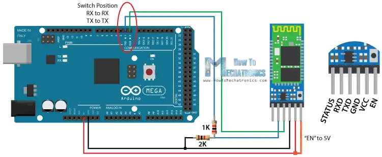
So the RX pin of the Arduino needs to be connected to the RX pin of the Bluetooth module, through the voltage divider, and the TX pin of the Arduino to the TX pin of the Bluetooth module. Now while holding the small button over the “EN” pin we need to power the module and that’s how we will enter the command mode. If the Bluetooth module led is flashing every 2 seconds that means that we have successfully entered in the AT command mode.
After this we need to upload an empty sketch to the Arduino but don’t forget to disconnect the RX and TX lines while uploading. Then we need to run the Serial Monitor and there select “Both NL and CR”, as well as, “38400 baud” rate which is the default baud rate of the Bluetooth module. Now we are ready to send commands and their format is as following.
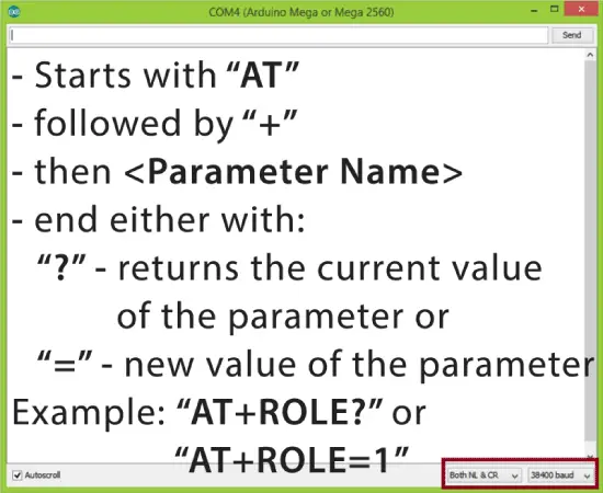
All commands start with “AT”, followed by the “+” sign, then a <Parameter Name> and they end either with the “?” sign which returns the current value of the parameter or the “=” sign when we want to enter a new value for that parameter.
Slave Configuration
So for example, if we type just “AT” which is a test command we should get back the message “OK”. Then if we type “AT+UART?” we should get back the massage that shows the default baud rate which is 38400. Then if we type “AT+ROLE?” we will get back a massage “+ROLE=0” which means that the Bluetooth device is in slave mode. If we type “AT+ADDR?” we will get back the address of the Bluetooth module and it should looks something like this: 98d3:34:905d3f.
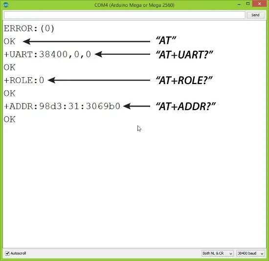
Now we need to write down this address as we will need it when configuring the master device. Actually that’s all we need when configuring the slave device, to get its address, although we can change many different parameters like its name, baud rate, pairing password and so on, but we won’t do that for this example.
Master Configuration
Ok now let’s move on and configure the other Bluetooth module as a master device. First we will check the baud rate to make sure it’s the same 38400 as the slave device. Then by typing “AT+ROLE=1” we will set the Bluetooth module as a master device. After this using the “AT+CMODE=0” we will set the connect mode to “fixed address” and using the “AT+BIND=” command we will set the address of the slave device that we previously wrote down.
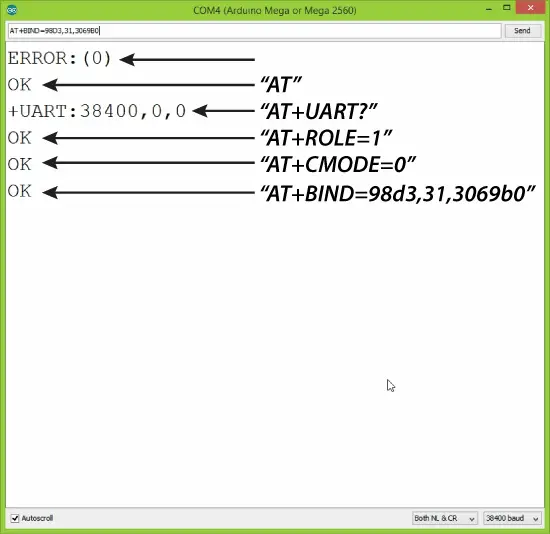
Note here that when writing the address we need to use commas instead of colons. Also note that we could have skipped the previous step if we entered “1” instead of “0” at the “AT+CMODE” command, which makes the master to connect to any device in its transmission range but that’s less secure configuration. Here you can find a complete list of commands and parameters: HC-05 AT Commands List
Nevertheless, that’s all we need for a basic configuration of the Bluetooth modules to work as a master and slave devices and now if we reconnect them in normal, data mode, and re-power the modules, in a matter of seconds the master will connect to the slave. Both modules will start flashing every 2 seconds indicating a successful connection.
Communication Between Two HC-05 Bluetooth Module Example
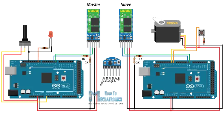
Ok so now we are ready make the practical example for this tutorial. Here’s the circuit schematics. We will use a potentiometer, at the master, to control a servo motor at the slave. And vice versa, we will use a push button, at the slave, to control a LED at the master.
You can get the components needed for this Arduino tutorial from any of the sites below:
- HC-05 Bluetooth Module ……………. Amazon / Banggood / AliExpress
- Arduino Board …………………………… Amazon / Banggood / AliExpress
- Servo Motor…………………………….…. Amazon / Banggood / AliExpress
- Potentiometer……………..………..……. Amazon / Banggood / AliExpress
- 3x 220 Ohms resistors………………… Amazon / Banggood / AliExpress
- Breadboard and Jump Wires ………. Amazon / Banggood / AliExpress
Disclosure: These are affiliate links. As an Amazon Associate I earn from qualifying purchases.
Arduino Source Codes
Description: So first we need to define the pins and some variables needed for the program. In the setup section, at the master, we set the LED pin as output and set it low right away, as well as, start the serial communication at 38400 baud rate. Similar, at the slave, we set the button pin as input, define the servo to which pin is connected and start the serial communication with the same baud rate.
In the loop section, in both code, with the Serial.available() function we will check whether there is available data in the serial port to be read and using the Serial.read() function we will read and store the data into the “state” variable. So if the master receive the character ‘1’ which is sent from the slave when the button state is high, or the button is pressed, the LED will be on. Else if the character is ‘0’ the LED will be off.
As for the servo motor control, first at the master, we read the potentiometer value and map it into a suitable range for the servo from 0 to 255. This value is sent to the slave which use it to rotate the servo motor accordingly. That’s all we need and here’s the demonstration of the example.
Master Code:
/*
 * How to configure and pair two HC-05 Bluetooth Modules
 * by Dejan Nedelkovski, www.HowToMechatronics.com
 *
 *                 == MASTER CODE ==
 */

#define ledPin 9

int state = 0;
int potValue = 0;

void setup() {
  pinMode(ledPin, OUTPUT);
  digitalWrite(ledPin, LOW);
  Serial.begin(38400); // Default communication rate of the Bluetooth module
}

void loop() {
 if(Serial.available() > 0){ // Checks whether data is comming from the serial port
    state = Serial.read(); // Reads the data from the serial port
 }
 // Controlling the LED
 if (state == '1') {
  digitalWrite(ledPin, HIGH); // LED ON
  state = 0;
 }
 else if (state == '0') {
  digitalWrite(ledPin, LOW); // LED ON
  state = 0;
 }
 // Reading the potentiometer
 potValue = analogRead(A0);
 int potValueMapped = map(potValue, 0, 1023, 0, 255);
 Serial.write(potValueMapped); // Sends potValue to servo motor
 delay(10);
}Code language: Arduino (arduino)
Slave Code:
/*
 * How to configure and pair two HC-05 Bluetooth Modules
 * by Dejan Nedelkovski, www.HowToMechatronics.com
 *
 *                 == SLAVE CODE ==
 */

#include <Servo.h>
#define button 8

Servo myServo;
int state = 20;
int buttonState = 0;

void setup() {
  pinMode(button, INPUT);
  myServo.attach(9);
  Serial.begin(38400); // Default communication rate of the Bluetooth module
}

void loop() {
 if(Serial.available() > 0){ // Checks whether data is comming from the serial port
    state = Serial.read(); // Reads the data from the serial port
 }
 // Controlling the servo motor
 myServo.write(state);
 delay(10);

 // Reading the button
 buttonState = digitalRead(button);
 if (buttonState == HIGH) {
   Serial.write('1'); // Sends '1' to the master to turn on LED
 }
 else {
   Serial.write('0');
 }
}Code language: Arduino (arduino)
That’s all and if you have any problems, feel free to ask for help in the comments section below.
HI, I tried the same example, on the receiver end i’m receiving some extra data other than the pot values. what might be the problem? could you please help? Thank you
Hey, the check whether the baud rates of the two modules and the serial monitor are the same, that might be the problem.
yeah I checked many times but still its the same thing. getting some extra bits other than the pot values?
0253
048
050
013
0254
050
057
010
049
057
010
050
013
0254
050
050
i copied this from the serial monitor, the pot was kept at max position do the values of 254 are the pot values but im not understanding what the other values are.
The values other than 254 are ascii characters: digits, plus CR and LF
Please help. I am building a robot, and it does not work. Please tell me how to make it work. Thanks.
Just kidding. Awesome help as always. I’ve learned more from you than I have college textbooks.
Hehe that was a good one. Thanks! 🙂
Hello! I tried this out but it does not work. On the serial monitor for both arduinos only question marks and symbols appear when the button is pressed. How can I fix this? Thank you!
Hey, try to use different baud rates on your serial monitor.
if (state == ‘1’) {
digitalWrite(ledPin, HIGH); // LED ON
state = 0;
}
else if (state == ‘0’) {
digitalWrite(ledPin, LOW); // LED ON
state = 0;
What is the purpose of “state = 0;” ?
thanks
Well it resets the “state” variable to 0 after each iteration. Otherwise if it get the value 1, it will stay in the next iteration as well but we want to be 0.
Hi!! I’m Jan. I am working on an arduino-based bluetooth gamepad for my arduino-based robot. I am planning to connect them so i can control the robot using my gamepad. I have already made the hardware, but having troubles in writing the code. I have a joystick and 4 buttons on my gamepad. All in all i believe there are at least 169 conditions. Will the bluetooth be able to handle those? Or can it just handle 10 conditions from char ‘0’ to ‘9’? For example, will number 12 be sent to the robot as char ‘1’ and char ‘2’? Thank you in advance. I am a big fan of yours. I have been watching your videos for quite a while now. I have started arduino just several months back, i consider myself a newbie. Your videos really help.
Hi there. Well actually you can send even “longer” message, but when receiving you will have to accept it one byte at a time. For example, if you send “Test”, you will receive, ‘T’, ‘e’, ‘s’, ‘t’, so you can add these values into a single String or something, and do what ever you want with them.
You can also check my new tutorial for HC-12 wireless module which works the same way for sending and receiving data, via the serial port. In this tutorial I give explanation for the above example.
Hello, my name is Mike and I’m new to the world of Arduino. Your tutorial is very helpful!, However I can get my HC 05 and HC 05 to pair ( goes from quick flashing to double flash every second or so) but I can see no serial communication between them. I was wondering if it wouldn’t be to much trouble for you to write a tutorial for dummies like me because I can’t fathom what I am doing wrong!, Even something as simple as how to make them say “hi!” To each other. Thank you for helping people like me with your tutorials it is much appreciated!
Hi there and thanks. I do have some other basic tutorials, teaching how to use various pins, serial communication, motors, etc. For start you could go through these other tutorials, and you should be able to learn quite enough.
Thank that helpe me a lot, In the college I have to do a PICONET and this example help me.
Thankyou!
I am having one problem though.
When I pass data from one Arduino to another using two HC05’s, I am getting a two second delay. When I vary the POT, after two seconds(approx), the servo motor rotates.
How should i decrease this delay?
That’s strange. Are you talking about the same example code in this tutorial or another one, as this one should work properly as shown in the video.
Well, I just modified the receiver code a little. I declared ‘state’ as String, since it is taking value from Serial.read(), and hence it will be in String. I then used toInt() function to convert it into an integer value.
very thanks;
how I can connect sim800c to hc-05 module?
Thanks. Sorry but I don’t have any experience with the sim800c.
Hi i keep getting an error 7 when binding to slave to the master and can’t find how to fix it.
can you help me?
Hello Dejan, excellent tutorial, I did it using a hc 05 as master and slave as hc 06, and without the voltage dividers at a baud rate of 9600. Now I want to do this with two servos and two pots. it’s possible?. Could you help me with the code?
Sure it’s possible, you just have to make the code.
Hola podrías ayudar a generar ese código para poder controlar dos o mas servos? muchas gracias excelente tutorial!!!
Thanks for the instructions. Works perfectly thanks
Great, nice to hear this!
How to control two Servo two directions?
With two HC-05 & arduino.
Because this is only one Servo & one directions.
I don’t know how to control two Servo.
It bothers me >_<
hi
I just started searching the way to use the bluetooth module 2 days before. but when i watched your tutorial video, i learnt almost every thing, i wanted to know, just in few minutes.
this is great and very easy to learn tutorial boss.
i have some questions.
if i configure 1 HC-05 as master and other HC-05 as slave on 9600 baud rate, can i use both for simple digital data communication by using both with 2 separate MCUs ?
will these both work full duplex mode ? means if master send any data string to slave so can slave also send any data back to master?
Thanks to help me in advance
Thanks. Yes, I think they can do that job, the slave can send data to the master.
thanks sir
please guide if i configure 1 HC05 as master and other as slave by AT commands and set 9600 buadrate then leave the key sw open circuited. then both connect to normal MCUs like pic or avr or 8951, will these communicate to each other?
Hi, first of all great tutorial :). I have one question. Is it possible to connect for example 1 mster and 5 slaves? If yes how to do that? Should I just write couple of adresses in AT+BIND ?
Hi there and thanks. Well you cannot connect one master to five slaves at the same time.
can you tell me the Bluetooth range of this project? i mean from how far away i will be able to command the servo with the POT?
Approximately 10 meters (30 feet).
How about if I use a HC-05 master and control a HC-6 slave?
It should work the same way.
Hello,
GREAT job on this write up!! Fantastic!
I wanted to know, can a bluetooth phone connect to the master if the master HC-05 is already paired with the other HC-05?
Hi there and thanks!
Well I haven’t tried it but I don’t think it would work as the Master would be already busy.
Tnx Dejan, Great tutorial! For me it worked without the voltage dividers and at a baudrate of 9600.
Thanks, nice to hear that!
Whatever you do, don’t take out the voltage dividers. It smoked when I did that. It may work for a second, but in the end it doesn’t work out.
Yes, that’s correct. The RX pin of the HC-05 module works at 3.3V, there for you need a voltage divider.
Hi I was wondering if you could help me, I am trying to do something really simple with HC-05 but it has become very difficult. I want to send AT commands to the HC-05 from a running Uno sketch. I have HC-05 pins #32 & #34 connected to the Uno so I can control the HC-05 power and AT-state by the Uno. Now I use the Uno to change the state of the HC-05 to AT Command mode, and then send a command by serial.print to the HC-05. But, the HC-05 does not react or respond. I am not sure if not responding, or if I can’t read the response. I am reading the response (debugging) by passing it to the serial monitor. Could you possibly look at my code to help me make this work? Thanks.
Sorry but cannot say anything about this because I have’t tried making such a communication and I don’t have such a code. And sorry but I cannot look or do custom codes when someone ask that from me because it takes quite a time and have a lot other work to do.
Ok, how about any information as how to set up a sleep mode on the hc-05, I think there is the Sniff command but I havent found any documentation for it.
Thanks
Try to find that information from its datasheet.
Hey, I’ve been trying to do the same thing, but I still can not do it. Did you have any success?