In this Arduino Tutorial I will show you how you can make this cool looking radar using the Arduino Board and the Processing Development Environment. You can watch the following video or read the written tutorial below for more details.
Overview
All you need for this Arduino Project is an Ultrasonic Sensor for detecting the objects, a small hobbyist Servo Motor for rotating the sensor and an Arduino Board for controlling them. You can watch the following video or read the written tutorial below.[/column]
Components needed for this Arduino Project
You can get these components from any of the sites below:
- Ultrasonic Sensor HC-SR04 ………… Amazon / Banggood / AliExpress
- Servo Motor……………………………….. Amazon / Banggood / AliExpress
- Arduino Board …………………………… Amazon / Banggood / AliExpress
- Breadboard and Jump Wires ……… Amazon / Banggood / AliExpress
Disclosure: These are affiliate links. As an Amazon Associate I earn from qualifying purchases.
Building the device
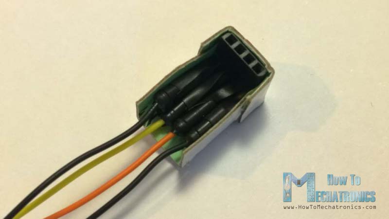
- First I made a cardboard stand for connecting the Ultrasonic sensor to the Servo motor. I folded it like it’s shown on the picture below, glued it and secured to the servo motor using a screw like this.
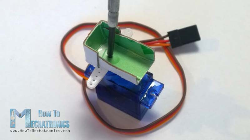
- Also I attached a pin header on which I soldered 4 jumper wires for connecting the sensor.
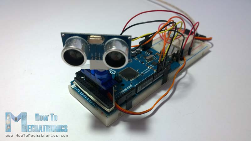
- Finally I secured the servo motor to the Arduino Board using an elastic band.
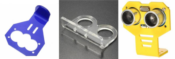
There are also some special mount bracket for the ultrasonic sensor from Banggod. You can get them from the following links:
- Ultrasonic Sensor with Mounting Bracket ……… Amazon / AliExpress
- Mounting Bracket For Ultrasonic Ranging …….. Banggood
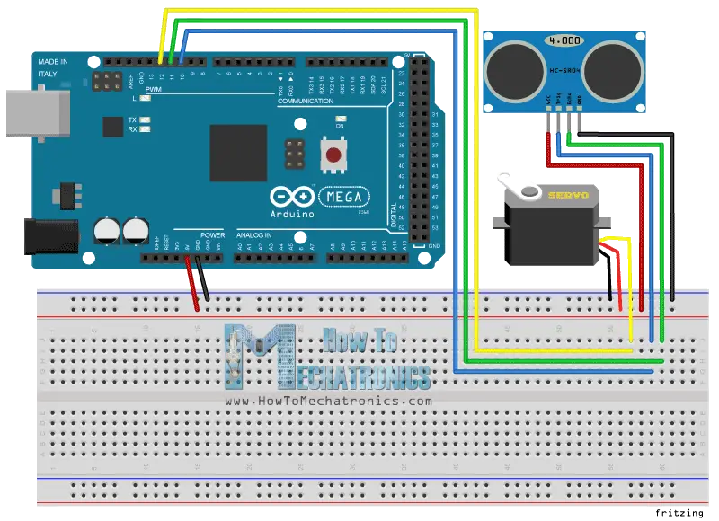
Arduino Radar Circuit Schematics
I connected the Ultrasonic Sensor HC-SR04 to the pins number 10 and 11 and the servo motor to the pin number 12 on the Arduino Board.
Source codes
Now we need to make a code and upload it to the Arduino Board that will enable the interaction between the Arduino and the Processing IDE. For understanding how the connection works click here to visit my Arduino and Processing Tutorial.
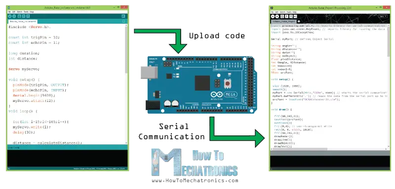
Here’s the Arduino Source Code with description of each line of the code:
// Includes the Servo library
#include <Servo.h>.
// Defines Tirg and Echo pins of the Ultrasonic Sensor
const int trigPin = 10;
const int echoPin = 11;
// Variables for the duration and the distance
long duration;
int distance;
Servo myServo; // Creates a servo object for controlling the servo motor
void setup() {
pinMode(trigPin, OUTPUT); // Sets the trigPin as an Output
pinMode(echoPin, INPUT); // Sets the echoPin as an Input
Serial.begin(9600);
myServo.attach(12); // Defines on which pin is the servo motor attached
}
void loop() {
// rotates the servo motor from 15 to 165 degrees
for(int i=15;i<=165;i++){
myServo.write(i);
delay(30);
distance = calculateDistance();// Calls a function for calculating the distance measured by the Ultrasonic sensor for each degree
Serial.print(i); // Sends the current degree into the Serial Port
Serial.print(","); // Sends addition character right next to the previous value needed later in the Processing IDE for indexing
Serial.print(distance); // Sends the distance value into the Serial Port
Serial.print("."); // Sends addition character right next to the previous value needed later in the Processing IDE for indexing
}
// Repeats the previous lines from 165 to 15 degrees
for(int i=165;i>15;i--){
myServo.write(i);
delay(30);
distance = calculateDistance();
Serial.print(i);
Serial.print(",");
Serial.print(distance);
Serial.print(".");
}
}
// Function for calculating the distance measured by the Ultrasonic sensor
int calculateDistance(){
digitalWrite(trigPin, LOW);
delayMicroseconds(2);
// Sets the trigPin on HIGH state for 10 micro seconds
digitalWrite(trigPin, HIGH);
delayMicroseconds(10);
digitalWrite(trigPin, LOW);
duration = pulseIn(echoPin, HIGH); // Reads the echoPin, returns the sound wave travel time in microseconds
distance= duration*0.034/2;
return distance;
}
Code language: Arduino (arduino)
Now we will receive the values for the angle and the distance measured by the sensor from the Arduino Board into the Processing IDE using the SerialEvent() function which reads the data from the Serial Port and we will put the values of the angle and the distance into the variables iAngle and iDistance. These variable will be used for drawing the radar, the lines, the detected objects and some of the text.
For drawing the radar I made this function drawRadar() which consist of arc() and line() functions.
void drawRadar() {
  pushMatrix();
  translate(960,1000); // moves the starting coordinats to new location
  noFill();
  strokeWeight(2);
  stroke(98,245,31);
  // draws the arc lines
  arc(0,0,1800,1800,PI,TWO_PI);
  arc(0,0,1400,1400,PI,TWO_PI);
  arc(0,0,1000,1000,PI,TWO_PI);
  arc(0,0,600,600,PI,TWO_PI);
  // draws the angle lines
  line(-960,0,960,0);
  line(0,0,-960*cos(radians(30)),-960*sin(radians(30)));
  line(0,0,-960*cos(radians(60)),-960*sin(radians(60)));
  line(0,0,-960*cos(radians(90)),-960*sin(radians(90)));
  line(0,0,-960*cos(radians(120)),-960*sin(radians(120)));
  line(0,0,-960*cos(radians(150)),-960*sin(radians(150)));
  line(-960*cos(radians(30)),0,960,0);
  popMatrix();
}Code language: Arduino (arduino)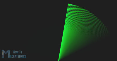
For drawing the line that is moving along the radar I made this function drawLine(). Its center of rotation is set with the translate() function and using the line() function in which the iAngle variable is used the line is redrawn for each degree.
void drawLine() {
  pushMatrix();
  strokeWeight(9);
  stroke(30,250,60);
  translate(960,1000); // moves the starting coordinats to new location
  line(0,0,950*cos(radians(iAngle)),-950*sin(radians(iAngle))); // draws the line according to the angle
  popMatrix();
}Code language: Arduino (arduino)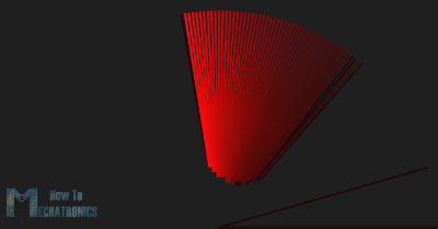
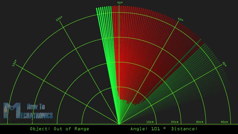
For drawing the detected objects I made this drawObject() function. It gets the distance from ultrasonic sensor, transforms it into pixels and in combination with the angle of the sensor draws the object on the radar.
void drawObject() {
  pushMatrix();
  translate(960,1000); // moves the starting coordinats to new location
  strokeWeight(9);
  stroke(255,10,10); // red color
  pixsDistance = iDistance*22.5; // covers the distance from the sensor from cm to pixels
  // limiting the range to 40 cms
  if(iDistance<40){
    // draws the object according to the angle and the distance
  line(pixsDistance*cos(radians(iAngle)),-pixsDistance*sin(radians(iAngle)),950*cos(radians(iAngle)),-950*sin(radians(iAngle)));
  }
  popMatrix();
}Code language: Arduino (arduino)
For the text on the screen I made the drawText() function which draws texts on particular locations.
All of these functions are called in the main draw() function which repeats all the time and draws the screen. Also here I am using this fill() function with 2 parameters for simulating motion blur and slow fade of the moving line.
void draw() {

  fill(98,245,31);
  textFont(orcFont);
  // simulating motion blur and slow fade of the moving line
  noStroke();
  fill(0,4);
  rect(0, 0, width, 1010);

  fill(98,245,31); // green color
  // calls the functions for drawing the radar
  drawRadar();
  drawLine();
  drawObject();
  drawText();
}Code language: Arduino (arduino)
Here’s the final appearance of the radar:
Here’s the complete Processing Source Code of the Arduino Radar:
import processing.serial.*; // imports library for serial communication
import java.awt.event.KeyEvent; // imports library for reading the data from the serial port
import java.io.IOException;

Serial myPort; // defines Object Serial
// defubes variables
String angle="";
String distance="";
String data="";
String noObject;
float pixsDistance;
int iAngle, iDistance;
int index1=0;
int index2=0;
PFont orcFont;

void setup() {

 size (1920, 1080);
 smooth();
 myPort = new Serial(this,"COM4", 9600); // starts the serial communication
 myPort.bufferUntil('.'); // reads the data from the serial port up to the character '.'. So actually it reads this: angle,distance.
 orcFont = loadFont("OCRAExtended-30.vlw");
}

void draw() {

  fill(98,245,31);
  textFont(orcFont);
  // simulating motion blur and slow fade of the moving line
  noStroke();
  fill(0,4);
  rect(0, 0, width, 1010);

  fill(98,245,31); // green color
  // calls the functions for drawing the radar
  drawRadar();
  drawLine();
  drawObject();
  drawText();
}

void serialEvent (Serial myPort) { // starts reading data from the Serial Port
  // reads the data from the Serial Port up to the character '.' and puts it into the String variable "data".
  data = myPort.readStringUntil('.');
  data = data.substring(0,data.length()-1);

  index1 = data.indexOf(","); // find the character ',' and puts it into the variable "index1"
  angle= data.substring(0, index1); // read the data from position "0" to position of the variable index1 or thats the value of the angle the Arduino Board sent into the Serial Port
  distance= data.substring(index1+1, data.length()); // read the data from position "index1" to the end of the data pr thats the value of the distance

  // converts the String variables into Integer
  iAngle = int(angle);
  iDistance = int(distance);
}

void drawRadar() {
  pushMatrix();
  translate(960,1000); // moves the starting coordinats to new location
  noFill();
  strokeWeight(2);
  stroke(98,245,31);
  // draws the arc lines
  arc(0,0,1800,1800,PI,TWO_PI);
  arc(0,0,1400,1400,PI,TWO_PI);
  arc(0,0,1000,1000,PI,TWO_PI);
  arc(0,0,600,600,PI,TWO_PI);
  // draws the angle lines
  line(-960,0,960,0);
  line(0,0,-960*cos(radians(30)),-960*sin(radians(30)));
  line(0,0,-960*cos(radians(60)),-960*sin(radians(60)));
  line(0,0,-960*cos(radians(90)),-960*sin(radians(90)));
  line(0,0,-960*cos(radians(120)),-960*sin(radians(120)));
  line(0,0,-960*cos(radians(150)),-960*sin(radians(150)));
  line(-960*cos(radians(30)),0,960,0);
  popMatrix();
}

void drawObject() {
  pushMatrix();
  translate(960,1000); // moves the starting coordinats to new location
  strokeWeight(9);
  stroke(255,10,10); // red color
  pixsDistance = iDistance*22.5; // covers the distance from the sensor from cm to pixels
  // limiting the range to 40 cms
  if(iDistance<40){
    // draws the object according to the angle and the distance
  line(pixsDistance*cos(radians(iAngle)),-pixsDistance*sin(radians(iAngle)),950*cos(radians(iAngle)),-950*sin(radians(iAngle)));
  }
  popMatrix();
}

void drawLine() {
  pushMatrix();
  strokeWeight(9);
  stroke(30,250,60);
  translate(960,1000); // moves the starting coordinats to new location
  line(0,0,950*cos(radians(iAngle)),-950*sin(radians(iAngle))); // draws the line according to the angle
  popMatrix();
}

void drawText() { // draws the texts on the screen

  pushMatrix();
  if(iDistance>40) {
  noObject = "Out of Range";
  }
  else {
  noObject = "In Range";
  }
  fill(0,0,0);
  noStroke();
  rect(0, 1010, width, 1080);
  fill(98,245,31);
  textSize(25);
  text("10cm",1180,990);
  text("20cm",1380,990);
  text("30cm",1580,990);
  text("40cm",1780,990);
  textSize(40);
  text("Object: " + noObject, 240, 1050);
  text("Angle: " + iAngle +" °", 1050, 1050);
  text("Distance: ", 1380, 1050);
  if(iDistance<40) {
  text("        " + iDistance +" cm", 1400, 1050);
  }
  textSize(25);
  fill(98,245,60);
  translate(961+960*cos(radians(30)),982-960*sin(radians(30)));
  rotate(-radians(-60));
  text("30°",0,0);
  resetMatrix();
  translate(954+960*cos(radians(60)),984-960*sin(radians(60)));
  rotate(-radians(-30));
  text("60°",0,0);
  resetMatrix();
  translate(945+960*cos(radians(90)),990-960*sin(radians(90)));
  rotate(radians(0));
  text("90°",0,0);
  resetMatrix();
  translate(935+960*cos(radians(120)),1003-960*sin(radians(120)));
  rotate(radians(-30));
  text("120°",0,0);
  resetMatrix();
  translate(940+960*cos(radians(150)),1018-960*sin(radians(150)));
  rotate(radians(-60));
  text("150°",0,0);
  popMatrix();
}
Code language: Arduino (arduino)
New Updated version of the Arduino Radar code to fit any screen resolution:
Just change the values in size() function, with your screen resolution.
/*   Arduino Radar Project
 *
 *   Updated version. Fits any screen resolution!
 *   Just change the values in the size() function,
 *   with your screen resolution.
 *
 *  by Dejan Nedelkovski,
 *  www.HowToMechatronics.com
 *
 */

import processing.serial.*; // imports library for serial communication
import java.awt.event.KeyEvent; // imports library for reading the data from the serial port
import java.io.IOException;

Serial myPort; // defines Object Serial
// defubes variables
String angle="";
String distance="";
String data="";
String noObject;
float pixsDistance;
int iAngle, iDistance;
int index1=0;
int index2=0;
PFont orcFont;

void setup() {

 size (1920, 1080); // ***CHANGE THIS TO YOUR SCREEN RESOLUTION***
 smooth();
 myPort = new Serial(this,"COM4", 9600); // starts the serial communication
 myPort.bufferUntil('.'); // reads the data from the serial port up to the character '.'. So actually it reads this: angle,distance.
 orcFont = loadFont("OCRAExtended-30.vlw");
}

void draw() {

  fill(98,245,31);
  textFont(orcFont);
  // simulating motion blur and slow fade of the moving line
  noStroke();
  fill(0,4);
  rect(0, 0, width, height-height*0.065);

  fill(98,245,31); // green color
  // calls the functions for drawing the radar
  drawRadar();
  drawLine();
  drawObject();
  drawText();
}

void serialEvent (Serial myPort) { // starts reading data from the Serial Port
  // reads the data from the Serial Port up to the character '.' and puts it into the String variable "data".
  data = myPort.readStringUntil('.');
  data = data.substring(0,data.length()-1);

  index1 = data.indexOf(","); // find the character ',' and puts it into the variable "index1"
  angle= data.substring(0, index1); // read the data from position "0" to position of the variable index1 or thats the value of the angle the Arduino Board sent into the Serial Port
  distance= data.substring(index1+1, data.length()); // read the data from position "index1" to the end of the data pr thats the value of the distance

  // converts the String variables into Integer
  iAngle = int(angle);
  iDistance = int(distance);
}

void drawRadar() {
  pushMatrix();
  translate(width/2,height-height*0.074); // moves the starting coordinats to new location
  noFill();
  strokeWeight(2);
  stroke(98,245,31);
  // draws the arc lines
  arc(0,0,(width-width*0.0625),(width-width*0.0625),PI,TWO_PI);
  arc(0,0,(width-width*0.27),(width-width*0.27),PI,TWO_PI);
  arc(0,0,(width-width*0.479),(width-width*0.479),PI,TWO_PI);
  arc(0,0,(width-width*0.687),(width-width*0.687),PI,TWO_PI);
  // draws the angle lines
  line(-width/2,0,width/2,0);
  line(0,0,(-width/2)*cos(radians(30)),(-width/2)*sin(radians(30)));
  line(0,0,(-width/2)*cos(radians(60)),(-width/2)*sin(radians(60)));
  line(0,0,(-width/2)*cos(radians(90)),(-width/2)*sin(radians(90)));
  line(0,0,(-width/2)*cos(radians(120)),(-width/2)*sin(radians(120)));
  line(0,0,(-width/2)*cos(radians(150)),(-width/2)*sin(radians(150)));
  line((-width/2)*cos(radians(30)),0,width/2,0);
  popMatrix();
}

void drawObject() {
  pushMatrix();
  translate(width/2,height-height*0.074); // moves the starting coordinats to new location
  strokeWeight(9);
  stroke(255,10,10); // red color
  pixsDistance = iDistance*((height-height*0.1666)*0.025); // covers the distance from the sensor from cm to pixels
  // limiting the range to 40 cms
  if(iDistance<40){
    // draws the object according to the angle and the distance
  line(pixsDistance*cos(radians(iAngle)),-pixsDistance*sin(radians(iAngle)),(width-width*0.505)*cos(radians(iAngle)),-(width-width*0.505)*sin(radians(iAngle)));
  }
  popMatrix();
}

void drawLine() {
  pushMatrix();
  strokeWeight(9);
  stroke(30,250,60);
  translate(width/2,height-height*0.074); // moves the starting coordinats to new location
  line(0,0,(height-height*0.12)*cos(radians(iAngle)),-(height-height*0.12)*sin(radians(iAngle))); // draws the line according to the angle
  popMatrix();
}

void drawText() { // draws the texts on the screen

  pushMatrix();
  if(iDistance>40) {
  noObject = "Out of Range";
  }
  else {
  noObject = "In Range";
  }
  fill(0,0,0);
  noStroke();
  rect(0, height-height*0.0648, width, height);
  fill(98,245,31);
  textSize(25);

  text("10cm",width-width*0.3854,height-height*0.0833);
  text("20cm",width-width*0.281,height-height*0.0833);
  text("30cm",width-width*0.177,height-height*0.0833);
  text("40cm",width-width*0.0729,height-height*0.0833);
  textSize(40);
  text("Object: " + noObject, width-width*0.875, height-height*0.0277);
  text("Angle: " + iAngle +" °", width-width*0.48, height-height*0.0277);
  text("Distance: ", width-width*0.26, height-height*0.0277);
  if(iDistance<40) {
  text("        " + iDistance +" cm", width-width*0.225, height-height*0.0277);
  }
  textSize(25);
  fill(98,245,60);
  translate((width-width*0.4994)+width/2*cos(radians(30)),(height-height*0.0907)-width/2*sin(radians(30)));
  rotate(-radians(-60));
  text("30°",0,0);
  resetMatrix();
  translate((width-width*0.503)+width/2*cos(radians(60)),(height-height*0.0888)-width/2*sin(radians(60)));
  rotate(-radians(-30));
  text("60°",0,0);
  resetMatrix();
  translate((width-width*0.507)+width/2*cos(radians(90)),(height-height*0.0833)-width/2*sin(radians(90)));
  rotate(radians(0));
  text("90°",0,0);
  resetMatrix();
  translate(width-width*0.513+width/2*cos(radians(120)),(height-height*0.07129)-width/2*sin(radians(120)));
  rotate(radians(-30));
  text("120°",0,0);
  resetMatrix();
  translate((width-width*0.5104)+width/2*cos(radians(150)),(height-height*0.0574)-width/2*sin(radians(150)));
  rotate(radians(-60));
  text("150°",0,0);
  popMatrix();
}Code language: Arduino (arduino)
Hey can you give a rough estimate on the forward range of the radar?
The max range of the ultrasonic sensor is 4 meters.
Thanks for setting up a nice project. I was able to follow and my project works. The only issues i found that the scanning is not very fast. I tired to reduce the angle and at the end looked into increasing the serial baud rate which didn’t resulted in fast scanning. Serial monitor always showed very same reading speed. So, the radar lines on frame move very slowly and distance get updated slow when compared to you video.
Thanks! Well try to increase the servo speed by adjusting the delay time in the “for” loop for driving the servo.
Good job, this is a good idea to learn how radar work.
hi, i want to construct it for my school project. but i just have a week for that. can it be made that easily? in addition to that i have zero knowledge of arduino devices. should i just follow the steps? or is there any more explanation on your site? being honest i m really confused
Hi there, well if you follow all the steps from the video and the article the project should work. There isn’t anything hidden, though you would need a bit of knowledge in case you connect something wrong, because you will wonder that is going on. Check my other beginner tutorials if you are complete beginner.
I realize I’m just another voice in the choir, here, but I feel I have to say it anyway: This was a delightfully whimsical project. I did “just because”, and it was very fun. Thanks! I learned a handful of things that may turn out ot be useful, later on.
I’m so glad to hear this, thank you!
Really cool tutorial!
I was just wondering if there was a way to use that GUI on the 3.1″ TFT Screen you also made a tutorial of?
Thanks! Of course, everything is possible with Arduino, but that would requite appropriate code changes. You would have to code the GUI to suit the TFT screen.
Work great. Very nice project. Thank you.
god bless you sir . You have a good kind heart. Thankyou soo much
How can I change the colors of the radar lines, arcs and the object detection lines(red)?
Sure, you can change that in the Processing code.
Really cool project! And, it was easy enough for me to pull off with only minimal mess ups. I only first bought an Arduino (Uno R3+) 3 days ago. I went through all of the tutorials in the starter kit I bought, and then purchased some other stuff to add on to it (shields, sensors, etc.).
I really appreciate the tutorial on setting up and working with Processing, as well. I didn’t know about that before, but now can add that into my learning. Thanks!
I’m glad to hear this. Thanks!
can you publish the libraries needed for the code please
You don’t need any external library for this project. The servo library is included with the installation of the Arduino IDE.
Yes sorry I found that. But also in the latest ‘complete source code’ bit, there is no #include and I am getting confused and I have already written half of the the code titled in red letters. Help!
Great site, great project and thanks for making everyting fun and easy.
I just wanted to ask that, is it possible to adapt the code for measuring the speed of an approaching object. I reduced the angle of scanning to 60 degrees and I want to see the speed on the screen if an object is getting closer to the sensor. Any tips to get me started?
Thanks in advance.
Thanks. That sounds like a good project idea and you might be able to make it with this or similar sensor and setup. You comparing the distanced the object has approached in a particular period of time.
Dejan, The project is excellent. The code all works and the instructions and tutorials are excellent. My only trouble was finding out how to clear the font error in Processing but a quick google search taught me how to create the font. It’s a great project!
is it possible to use the processing code to make it 360 and will it work with the existing arduino code?
Well the servo motor can only rotate 180 degrees. You would need different motor, so different code for both Arduino and processing. But sure, it’s possible to make it.
hi i just want to ask how can i match the distance of the detected object in the sonar since i already change the distance that the sensor to 1m, the distance that the sonar give doesnt match with the distance that the sensor detect
hi i just want to ask if i can display the sonar in something like mobile phone, is it possible to do that?
It’s possible but you would have to make a suitable application for your mobile. I already have a tutorial on how to make your own custom Android application using the MIT App Inventor, so you can check it out and find some more details there.
can you give me the link? i cant find it sorry
Can I work with the arduino one?
Yes sure, you can use any Arduino board for the project.
Sir,
Is there any different code for different aurdino
It’s the same code.
Hi Dejan,
I get the program to work some of the time, but not every time. The sensor will often hesitate on the swing back (165 to 15 degrees) at about 80 to 90 degrees and then will often hesitate on the swing forward (15 to 165 degrees) at about 70-80 degrees. Any idea why it hesitates on the swing back and forward? What is weird, is that sometimes it doesn’t hesitate at all, but most of the time it does. Any help would be appreciated.
arduino uno r3 is working ?
Yes, sure.
Thanks a ton man!. The project definitely works. The coding is free of error. There is just one slight modification though. The font which you use in the processing IDE needs to be moved into the sketch folder first and you seem to have skipped mentioning that part.
Other than that, this one is an awesome project indeed.
Cheers
I’m glad you find it interesting. Thanks!
I Dejan,
Just finished building your Radar Program. Works Great! Loved making it. Only problems with font and ports. Thanks for sharing it with us.
Great, nice to hear that!
How did you solve the fonts and ports problem?
Check some of the other comments.
Hello there!
can you explain the formula used for the distance
distance= duration*0.034/2;
how you got to it, if you may please?
Hello and thank you for this project, its really nice
I have a problem but beside this all is good
The problem is the servo motor is not rotating smoothly I always have to push it and force it to rotate it does not rotate on itself
Can you help me?
It seems like your Arduino doesn’t have enough power to run the servo motor smooth (although this shouldn’t happen) or your servo motor might be faulty.
Thank-you
the motor was the problem I think
What is the sensor detecting? metal, object, plastic?
Anything that reflects sound.
The ultrasonic sensor u used for this project is HC- SR04. I read data sheet of it. range of sensor is upto 400 cm. then why only upto 40 cm can be got by this code. if we consider its measuring efficiency is lesser than ideal one then also it could measure atleast upto 100cm. What changes in code required if i want output of 400cm or 100cm.
Yes, you can change the range, I have already give suggestion how to do this in a previous comment. Try my comment from February 19, 2016.
Sir, how can I run that graphics code? which software used for radar graphical display?
The graphics is made using Processing IDE.
I need the most high possible precision for my project but this code (processing code) is not very precise. Arduino and the sonar are working good, sending the right distance to the serial port. Processing IDE is recieving the right distance but the results showed by the radar are not! The value showed near “Distance” is correct but the red line is wrong by 3, sometimes 4 cm. Also, the segment from point 0 and 10 cm is much bigger then segments between 10-20, 20-30 and 30-40. I also modified the processing code to show red lines only at a certain distance (eg. 10cm) to see exactly how much is the red line long when processing read 10cm from the serial port and the red line is at about 7/8cm (so it starts before the 10cm segment). Same as for 20cm or any other distance.
That’s true, this project is not that accurate, considering both the cheap electronics components used in this project, as well as the coding in the Processing IDE. The point was to make it as simple as possible so that everyone can easily understand it and make it on their own, and sure there is always room for any project to be improved.
Thanks Brother Everything went smoothly. I appreciate you for sharing this project with us.
Can you do the same project with Raspberry Pi please?
Hi there I’m sorry to bother you. Can I able to use arduino uno r3 instead of arduino mega 2560?
Yes, sure you can.
Thanks you for sharing sir. I tried it and it was very useful for me. very happy with that. 🙂 Thanks a lot.
Great, have fun!
Can i make the radar screen with LCD touch screen 2.8 or 3.2 inch? And if the answer is yes, can you give the code with LCD screen (processing code). thanks very much bro!
That’s a different approach to this project. You would need to program the Arduino to display the radar on the LCD, you won’t need Processing code. I don’t have such a code though.
It Works!! Just replaced “30” to “48” (in orcfont line) in latest processing IDE(3.2.3) and adjusted the screen size.
That’s great, have fun!
You are awesome bro! I’m looking for this project a month now. I will try to test this one later, thanks a lot!
Thank you! Have fun making it!
I am using Arduino nano but the speed of server motor is very slow. pliz suggest me.
Try reducing the delay time.
sir
how you connect this project to samsung screen ???
It’s a Desktop PC monitor.
hey, i really like this project you have, but I am having, is that for starters the screen for some reason does not fit, but my main problem is that the red lines are not showing up for me when i run the program. everything else is working fine, the green lines are moving and all, but when i place somthing in front of the sensor, no red lines appear. do you know how to fix this? thanks for the help
Make sure you are using the correct, updated, Processing IDE code which can fit any screen resolution.
i have made it….. thanks for sharing bro!!!
Great, I’m happy to hear that! 🙂
Nice tutorial! I was wondering if it would be possible to operate the device without having the board connected to the computer?
Thanks. Well not really, you need to have the Processing IDE running and you need a monitor to display it.
Hi. I made this project. It was a success. But, I have a question. I need do it with bluetooth. could you help me?
That’s great. Well check my Arduino Bluetooth tutorial, learn how the Bluetooth communication work and make the project. 🙂
Hi Dejan!! Can You Tell Me How Can I Make A Similar Radar Like You Using A Stepper Motor Instead Of Using Servo Motor???
Hi there. Well you will have to replace the servo motor with a stepper motor and modify code according your motor and driver.
Is This Arduino Code Is Correct Or Not For THis Radar By Using Stepper Motor:-
// Including Required Libraries
#include // Library For Stepper
#include // Library For SONAR
AF_Stepper Radar(200, 2); // Stepper Configuration For Port Number And Steps/Revolution
#define PING_PIN 12 // Arduino Pin 12 Connected To Ping pin Of HC-SR04
NewPing sonar(PING_PIN, PING_PIN); //Sensor Configuration
unsigned int distance1; // Variable For Storing Sensed Distance
unsigned int distance2;
void setup()
{
Serial.begin(9600); // Initializing Seial COmmunication At 9600bps
Radar.setSpeed(20); // Configuring Stepper RPM
}
void loop()
{
for(int i = 0; i = 0; i–)
{
Radar.step(1, BACKWARD, SINGLE);
delay(5);
distance2 = sonar.ping() / US_ROUNDTRIP_CM;
delay(5);
Serial.print(i*1.8);
Serial.print(“,”);
Serial.print(distance2);
Serial.print(“.”);
}
Thank you man this is a great job!!
It works perfect I only have to change 2 things to make it work on ubuntu, this is one of them:
I change this:
myPort = new Serial(this,”COM4″, 9600);
to my ubuntu serial:
myPort = new Serial(this,”/dev/ttyUSB0″, 9600);
And the font too:
myFont = createFont(“Georgia”, 32);
But wen I change the SCREEN RESOLUTION the draw of the void drawRadar is more small than the lines.
how can I fix the screen resolution to match with? size (1100, 880);
thank you for this great tutorial I really appreciate it!
Are you using the right Processing IDE code, the updated to work on each screen resolution, the one on the bottom of the post. If you are using that one you just have to set your screen resolution and all other drawings will be adjusted according to the set resolution.
Hello sir!
I’m having a small problem. The green and red lines are not moving at all and the angle is only showing 0° all the time. Please give me some instructions of solving this problem!
Thank’s for a cool Project!
Check your connections twice, you probably have connected something wrong. Test the sensor whether is working with the simple tutorial code for the ultrasonic sensor.
The lines plotted are only red, its always In Range, and the distance is not calculating on the plot, it’s at zero. I made another project to test the pinger, and it works. What should i try next?
It must be something with the ultrasonic sensor as it gives zero. Double check your connection and pin numbers defined in the Arduino code.
Hi sir, thank you for your great tutorial ! but I have a problem. It says in the Processing IDE that “Could not load font OCRAExtended-30.vlw. Make sure that the font has been copied to the data folder of your sketch.”. Can you help me out sir , please ?
Thanks. Please check the other comments, this question has already been answered.
Hi Dejan,
Great project. Even I have followed and done it. Everything is working fine but the problem I am facing is that my servo motor is getting hot and after 1 or 2 rotation it stops rotating and then it doesn’t rotate till it doesn’t cool down. May be next day it start to work and again after 2 roation it heats up and stops.
I want to just ask you that whatever distance which is measured, I want it to be uploaded to my Cloud, So can I do that? Can you help me out? Please.!
Hi,
Well you might have a faulty servo motor.
Sure you could store your measurements, but I don’t have any tutorial about storing them on Cloud. If storing them to a MicroSD card could do the job for you, you can check my particular tutorial for that.
sir, how can we send data using arduino+ bluetooth module to prossesing , thank you
Take a look at my Arduino Bluetooth Tutorial, it might be helpful.
Hi,
Really helpful tutorial.
I am experiencing really noisy HC-SR04 data. I was wondering if you have experienced that and if so how did you solve it. Or do you have any advice on what might be the problem.
Thanks! I haven’t got any problem with the HC-SR04 sensor date, it worked nice and stable. I couldn’t say anything, it might be a faulty sensor.
Hello Dejan
Where i can download the library for the radar monitor ?
IOEXEPITION library
KeyEvent library
Thank you for your help
You don’t need any external library for this project. It uses the Arduino and Processing IDE default libraries.
Hi, one basic doubt I’m facing, pardon me if i’m being a stupid here.
How’s the angle measured from the data ? Considering ultrasonic sensor returns only the distance to an object.
The angle depends from the angle of the servo motor.
Hey, great project!!! 🙂
But I wanted to know how can we make it rotate 360 degrees because the servo can rotate up to 190 degrees. Can we have a wireless radar configuration for making it rotate 360 degrees or a sensor equivalent to 360 radiation pattern?
pls help me out!!!
Thank u
Thanks!
Sure, everything is possible but I don’t see how I can help you.
Hi Dejan the error message that i am getting is ‘import’ does not name a type what should i do with it? thank you!
Hi Dejan I would like to know how did you set up the screen and how to connect it in order to have the green radar lines going on if you could explain me this thank you I already scrolled the other comments…
Jonny
Hi there. Everything is already explained in the article, I don’t see what else can I say…
Hi Dejan thanks for the prompt reply, I am trying to compile the code but i get errors could you send me a link of the latest code bro thank you!
Jonny
Is there a way to do this with a three-pin ultrasonic sensor? Or, if there isn’t, what is the fourth pin for?
Well the one with 3 pins is a bit different module but it can be used for the same project. You just need to modify the code appropriately.
Hello
I am really new using arduino. I see that the code that you gave us is in 6 parts. How i mixed up?
thank you
There is one Arduino code and one Processing IDE code. Everything is stated well in the post, which of them where it needs to be used.
Great project! However I did have a problem downloading the processing sketch for the screen. Do you know why? Thanks.
Thanks!There shouldn’t be any problem. What kind of problem do you have?
Hey Dejan. Great instruction. Heres a demo of a makealike with the help of one of my kids..
https://youtu.be/ny7O03J-pRE
Thanks! That’s really great. 🙂
Hi friend! Great design!
How would the code to display this on a TFT LCD screen 3.2″ ?
Thank you
Thanks. Well I don’t have such an code, but it’s probably possible to be done.
Hi again,
The resolution issue is solved. I think I had used a previous version of your code, I see that all graphics are sized for width and height of the size() function.
Thanks!
Great, I’m so glad to hear that it worked for you and that the students had fun making it. 🙂
Hi Dejan,
Thanks for making this project available, it’s very impressive. We brought it to a group of about 60 students and they made it. All were very impressed with the results.
I’ve done it on my computer and it works very well. On the student laptops, coming with many different setups, screen resolutions and operating systems, we had issues on some. The main one was with resolution. Even using your last code for all screen resolution, and changing the “size (1920, 1080); ” line with their respective screen resolution did not change the size of the radar graph. We can only see the top left corner of the radar, with the base and angles-distances out of the screen. This mainly happened with the lower screen resolutions, around 1360, 768. I think other feedbacks mentioned this as well, I’m trying to troubleshoot on my computer but if you can help it would be great.
Others were getting error messages when compiling the Arduino code, I’m thinking it could be linked to their antivirus softwares as they were getting prompts from it. Anyway we’ll work through this one.
Thanks again for sharing this code, it made the kids very happy!
Very cool project! Thanks for sharing! Worked great after I fixed the problem with the font.
Thanks, nice to hear that it worked for you!
I made it…….thanks for the guidance
Great, have fun! 🙂
Hello Sir,
I have a problem with Processing. Last time I used this app everything functioned. Now the radar’s drawing is broke. I can’t attach a picture to show you what is happening. Radar appear regular when I open Processing but it doesn’t scan the near environment. It just draw a bold red line from the center to the begining degree of scanning.
You might be having a problem with the ultrasonic sensor not giving the correct values. Check them via the Arduino Serial Monitor first.
The sensor is working 🙁 , the servo-motor is working
I tried to change pins in the testing program for the sensor with the pins 10 and 11 and the sensor is working. do you know another software like processing?
Hi, My daughter is about to do this project with her weekend Science group (all 12 years old).
I just wanted to say that the code and the video and the explanations are excellent, and I think this will be an excellent project for them.
I am also going to use it to introduce the concept of Radians to them, as a side note.
Many thanks for your all your efforts and explanations and tutorials. A truly inspirational site.
I’m so glad to hear this, thank you!
My daughter has done the project, and it worked perfectly first go!
Excellent.
(Did not use the updated code version, just the original).
Many thanks again.
Great, I’m so glad to hear this!
Sir im using ubuntu and i have problem with that processing code. Its says port error!!
Help!!
Well yes, the line for defining the port should should be modified. Each OS needs different definition.
Hello dejan,
Thank you for the great project!!!
I have a question regarding the display. after clicking the run button in processing, my display only shows partial screen of the scanning radar. Changing the display resolution does not fix the problem. I also change to different font. Please help.
Thanks in advance.
Did you use the updated code at the bottom of the article?
Thanks for the reply,
Yes, I used the updated code at the bottom of the article. As instructed I change the size() to 1600 x 900 as recommended by my display setting.
hello sir dejan, how do we connect the ultrasonic sensor with the laptop screen? which code should i modify?
Through the Arduino, the Serial Communication and Processing IDE.
sir dejan, i still blurred on the step.. can you please show me in detail? i am still new with arduino ..
sir dejan, or maybe you just give me the lines for arduino code to connect the ultrasonic sensor with laptop screen.. thankyou
Hello
Should I use mini servo for this procect? If I use a bigger servo,do I need to modify anything in the code?
Well it depends whether the servo is driven in the same way as the mine.
Hello Sir, for the updated display code I am getting an error which reads:
exit status 1
‘import’ does not name a type
This error is for this code “import java.io.IOException;”
You are messing things up. You are using an Arduino code in Processing IDE.
I figured out what I was doing wrong and the project is working well.
Can I integrate the display on an LCD?
I have a 3.2′ TFTLCD Shield for Arduino Mega2560.
Also, do you have any advise on the code and pin connections for this LCD display?
It might be done but you need to create your own code which wouldn’t be that simple.
Thanks a lot for the project.
We had a lot of fun with my son !
Great, nice to hear that!
Dear Dejan
thank you so much for your great projet ,so to make it works i’ve changed :
“COM4” to “COM12” in Pocessing code.
“OCRAExtended-30.vlw” to “OCRAExtended-48.vlw” wich already exist in my computer.
and since i’m not familier with IDE Processing i still trying to change the resolution wich comes for (1920, 1080) screen i guess ,in way to make it compatible with my own 1280*1024.
if could help me that’s gonna be great .
thank you
There is another code at the bottom of the post which is for a custom resolution.
Hello
I need the range is 1 meter, where in the processing code must be configured to have that scope?
This question has already been answered in the comments below.
can we use arduino uno?
Yes, you can.
hi sir, how to connect the processing code through arduino uno code.
I tried to use this code but it seems that the bottom half is in Javascript instead of c++ or any other compatible code, so it won’t work with my Arduino. How could I fix this?
Hello Sir,
How can I use this code to drive my robot for the nearest object ?
I have the nearest object angel and distance, but I don’t know how to control the motors for this position
Well it depends on the motors, check some of my tutorials about motors.
we have used your code word to word and even worked out the font and screen resolution errors. But in the end we are facing a problem. when we disconnect the sensor, the green line shows but as soon as we connect the sensor the green lines disappear and only the red lines are visible. The sensor doesn’t detect anything as the distance is always 0 but the red lines move from 15-165 degrees. we thought there was something wrong with the sensor so we changed it but that didn’t help. so please help.
Well do you get correct values in the Arduino Serial Monitor from the sensor or it’s 0 all the time?
In the serial monitor we get 15,0.16,0.17,0.18 and so on. So I guess the distance is always zero. What does this mean? How do we fix this problem?
Thankyou
Check my ultrasonic sensor tutorial and see whether that one will work. If not probably your sensor isn’t working.
yes, our sensor wasn’t working. After replacing it, the project has been working perfectly now. Thanks a lot!
Great, nice to hear that!
hello sir, when i am uploading my arudino uno code into arduino software program is uploaded but my servo motor is not rotated why sir.
Recheck your connection. Make sure you have everything connected properly and the pins match with the code.
How to make your processing code to draw more range than 40?I cant make it correctly(It will be nice to show ,how to make it to show 60cm and more)
This question has already been answered in the comments below.
can i able use dc motor instead of servo motor..
Sure, but you will have to modify the schematics and the code.
you are awesome dude
sir i m not getting any output on screen of ide processing it does not show anything
can you please tell do i need anyother java software install in pc???
java.lang.NullPointerException i got this error
You can try to comment out line 31 and 36; this may be caused by the problem with font
Can the given processing code work on Processing 3.0.2…….for some unknown reason i am not getting any output after i run the code because or is there any additional steps i need to take before/after uploading the arduino code and then immediately running the processing code
hello sir !!
There is error opening serial portCOM3:port is busy
and blank window is appeared. what should i do ??
Go through the comments, you will find the answer.
THANKS FOR YOUR CODE AND IT WORKS VERY WELL .COULD WE INTERFACE THIS ANRDUINO AND PROCESSING WITH LAB VIEW
Hello….
My console window in processing is not showing…no matter how many times i press run…what should i do?
Provide some more info about the problem. I cannot say anything with just this being sad.
I have copied the 2 programs for arduino and processing as given…..but after connecting the arduino uno to my laptop and running the code in processing the console window is not appearing…….the program is uploaded in the arduino and the connections are fine….i am getting the output on the serial monitor…….i am a beginner so i am not sure where i am going wrong..
any arduino board will work? even mini pro???
Yes.
thanks, and also, if i use pro mini do i have to change any of source code you made?
no lines are appearing in the display and now no errors are showing in processing
im using processing 3.0
import processing.serial.*; // imports library for serial communication
import java.awt.event.KeyEvent; // imports library for reading the data from the serial port
import java.io.IOException;
HER ARDUINO SHOWS AN ERROR MESSAGE ‘import’ does not name a type
You have misunderstood the concept of the project.
The Arduino Code needs to be uploaded to the Arduino IDE. Then the Processing IDE code needs to be ‘Run’ from Processing IDE, not Arduino IDE.
tankz now i get it
sir my processing shows a message could not load font OCRAExtended-30.vlw. make sure that the font has been copied to the data folder of your sketch. what does that mean? im new in this field pls help me
Hi, if i want to add arc line how can i do? Thanks
You can find more info for the Processing IDE drawing function at it’s official website.
Can anyone tell the code by adding hall sensor to this program?
Hello Sir, it has been a great fun doing this project.
But can you please tell me how can I increase the range of the radar more than 40 cms.
The range of the project given here is 40 cms.
Kindly .
This question has already been answered in the comments section.
how to over come the problem of “import does not name a type”
Hello sir,
While i’m trying to run the processing code the processing window get hanged and these errors are shown.
Could not run the sketch (Target VM failed to initialize).
For more information, read revisions.txt and Help ? Troubleshooting.
Can you help me to solve the error.
You should change the name of the COM port according to the one your Arduino is connected to you pc.
pushMetrix() and popMetrix() was not declared in this program.
Make sure these function whether should be declare or not.
Hi, if i want to make the radar “full screen” how can i do? Thank you.
Sketch > Present
thnx for the project it worked for me thnx again this is the video https://youtu.be/N9FxTwBmWCk
Cool! I’m glad to see that.
Hello sir…!!
i want to try your project but i have a question that can i use two ultrasonic sensors instead of one to make my Radar at 360 degree?
It can be done but modifications of the both Arduino and Processing source codes will be required.
thanks for your reply sir, can you please guide me a little bit about the modifications.?
i’ll be very grateful to you.
void drawObject() {
pushMatrix();
translate(960,1000); // moves the starting coordinats to new location
strokeWeight(9);
stroke(255,10,10); // red color
pixsDistance = iDistance*22.5; // covers the distance from the sensor from cm to pixels
// limiting the range to 40 cms
if(iDistance<40){
// draws the object according to the angle and the distance
line(pixsDistance*cos(radians(iAngle)),-pixsDistance*sin(radians(iAngle)),950*cos(radians(iAngle)),-950*sin(radians(iAngle)));
}
popMatrix();
}
i've copied all the code before proccesing into the arduino ide and it gives the below error while verifying the code.
error= ''pushMatrix is not declared in this scope''
please help.
Too long program that does not work, what a waste of time, bogus programmer
Read the other comments of this tutorial and you will see that the most of the people have managed to get it working. So the program is working, the problem has to be with you, you are probably doing something wrong.
hello thanks for ur effort i just wanna ask if i must realise radar but with elecromagnetic waves how i can ??
Well that would be a completely different project and I can’t see how I can help you.
Greetings sir.
I have copied and pasted the code of Processing IDE as said before, but i am unable to get any of the background that was shown before each code.
For sample, I had tried the program you have given to generate arcs(the first processing IDE program).
But I am not getting any display when I hit play.
Is it necessary for the arduino to be connected to get the display in the processing IDE?
Of course, first you need to upload the Arduino Sketch and have everything connected and then run the Processing program.
excuse me, i want to ask..
Is this project can use the Arduino UNO ?
Yes,you can use Arduino UNO.
hi sir good day thank for the amazing project I like it . but im not experience , I want to ask u about 1 thing i upload the arduino code its good done uploading but at the prociccing i get the error :
COULD not load Font OCRAExtened-30.vlw. Make sure that the font has been copied to the data folder of your sketch
This question has already been answered in the comments below.
sir my processing shows a message could not load font OCRAExtended-30.vlw. make sure that the font has been copied to the data folder of your sketch. what does that mean?
Go through the comments, you will find the answer.
Hi Dejan, first I have to say that I saw your other projects and I am glad to see that we also have succesful arduino developers in our neighborhood. 😀 . Now I have to ask you something: I need to change measuring distance to use max range of 6m.What part of .pde code I need to modify ( I know I have to modify pixsDistance but dont know how). I was hoping that you could help me.
Wish you good luck with your projects 😀
Thanks!
Here’s the point with the range:
“pixsDistance = iDistance*((height-height*0.1666)*0.025); // covers the distance from the sensor from cm to pixels”
This line corresponds to 40cm range. “iDistance” is distance from the sensor in cm and “(height-height*0.1666)” is the size of the radar in pixels depending on your screen resolution and these two things require no change. What you need to change is the “0.025” coefficient according to your desire range.
Let’s say you want 2 meters range which is 5 times bigger then 40cm, so in that case the coefficient would be 0.025 / 5 = 0.05.
Let me know if this worked for you.
thanks a lot mate!! this really works i already change the distance of the sensor according to what i want, but i need a lot of modification for the sonar’s interface to match the distance 😀
job well done sir!
I’m happy to hear this! 🙂
i get error in processing program => COM3 port is busy
hello DEJAN i got a radar half screen what could be the problem i need help
This question has already been answered in the previous comments.
Nice guide! Made one myself and it works perfectly. In Linux, however, you get nullpointexceptions regularly from the tyyACM port. This isn’t a problem as long as you throw the exception away and let it continue, which in your current version it does not. Simplest fix is to surround your serialEvent() function with a trycatch 🙂 should make it skip less in windows as well.
Great! Nice to hear that! 🙂
Can some one please mention a download link for the above libraries for this project. Thank you. Libraries are not available.
You don’t need any extra libraries for this project. Just make sure you have the latest versions of Arduino IDE and Processing IDE.
Processing IDE is not working. I think there might be a problem with the screen resolution. I amended the resolution, but still processing is not working. No problem with the Arduino code. Problem arises with the processing code. Can you please clarify.
Thank you
Working! So cool!!! Many many thanks!!!
Great! Nice to hear that!
Hello Sir!
We have followed your video for a test in school and we enjoyed it very much. But when we try it ourselves we can get all the programs working and the code into the arduino Mega, but the servo motor turns very slowly and the sensor is not working like it should. The Processing screen is just showing red all the time but is going in the same speed as the servo. Do you have any advice?
Thank you for answers!
Make sure your servo motors works properly using different codes just for the servo, as well as make sure your Ultrasonic sensor works properly (you can check that through the codes of my tutorials for the particular topic). As for the servo motor you can also try to change the speed of rotation by changing the delay time in the Arduino code in the for loop for the servo. As for the Processing IDE part, make sure you use the last (latest) updated version of the code which is at the bottom of the post.
How do i connect to tv?
sir…
where code for change the distance?
i search but didnt find.. can you help me show where code i must change?
i need you advice
Thanks for your attention
And i tried to change the pin to 8 9 and 10 in my uno but the program was same then it should create the error but though no error and no movement. please help solving my problem.
Is their any changes required in Ardunio Uno ? or the same procedure we need to follow, any pin changes or program changes ?
Thank you in advance ..
It’s the same.
Hey Dejan sir, nice project i was so excited to do and i started doing it but once i compiled code in both ardunio and proc it don’t gave error, but my servo doesn’t move once ardunio is compiled and once if i compile proc then it opens the Graph and that too moving can u fix it out.
Thank You for wonderful share.
hello
i used srf05
how i Increase distance of detection up to 3meter???
thanksele
hello Sir…
can you share how to change the radar distance, i want to change 1 meter…
in your project use 40cm.
thank you sir..
Hi Dejan. While Uploading the Processor to the board I got this error “Could not load font OCRAExtended-30.vlw. Make sure that the font has been copied to the data folder of your sketch ” What does it mean sir thank you.
There is already an answer to this question in the comments.
Hi, I’am MJ.
Yesterday while I was building the radar, ofcurse I was a bit confused in the coding part. I think that u meant to copy the arduino code and put on the arduino coding place and upload it on the board, and then copy and paste the processing code and do the same. But I have a small issue. When I want to upload the code of the processing I get this error about the “myPort = new Serial(this,”COM4″, 9600);” on this place i get problems. It says: Error Opening serial port COM4: Port not found?
Dejan please help me out I really need to finish this project in a matter of a week!! THANK YOU FOR YOUR ATTENTION SIR
You should change the name of the COM port according to the one your Arduino is connected to you pc.
Sir Dejan , I did realize that the COM was on 5. But I did change the com now to 4. But same thing occurred as if I did nothing… what is the issue here Sir Dejan?
i want a ultrasonic sensor covering a range of 10mts or above 10meters so please give the details of the sensor what i have to use in order to cover 10mts range and as well as the layout of the connections we we have to build on arduino board awating for your reply and thankful for seeing
Sir i want a led to light up or a buzzer to beep when an object comes in range, could u please tell me how to do it?
It can be done, but sorry I cannot do custom codes. This tutorial and all my other tutorials are here to help you learn about Arduino and some coding, so you are able to achieve the level needed to make your own code for your own project.
Hi mate !
You have to add a piezo to your circuit
select a pin of your choise to connecti it
then add these lines to your code
const int piezoPin = 8;
int notes[] = {262, 462, 862, 1662, 3262}; // Enter here the notes you like
and call this function whenever you want to make noise your piezo
void beep(){
if(distance > 40){
noTone(piezoPin);
delay(10);
noTone(piezoPin);
delay(30);
}
else if (distance 30){
tone(piezoPin, notes[1]);
delay(10);
noTone(piezoPin);
delay(30);
}
else if (distance 20){
tone(piezoPin,notes[2]);
delay(10);
noTone(piezoPin);
delay(30);
}
else if (distance 10){
tone(piezoPin,notes[3]);
delay(10);
noTone(piezoPin);
delay(30);
}
else {
tone(piezoPin,notes[4]);
delay(10);
noTone(piezoPin);
delay(30);
}
}
i hope this will help you
i just saw that the code change when i posted due to specific symbols
you can find the code here
https://drive.google.com/open?id=0B7thj0Y_jJNRMXhfN1k0eTF5STA
Sir i want to add hall sensor for detecting magnetic fields if the object is magnetic material and when an object comes in range, could u please tell me how to do it?
Please can u help me I got this problem “Error opening serial portCOM4:port not found” when I try to copilet, do u know the problem???
Ernesto, We have the same problem. We are working with a MAC. Now we will try on a Windows machine. I’ll let you know if it works.
On our system it turned out to be COM3. Then it worked.
Hello, I would like to try this for a school project, but I was wondering if this works on Arduino Yun as well?
Yes, if the microcontroller is ATmega32U4, and the pins of the Arduino Yun are 5V. Because if the are at 3.3V you might have problem with the Ultrasonic sensor, as it works at 5V.
I tried some things, but I when I tried to upload the first code, I got the following error:
Arduino: 1.6.6 (Mac OS X), Board: “Arduino/Genuino Uno”
/Users/Username/Schoolwerk/HKU/If This then That/Prototype 1/code1/code1.ino:2:19: warning: extra tokens at end of #include directive [enabled by default]
#include .
^
Sketch uses 5,136 bytes (15%) of program storage space. Maximum is 32,256 bytes.
Global variables use 237 bytes (11%) of dynamic memory, leaving 1,811 bytes for local variables. Maximum is 2,048 bytes.
avrdude: ser_open(): can’t open device “COM1”: No such file or directory
ioctl(“TIOCMGET”): Inappropriate ioctl for device
Never mind the other comment, I figured it out and everything works fine now! Thank you for putting up this wonderful tutorial!
sorry can you tell me how can I do a code to turn on a led with this same example but turn on the led to any distance you want to???
CAN YOU HELP ME PLEASE????
You can do that. Check my Arduino and Processing IDE tutorial for that.
ok but if I dont wanna use processing just the servo and the sensor to turn on the LED can you help me to doing a code Please???
Thank you very much for sharing your project! very neat!
Dear sir,
My sensor is showing “0” distance in any way.
And the radar is showing red due to the zero reading
can you please find the problem
Maybe your sensor isn’t working. Check my particular tutorial for the ultrasonic sensor, and see if the sensor is working with that code.
Sir,i am new in the ground of arduino and after surveying many videos and website i decided to choose yours project though i was feeling satisfied and was very exited of making myself one and i did it bt the issue i am facing is everything works great only the radar which is appearing in the screen is not moving and functioning please sir help me
Give me some more details about your problem. It can be anything. Did you upload the Arduino sketch to Arduino properly, check if it’s working properly with the Serial Monitor. Also, did you use the updated version of the Processing IDE code which is at the bottom of the post.
thank u sir for your concern it really helped me as u said to check i just again started from the very begnning and used the new processing sketch and now it is working thank you sir
This happened to me too. But when I ran the processing code a several times it started to work properly. It might be the software freezing.
good day. here some errors what to do ?
sketch_jan10b:12: error: ‘import’ does not name a type
import java.awt.event.KeyEvent; // imports library for reading the data from the serial port
^
sketch_jan10b:13: error: ‘import’ does not name a type
import java.io.IOException;
^
sketch_jan10b:14: error: ‘Serial’ does not name a type
Serial myPort; // defines Object Serial
^
sketch_jan10b:24: error: ‘PFont’ does not name a type
PFont orcFont;
I don’t know why these errors occurs to you. You are probably doing something wrong, retry again the exact same procedure as described, with the latest version of the two software.
sir ..i have a problem and it is “java.awt.event.keyEvent; its does not exist.you might be missing a library..
That library is default for Processing IDE so you can’t be missing it. Try again with the latest version of Processing IDE.
Hi, is it possible to use a USB as a serial port, and rewrite the code? I’m pretty amateur when it comes to coding.
What do you mean by USB? What kind of change do you want?
i’m getting the following message after running the arduino code:
C:\Users\User\Documents\Arduino\libraries\sketch_jan09a\sketch_jan09a.ino:2:19: warning: extra tokens at end of #include directive [enabled by default]
#include .
^
Sketch uses 6,138 bytes (2%) of program storage space. Maximum is 253,952 bytes.
Global variables use 348 bytes (4%) of dynamic memory, leaving 7,844 bytes for local variables. Maximum is 8,192 bytes.
Invalid library found in C:\Users\User\Documents\Arduino\libraries\sketch_jan09a: C:\Users\User\Documents\Arduino\libraries\sketch_jan09a
Invalid library found in C:\Users\User\Documents\Arduino\libraries\sketch_jan09a: C:\Users\User\Documents\Arduino\libraries\sketch_jan09a
You should be getting that kind of error. Try it again, did you copy the right codes to the right places properly?
Dejan,
A very good project.
I have been having a great time setting it all up and learning some of the finer details of “Processing”.
Well done!
I did notice that the serial communication would fail sometimes when stopping and starting “Processing”. It is likely to be a problem with the string handling if a part message is received and the resulting string length is 0.
I modified the code so that it looks for a string of at least 4 characters before the “.” (ie 15,0.)
…
data = myPort.readStringUntil(‘.’);
if (data.length()>4) { //check to see if there are enough characters(ie min “15,0.”)
…
existing code
…
}
}
This seemed to make the serial link much more reliable.
There are many other ways of handling the exception but this was simple to do 🙂
Cheers
MOC
That’s a great remark! People experiencing this kind of problem would find this comment useful.
Thanks!
sir
the code is not working on my macbook pro
due to some port not available error
please provide me a solution for that
Try do define the port something like this: /dev/tty.usbmodem or /dev/tty.usbserial
thank you sir
instead of just changing the port name that u has said but it didn’t work
then i made a list by using
println(Serial.list());
serialPort = new Serial(this, Serial.list()[4], 9600);
it works now
Great!
Hi man i need your help you here. What if i want to add some active buzzer and LED to your code, i tried once and the servo turn really slow. Can you teach me the code so i can add the buzzer and LED?
Looks like a managed to fix the problem in arduino and now i can works normally. The problem now is with the processing. if i use you code, it’s fine processing draw the sonar, but when i add the buzzer and LED the processing wont draw the sonar
i don’t understand what i have to put in arduino IDE and what i have to put in processing
Well I think that is nicely stated:
The first code is for Arduino IDE and it is stated! The last code is work Processing IDE and it is stated!
Hey.. I followed your steps and have completed the project . After uploading the sketch on arduino i’m getting output on the serial monitor but i am not able to get any output on processing ide. The radar sticks to a fixed point (at zero) , it doesn’t move in sync with the motor. Any solutions for this?
Do you get any error message?
No error message at all. The radar screen shows up but everything is still, no movement is shown in the radar even though the setup is working fine.
I have one more question. I am using an arduino uno r3 board so is there any possibility that this might be the reason why it is not working. I have cross checked every connection and now the servo is also not moving .
servo started moving .Actually it was the wight of the support i made for the sensor because of which it was not moving. Also i am not using a breadboard for connections.The servo is connected to the 5v pin of arduino and the sensor is connected to 9v battery.
Great project. Used it with Arduino Uno. Very cool!
Thanks!
Hello sir. Great project. I’ve a question. There’s a way to make the lines in the function drawObject () , likes points? I mean , is possible to cut the red line to the initial distance , and not to proceed behind?
Something like this:
https://i.ytimg.com/vi/wNN1CtOuEIM/maxresdefault.jpg
Thanks
Well yes, it is possible. You will have to modify that part of the code and instead of using line(), use ellipse(a, b, c, d). a,b – x,y coordinates of the ellipse, c,d – width and height of the ellipse.
Can you use a Ultrasonic range sensor from radio shack? it has 3 pins un like the one you are using
You will have to modify the Arduino code in that case.
Dejan,
Thank you for sharing these tutorials. This radar project was very helpful for learning Arduino & Processing IDE. Now that my radar is up and running, its time to tackle the TFT touch shield! Thanks again buddy.
Yep, thanks! I’m glad to hear this!
I didn’t realize the Processing code needed to be executed in a download from processing.org. Other than that, my son and I very much enjoyed this build. Thank you.
I’m glad to hear that!
Same here ! took me a while to figure out what was processing IDE , but i have finished it and it was a real pleasure to build it !
Hey.. I done what you have shown. But I’m not getting the output. In processing windows the scale o radar sticks in ZERO. It doesn’t move any where. Can you help me to fix this.
I’m getting the same problem
Thank-you for sharing this awesome tutorial
kindly tell me how to change screen resolution in program?
Well if you use the updated processing code, which can be found at the bottom of the post, it can fit any screen resolution. You just have to change the parameters for the screen resolution to your screen resolution.
Hello, Where we can find the OCRAExtended-30.vlw” file ?
You don’t have to use that font. If this problem occurs when running the Processing sketch this could help you:
The problem could be that you should first generate the font in the Processing IDE. Tools > Create Font… and here select that font and size. This will generate appropriate font file in the working directory so that you are able to use that font.
OR you can just remove these lines in the code and the processing will use its default font.
Well thanks Sir. Changing the font helped me
Somebody uses yours code
https://www.instructables.com/id/Arduino-Sodar-Cool-Radar-/
no links to your original project. Is not honest i think – just delete any information about you as an author.
Thanks for the comment! Well yes you are right. My tutorials and projects are free so everyone can use them, but if someone use them on other website, just like you said, hi should provide links to the original article. What’s more, he is even using my photos with blurring my logo.
Hi. I’m building this Radar for an experiment for school. Is the code compatible with Arduino UNO too? And then , the last code , must be put into Processing IDE , and not other languages , right?
Thank you
Yes, you can use the UNO and the last code is for Processing IDE.
Thank you so much. Can I upload directly the Arduino code in my Arduino UNO? Or there’s something I must adapt to make it compatible?
s the code compatible with Arduino Nano?
Yes, you can use any Arduino board.
I tried to copy the code, but I get errors from all sides, you may
put a link where anyone can copy all the code
What kind of errors. The complete source codes for both Arduino IDE and Processing IDE can be found on this post.
Dear sir,
please help me understand what is the problem with my project.
I followed the steps that u showed in ur video. it was a wonderful project.
I copied the code for the arduino from this website and it works perfect. the ultra sonic sensor nicely represents the distance and angle in the arduino serial monitor. the problem is with the processing code. when I run the code from my processor IDE it says that there is some error. my processing IDE is version is 1.5.1 I hope for ur help and co operation
thank u very much
Try install the newest version of Processing IDE.
Hi sir.
Actually we’re doing this project in our high school, so we need the link of the original project. We haven’t got much time for do it, so please, try to repair it as soon as you can.
Thanks for your attention.
It is working now.
Where is the code?
There was a problem. Now the code is here.
Dear sir
The code that you have written is not getting compiled in my arduino IDE. Its showing “Missing author” can you help me out.. I d k where i am going wrong..
Did you try to compile the right code, because there are to codes, one for Arduino IDE and one for Processing IDE and did you copy it the whole code properly. I have never seen such an error. Try it again please.
hello sir, my radar line is not moving from initial point its gets stuck after 60 degree every time.can u please help me out that whats exactly the error and how can i solve it
Try different speed for the servo, change the delay time in the for loop for the servo.
sir your code is not working can would you please give me your email adress i will send you the error message for solution
It is working, you are probably doing something wrong. Go through the previous comments you might find the answer of your problem.
Hello sir,
Iam facing a problem in processing ,
When i run the program in processing, it highlighted the line in program=
( orcFont = loadFont(“OCRAExtended-30.vlw”); ). The reason for that is (could not load font OCRAExtended-30.vlw. Make sure that the font has been copied to the data folder of your sketch) shown by processing.
Help me out Sir.
Well this question has already been answered in the comments below.
You should always check the comments before asking something, because usually there is an answer to most of the problems people might face.
Thank you for the great project. Everything worked perfectly. The only thing I would add to your page is a section where you talk about the creation of the “OCRAExtended-30.vlw” font so that the processing code works without issue. It would be better than having people dig through the comments section for answers.
Thanks again for an awesome project.
Sir there is a problem with the project. Whenever I am using the CalculateDistance() function my servo motor starts to rotate slowly. but whenever i eliminate that the servo rotates properly.. Why is it happening?
Try to reduce the delay time.
Sir, how can connect it to the monitor? Does it automatically show the virtual radar on screen when you connect your arduino to a PC or laptop?
The Arduino communication to the PC via the serial port, and the program which displays the radar in full screen is the Processing IDE.
There is no error message, but it is not showing the red radar thing
Then something is wrong with the ultrasonic sensor. You are probably not getting any value from the sensor. First check whether the sensor works properly by using the Serial Monitor at the Processing IDE and see if you are getting any values.
here is that code sir?
there is error in
pFont orcFont;
Just change the font.
the code work perfectly but the radar wasn’t draw completely by processing i dont see the other part of radar if I compile? ? why? ?
You should adjust the screen resolution. The first code is for 1080p resolution, but at the bottom of the article there is an updated version where you can set the resolution of the program according to your PC resolution.
I keep getting errors about fonts.
Is processing an actual working format?
Do I have to start creating fonts and stuff?
I thought that this was for experimenting with programming code.
Arduino ide never bothered with fonts. What gives?
This seems like a half baked system.
And the last time I was asked to download java, it ruined computer and installed a virus on my other pc. Now I have an infected pc that cost me a few grand.
Why can’t I just copy and paste, hit run and have it work?
Is the radar made from java?
No, it’s made using Processing IDE.
Q1.
what is the time taken to send signal and receive signal if we do not have any object facing the ultrasonic ?
Q2.
why you put delay(30) in your code and not more or less ?
A1: You might be able to find this answer in the datasheet of the ultrasonic sensor.
A2: This delay is used to regulate the motor speed of rotation.
Just a compliment – excellent web-site, only just found it, keep up the good work.
Thanks!
What type of range is possible with this? Could it be adapted to make a radar for a boat that could reach a mile or more of distance?
Not really, the ultrasonic sensor used in this project is with low range (up to 4 meters) and the quality is not that good for such an application..
Will this project work with an Arduino Uno? Sorry for the lack of experience, I’m a student and I only currently have access to that model, and I would like to do this for a project. Thank you, great tutorial by the way!
Yes, it would work with any Arduino board.