In the previous tutorial we explained what is Schmitt Trigger and how it works using Operational Amplifiers. Now in this tutorial we will explain the Transistor based Schmitt Trigger.
You can watch the following video or read the written tutorial below.
How It Works
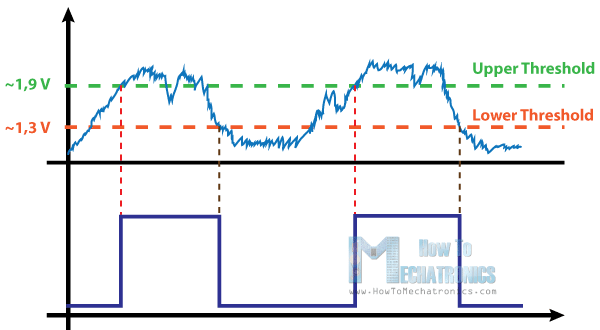
The Schmitt Trigger is a logic input type that provides hysteresis or two different threshold voltage levels for rising and falling edge. This is useful because it can avoid the errors when we have noisy input signals from which we want to get square wave signals. The Transistor Schmitt Triger circuit contains two transistors and five resistors. For better explanation I will assign values to the components, and later I will make demonstration and build this circuit on a protoboard to see how it really works.
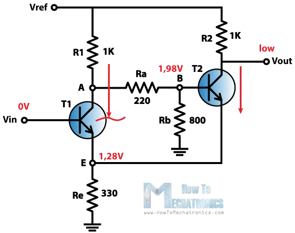
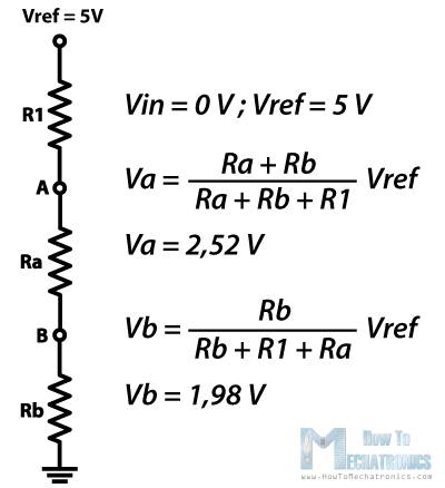
We will start like this. Let’s suppose that the Vin input is 0 V. That means that transistor T1 is cut off and not conducting. On the other hand the Transistor T2 is conducting because we have a voltage of about 1.98 V at the B node as we can consider this part of the circuit as a voltage divider and calculate the voltage using this expressions.
So because the Transistor T2 is conducting the output voltage will be low and the voltage at the emitter will be about 0.7 V lower than the voltage at the base of the transistor, or that’s about 1.28 V.
The emitter of the transistor T1 is connected with the emitter of the transistor T2 so they are at the same voltage level of 1.28 V which means that the transistor T1 will turn on when the voltage Vin at its base will be 0.7 V above this value of 1.28 V, or about 1.98 V.
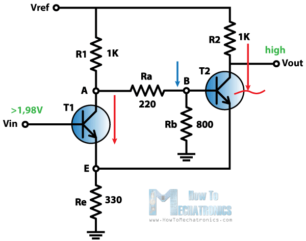
So as we increase the Vin input and we cross this value of 1.98 the transistor T1 will start conducting. This will cause the voltage at the base of the transistor T2 to drop and will cut the transistor off. As the transistor T2 is no longer conducting the output voltage will go high.
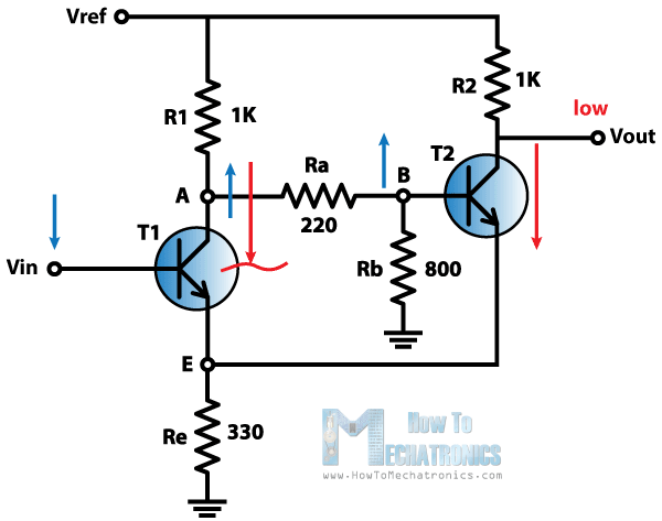
Next, the voltage Vin at the base of the transistor T1 will start declining and it will turn the transistor off when the base voltage will be 0.7 V above the voltage of its emitter. This will happen as the current in the emitter will decline to a point where the transistor will get into forward-active mode.
In this mode the collector voltage will increase, which will also increase the voltage at the base of the transistor T2. This will cause small amount of current to flow through the transistor T2 which will further drop the voltage at the emitters and will cause the transistor T1 to turn off. In our case the Vin input needs to drop to about 1.3 V to turn off the transistor T1.
That’s it. Now the cycle repeats over and over again. So we got two thresholds, the high threshold at about 1.9 V and the low threshold at about 1.3 V.
There is a demonstration of this circuit on a protoboard and it can be found at the end of the video attached above.